1. Introduction
Debris flows are significant geological disasters characterized by substantial destructiveness, leading to severe economic impacts [
1,
2]. Coinciding with global climate warming, the melting of glaciers and intense precipitation frequently initiate catastrophic debris flow events. The degradation of glaciers and permafrost makes high-altitude regions, notably the Himalayan area, particularly susceptible to debris flow disasters. Prominent examples are the three major debris flow incidents in 2007 at Tianmo Gully on the Tibetan Plateau [
3]. Numerical simulations have shown that velocities can surpass 100 m/s [
4].
In past decades, extensive research has been dedicated to disaster prevention and the mitigation of debris flows, encompassing hazard risk assessment [
5,
6,
7,
8] and the design of mitigation structures [
9,
10,
11,
12,
13,
14,
15]. To date, the study of debris flow disasters remains a focal topic [
16].
The inherently high-velocity characteristic of debris flows significantly complicates the engineering design for disaster mitigation structures. The resultant pressures, stemming from the exceedingly large velocities, frequently exceed megapascal thresholds [
17,
18], underscoring the imperative for robust design specifications. In this context, the creation of dependable energy-absorbing and containment systems emerges as a critical strategy in the defense against and alleviation of debris flow hazards.
The baffle system consists of a series of short baffles protruding from the ground surface, arranged in a certain pattern. It often serves as an auxiliary protection measure, typically placed behind the main barrier structure or buildings. As the debris flow passes through the baffle group, its velocity significantly reduces, thereby diminishing the impact forces exerted on the main barrier structure or buildings, and enhancing the protective effect [
19,
20].
Owing to their inherently simple construction and cost-effectiveness, baffle structures have garnered widespread attention in recent years. Current research endeavors primarily focus on the influence of individual baffle shapes [
21,
22], planar configuration (e.g., baffle height, spacing between baffles) [
19,
23,
24], and construction sites [
25] on the effectiveness of baffle structures as barriers. Additionally, impact models for predicting impact force and run-up height have been developed [
26,
27]. Notably, Bi et al. [
28] proposed a novel baffle design inspired by mangrove bionics, which holds promise for the development of more reliable barrier structures.
The existing research, while primarily focusing on baffles as rigid bodies [
21,
26,
29], has neglected the critical impact of baffle deformation on their protective efficiency. For instance, it is commonly suggested that increasing baffle height can significantly enhance the deceleration effect by substantially limiting the overflow behavior [
19,
30]. Nevertheless, as the height of the baffles increases or their shapes are altered, the deformation of the baffles is bound to influence the performance of the baffle ensemble, thereby limiting the optimized acceleration effect. This necessitates a deeper exploration into the deformation behavior of baffles during the interaction with the baffle groups. This investigation is crucial for providing guidelines and informing the design of baffle systems, ensuring they are more effective and adaptable to varying conditions.
In response to this challenge, a comprehensive series of physical model experiments was meticulously planned and executed. These experiments encompassed a range of parameters, including varying baffle heights, diverse baffle shapes, and combinations thereof, to carefully scrutinize the deformation characteristics of baffles under the force of debris flow impact. The collected data and insights from these experiments provide critical guidance and references for the strategic design of baffle systems, particularly in considering the potential effects of deformation.
2. Methodology
2.1. Physical Flume Model
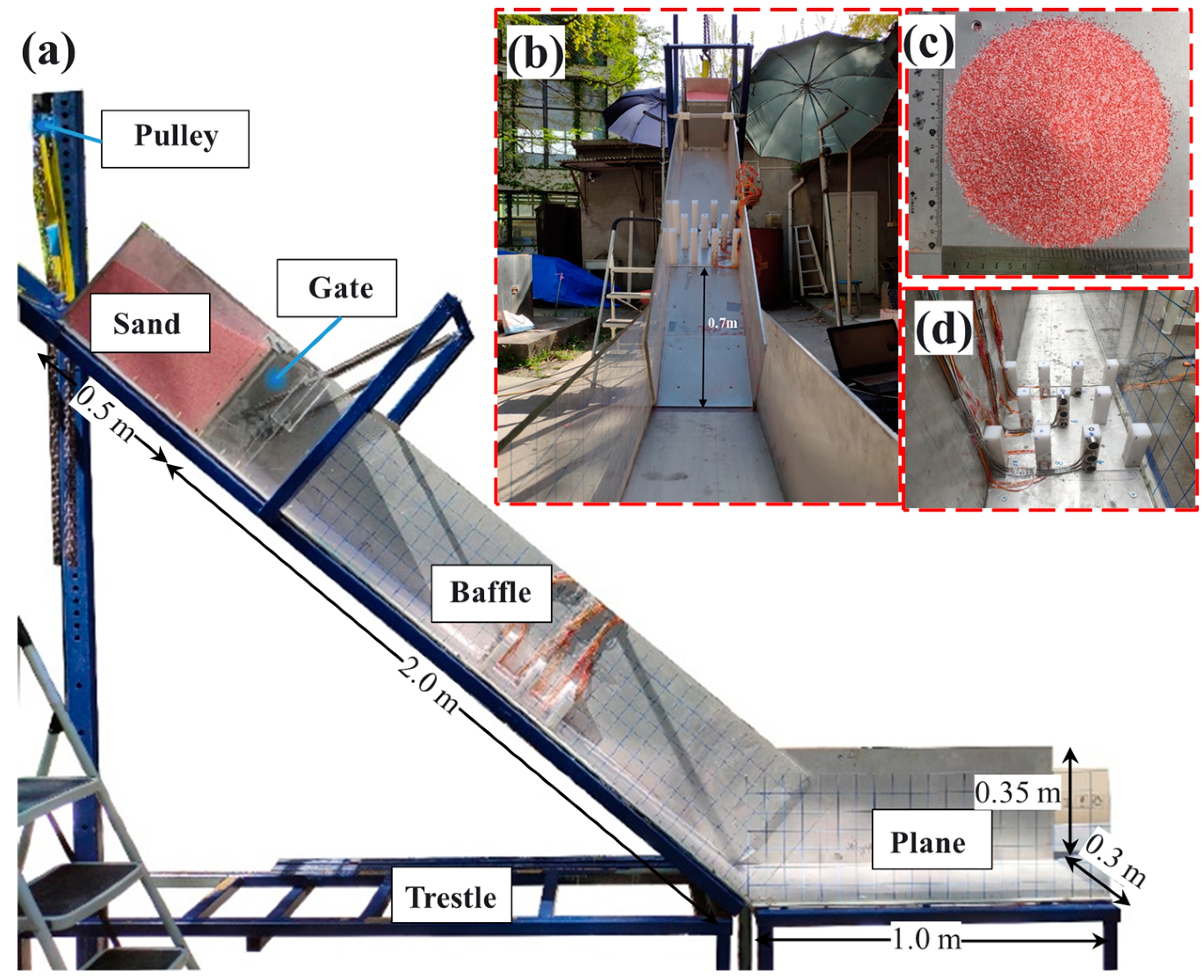
In the present investigation, physical modeling techniques were utilized to undertake an impact deformation analysis on baffle structures. The flume model, depicted in
Figure 1a, features a width of 0.3 m, a height of 0.35 m, a material container length of 0.5 m, a flow section spanning 2 m in length, and a deposition section measuring 1 m. The flume’s base and rear walls are constructed from aluminum, whereas the front walls are made of transparent plexiglass, enabling unobstructed observation and filming of the impact dynamics. Prior to the commencement of formal experimentation, a grid with 5 cm × 5 cm dimensions was meticulously marked on the plexiglass side of the flume. This grid facilitates subsequent measurements and calibrations of velocity, flow distance, and flow depth, ensuring the accuracy and reliability of the experimental outcomes.
To enable a variable incline of the flume, the flow section is pivotally connected to the deposition section. A manually operated chain hoist, positioned above the flume, allows for the dynamic adjustment of the incline angle within the range of 0° to 50°, with the experiments conducted at a 40° slope. The gate is secured to the support frame via springs and is held in place by a pin at the lower rear. Upon activation, this pin releases the gate, allowing it to swiftly rotate upwards at a 90° angle due to the force exerted by the springs. To reduce the impact force upon gate opening, a soft pad is affixed beneath the blocking bar on the support frame.
2.2. Baffle Structure
In practical engineering applications, baffle structures are predominantly constructed from concrete or reinforced concrete materials. For instance, C30 concrete, with its modulus of elasticity of 30 GPa, is a commonly employed material. In this experimental study, polypropylene was selected as the material for the baffle structures. It exhibits a modulus of elasticity of 1 GPa, a density of 950 kg/m3, and a Poisson’s ratio of 0.4. While the experiments did not adhere to strict similarity design principles to ensure stiffness equivalence, the findings obtained remain valuable. Our primary objective is to elucidate the general characteristics of baffle deformation behavior, and the results of this study are not intended for direct application to prototype-scale structures.
The arrangement of the baffles is illustrated in
Figure 1a and
Figure 2. The primary focus of this study, aligned with the experimental objectives, is to evaluate the impacts of baffle height and baffle shape. Drawing from the research conducted by Law et al. [
30], it was found that when the L/D (row spacing to baffle spacing) ratio is set to 3, the ideal baffle height, H, is determined as 1.5 h, where h represents the flow depth. Further increases in baffle height do not significantly enhance the deceleration performance of the structure. For the current experiment, the anticipated flow depth is situated within the range of 50 to 100 mm, leading to the design of baffle heights at 100 mm, 150 mm, and 200 mm. This experiment involves the creation of three rows of staggered baffles, with each square baffle (circular baffle) having a length (diameter) of 30 mm. The longitudinal blocking ratios for R1, R2, and R3 are 40%, 30%, and 40%, respectively, while the net spacing between baffles is set at 60 mm, and the net row spacing is 90 mm. The geometric parameters of the baffles are detailed in
Table 1. The experimental setup encompasses three distinct configurations using various combinations of square and circular baffles: one configuration features a group of square baffles (
Figure 2a), another presents a group of circular baffles (
Figure 2b), and the final arrangement utilizes a mix of baffles, with the first row utilizing circular baffles and the subsequent two rows employing square baffles (
Figure 2c).
In the conceptualization of the baffle structure, a 6 mm-thick aluminum base plate is utilized to anchor it to the flume’s bottom. Cuts, each 5 mm deep, are meticulously made into the base plate in alignment with the baffle group configuration. Following this, threaded holes are drilled at the base of these cuts and at the bottom of the baffle components. As illustrated in
Figure 3, securing the bolts effectively maintains a strong connection between the pile assembly and the base plate. The screws employed to stabilize the structure during the experiment are confined to a length of no more than 6 mm, thus avoiding any protrusions above the flume’s bottom surface. This precautionary measure is imperative to prevent the screws from obstructing the observation of baffle deformation. Moreover, a square indentation is machined onto the flume’s base to match the dimensions and positioning of the baffle group structure and base plate. Throughout the experiment, the baffle assembly is positioned within this indentation, and both the flume and base plate are securely connected and fastened with bolts. This method not only streamlines the replacement of components but also ensures that the top surface of the base plate is flush with the flume’s floor, thereby eliminating any potential impacts caused by the base plate’s projection during the sliding process.
2.3. Granular Material
In this experiment, quartz sand, closely mimicking the characteristics of a debris mass, was chosen as the material for the sliding body. The experimental sand was meticulously prepared by uniformly mixing red and white sand in a 1:1 ratio, enhancing the ease of observation and measurement. Considering the scale of the model and the precision of sensor measurements, the particle diameter was deliberately selected to be around 1 mm, as depicted in
Figure 1c. The calibration of the friction angle of the particles was rigorously conducted using the cylindrical uplift method proposed by Bi et al. [
24]. The interface friction angle between the quartz sand and the contact surface (encompassing the flume surface and the pile group structure surface) was meticulously determined through the tilting method outlined by Jiang and Towhata [
31]. Specific physical and mechanical parameters are comprehensively listed in
Table 2.
2.4. Instrumentation
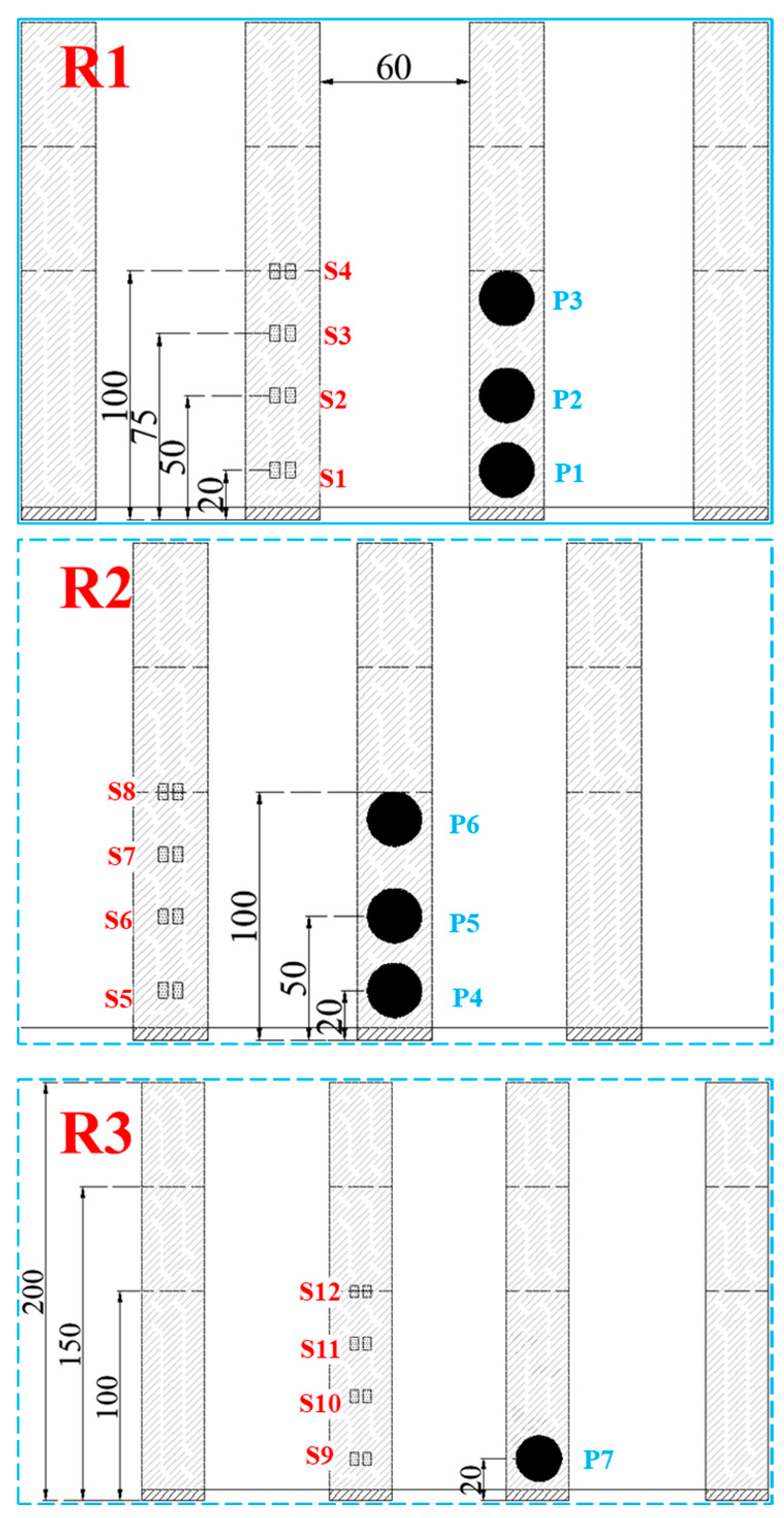
To investigate the deformation characteristics of each row of baffles under impact, the baffle structure positioned centrally within each row was chosen as the focal point for strain measurement. Strain gauges were strategically placed on the pile group structure’s surface to monitor the changes in strain and bending moment during impact. Given the substantial impact forces on the pile group structure, the anticipated deformation at the bottom is expected to be more pronounced. Therefore, placing strain gauges on the middle and lower portions of the pile group surface is both cost-effective and reliable. In this experiment, all strain gauges were interconnected using a full-bridge wiring technique. On baffles with heights of 100 mm, 150 mm, and 200 mm, 2, 3, and 4 measurement points were established, respectively. The specific sensor placement is illustrated in
Figure 4.
For the experimental setup, strain gauges with a resistance of 120 Ω, a grid length of 3 mm, and a grid width of 2 mm were employed, with a sensitivity coefficient of 2.0 ± 1%. Prior to attachment, the intended area on the baffle structure for the gauge application was carefully sanded smooth with fine-grade sandpaper and subsequently cleaned thoroughly with alcohol swabs. The strain gauges were then securely adhered to the baffle structure using cyanoacrylate adhesive. To safeguard against potential damage from sliding particles, a protective layer of sealant was evenly applied over the gauges and allowed to dry naturally. To ensure a clear visualization of the strain curve trend and mitigate the effect of environmental noise, the strain data underwent a denoising process utilizing a 6-level db4 wavelet treatment. The load cell utilized had a diameter of 22 mm and a thickness of 13 mm, capable of capturing impact pressures up to 100 kPa with an accuracy of ±0.025%. Similarly, the same data processing methodology was applied to the impact pressure results.
In addition to the aforementioned instrumentation, the experiment employed a high-speed camera with an impressive frame rate of 1000 fps and a resolution of 2048 × 1536 pixels to meticulously analyze the flow process. The camera’s filming range encompassed the entirety of the baffle group layout, extending partially upstream and downstream to capture a comprehensive view of the flow dynamics.
2.5. Testing Cases
In the present study, we systematically considered three varying baffle heights in conjunction with three distinct configuration types, totaling nine distinct scenarios. Each of these scenarios was rigorously tested three times, leading to a comprehensive collection of 27 impact tests. The most relevant scaling laws that govern the physical modeling are meticulously outlined in
Table 3.
3. Physical Modelling Results and Interpretation
3.1. Analysis of the Typical Impact Process
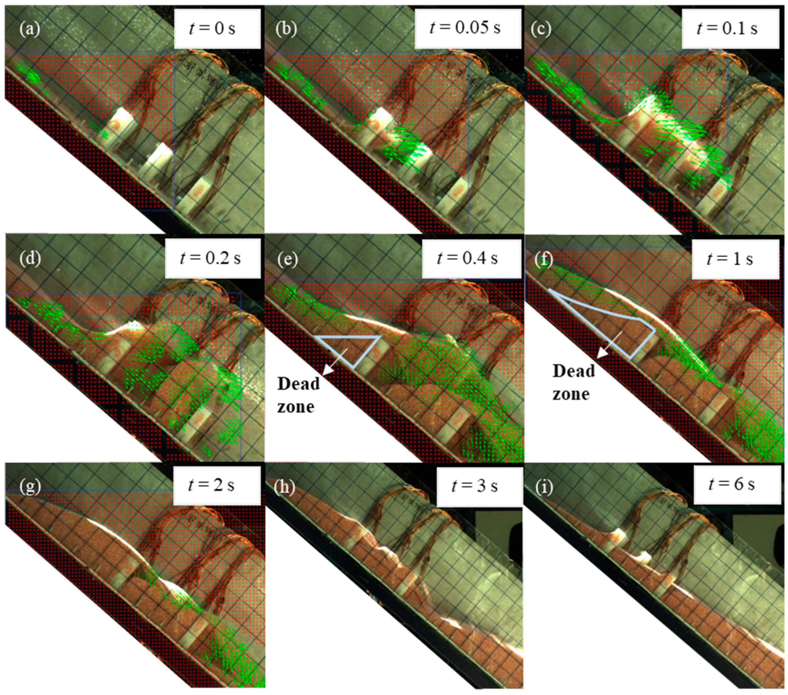
In the present paper, square baffle groups with a pile height of 100 mm were chosen for the examination of the characteristic impact process of debris flows, encompassing the following sequential phases:
- (1)
At
t = 0 s, the debris flow initiates its collision with the baffle group structure, as illustrated in
Figure 5a.
- (2)
Subsequently, part of the debris flow proceeds through the apertures between the baffles, while another segment is impeded by the baffles and commences its ascent. A small fraction of the debris bounces off the baffle structure and engages with the subsequent flowing mass, as depicted in
Figure 5b.
- (3)
The particles obstructed by the baffles experience deceleration due to the cumulative frictional collisions at the base of the flume and the baffle group structure, in addition to the particles in front of them. The lower portion of the flow gradually accumulates behind the baffles, initially creating a “dead zone”. Concurrently, the upper flow layer continues its ascent. By
t = 0.1 s, the upper flow layer has reached the peak of the first row of baffles, moving in the upstream direction, while the downstream flow has just started traversing the first two rows of baffles due to the deflection effect of the staggered baffle layout, as shown in
Figure 5c. At
t = 0.2 s, the debris flow front is just beginning to clear the piles, reaching the vicinity of the third row, as illustrated in
Figure 5d.
- (4)
Impacting on the accumulating layers in the “dead zone” at the base, which progressively increases due to the buffering friction, the flow experiences a gradual energy dissipation, transitioning from direct impact on the pile structures to stratified deposition behind the baffles. This process further expands the quiescent zone and enables the upper flow layer to traverse the surface of the quiescent zone, overtopping the baffles. By
t = 0.4 s, the overflow height of the debris flow achieves its peak, with the apex of the flow reaching 20 cm above the chute bottom and cascading directly downstream over the baffle structure. At this juncture, a considerable volume of debris material has accumulated in the baffle structure area. Post 0.4 s, as the speed of the upstream flow decreases, the overflow height diminishes. However, due to the substantial accumulation both upstream and within the baffle structure region, overflow events occur behind every row of baffles. Simultaneously, the debris flow within the structure gradually influences the downstream direction, as depicted in
Figure 5e–g.
- (5)
In the aftermath of the flow cessation at 2 s, the overflowing behavior progressively diminishes due to the absence of further upstream flow release. The debris flow commences its deceleration, as illustrated in
Figure 5h. Upon reaching
t = 6 s, the flow process ceases entirely. At this juncture, the trailing edge of the accumulated debris is positioned 29.5 cm behind the first row of piles (128 cm from the slope toe), while the front edge of the debris body has reached its farthest point, 42 cm from the slope toe.
Figure 5.
Typical impact process of debris flow on baffle structure. The dead zone is determined by the velocity field (green arrows) as the dead particles with nearly zero moving velocity.
Figure 5.
Typical impact process of debris flow on baffle structure. The dead zone is determined by the velocity field (green arrows) as the dead particles with nearly zero moving velocity.
3.2. Effect of Height on the Baffle Deformation
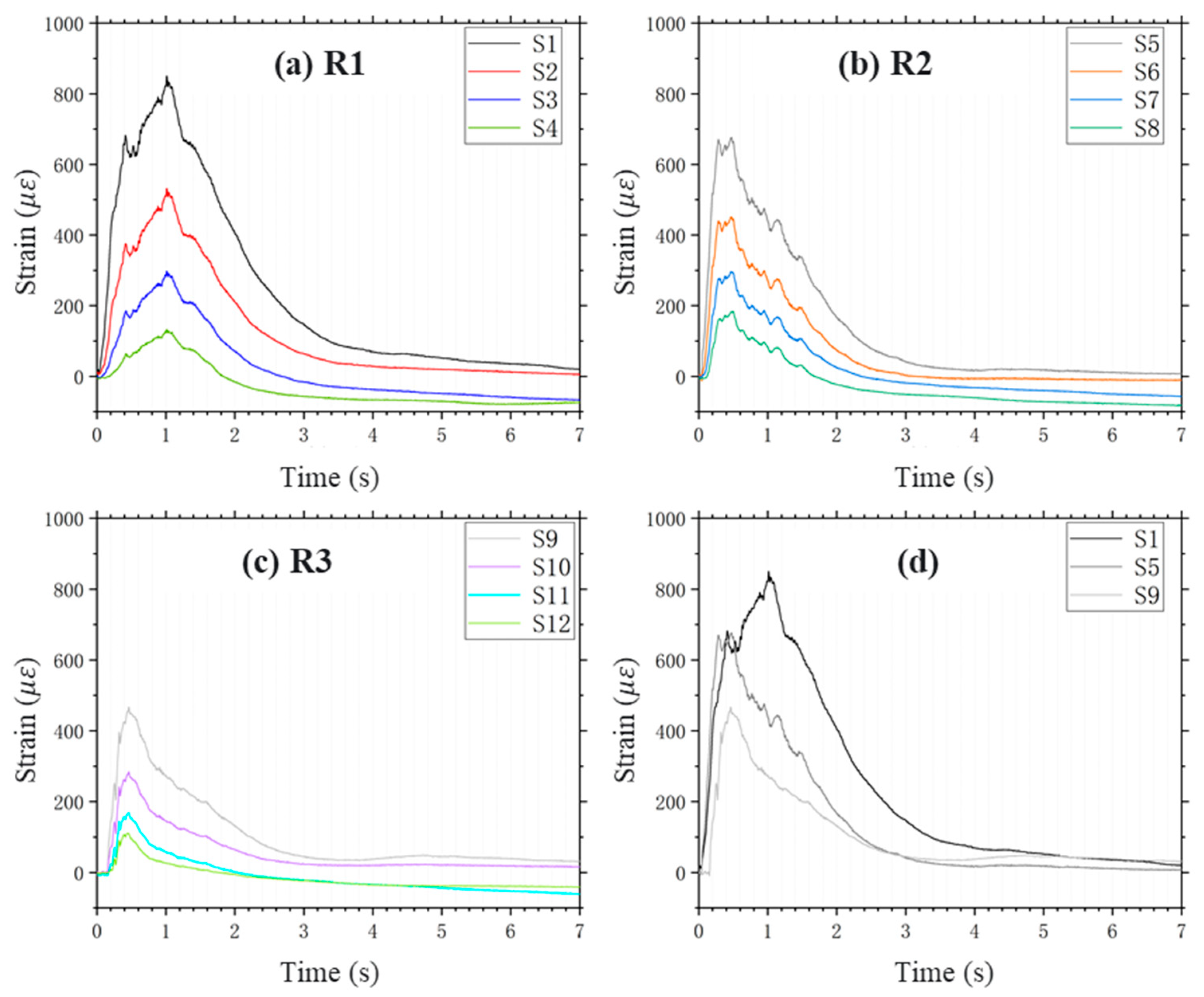
In
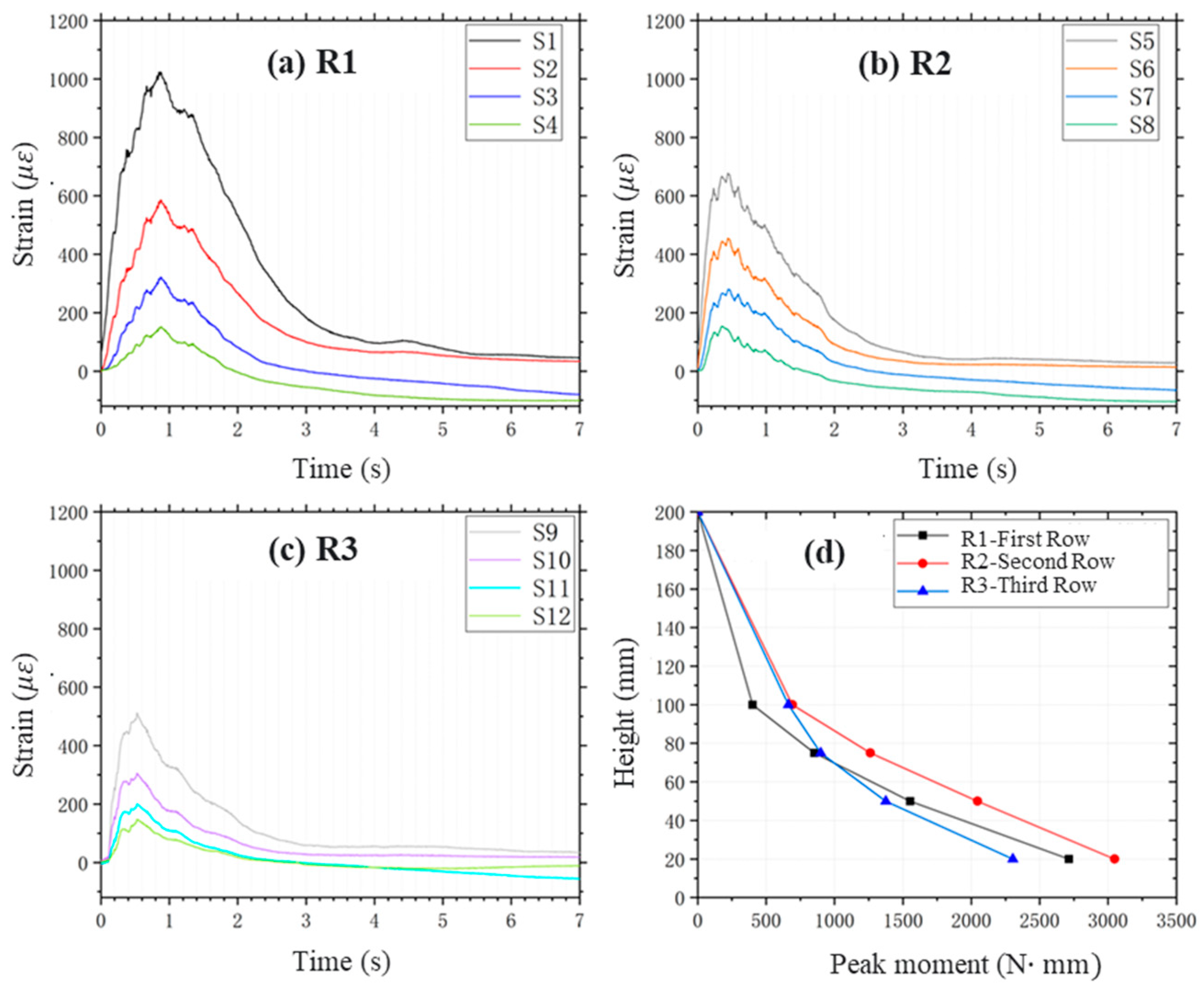
Figure 6a–c, the impact deformation behavior of a 300 mm square baffle is depicted. The time–history curves of strain for each baffle row reveal a distinct non-uniform distribution pattern. This pattern is characterized by a gradient in strain along both the flow direction and the baffle height. Notably, the strain in R1 baffles surpasses that in R2 and R3, and the strain at the lower portion of the baffle body significantly exceeds that at the mid-height.
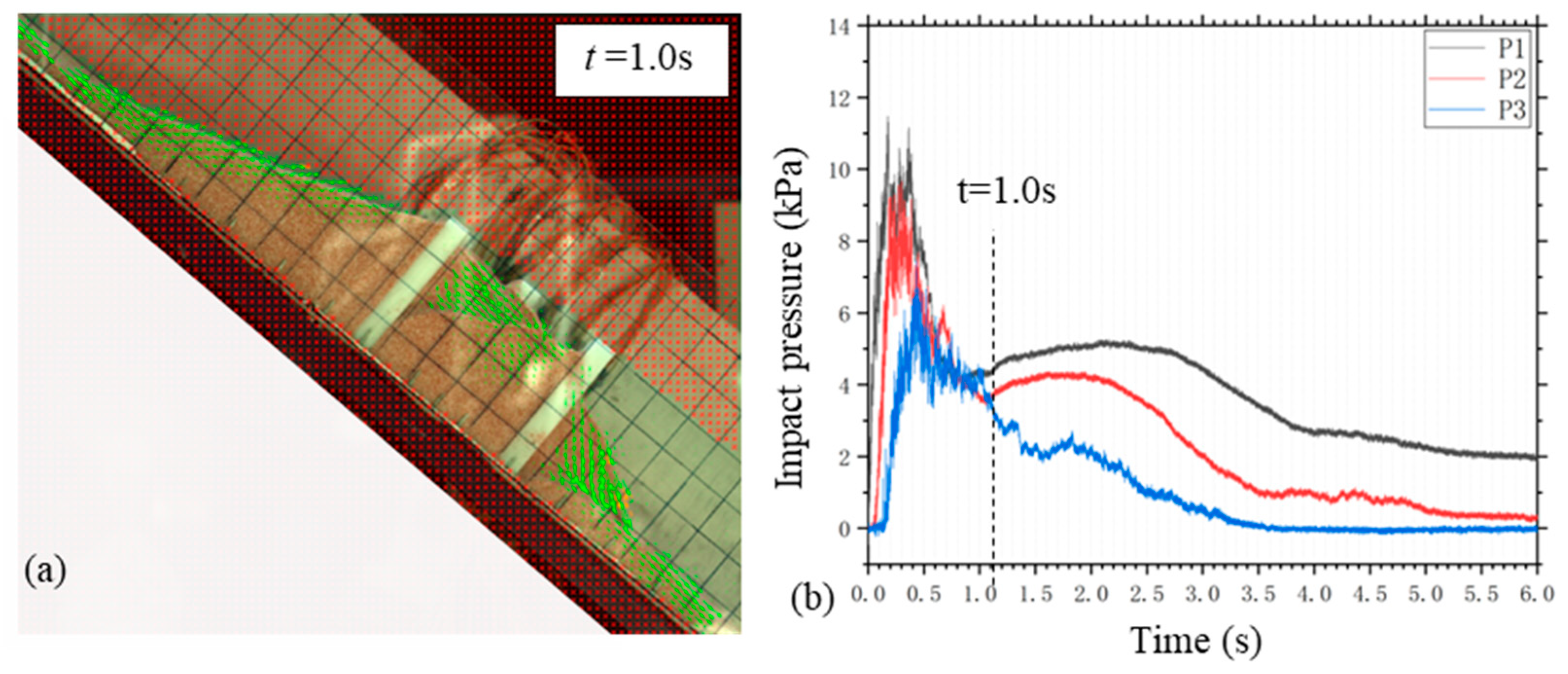
Figure 6d illustrates the synchronicity of peak strain moments at different sections of a single baffle, while peak strains at baffles of different rows occur at distinct times. For instance, R2 and R3 baffles exhibit nearly concurrent peak strain times, at 0.47 s and 0.46 s, respectively. In contrast, the peak time of strain of R1 baffles is delayed to 1.0 s due to the continual accumulation of debris flow behind the baffles, reaching maximum accumulation at this time, as shown in
Figure 7a. At this juncture, the peak impact force begins to wane, signaling the onset of the stabilization phase where impact load curves at the bottom and mid-height of the pile intersect, as shown in
Figure 7b. These observations highlight the significant influence of the quantity of accumulation behind the piles on structural deformation. This further emphasizes the importance of considering not only the energy dissipation functions of pile group structures in their design but also the effects of debris flow accumulation behind the structures on baffle deformation and damage.
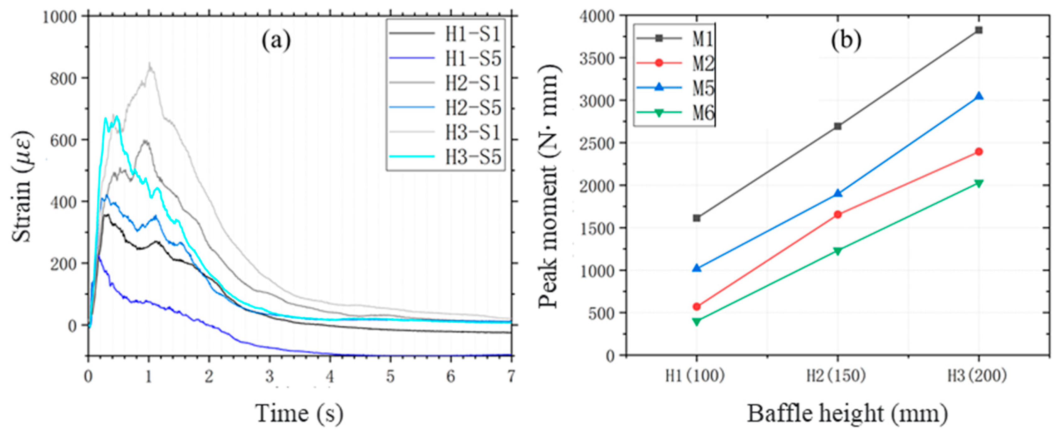
The deformation of the first two rows (R1 and R2) of the baffle structure increases with baffle height, underscoring the importance of prioritizing their resistance to deformation during the design process. To investigate the quantitative relationship between pile height and group deformation, a study was conducted using square baffle structures of varying heights, focusing on the deformation characteristics at the bottom of the first two rows of baffles.
Figure 8a presents the strain curves at the bottom of the first two rows of baffles in pile structures of varying heights, while
Figure 8b illustrates the relationship between the peak bending moments in the middle and bottom of the first two rows of baffles and the baffle height. In
Figure 4, S1 and S2 denote the strain at the bottom and lower middle of the first row of baffles, respectively, while S5 and S6 represent the strain at the bottom and lower middle of the second row of baffles, respectively.
For square baffle groups, when the baffle height is equal to or smaller than the debris flow run-up height, the strain values at various points increase proportionally with baffle height. The peak strain (bending moment) exhibits an approximately linear relationship with baffle height. At baffle heights H1, H2, and H3, the peak bending moments at the base of the baffle are 1612.9 N∙mm, 2692.8 N∙mm, and 3824.6 N∙mm, respectively. Notably, when the baffle height is doubled, the peak bending moment increases by approximately 2.37 times.
3.3. Effect of Shape and Configuration on the Baffle Deformation
The strain curves depicted in
Figure 9 for various sections within the circular baffle group illustrate the distribution of peak bending moments. It is evident that within the circular baffle structure, the most pronounced deformation is observed at the bottom of the first row of piles (
= 2548.6 N∙mm). The bending moments for the three rows of baffles converge around 75 mm in height before diverging towards the base, with the first row experiencing the steepest increase in bending moment as height decreases. This confirms that the first row of baffles is subjected to the most intense impact force.
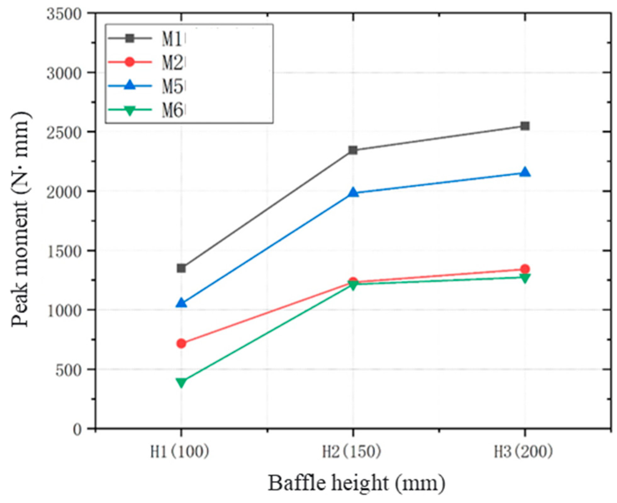
Figure 10 further elucidates the relationship between the peak bending moment and baffle height for a circular baffle group with a height of 300 mm. The peak bending moment increases as the pile height increases, with the peak bending moments at baffle heights H1, H2, and H3 being 1350.8 N·mm, 2344.4 N·mm, and 2548.6 N·mm, respectively. This contrasts with the linear relationship observed in the square baffle groups depicted in
Figure 8, where the deformation of circular baffles begins to plateau beyond pile height H2. This phenomenon is attributed to the influence of the debris flow accumulation height behind the baffle on the deformation of the baffle group structure. The maximum climb height of the debris flow behind the square baffles is notably greater than that behind the circular baffle, with the maximum heights being approximately 200 mm for square baffles and approximately 170 mm for circular baffles, as shown in
Figure 11. Consequently, baffle height H3 perfectly prevents overflow for square baffle groups, while for circular baffle groups, H3 is slightly excessive.
Figure 12 provides a visual representation of the deformation results for the hybrid baffle configurations. The replacement of the first row of square baffles with circular ones has resulted in a redistribution of the bending moments across the three rows. The impact force exerted on the first row of circular baffles by the debris flow is diminished due to the oblique collisions, in contrast to its effect on square baffles. Consequently, the location of the maximum bending moment shifts to the base of the second row of square baffles, measuring
= 3047.1 N·mm.
In comparing the bending moments at different positions within the baffle group, it is observed that the ranked sequence is R2, R2, and R3. When assessing the variation in bending moments with baffle height at various locations, the curve for the mid-to-lower section of the first row of baffles is less pronounced in comparison to the subsequent rows. Above the midpoint of the baffle group, the bending moment of the first row consistently stays lower than those of the subsequent rows.
4. Discussion
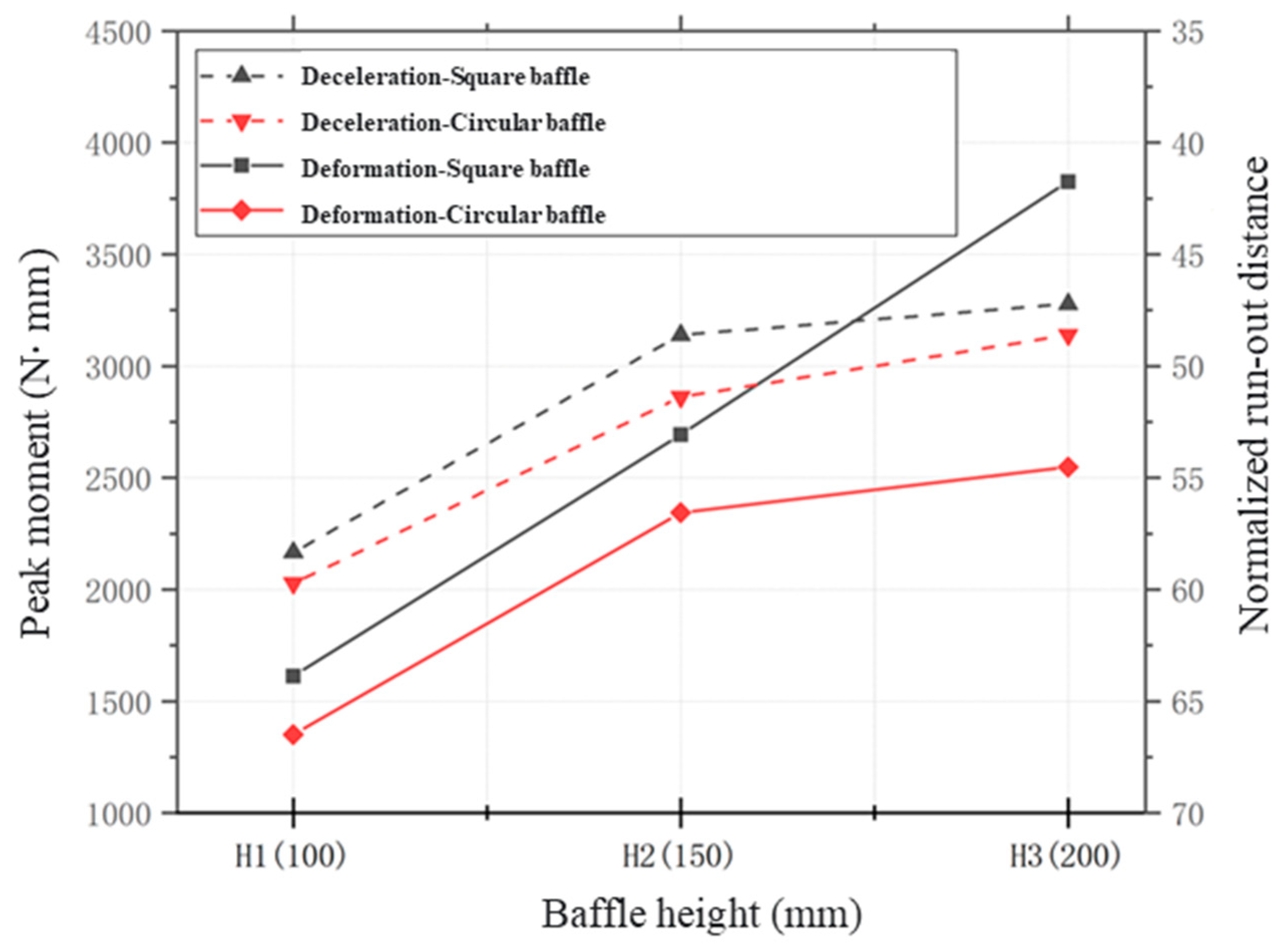
The efficacy of baffle structures is evidenced by their deceleration effect, while their protective safety is directly linked to their deformation behavior and dynamic response. Consequently, a well-designed baffle structure should be based on a comprehensive assessment that considers both of these aspects. With this in mind, this section selects the peak bending moment of the baffles and the normalized accumulation length of the debris flow front as representative indicators for evaluating the structure’s deformation and deceleration effect, respectively. The results presented in
Figure 13 illustrate the trends in the deceleration effect and structural deformation of different baffle types as the height increases.
In the case of square baffles, their deformation escalates linearly with an increase in baffle height, provided that the baffle height is less than or equal to the run-up height. This linear relationship implies that the deceleration effect tends to stabilize upon reaching height H2, signifying a gradual weakening of the deceleration effect post-H2. However, this does not undermine the continued requirement for an effective overflow control mechanism. For circular baffles, both their deformation and blocking effect grow with an increase in baffle height. The increment trend starts to diminish after reaching H2, indicating that a baffle height exceeding H2 might result in a degree of unnecessary construction waste.
A noteworthy finding is that the more pronounced the deceleration effect of the different baffle types, the higher the bending moment they can withstand. This is attributed to the retention of more material behind the baffles, which in turn increases the deformation of the baffle body. Utilizing the deceleration effect as a criterion, the optimal pile height for both square and circular piles is determined to be H2. However, when considering structural deformation as the criterion, the optimal pile heights for square and circular baffles are identified as H3 and H2, respectively.
By amalgamating the dual evaluation standards of deformation control and deceleration effect, and factoring in the impact of pile type on overflow control, we ascertain that the design of baffle structures requires a more refined approach to baffle height. This implies that when designing baffle structures, the enhanced deceleration effect resulting from an increase in baffle height should be balanced against the elevated deformation of the baffle body.
Furthermore, it is imperative to acknowledge that the current study has certain limitations. Key among these is the critical baffle height, a pivotal design parameter, which demands further detailed investigation to fully establish its implications. Our selection of polypropylene as the material of the baffle model may not fully adhere to the scaling law of structure deformation, which might limit direct upscaling of the deformation magnitude of the baffle body to a prototype scale. Although the obtained deformation magnitude may not be directly scalable, the general deformation behavior of the baffle structure should not fundamentally change. For a more rigorous analysis, the model should be built following strict similarity principles, for instance, through centrifuge modeling tests using materials that are representative of those used in the prototype [
32]. Moreover, to simplify our analysis, this work has only considered the effect of dry granular flow. The potential influence of interstitial fluid on the behavior of the granular flow, which is crucial for understanding the flow–structure interaction, is left for future research. The incorporation of solid–fluid interaction could alter the frictional behavior of the granular flow, thereby impacting the overall flow–structure interaction behavior [
33].
5. Conclusions
The present investigation delves into the dynamic deformation characteristics of baffle structures subjected to debris flow impacts. This analysis covers the influence of baffle height and baffle shape on the deformation characteristics of baffle structures, and the design of baffle structures based on the principle of deformation control. The primary insights from this study are as follows:
- (1)
The deformation of baffle structures displays a pronounced non-uniform spatial distribution pattern, with the peak bending moment being observed at the base of the first row of baffles. A temporal lag is identified when comparing the timing of the peak strain for each row of baffles and the timing of the peak impact force. This observation underscores the dominant role of the debris accumulation behind the baffles in determining the magnitude of baffle strain.
- (2)
Baffle structures with varying shapes demonstrate notable disparities in peak strain, with square baffles exhibiting higher peak bending moments in comparison to their circular counterparts. These results are attributed to the climbing behavior of debris flow along the baffle surface. Because debris flow is easier to pass the circular baffles, the run-up height and the impact force are relatively lower, resulting in diminished bending moments. The implication is clear that the strategic combination of baffles of different shapes can facilitate an optimized equilibrium between energy dissipation and deformation behavior.
- (3)
When the baffle height is less than the run-up height of the debris flow, i.e., in scenarios devoid of overflow, the peak bending moment at the base of square baffles escalates linearly with the height of the baffles. Differently, circular baffles display an initial increase in the peak bending moment followed by a plateau. However, that higher baffle means a better energy dissipation capability has already received widely agreements. Such a discrepancy between the evolution of deformation pattern and deceleration effect with the increase in baffle height highlights the critical role of the principle of deformation control in the design of baffle groups.
The insights obtained from this research provide a foundational reference for the development of baffle structures with a focus on deformation control. It underscores the imperative requirement for the meticulous design of baffle stiffness, an in-depth exploration of operational conditions that more closely mirror real-world scenarios, and an exhaustive elucidation of the evolution dynamics of baffle impact deformation under intricate conditions. This approach aims to establish a more sophisticated methodology for the design of pile group-retaining structures, thereby enhancing their efficiency and effectiveness in mitigating debris flow disasters.
Author Contributions
Conceptualization, Y.H.; Formal analysis, W.C. and B.Z.; Funding acquisition, Y.H.; Investigation, W.C. and B.Z.; Methodology, B.Z. and N.X.; Project administration, Y.H.; Supervision, B.Z., N.X. and Y.H.; Validation, B.Z. and N.X.; Visualization, W.C., B.Z. and Y.H.; Writing—original draft, W.C. and B.Z.; Writing—review and editing, W.C. and B.Z. All authors have read and agreed to the published version of the manuscript.
Funding
This work was supported by the National Natural Science Foundation of China (Grant No. 42307214), and it is also supported by the Postdoctoral Fellowship Program of CPSF under Grant Number GZB20230620 and the China Postdoctoral Science Foundation (Grant No. 2023M730354).
Data Availability Statement
All data supporting the main conclusions can be found in the submitted paper.
Acknowledgments
The authors thank the editor and the reviewers for their help to improve the quality of our manuscript.
Conflicts of Interest
The authors declare no conflicts of interest.
References
- Dowling, C.A.; Santi, P.M. Debris flows and their toll on human life: A global analysis of debris-flow fatalities from 1950 to 2011. Nat. Hazards 2014, 71, 203–227. [Google Scholar] [CrossRef]
- Petrova, E. Investigation of accidents in the infrastructure triggered by debris flows in Russia. Nat. Hazards 2022, 114, 3293–3308. [Google Scholar] [CrossRef]
- Wei, R.; Zeng, Q.; Davies, T.; Yuan, G.; Wang, K.; Xue, X.; Yin, Q. Geohazard cascade and mechanism of large debris flows in Tianmo gully, SE Tibetan Plateau and implications to hazard monitoring. Eng. Geol. 2018, 233, 172–182. [Google Scholar] [CrossRef]
- Zhang, T.; Gao, Y.; Li, B.; Yin, Y.; Liu, X.; Gao, H.; Yang, W. Characteristics of rock-ice avalanches and geohazard-chains in the Parlung Zangbo Basin, Tibet, China. Geomorphology 2023, 422, 108549. [Google Scholar] [CrossRef]
- Wu, Y.; Lan, H. Debris Flow Analyst (DA): A debris flow model considering kinematic uncertainties and using a GIS platform. Eng. Geol. 2020, 279, 105877. [Google Scholar] [CrossRef]
- Jiang, R.; Zhang, L.; Peng, D.; He, X.; He, J. The Landslide Hazard Chain in the Tapovan of the Himalayas on 7 February 2021. Geophys. Res. Lett. 2021, 48, e2021GL093723. [Google Scholar] [CrossRef]
- Luo, H.Y.; Zhang, L.M.; He, J.; Yin, K.S. Reliability-based formulation of building vulnerability to debris flow impacts. Can. Geotech. J. 2022, 59, 40–54. [Google Scholar] [CrossRef]
- Lan, H.; Tian, N.; Li, L.; Wu, Y.; Macciotta, R.; Clague, J.J. Kinematic-based landslide risk management for the Sichuan-Tibet Grid Interconnection Project (STGIP) in China. Eng. Geol. 2022, 308, 106823. [Google Scholar] [CrossRef]
- Song, D.; Chen, X.; Sadeghi, H.; Zhong, W.; Hu, H.; Liu, W. Impact Behavior of Dense Debris Flows Regulated by Pore-Pressure Feedback. J. Geophys. Res. Earth Surf. 2023, 128, e2023JF007074. [Google Scholar] [CrossRef]
- Yang, Y.; Chen, G.; Meng, X.; Chong, Y.; Shi, W.; Bian, S.; Jin, J.; Yue, D. Characteristics of the impact pressure of an outburst debris flow: Insights from experimental flume tests. Eng. Geol. 2024, 330, 107428. [Google Scholar] [CrossRef]
- Kong, Y.; Guan, M. Hydro-mechanical simulations aid demand-oriented design of slit dams for controlling debris flows, debris avalanches and rock avalanches. Eng. Geol. 2023, 326, 107314. [Google Scholar] [CrossRef]
- Ng, C.W.W.; Jia, Z.; Poudyal, S.; Bhatta, A.; Liu, H. Two-phase MPM modelling of debris flow impact against dual rigid barriers. Géotechnique 2023, 1–14, ahead of print. [Google Scholar] [CrossRef]
- Scheidl, C.; Friedl, C.; Reider, L.; Wernhart, S.; Fuchs, A.-L.; Dankwerth, A.L.; Nagl, G.; Kaitna, R.; Proske, D. Impact dynamics of granular debris flows based on a small-scale physical model. Acta Geotech. 2023, 19, 3979–3997. [Google Scholar] [CrossRef] [PubMed]
- Zheng, H.; Shi, Z.; Haas, T.; Shen, D.; Hanley, K.J.; Li, B. Characteristics of the Impact Pressure of Debris Flows. J. Geophys. Res. Earth Surf. 2022, 127, e2021JF006488. [Google Scholar] [CrossRef]
- Mao, W.; Wang, Y.; Yang, P.; Huang, Y.; Zheng, H. Dynamics of granular debris flows against slit dams based on the CFD–DEM method: Effect of grain size distribution and ambient environments. Acta Geotech. 2023, 18, 5811–5838. [Google Scholar] [CrossRef]
- Cui, P.; Ge, Y.; Li, S.; Li, Z.; Xu, X.; Zhou, G.G.D.; Chen, H.; Wang, H.; Lei, Y.; Zhou, L.; et al. Scientific challenges in disaster risk reduction for the Sichuan–Tibet Railway. Eng. Geol. 2022, 309, 106837. [Google Scholar] [CrossRef]
- Hu, K.; Wei, F.; Li, Y. Real-time measurement and preliminary analysis of debris-flow impact force at Jiangjia Ravine, China. Earth Surf. Process. Landf. 2011, 36, 1268–1278. [Google Scholar] [CrossRef]
- Thibert, E.; Baroudi, D.; Limam, A.; Berthet-Rambaud, P. Avalanche impact pressure on an instrumented structure. Cold Reg. Sci. Technol. 2008, 54, 206–215. [Google Scholar] [CrossRef]
- Ng, C.W.W.; Choi, C.E.; Song, D.; Kwan, J.H.S.; Koo, R.C.H.; Shiu, H.Y.K.; Ho, K.K.S. Physical modelling of baffles influence on landslide debris mobility. Landslides 2014, 12, 1–18. [Google Scholar] [CrossRef]
- Mast, C.M.; Arduino, P.; Miller, G.R.; Mackenzie-Helnwein, P. Avalanche and landslide simulation using the material point method: Flow dynamics and force interaction with structures. Comput. Geosci. 2014, 18, 817–830. [Google Scholar] [CrossRef]
- Kim, B.-J.; Choi, C.E.; Yune, C.-Y. Multi-scale flume investigation of the influence of cylindrical baffles on the mobility of landslide debris. Eng. Geol. 2023, 314, 107012. [Google Scholar] [CrossRef]
- Wang, D.P.; Li, Q.Z.; Bi, Y.Z.; He, S.M. Effects of new baffles system under the impact of rock avalanches. Eng. Geol. 2020, 264, 105261. [Google Scholar] [CrossRef]
- Yang, E.; Bui, H.H.; Nguyen, G.D.; Choi, C.E.; Ng, C.W.W.; De Sterck, H.; Bouazza, A. Numerical investigation of the mechanism of granular flow impact on rigid control structures. Acta Geotech. 2021, 18, 71. [Google Scholar] [CrossRef]
- Bi, Y.Z.; Du, Y.J.; He, S.M.; Sun, X.P.; Wang, D.P.; Li, X.P.; Liang, H.; Wu, Y. Numerical analysis of effect of baffle configuration on impact force exerted from rock avalanches. Landslides 2018, 15, 1029–1043. [Google Scholar] [CrossRef]
- Goodwin, G.R.; Choi, C.E.; Yune, C.Y. Towards rational use of baffle arrays on sloped and horizontal terrain for filtering boulders. Can. Geotech. J. 2021, 58, 1571–1589. [Google Scholar] [CrossRef]
- Zhang, B.; Huang, Y. Impact behaviour of dry granular flow against baffle structure: Coupled effect of Froude and particle characteristics. Geotechnique 2022. [Google Scholar] [CrossRef]
- Zhang, B.; Huang, Y. Numerical and analytical analyses of the impact of monodisperse and bidisperse granular flows on a baffle structure. Landslides 2022, 19, 2629–2651. [Google Scholar] [CrossRef]
- Bi, Y.-Z.; Wang, X.-Y.; Wang, D.-P.; Li, Z.-F.; Lovati, M.; Zhang, B. A Methodological Study on the Design Defending Baffles Based on Mangrove Bionics. Buildings 2023, 13, 310. [Google Scholar] [CrossRef]
- Yang, H.; Haque, M.E.; Song, K. Experimental study on the effects of physical conditions on the interaction between debris flow and baffles. Phys. Fluids 2021, 33, 5. [Google Scholar] [CrossRef]
- Law, R.P.H.; Choi, C.E.; Ng, C.W.W. Discrete-element investigation of influence of granular debris flow baffles on rigid barrier impact. Can. Geotech. J. 2016, 53, 179–185. [Google Scholar] [CrossRef]
- Jiang, Y.J.; Towhata, I. Experimental Study of Dry Granular Flow and Impact Behavior Against a Rigid Retaining Wall. Rock Mech. Rock Eng. 2013, 46, 713–729. [Google Scholar] [CrossRef]
- Fang, K.; Tang, H.; Li, C.; Su, X.; An, P.; Sun, S. Centrifuge modelling of landslides and landslide hazard mitigation: A review. Geosci. Front. 2022, 14, 101493. [Google Scholar] [CrossRef]
- Song, D.; Ng, C.W.W.; Choi, C.E.; Zhou, G.G.D.; Kwan, J.S.H.; Koo, R.C.H. Influence of debris flow solid fraction on rigid barrier impact. Can. Geotech. J. 2017, 54, 1421–1434. [Google Scholar] [CrossRef]
| Disclaimer/Publisher’s Note: The statements, opinions and data contained in all publications are solely those of the individual author(s) and contributor(s) and not of MDPI and/or the editor(s). MDPI and/or the editor(s) disclaim responsibility for any injury to people or property resulting from any ideas, methods, instructions or products referred to in the content. |
© 2024 by the authors. Licensee MDPI, Basel, Switzerland. This article is an open access article distributed under the terms and conditions of the Creative Commons Attribution (CC BY) license (https://creativecommons.org/licenses/by/4.0/).
