Article

Experimental Investigation of Film Thickness in Wastewater Airlift Pumps by an Image Processing Method

1
School of Mechanical and Electrical Engineering, Central South University, Changsha 410083, China
2
State Key Laboratory of Safety Technology for Metal Mines, Changsha Mining Research Institute Co., Ltd., Changsha 410010, China
3
Hunan Provincial Key Laboratory of Health Maintenance for Mechanical Equipment, Hunan University of Science and Technology, Xiangtan 411201, China
*
Author to whom correspondence should be addressed.
Water 2024, 16(14), 2010; https://doi.org/10.3390/w16142010
Submission received: 11 June 2024 / Revised: 11 July 2024 / Accepted: 12 July 2024 / Published: 15 July 2024
(This article belongs to the Special Issue Wastewater Treatment Technologies: Theory, Methods and Applications)

Abstract

:
The airlift pump is a key part of wastewater treatment and is employed as an innovative and feasible collection tool. However, as one of the key factors in the lifting capability of airlift pumps, film thickness in the gas–liquid two-phase flow operating in pumps is still an unknown topic because it is difficult to measure. This paper proposes a visualization method for measuring film thickness and investigates the film thickness when operating under gas flow with a high rate in airlift pumps using experiments. Firstly, a simulation experiment platform was built, and the images of the film structure were acquired by a high-speed camera. Then, image-processing technology and an image distortion correction were proposed to extract the gas–liquid interface for studying the thickness of the film. The experimental results demonstrated that a large film thickness ranging from 0.15 D to 0.24 D was found in airlift pumps and that its film thickness kept a constant value, even under a high gas superficial velocity, maintaining a large output liquid flow from airlift pumps. As wastewater was carried by wastewater treatment, a larger film thickness of the annular film will benefit the high lifting rate of wastewater. The works in this paper offer valuable insights for the higher performance of working airlift pumps and wastewater treatment efficiency.

1. Introduction

Nowadays, water pollution is a severe problem with the rapid development of industry and the growth of the population, especially in developing countries [1]. Water pollution is one of the causes of the drinking water crisis. Therefore, it is necessary for us to take measures to treat wastewater in the world. There are many methods and devices for wastewater treatment. Centrifugal pumps and submersible pumps, etc., are the conventional methods used in wastewater treatment [2]. However, in wastewater with high acid and alkali contents, the traditional pump life is greatly reduced; furthermore, the airlift pump with a simple structure and corrosion resistance has incomparable advantages in simple maintenance. In their study, Abed R et al. [3] found that water quality can be improved through moving wastewater using airlift pumps in the aquaculture industry, and they carried out an experiment where the airlift pump was applied into a circulation system.
The airlift pump is an innovative and feasible collection tool in wastewater treatment, as shown in Figure 1. For wastewater in the liquid phase, airlift pumps lift wastewater to the wastewater treatment container by employing compressed gas as a working medium according to a momentum exchange between the two phases. It has a very simple structure without any mechanical movement parts and is characterized by a lower cost, a higher reliability, and an easier operation, compared with traditional mechanical pumps [4,5]. Nowadays, this pump is widely used in oil exploitation, urban wastewater treatment, seabed mining, chemical liquid transportation, etc., and is considered to be one of most prospective tools in the industry [6,7].
The airlift pump is usually operated under a high gas flow condition, which shows an annular flow in its rising pipe, as reported by many researchers [8,9,10,11]. One of the key parameters the ability of lifting depends on is the film thickness because a thicker film thickness means more liquid in the same cross-section. Therefore, an excellent liquid film has a greater efficiency of lifting. However, a problem exists where its film thickness is still not completely clear to us. According to the gas flow regime maps of Kassab [12] and Stenning [13] et al., many scholars regarded this film structure as an annular flow. However, the film of an annular flow is less than 5% of its pipe diameter and can hardly maintain a high-output liquid flow. Thus, it is essential to investigate the film thickness in airlift pumps to reveal the high performance of airlift pumps under a gas flow with a high rate.
It is difficult to measure the film thickness in airlift pumps, due to the high transparency characteristics of the water and gas phases in the special film structure, with a gas core flowing along the pipe center and with a film annular flow around this gas core. Many researchers used to survey the film thickness by employing conducting probes according to the different conductivities between the two phases. For example, Hall-Taylor et al. [14] used a pair of foil electrodes to survey the thickness of the film in a vertical annular flow. Han [15] and Zhao [16] et al. also proposed wire electrodes for measuring the film thickness in a vertical pipe. Kang [17] suggested a new punch line probe and a calibration means to improve the spatial resolution for measuring the film thicknesses. Klausner et al. [18] designed a film thickness method using a probe based on the principle of capacitance measurement and successfully achieved film thickness in a horizontal tube. Even though these researchers offered many probe measurement methods for film thickness, many problems still exist in measuring the film thickness by using the probe method. One is that probes are mounted in pipes and greatly affect the gas–liquid flow structure. Another big problem is that the measurement accuracy is not high enough and is hard to verify, especially when measuring an extremely unstable film structure with some huge turbulent waves.
Visualization is an optical measurement method that does not disturb the film structure and is welcomed by researchers. Many scholars investigated the flow structure by using this method in gas–liquid flows. Asano et al. [19] visually investigated liquid distributions in adiabatic air–water two-phase flows. Wang [20,21,22] and Muntasir [23] et al. investigated the flow regimes in airlift pumps by employing high-speed photography. However, because of the film structure, the film thickness could not be observed directly from a perspective outside of the rising pipe, so the camera shooting method could not capture the film structure images directly.
To overcome the issue, this paper proposes an advanced image-processing analysis for quantifying film thickness in airlift pumps. Firstly, an annulus flow model was introduced, and the related theory of the film thickness was analyzed. Then, an experimental platform was built, and simulated wastewater treatment conditions for studying the annular flow and image acquisition and processing for a film thickness were proposed. A laser sheet was employed to capture the film structure by employing high-speed photography. At last, the characteristic of the film thickness in airlift pumps was studied, and the film thickness was investigated at different gas superficial velocities and submergence ratios, based on image-processing results.

2. Theoretical Analysis of a Film Thickness

At present, the film thickness in a gas–liquid flow is still not fully known to us. Thus, in order to make use of wastewater lifting technology and obtain a higher efficiency of lifting wastewater, it is a necessary for us to investigate the film thickness under a gas–liquid phase flow condition. As shown in Figure 2, when the pump operates at a high gas intake, a continuous gas core structure is easily formed at the center of the lifting pipe under a high air intake, and the liquid film around this continuous gas core is balanced by an interface shear force and flows up along the pipe wall.
For a stable annular flow in Figure 2, the mechanical equilibriums for the film phase and the gas phase can be expressed as:
A L d p d z τ L S L + τ i S i ρ L A L g = 0
A G d p d z τ i S i ρ G A G g = 0
where τi is the gas–liquid interface shear force, τL is the friction between the liquid film and the lifting pipe wall, p is the pressure of the mixed fluid, z is the vertical flow distance, ρ is the density, SL is the contact area between the liquid film and the lifting pipe wall, Si is the gas–liquid interface area, AL is the cross-sectional area of the liquid film, and AG is the cross-sectional area of the gas core; subscripts G and L denote the gas phase and the liquid phase, respectively.
According to the film thickness δ and the pipe diameter D, SL, Si, AL, and AG can be calculated as π D , π ( D 2 δ ) , π ( D δ δ 2 ) , and π ( D / 2 δ ) 2 , respectively. By combining Equations (1) and (2), the pressure drop term in Equations (1) and (2) can be removed, and a new formula can be rewritten as:
τ i S i ( 1 A G + 1 A L ) ( ρ L ρ G ) g τ L S L A L = 0
The friction τL can be expressed as:
τ L = 1 2 f L ρ L u L 2
where fL is the friction factor between the liquid film and the lifting pipe wall, and uL is the actual velocity.
The friction τL can also be estimated in a formula similar to that in Equation (4), as the gas phase velocity is much greater than that of the liquid phase in airlift pumps. Thus, the friction between the gas–liquid interface can be estimated by:
τ i = 1 2 f G ρ G u G 2

3. Experiment

3.1. Experimental Device

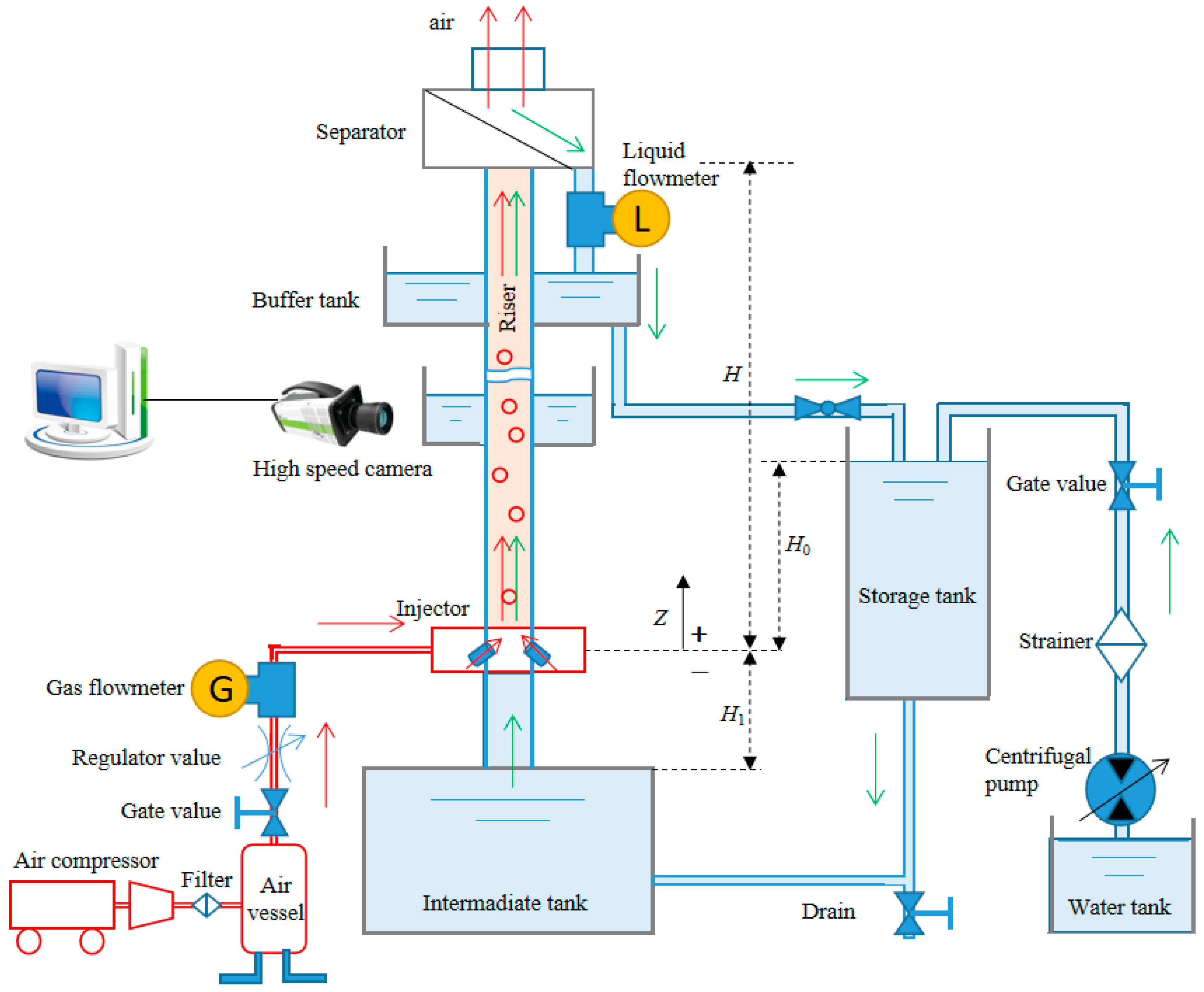
Based on the working principle in Figure 1, a simulation experiment platform was built. As shown in Figure 3, the experimental airlift device consisted of a submerged pipe, a rising pipe, an air injector, an air compressor, and a water intermittent tank. Gas supplied by an air compressor with a maximum discharge of 60 m3/h flowed into the air injector, and the liquid in the intermittent tank was sucked into the bottom of a rising pipe, flowing together in the lifting pipe to form an annular flow structure, which flowed along the pipe until it reached a separator, where gas was discharged into the atmosphere while liquid was discharged into a storage tank for cyclic utilization. The submerged depth H0 is the vertical distance from the air injector to the liquid level of the storage tank. H1 is the suction pipe length where the water flows. H is the rising pipe length where the gas–liquid mixture flows. A submergence ratio is a ratio of the submerged depth to the rising pipe length (γ = H0/H). In this experiment, the rising pipe was made of transparent organic glass, with a 2500 mm length and a 40 mm inside diameter. The ratio γ can be regulated by controlling the water volume in the storage tank through a water pump. A gas flowmeter with an accuracy of ±1% and a liquid flowmeter with an accuracy of ±0.5% were installed near the air injector and separator, respectively, and they were employed to measure the gas flow rate and the liquid flow rate, respectively.

3.2. High-Speed Photography

As we know, one of the accurate methods for measuring the film thickness is to obtain its images. However, the film thickness could not be observed directly from a perspective outside of the rising pipe because its gas–liquid interface was blocked by the annular film. Thus, high-speed photography with the help of a laser sheet was employed in this experiment. A sheet was illuminated by a laser, and the gas–liquid flow in this laser sheet was captured by the high-speed camera. Image-processing technology was also employed to identify the film thickness according to a difference in gray levels between the gas and liquid phases.
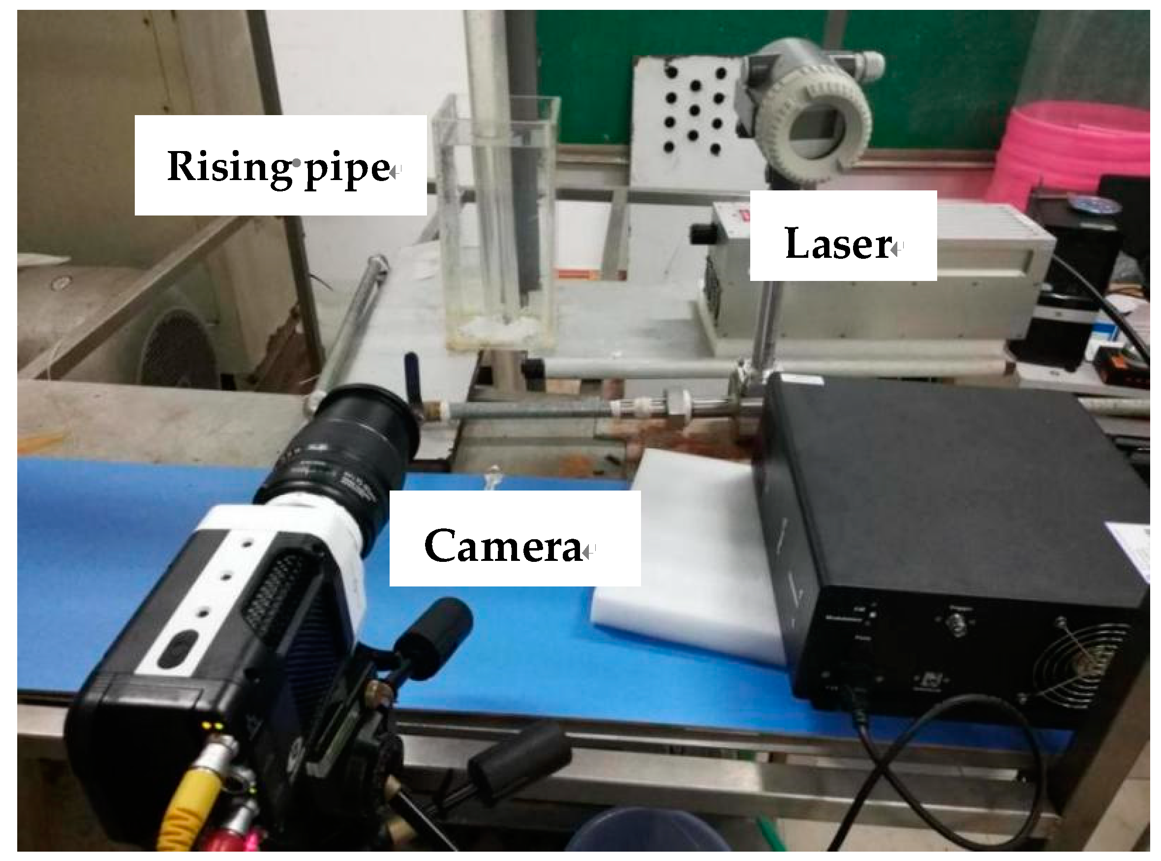
The high-speed image technology is shown in Figure 4. A laser source was used to light a sheet through the pipe center with a light wavelength of 457 nm. A high-speed camera was mounted perpendicularly to this sheet with a shooting frequency of 1000 Hz. To reduce the image distortion caused by an optical refraction in the circular rising pipe, a rectangular water tank was also mounted in the test section. The optical plane passing through the lifting pipe axis line was provided by a continuous laser source in a dark room, and the high-speed camera was facing the plane. Only one plane was illuminated by the laser in the dark scene, and the high-speed camera could acquire the information of the annular flow on the light plane accurately.
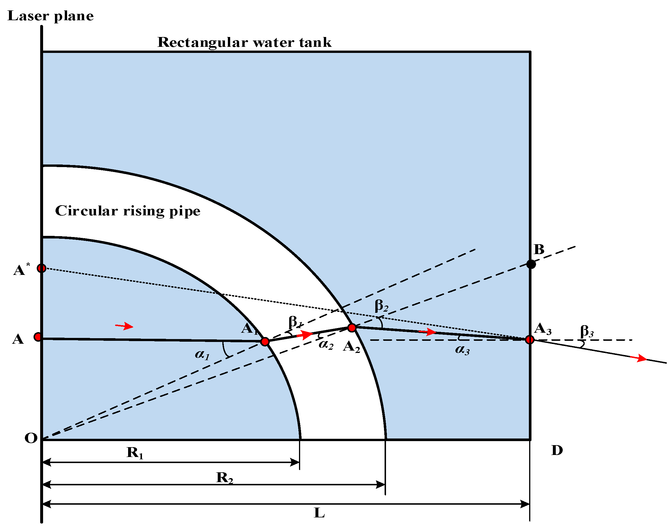
Even though this rectangular water tank could reduce the image distortion, there still existed an error between the captured image and the true image. A beam path diagram for a random point (A) in the sheet is shown in Figure 5. For the parallel light from this original point, it passed through three points (A1, A2, and A3), which were not in the same line due to an optical refraction. Thus, the point we observed (A*) was a virtual point that had an excursion away from the true point.
The beam path was refracted three times: at the pipe inner wall, at the pipe outer wall, and at the rectangular wall. It was supposed that the incidence angles in these three places were α1, α2, and α3, respectively. It was supposed that the departure angles for leaving these three places were β1, β2, and β3, respectively. According to the refraction theorem, the incidence angles and the departure angles obeyed the following rules:
sin α 1 sin β 1 = n 2 n 1 , sin α 2 sin β 2 = n 1 n 2 , sin α 3 sin β 3 = n 3 n 1
where n1 is the refractive index of water in the rising pipe, n2 is the refractive index of the pipe transparent organic glass, and n3 is the refractive index of the atmosphere outside the rectangular tank.
A beam path first reached point A1 and then refracted to point A2. In the triangle △A1A2O, the location relationship between these two points obeyed the formula:
O A 1 sin A 1 A 2 O = O A 2 sin A 2 A 1 O
where OA1 is the inside diameter of the rising pipe (R1), and OA2 is the outside diameter of the rising pipe (R2).
According to the geometrical relationship, sin A 1 A 2 O = sin α 2 , and sin A 2 A 1 O = sin β 1 . Combining Equations (6) and (7), expressions for the angles of α1, α2, β1, and β2 were derived as sin 1 ( O A / R 1 ) , sin 1 n 1 R 1 sin α 1 / ( n 2 R 2 ) , sin 1 n 1 sin α 1 / n 2 , and sin 1 R 1 sin α 1 / R 2 , respectively. Once the angles of α1, α2, β1, and β2 were determined, the angle α3 was also derived from the geometry in Figure 5, as follows:
α 3 = π 2 A 2 A 3 B = i = 1 2 ( β i α i )
Thus, the angle β3 was calculated, according to Equation (6), as follows:
β 3 = sin 1 ( n 1 sin α 3 n 3 )
The distance from the pipe center (point O) to the virtual point (point A*) was calculated as follows:
O A * = A 3 D + L tan β 3
where L is half the length of the rectangular box.
The distance A3D in Equation (10) was calculated, according to the geometry in Figure 5, as follows:
A 3 D = L tan ( α 1 + α 2 β 1 ) L sin β 2 R 2 sin β 2 cos ( α 1 + α 2 β 1 ) sin ( π 2 + i = 1 2 ( α i β i ) ) cos ( α 1 + α 2 β 1 )
From α1, α2, β1, β2, and Equations (9)–(11), the relationship between the true point A and the virtual point A* was very complex, and it was not easy to directly solve its explicit equation between the locations of these two points. Thus, a polynomial function was employed to describe the distortion factor between these two points, as shown below:
O A = a 0 + a 1 O A * + a 2 ( O A * ) 2 + + a n ( O A * ) n
where a, a1, and an were fitting parameters. To obtain these fitting parameters, a series of OA values were given, and their corresponding virtual points (OA*) were calculated according to α1, α2, β1, β2, and Equations (8)–(11). Then, the fitting parameters were obtained according to a polynomial fitting method. The fitting map is shown in Figure 6, and its fitting result was:
O A = 0.2936 + 0.631 O A * + 1.239 × 10 2 ( O A * ) 2 3.983 × 10 4 ( O A * ) 3

3.3. Image Processing for a Film Thickness

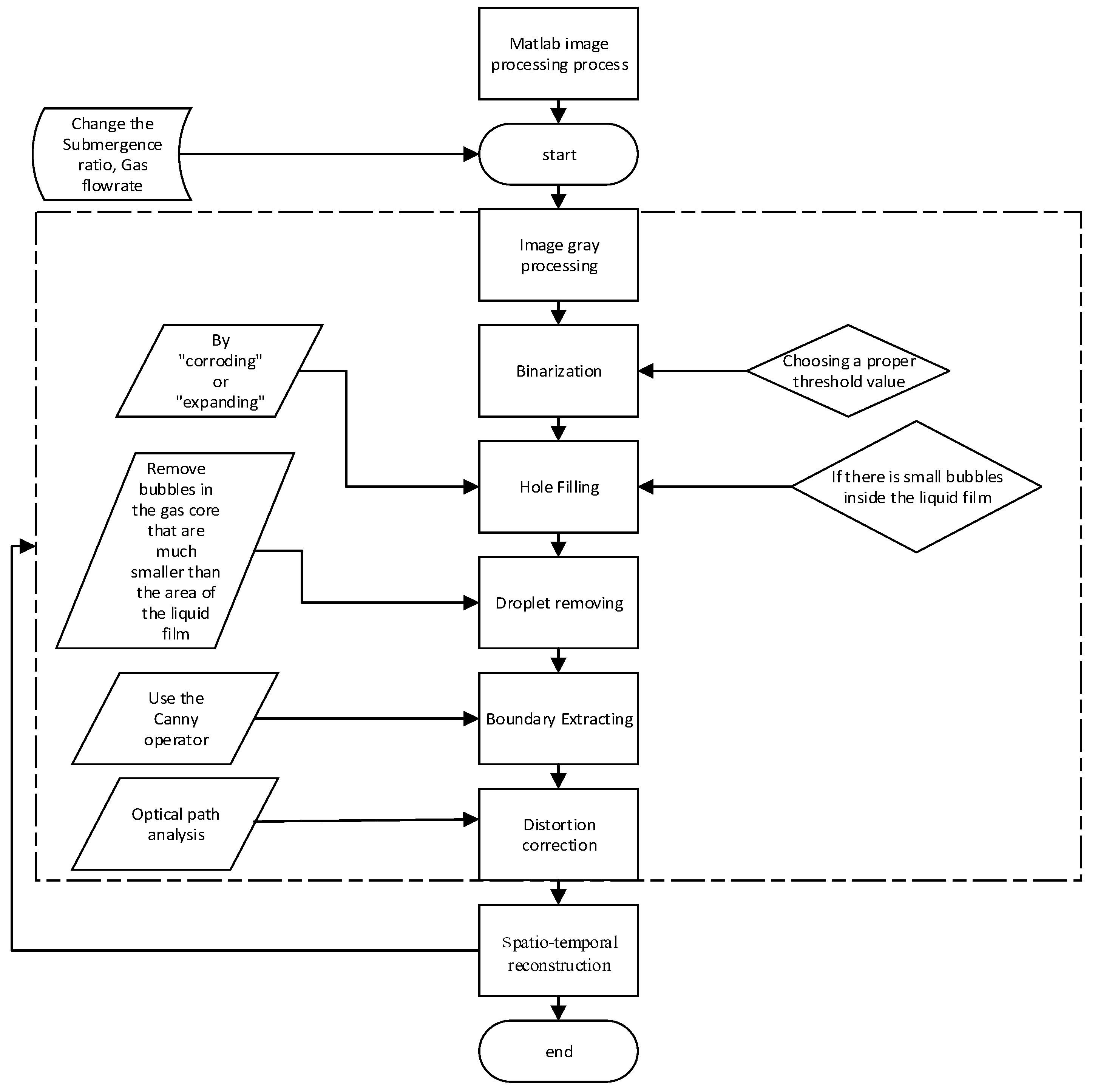
The film thickness could be estimated from the coordinate of the gas–liquid interface. Thus, image processing was employed to extract this gas–liquid interface. A flow chart for the image processing is shown in Figure 7. For the original image, there were mainly 6 steps to obtain its film thickness.
(1)
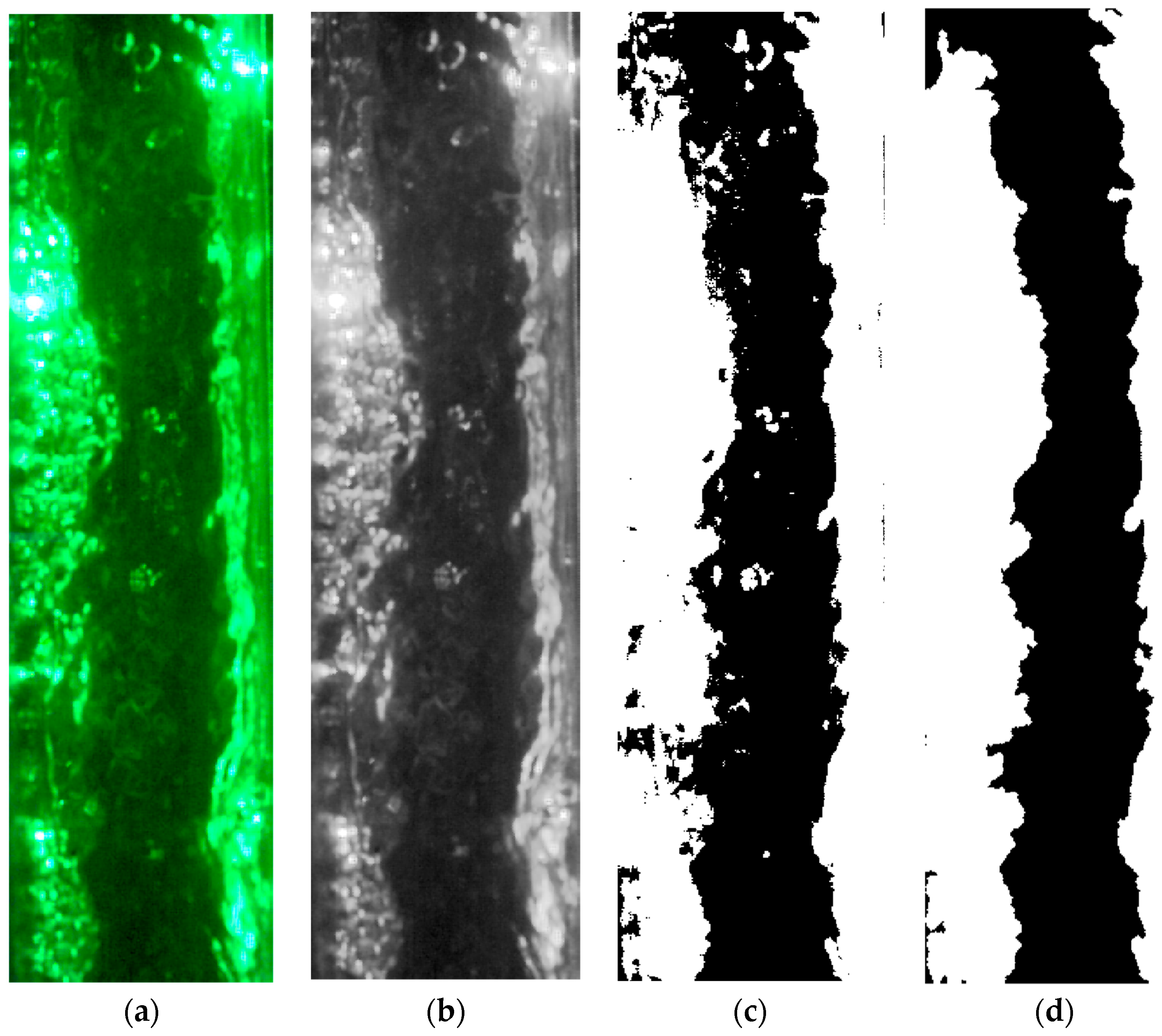
Grayscale processing. The original image was transformed into a grayscale image. The gray levels of the gas and liquid phase were obviously different, as shown in Figure 8b. The gray level of the gas core was much smaller than that of the water phase because the gas core is colorless in airlift pumps.
(2)
Image binarization processing. The point of the colorless gas core in the gray image was treated as a background, while the point of the liquid phase was treated as a target. An image threshold was employed to distinguish these two different phases and then to transform the grayscale image into a binary image.
(3)
Image hole filling. There existed some small holes in the film structure because some small bubbles were entrained in this film structure. Thus, these small holes in the liquid film were effectively filled using a hole-filling method, as shown in Figure 8c.
(4)
Droplets removing. Some droplets were suspended in the gas core in the rising pipe, which may affect the estimation of the film thickness. These droplets usually had a much smaller size than that of the liquid film. Thus, the areas of the droplets were removed by setting the gray level of small areas to 0, as shown in Figure 8d.
(5)
Boundary extraction. The gas–liquid interfaces can be seen in Figure 9a. To achieve the coordinate values of the left and right interfaces, the binary image without liquid droplets was divided into two figures from the pipe central axis. An edge-detection algorithm was employed to extract the two gas–liquid interfaces.
(6)
Image distortion correction. According to the correction function in Equation (13), the real coordinate of the gas–liquid interface can be calculated, as shown in Figure 9b.

3.4. Validation of the Image-Processing Method

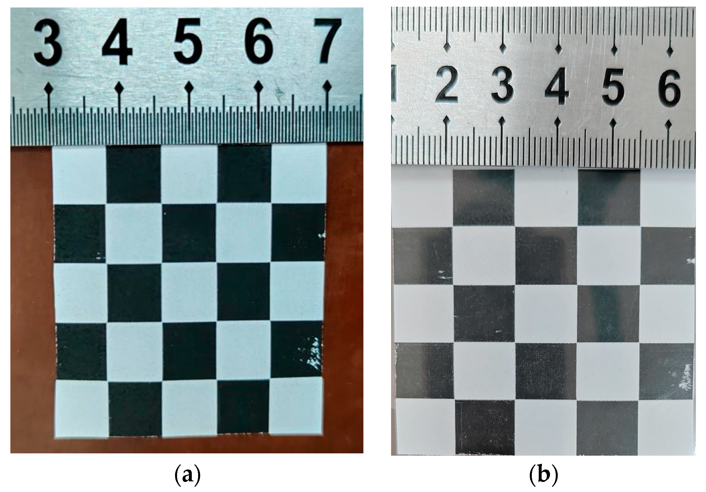
The accuracy of the image-processing method was validated by fixing a uniform square grid (8 mm × 8 mm) checkered with black and white on the central plane of the organic glass pipe with an inside diameter of 40 mm; the object images in air medium were measured, as shown in Figure 10a, and then the same object images placed on the central plane of the organic glass pipe filled with water medium were measured, as shown in Figure 10b. Firstly, the undistorted grid was measured using a ruler and recorded by a camera before being immersed in the water pipe. The distorted grid in water medium was also measured and recorded in the vertical plane. Then, we obtained the true image of the interface from the distorted grid in the water medium using the image-processing method. The grid distortion was compared by examining the variation of the dimension in each grid using a ruler.
A validation of the image-processing method can be performed using the step shown above. The mean size of the distorted grid in water medium in each row that was measured by a ruler was 11 mm, as shown in Figure 10b. The corrected grid size was calculated as 8.204 mm using Equation (13), and the true grid size was 8 mm. The max relative error of the uncorrected grid size was over 30%, but the relative error of the corrected grid size was only 2.5%; therefore, the method greatly reduced the distortion. The verification results showed that the corrected size was in good agreement with the true grid.

4. Results and Discussions

It has been proven that the output liquid flow first increased with an increase in the gas flow rate and then was maintained at a constant with a further increase in the gas flow rate. A curve of the superficial velocity between the liquid and the gas was shown in Figure 11, which was consistent with the findings of previous researchers [24,25]. The stable stage at JG ≥ 3.1 m/s in Figure 11 was suggested to be an annular flow, based on the classical flow regime map, as reported by Hu [24], Hanafizadeh [25], and Cho [26] et al, but there was doubt as to how the annular flow kept a high flow rate of the output liquid because there was only a thin liquid annular flow along the pipe in the annular flow.
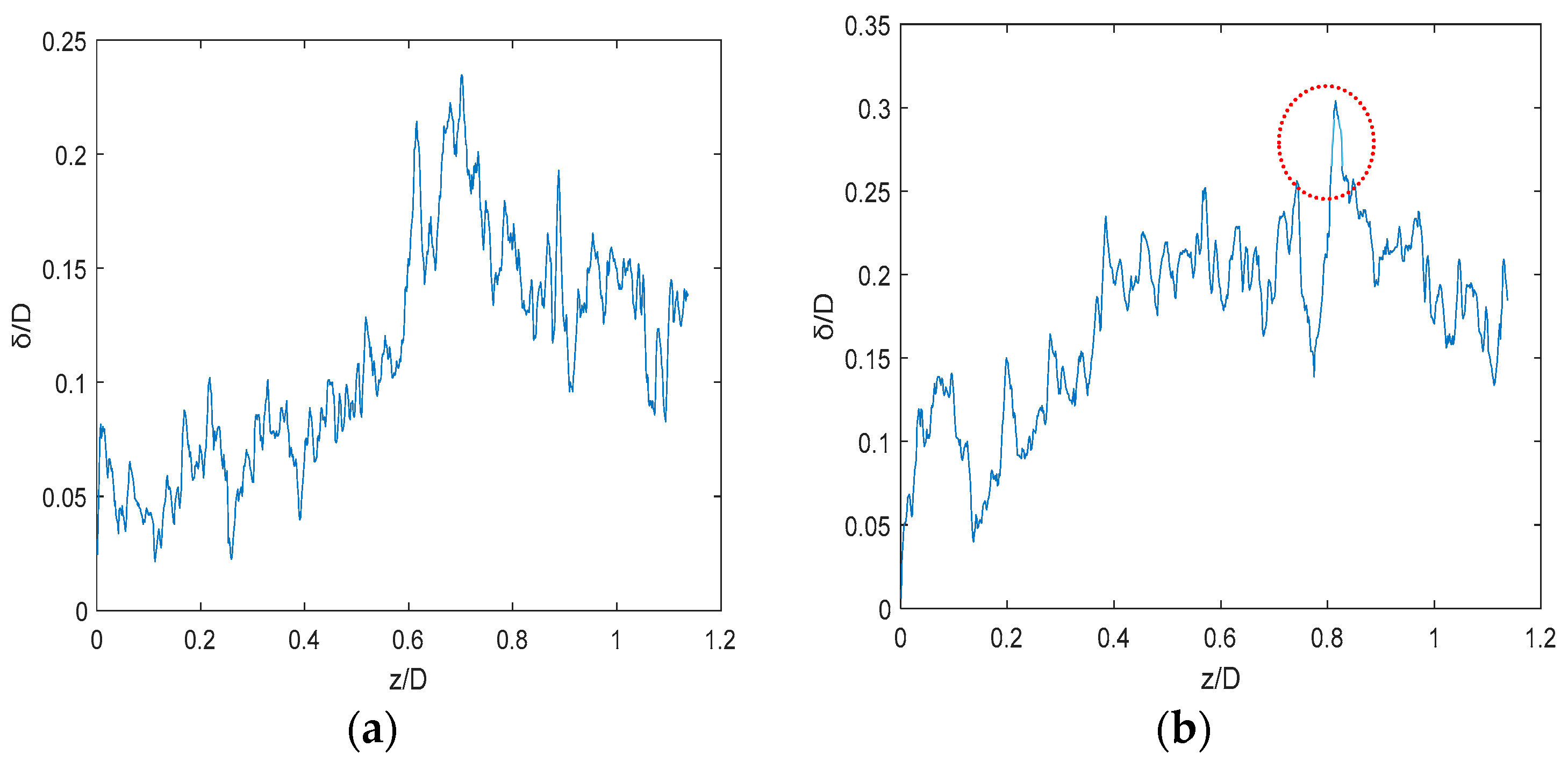
According to the interface images, we redrew the dimensionless film thickness in its flow direction. Figure 12 shows the changes in the dimensionless film thickness along the pipe at t = 0 s and t = 0.28 s. It can be seen that the average thickness was 0.15 D, which was much larger than that in the stable annular flow. The film thickness in the stable annular flow was less than 0.06 D, as reported by Wallis [27], Henstock [28], and Kabir [29] et al. This further proved that the flow regime in airlift pumps was not the classical annular flow.
Another phenomenon can be seen in Figure 12, where the film thickness was not uniformly distributed. An extreme peak can be observed at z/D = 0.8 in Figure 12. Compared with the stable film structure in the annular flow, this annular flow was also unstable and easily formed a liquid bridge once the peak value exceeded 0.24 D.
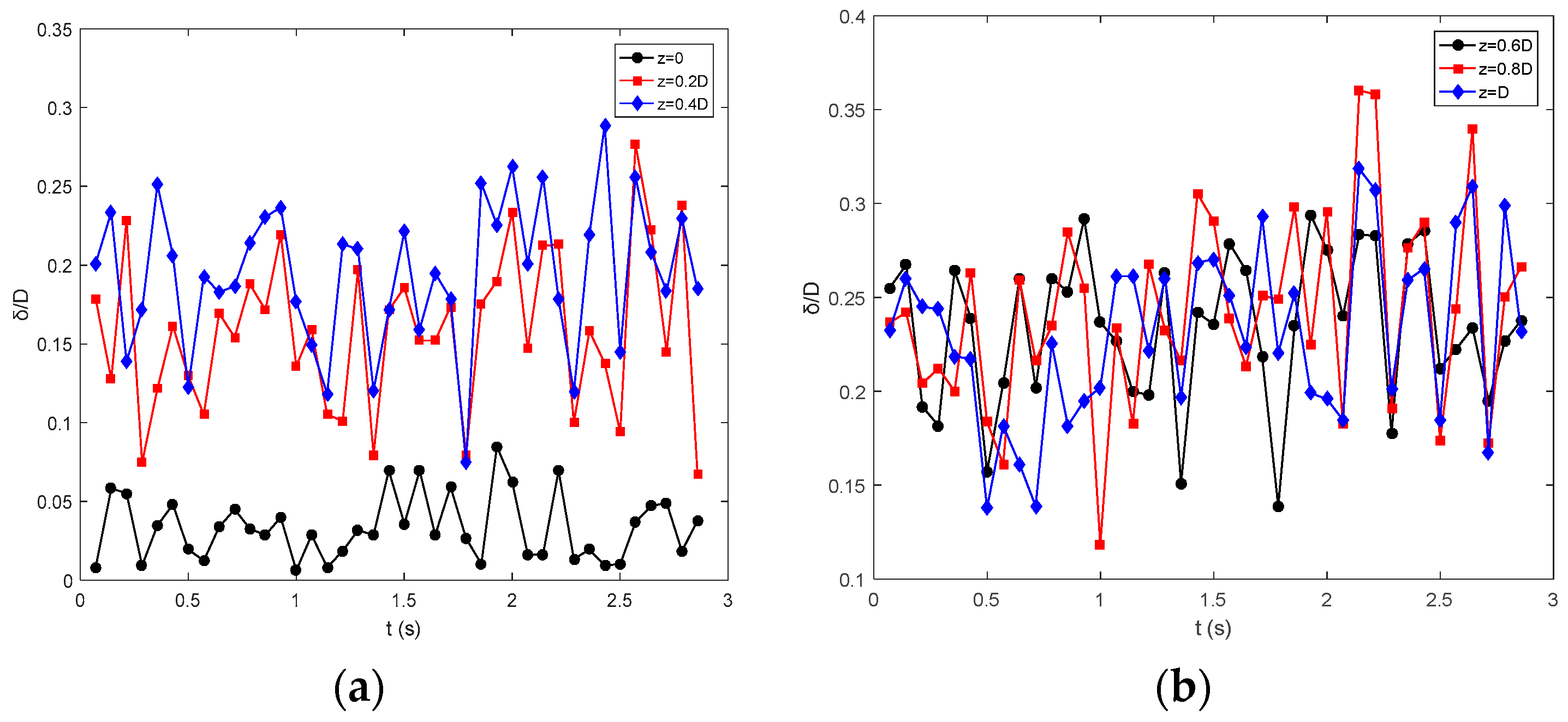
The time variants of this film structure at different pipe axial positions are shown in Figure 13. Note that the gas–liquid interface fluctuated drastically, even at the same observation point. Combining Figure 12 and Figure 13, it can be seen that the film thickness not only fluctuated with the space, it also fluctuated with the time. Thus, it was necessary to reconstruct the film structure in the time–space dimension to investigate the characteristics of film thickness.
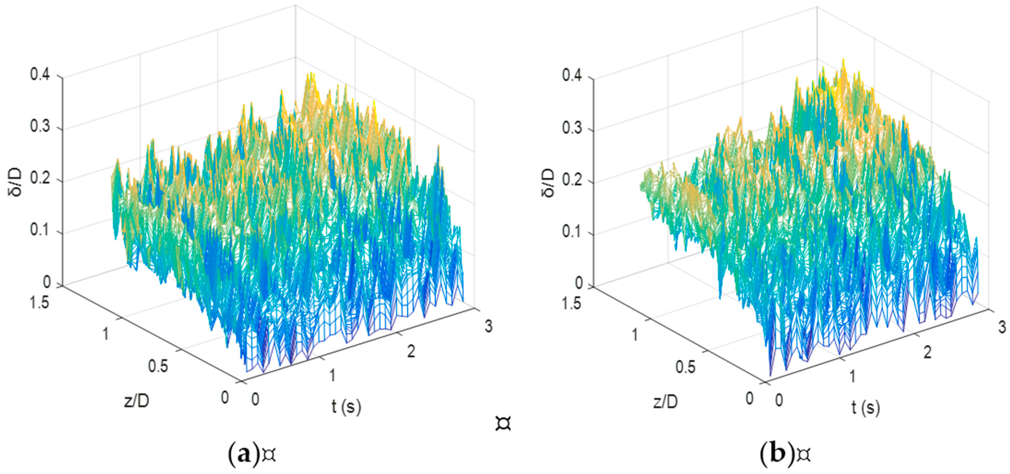
The spatial–temporal reconstruction of the film thickness is shown in Figure 14. As can be seen, the film thickness was characterized by an obvious fluctuation, which greatly improved the momentum exchange between the two phases. That was one of the reasons why the output liquid could maintain a large flow rate under an annular flow structure.
The average thickness of film was calculated from the spatial–temporal reconstruction, as shown in Figure 14. Figure 15 shows the curve of the mean film thickness with different gas superficial velocities. Note that the mean film thickness was in the range of 0.15 D–0.24 D, which was much larger than that in a stable annular flow. For this thick film, its movement was very unstable. Wang et al. [21,22] found that the film had an up-and-down movement in the gas flow with a high rate. Note that the mean film thickness decreased to a stable one with an increasing gas superficial velocity at γ = 0.3. In general, the film thickness was inversely related to the gas superficial velocity. However, its thickness maintained a constant value at a high gas superficial velocity (JG > 10.5 m/s). This was caused by the turbulent waves in its gas–liquid interface. For the uncontrolled water flow in airlift pumps, its wave fluctuated more dramatically when the gas superficial velocity increased. This wave greatly promoted the interface friction and kept a constant film thickness, which finally resulted in a high liquid discharge in airlift pumps.
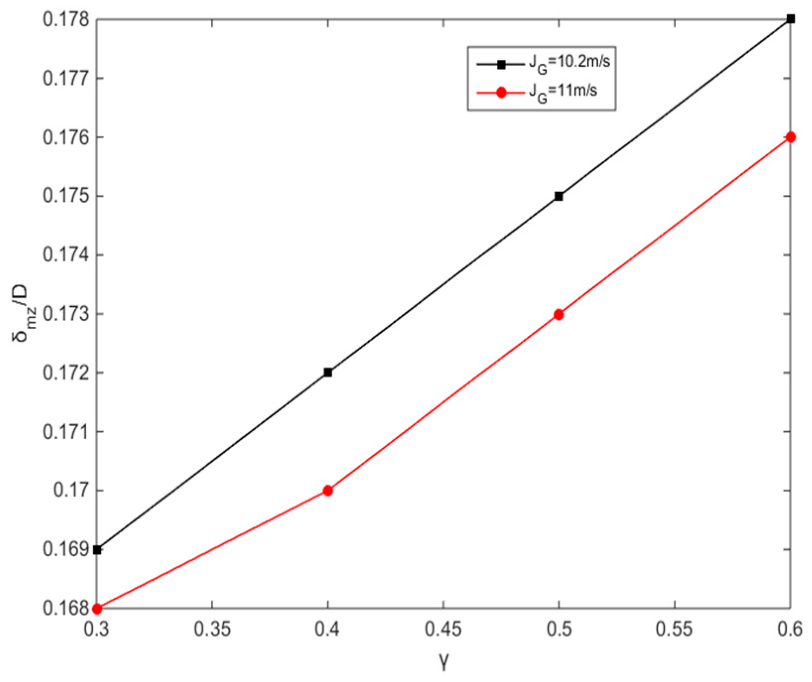
Also, the submergence ratio affected the mean film thickness, as shown in Figure 16. Note that the film thickness increased with an increase in the submergence ratio. Usually, a large submergence ratio can increase the pressure drop and bring a high liquid discharge into the airlift pump. Thus, the film became thicker when the submergence ratio was increased.

5. Conclusions

In this paper, the characteristics of film thickness in airlift pumps operating at high gas flow rates were investigated using experiments. A visualization method for measuring the film thickness in airlift pumps was developed, and the images of the film structure were captured by employing a high-speed camera. Image-processing technology and an image distortion correction were proposed to extract the gas–liquid interface to investigate the film thickness. The thickness of the film in the annular flow was a benefit to enhancing the efficiency of the wastewater airlift pump through increasing the abilities of lifting and collecting. The film thickness in the annular flow will be focused on wastewater treatment in the future. The main conclusions were the following:
(1)
A film structure with a large thickness ranging from 0.15 D to 0.24 D was found in airlift pumps in a high gas flow rate. This film thickness greatly exceeded the maximal thickness of an annular flow and maintained a high discharge of the liquid flow in airlift pumps.
(2)
The film thickness first increased with an increase in the gas flow rate and then maintained a constant with a further increase in the gas flow rate. A large submergence ratio was a benefit to the film thickness. One of the key parameters the ability of lifting depends on is the film thickness. Excellent liquid film has a greater efficiency when lifting and picking up; the film thickness is one of the topics of focus in the airlift pump of wastewater treatment equipment.
(3)
Some huge turbulent waves existed in the gas–liquid interface. It largely enhanced the momentum exchange between the gas–liquid phase and made a great contribution to improving the performance of the airlift pump working at a high gas flow rate.
(4)
The paper investigated the film thickness under a gas–liquid phase flow condition based on limited experimental conditions, and the impacts of other factors on film thickness are still unknown. Further research of film thickness under gas–liquid phase flow in an actual working environment is suggested to be planned in the future.

Author Contributions

Conceptualization, M.J. and Z.W.; methodology, M.J.; validation, Z.W.; formal analysis, M.J. and Z.W.; investigation, M.J.; data curation, M.J.; writing—original draft preparation, M.J.; writing—review and editing, M.J.; supervision, B.C. All authors have read and agreed to the published version of the manuscript.

Funding

This research was funded by the National Natural Science Foundation of China (grant number 52171295) and the Key R&D Program of Hunan Province (grant number 2022GK2066).

Data Availability Statement

The data presented in this study are available on request from the corresponding author. The data are not publicly available due to privacy.

Conflicts of Interest

The authors declare no conflict of interest.

Nomenclature

AGcross-sectional area of the gas core uactual velocity
ALcross-sectional area of the liquid film zflow distance
Dpipe diameter δfilm thickness
ffriction factor αincidence angle
gacceleration of gravity βdeparture angle
Jsuperficial velocityρDensity
Lhalf of the length of the rectangular boxτiGas–liquid interface shear force
n1water refractive indexτLfriction between the liquid film and the lifting pipe wall
n2pipe refractive indexγsubmergence ratio
n3atmosphere refractive index Subscripts:
SiGas–liquid interface areaG gas phase
SLfilm-wall contact area Lliquid phase

References

  1. Lingyun, J.; Guangming, Z.; Huifang, T. Current state of sewage treatment in China. Water Res. 2014, 66, 85–98. [Google Scholar]
  2. Meijer, D.; Van Bijnen, M.; Langeveld, J.; Korving, H.; Post, J.; Clemens, F. Identifying Critical Elements in Sewer Networks Using Graph-Theory. Water 2018, 10, 136. [Google Scholar] [CrossRef]
  3. Abed, R.; Hussein, M.M.; Ahmed, W.H.; Abdou, S. Two-Phase Flow Mass Transfer Analysis of Airlift Pump for Aquaculture Applications. Fluids 2021, 6, 226. [Google Scholar] [CrossRef]
  4. Fadlalla, D.; Joshua, R.; Shahriyar, G.H.; Wael, H.A. Airlift pumps characteristics for shear-thinning non-Newtonian fluids: An experimental investigation on liquid viscosity impact. Exp. Therm. Fluid Sci. 2023, 149, 110994. [Google Scholar] [CrossRef]
  5. Zhao, L.; Gu, Y.; Peng, C.; Tang, Z. Scale-up of the cross-flow flat-plate airlift photobioreactor. Asia-Pac. J. Chem. Eng. 2020, 15, e2518. [Google Scholar] [CrossRef]
  6. Pi, K.; Huang, L.; Li, Z.; Gao, L.; Gerson, A.R. Oxygen mass transfer characteristics in an internal-loop airlift reactor with preset trumpet-shaped riser. Asia Pac. J. Chem. Eng. 2014, 9, 834–844. [Google Scholar] [CrossRef]
  7. Qiang, Y.F.; Fan, W.; Xiao, C.B.; Pan, Y.; Chen, Y. Effects of operating parameters and injection method on the performance of an artificial upwelling by using airlift pump. Appl. Ocean Res. 2018, 78, 212–222. [Google Scholar] [CrossRef]
  8. Ahmed, W.H.; Badr, H.M. Dual-Injection Airlift Pumps: An Enhanced Performance. Part. Sci. Technol. 2012, 30, 497–516. [Google Scholar] [CrossRef]
  9. Ahmed, W.; Aman, A.M.; Badr, H.; Al-Qutub, A. Air injection methods: The key to a better performance of airlift pumps. Exp. Therm. Fluid Sci. 2016, 70, 354–365. [Google Scholar] [CrossRef]
  10. Catrawedarma, I.; Deendarlianto; Indarto. Statistical Characterization of Flow Structure of Air–water Two-phase Flow in Airlift Pump–Bubble Generator System. Int. J. Multiph. Flow 2021, 138, 103596. [Google Scholar] [CrossRef]
  11. Hanafizadeh, P.; Karimi, A.; Saidi, M.H. Effect of Step Geometry on the Performance of the Airlift Pump. Int. J. Fluid Mech. Res. 2011, 38, 387–408. [Google Scholar] [CrossRef]
  12. Kassab, S.Z.; Kandil, H.A.; Warda, H.A.; Ahmed, W.H. Air-lift pumps characteristics under two-phase flow conditions. Int. J. Heat Fluid Flow 2009, 30, 88–98. [Google Scholar] [CrossRef]
  13. Stenning, A.H.; Martin, C.B. An Analytical and Experimental Study of Air-Lift Pump Performance. J. Eng. Power 1968, 90, 106–110. [Google Scholar] [CrossRef]
  14. Hall-Taylor, N.S.; Hewitt, G.F.; Lacey, P.M.C. The motion and frequency of large disturbance waves in annular two-phase flow of air-water mixtures. Chem. Eng. Sci. 1963, 18, 537–552. [Google Scholar] [CrossRef]
  15. Han, H.; Zhu, Z.; Gabriel, K. A study on the effect of gas flow rate on the wave characteristics in two-phase gas–liquid annular flow. Nucl. Eng. Des. 2006, 236, 2580–2588. [Google Scholar] [CrossRef]
  16. Zhao, Y.; Markides, C.N.; Matar, O.K.; Hewitt, G.F. Disturbance wave development in two-phase gas–liquid upwards vertical annular flow. Int. J. Multiph. Flow 2013, 55, 111–129. [Google Scholar] [CrossRef]
  17. Kang, H.C.; Kim, M.H. The development of a flush-wire probe and calibration method for measuring liquid film thickness. Int. J. Multiph. Flow 1992, 18, 423–437. [Google Scholar] [CrossRef]
  18. Klausner, J.F.; Zeng, L.Z.; Bernhard, D.M. Development of a film thickness probe using capacitance for asymmetrical two-phase flow with heat addition. Rev. Sci. Instrum. 1992, 63, 3147–3152. [Google Scholar] [CrossRef]
  19. Asano, H.; Takenaka, N.; Fujii, T.; Hayashi, H.; Wakabayashi, T. Visualization and void fraction measurement of gas-liquid two-phase flow in a commercial plate heat exchanger by thermal neutron radiography. IEEE Trans. Nucl. Sci. 2005, 52, 280–284. [Google Scholar] [CrossRef]
  20. Wang, Z.N.; Deng, Y.J.; Pan, Y.; Jin, Y.; Huang, F. Experimentally investigating the flow characteristics of airlift pumps operating in gas-liquid-solid flow. Exp. Therm. Fluid Sci. 2019, 112, 109988. [Google Scholar] [CrossRef]
  21. Wang, Z.N.; Liao, Y.S.; Wang, X.C. An intermittent glow structure in an airlift pump by using an annular venturi injector. J. Appl. Fluid Mech. 2021, 14, 949–961. [Google Scholar]
  22. Wang, Z.N.; Jin, Y.P.; Huang, F. Investigation of the inner structure of gas–liquid flow in airlift pumps by laser-high speed visualization technology. Asia-Pac. J. Chem. Eng. 2020, 15, e2509. [Google Scholar] [CrossRef]
  23. Muntasir, A.-O.; Tiemin, Z.; Wenbo, Y. Mixing Efficiency of Compost Tea Brewing Machines with Various Airlift Pump Air Jacket Structures and Air Injection Pressures. J. Inst. Eng. 2019, 100, 111–116. [Google Scholar] [CrossRef]
  24. Hu, D.; Kang, Y.; Tang, C.-L.; Wang, X.-C. Modeling and analysis of airlift system operating in three-phase flow. China Ocean Eng. 2015, 29, 121–132. [Google Scholar] [CrossRef]
  25. Hanafizadeh, P.; Saidi, M.H.; Karimi, A.; Zamiri, A. Effect of Bubble Size and Angle of Tapering Upriser Pipe on the Performance of Airlift Pumps. Part. Sci. Technol. 2010, 28, 332–347. [Google Scholar] [CrossRef]
  26. Cho, N.-C.; Hwang, I.-J.; Lee, C.-M.; Park, J.-W. An experimental study on the airlift pump with air jet nozzle and booster pump. J. Environ. Sci. 2009, 21, S19–S23. [Google Scholar] [CrossRef] [PubMed]
  27. Wallis, G.B. One Dimensional Two Phase Flow; McGraw-Hill Book Co. Inc.: New York, NY, USA, 1969. [Google Scholar]
  28. Henstock, W.H.; Hanratty, T.J. The interfacial drag and the height of the wall layer in annular flows. AIChE J. 1976, 22, 990–1000. [Google Scholar] [CrossRef]
  29. Kabir, C.S.; Hasan, A.R. Simplified Wellbore-Flow Modeling in Gas/Condensate Systems. SPE Prod. Op. 2006, 21, 89–97. [Google Scholar] [CrossRef]
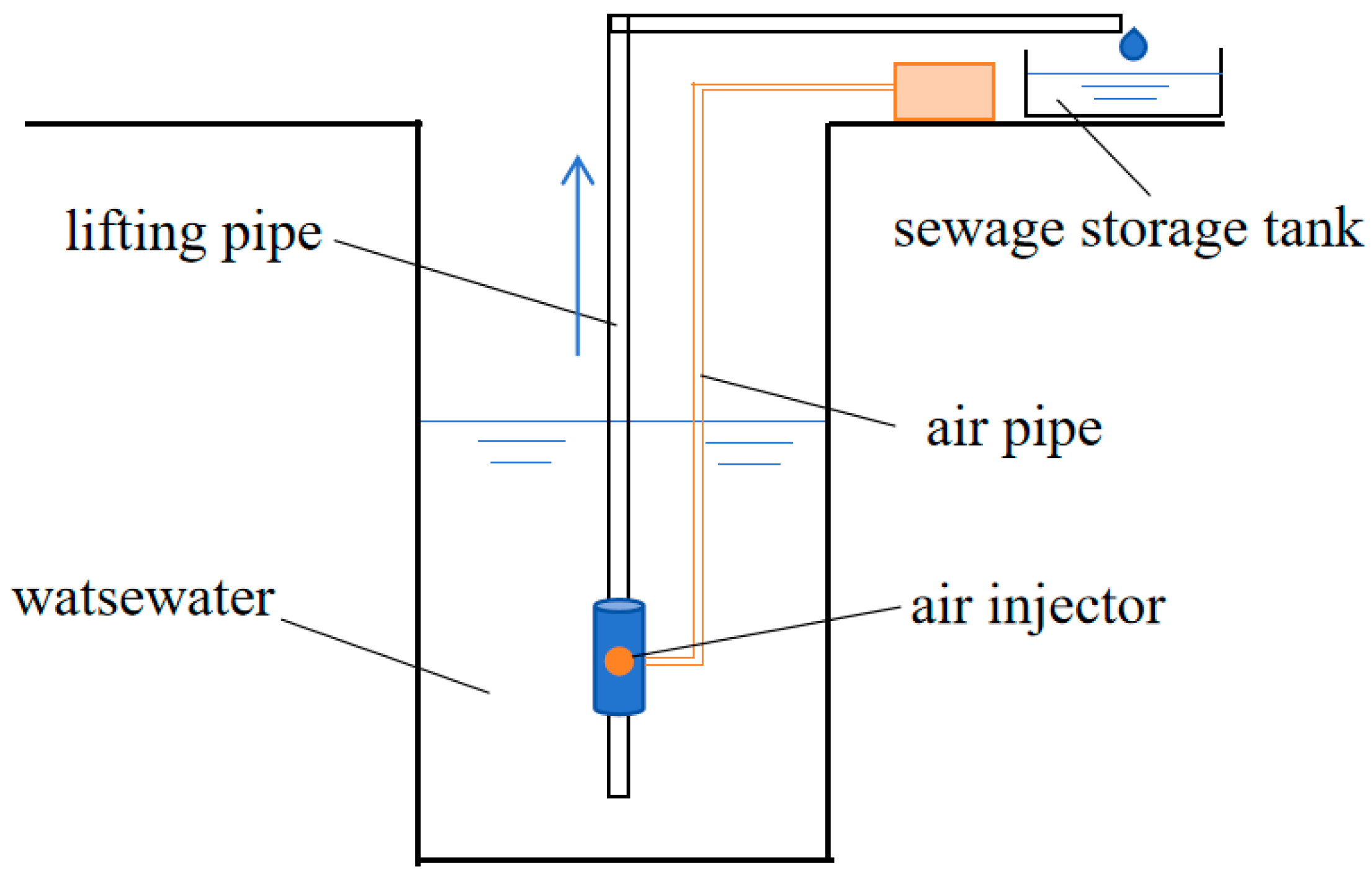
Figure 1. The process of lifting wastewater.
Water 16 02010 g001
Figure 2. The model of annular flow in the lifting pipe.
Water 16 02010 g002
Figure 3. Experimental airlift pump. The red color denote gas phase, and red arrows denote gas flow direction. The light blue denote liquid phase, and the green color denote liquid.
Water 16 02010 g003
Figure 4. High-speed photography.
Water 16 02010 g004
Figure 5. Optical path diagram.
Water 16 02010 g005
Figure 6. Image distortion correction diagram.
Water 16 02010 g006
Figure 7. Image-processing flow chart.
Water 16 02010 g007
Figure 8. Process of extracting the film thickness (JG = 10m/s, γ = 0.3). (a) Original image; (b) grayscale image; (c) binary image; (d) droplet removal.
Water 16 02010 g008
Figure 9. Result of extracting film thickness. (a) Virtual image of the interface; (b) true image of the interface.
Water 16 02010 g009
Figure 10. Image distortion of the uniform black-and-white grid in the test tube. (a) Undistorted grid and (b) distorted grid in the water medium.
Water 16 02010 g010
Figure 11. Performance curve of airlift pumps (γ = 0.3).
Water 16 02010 g011
Figure 12. Film thicknesses at different times (γ = 0.3). (a) t = 0 and (b) t = 0.28 s. The red circle area was marked to emphasize that there is an extreme peak in the position z/D = 0.8.
Water 16 02010 g012
Figure 13. Film thickness (γ = 0.3). (a) z = 0, 0.2 D, and 0.4 D; (b) z = 0.6 D, 0.8 D, and D.
Water 16 02010 g013
Figure 14. Spatial–temporal evolution of the film thickness (γ = 0.3). (a) JG = 10 m/s; (b) JG = 11 m/s.
Water 16 02010 g014
Figure 15. Mean film thickness versus gas velocity (γ=0.3).
Water 16 02010 g015
Figure 16. Mean film thickness versus submergence ratio.
Water 16 02010 g016
Disclaimer/Publisher’s Note: The statements, opinions and data contained in all publications are solely those of the individual author(s) and contributor(s) and not of MDPI and/or the editor(s). MDPI and/or the editor(s) disclaim responsibility for any injury to people or property resulting from any ideas, methods, instructions or products referred to in the content.