Article

Research on Internal Flow and Pressure Fluctuation Characteristics of Centrifugal Pumps as Turbines with Different Blade Wrap Angles

1
CNOOC China Limited, Beijing Research Center, Beijing 100028, China
2
Research Center of Fluid Machinery Engineering and Technology, Jiangsu University, Zhenjiang 212013, China
3
Wenling Fluid Machinery Technology Institute of Jiangsu University, Wenling 317525, China
*
Author to whom correspondence should be addressed.
Water 2024, 16(13), 1861; https://doi.org/10.3390/w16131861
Submission received: 15 May 2024 / Revised: 19 June 2024 / Accepted: 21 June 2024 / Published: 28 June 2024
(This article belongs to the Special Issue Design and Optimization of Fluid Machinery, 2nd Edition)

Abstract

:
The use of pumps as turbines has been gaining more and more attention in recent years. The present work mainly investigates the influence of blade wrap angle on the internal flow and pressure fluctuation characteristics of centrifugal pumps as turbines. Five different wrap angles (35°,45°, 55°, 65°, and 75°) for a forward-curved impeller were numerically analyzed under multiple operating conditions. The accuracy of numerical simulation was validated by experimental results. The results show that maximum efficiency is achieved with a blade wrap angle of 35°, and the highest efficiency flow point gradually decreases as the blade wrap angle increases. It is found by conducting entropy production theory analysis that the high-entropy production rate regions in PATs are concentrated in the volute tongue and impeller blade inlet regions, and that the entropy production rate at the impeller inlet region increases and then decreases as the blade wrap angle decreases. In addition, pressure pulsation was affected not only by dynamic and static interference but also by an irregular vortex around the impeller; its magnitude under Qt is higher than 0.8Qt for blade wrap angles of 55° and 75°. The primary frequency of pressure pulsation within the impeller is the axial frequency fn and its multiples, and the frequency with the largest amplitude is 3fn. The periodicity of vortices is closely related to the periodicity of pressure pulsation. And it is suggested that a PAT with a 35° blade wrap angle is advantageous for improving the stability of a turbine.

1. Introduction

The perpetual increase in energy demand is the foremost issue facing various aspects of today’s society, economy, and technology. The capacity to fully utilize renewable energy resources is a crucial factor in achieving sustainable development. A significant amount of high-pressure liquid energy is unnecessarily wasted in various industrial processes, such as those in petrochemicals, the coal chemical industry, sea water desalination, and steel metallurgy. With the development of liquid residual pressure energy recovery technology, surplus energy can be recuperated and effectively employed through the deployment of pumps as turbines (PATs) [1,2,3]. Turbines offer benefits such as compact dimensions, uncomplicated architecture, and cost efficacy, and facilitate manufacturing and maintenance [4]. In particular, a forward-curved blade impeller for a PAT was developed to improve the hydraulic performance of PATs.
The hydraulic efficiency of PATs is 2%, which is ~ 8.5% lower than pump operating conditions, and the high efficiency region is narrow, and the operation is unstable in PATs. Numerous scholars have begun to research PATs, focusing on improving the hydraulic performance of PATs. Yang et al. [5] carried out a study on the influence of impeller diameter on efficiency in the operating range, and found that a PAT theoretical head increased and its required pressure head decreased in accordance with increasing impeller diameter. Afterwards, they also [6] studied overall performance and unsteady pressure fields under different radial gaps between impeller tips and a volute tongue, and an optimal radial gap was found for a PAT to achieve its highest efficiency. Shahram and colleagues [7] discovered the most effective efficiency point for industrial centrifugal pumps as turbines through theoretical analysis. Ji et al. [8] performed multi-objective optimization of an impeller for improving the efficiency of PATs, and they found that blade wrap angle, blade inlet width, and number of blades have a significant impact on turbine efficiency. Punit et al. [9] developed an optimization program for the operation of radial flow centrifugal pumps as turbines, which has undergone experimental validation. Shi et al. [10] analyzed the influence of guide vane numbers on the performance of PATs. Zhang et al. [11] optimized a hydraulic model of a turbine impeller to enhance the recovery efficiency of energy recuperation turbines in seawater desalination systems, leading to amendments in both efficiency and the head. Sanjay et al. [12] investigated the influence of geometric and operational parameters on the performance of PATs, and they found that impeller trimming led to an improvement in efficiency at part-load operating conditions, and that blade rounding can lead to a 3–4% rise in efficiency at rated speed with the original impeller. Maxime et al. [13] investigated the effect of runner blade design on PAT pressure field characteristics, and found that the Rh20 model had the highest level of pressure pulsation amplitudes, while the Rh15 model had the lowest level.
However, these studies retained the pristine pump form of the turbine impeller, namely, the back-curved blade impeller, without considering the operating conditions of the pump as turbine, and thus having some circumscriptions. This type of turbine demonstrated that it has low efficiency with a narrow high-efficiency range, which obstructs its application and promotion. Therefore, more attention was paid to study PATs with a forward-curved blade, and their performance was compared with a back-curved blade. Bai et al. [1] superseded the backward-curved blade impeller with a forward-curved one, and investigated the effect of different blade wrap angles on the performance and flow characteristics of a turbine utilizing numerical simulation. Wang et al. [14] designed a special impeller with forward-curved blades to improve the performance of PATs, and it was found by comparison with the original backward-curved impellers that the experimental maximum efficiencies of special forward-curved impellers of three various specific speeds were more significantly increased, and the flow efficiency curve was flatter. In addition, they [15] also investigated one kind of special impeller with forward-curved blades, and found that the flow rate of the best efficiency point increased with extension of the blade inlet angles. Additionally, energy loss within the impeller reached the minimum if a suitable blade inlet angle was selected. Qi et al. [16] investigated a numerical comparison of the flow loss of back-curved and forward-curved blade energy instauration turbines predicated on the entropy generation theory. There is very little research mainly investigating geometric parameters on the performance of PATs with forward-curved blades. Wang et al. [17] studied the effect of blade inlet angle on the external characteristics of a forward-curved blade centrifugal pump as turbine, and found that an incrementation in the blade inlet angle caused a shift of the turbine efficiency peak to a higher flow rate.
The above research shows that more scholars were focusing on studying the influence of geometric parameters on the performance of backward-curved PATs, and also paid attention to comparing PATs with forward-curved and back-curved blades. However, in-depth research and analysis on the performance and pressure pulsation characteristics of PATs with forward-curved blades are scarce. Therefore, in this study, with all other geometric parameters kept constant, we designed six geometric models of forward-curved blades for pumps as turbines. This design involved modifications in the blade wrap angle, as shown in Figure 1. In this paper, the effects of blade wrap angle on the internal flow pattern, entropy production loss, and pressure pulsation in the blade and volute regions of PATs are investigated. This analysis provides theoretical guidance for the design of an optimal blade wrap angle.

2. Entropy Production Theory

The concept of entropy production originates from the Second Law of Thermodynamics. By quantifying the entropy production associated with flow components in a pump as turbine (PAT), unstable regions within the flow can be effectively identified, and energy losses in the flow field can be accurately delineated. Entropy production within the pump can be categorized into four distinct types: direct dissipation, turbulent dissipation, average temperature gradient, and pulsating temperature gradient [3]. Given that pumps typically use pure water as the operational medium, entropy production resulting from temperature fluctuations is relatively minor, rendering internal heat exchange negligible. Consequently, this study focuses primarily on direct dissipation and turbulent dissipation when examining flow entropy production during PAT operation.
The entropy production rate generated by the average velocity (direct dissipative entropy production rate) is calculated as follows:
S p r o , D ¯ = μ T 2 u ¯ x 2 + v ¯ y 2 + w ¯ z 2 + u ¯ y + v ¯ x 2 + u ¯ z + w ¯ x 2 + v ¯ z + w ¯ y 2
where μ is the dynamic viscosity; and u, v, and w are the three components of local velocity in the cartesian coordinate system. T is the local temperature of the fluid particle.
The entropy production rate generated by pulsation, which can be calculated according to the method proposed by FABIAN et al. [18], is calculated using the following formula:
S p r o , D = β ρ ω k T
where β = 0.09 ; ω is the frequency of turbulent vortex viscosity; ρ is fluid density; and k is the turbulent kinetic energy.
A strong wall effect exists in all entropy yields and the calculation formula of entropy yields near the wall [19] is as follows:
S p r o , W = τ υ T
where τ is wall shear force and v is the local velocity magnitude of the first grid near the wall.
The total entropy of the global computing domain is the sum of direct dissipation entropy production   Δ S p r o , D ¯ , turbulent dissipation entropy production S p r o , D , and entropy production near the wall surface S p r o , W . The entropy production of each part can be obtained by integrating the local entropy production rate as follows:
Δ S p r o , D = Δ S p r o , D ¯ + Δ S p r o , D + Δ S p r o , W
Δ S p r o , D ¯ = V S p r o , D ¯ d V
Δ S p r o , D = V S p r o , D d V
Δ S p r o , W = A S p r o , W d A
where V is the volume of the computing domain; and A is the wall area of the computing domain.

3. Geometric Model and Numerical Schemes

3.1. Pump-Turbine Model and Parameters

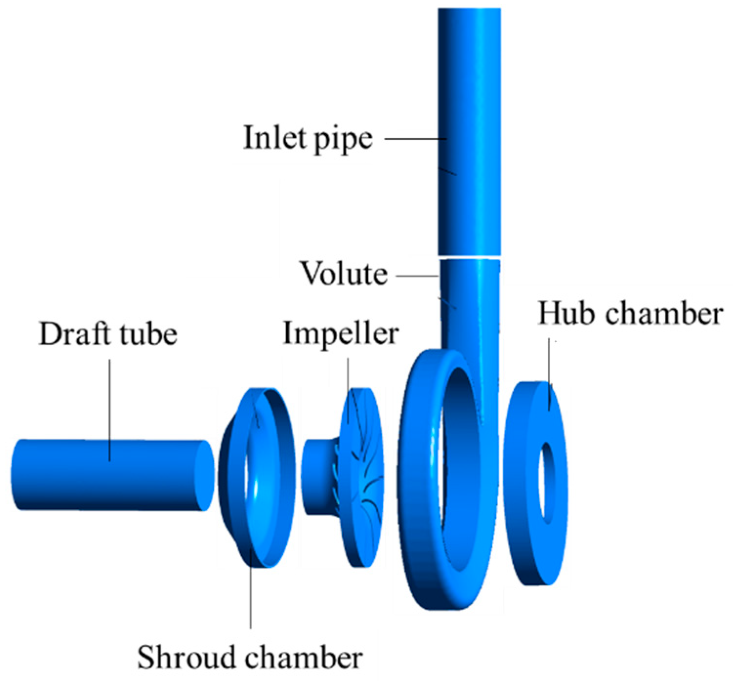
A single-stage forward-curved blade pump used as a turbine was studied. The main parameters of the impeller and volute are shown in Table 1. The hydraulic components encompass a suction chamber, shroud chamber, impeller, volute, hub chamber, and draft tube, as illustrated in Figure 2. Its basic design parameters are as follows: the design flow rate Qdes is 21.79 m3/s; the head H is 19 m; and the rated speed n is 1450 r/min.

3.2. Mesh Generation and Independence Verification

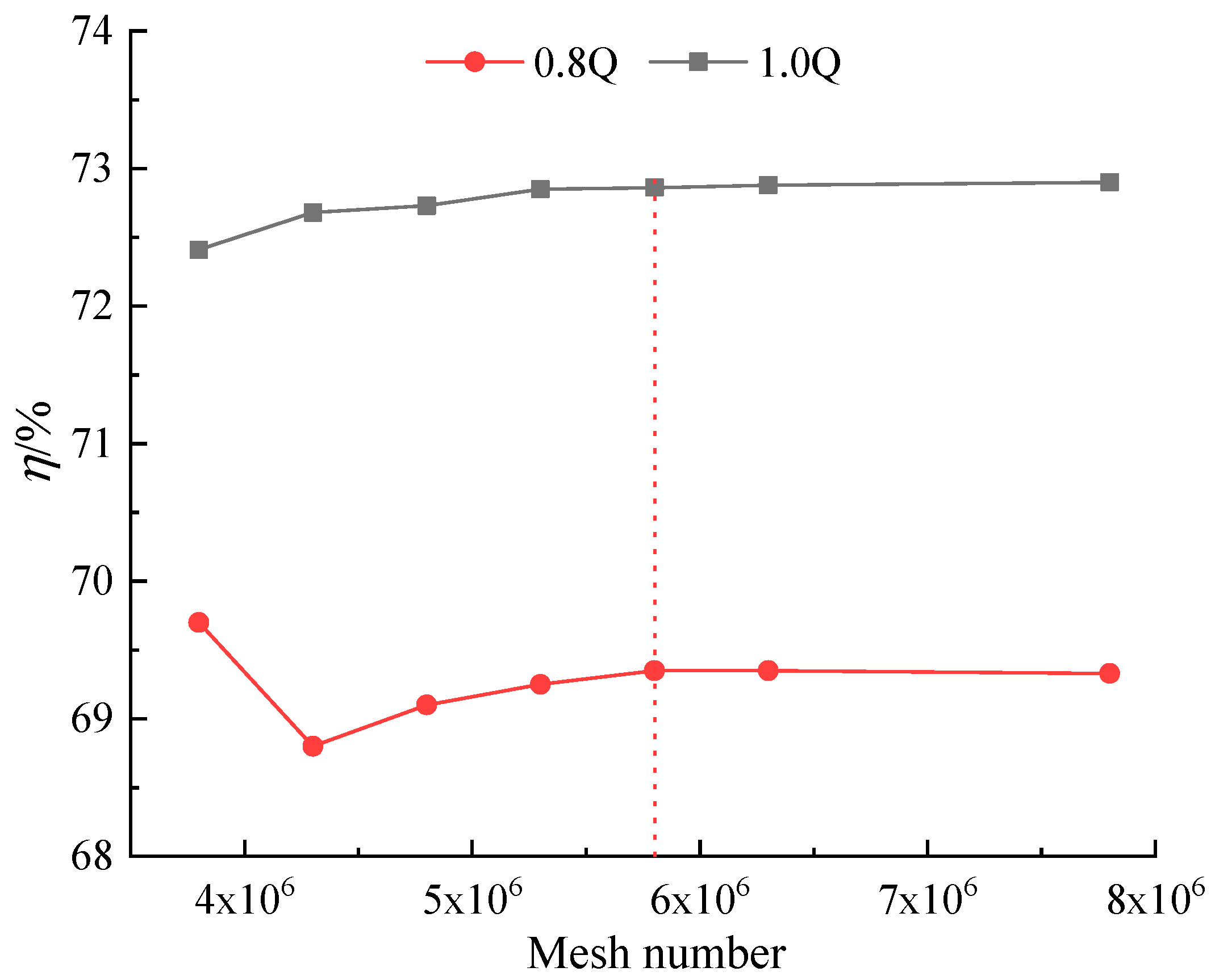
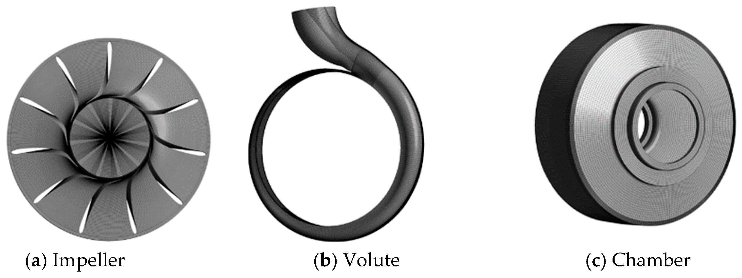
Mesh generation is a crucial step that significantly influences the accuracy of numerical calculations. In ANSYS ICEM, a hexahedral mesh structure was established to discretize the entire computational domain. Hexahedral structural meshing was performed for six calculation domains, including the inlet pipe, draft tube, shroud chamber, hub chamber, impeller, and volute. Hexahedral structured meshes can significantly reduce the number of mesh nodes and are useful for improving the accuracy of numerical simulations. Local refinement was applied to the mesh near the blade surfaces and the tongue region of the volute casing to ensure that the y+ value on the blade surface was below 50. Mesh density significantly affects the accuracy of computational results. Thus, a mesh independence study was conducted, as shown in Figure 3. It can be seen in the figure that the PAT efficiency predicted by different mesh numbers shows a convergence trend especially when the total number of mesh exceeds 5.8 million. Therefore, the error in the simulation results caused by the number of mesh variations can be ignored. Finally, considering the trade-off between computational cost and accuracy requirements, the final mesh quantity was determined to be 5.8 million, and the details of final mesh for the volute and impeller are shown in Figure 4.

3.3. Numerical Setting

Commercial CFD software, ANSYS CFX, was used to solve the steady and unsteady 3D Reynolds-averaged Navier–Stokes (RANS) equations. The SST k-ω turbulence model was utilized to calculate eddy viscosity. The boundary condition was set as follows: the total pressure was applied at the inlet of inlet pipe extension and the value was set to 1 atm; the mass flow rate was set on the outlet of the draft tube according to the operating condition; and the reference pressure was set to 0 Pa. The turbulence level on the inlet was set to medium (intensity = 5%). Additionally, the advection scheme and turbulence numeric were setting to a high-resolution scheme, which can improve the precision of the simulation. The rotating speed was set to 1450 rpm, and the rotating and stationary parts were connected using the Frozen Rotor technique for steady simulation and using transient interface for unsteady simulation. The simulation was considered to be converged when the root mean square (root mean square, RMS) of the continuity and momentum equations reached 10−5. For unsteady simulation, the time-step for transient numerical calculation was the time required for the impeller to rotate 3 degrees, which is Δ t = 3.448 × 1 0 4 s , and correspondingly, the impeller rotation requires 120 time-steps for one revolution. To investigate the transient characteristics of the internal flow field under different turbine operating conditions, considering the significant instability in the initial calculation, the calculation data of the 7th to 10th rotation of the impeller were selected for further analysis.
This research not only focuses on the operational stability of PATs under the design condition but also under part-load conditions. This is because complex flow patterns and a sudden drop in efficiency are more likely to happen under part-load conditions. Thus, flow rates of 0.8Qt and Qt were selected for further research. To explore the influence of blade wrap angle variation on the operational stability of PATs, the pressure pulsation characteristics of PATs with blade wrap angles of 35°, 55°, and 75° were investigated in detail in this research. Figure 5 shows the monitoring points P1–P8 on the impeller and volute, and the static pressure at each monitoring point was obtained by unsteady calculations. To facilitate the comparison of pressure pulsation amplitude and frequency, the pressure coefficient was defined as follows:
C p = ( p p ¯ ) / 0.5 ρ U 2
where p is instantaneous pressure, Pa; and p ¯ is the time-average pressure, Pa. ρ   is fluid density, kg/m3; and U is the impeller outlet circumferential velocity, m/s. Impeller rotation frequency fn = n/60 = 24.17 Hz; and blade frequency f is the rotation frequency of the runner, f = fn × Z = 265.83 Hz, where Z is the number of blades.

3.4. Verification of Computational Results through Experimental Studies

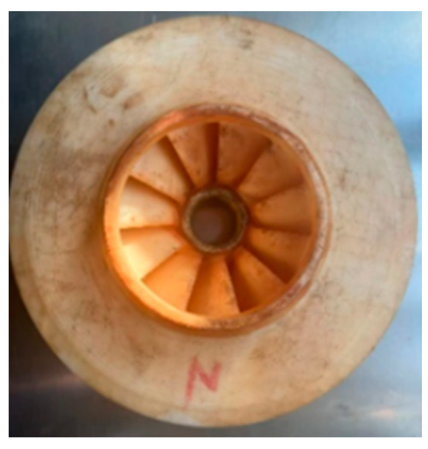
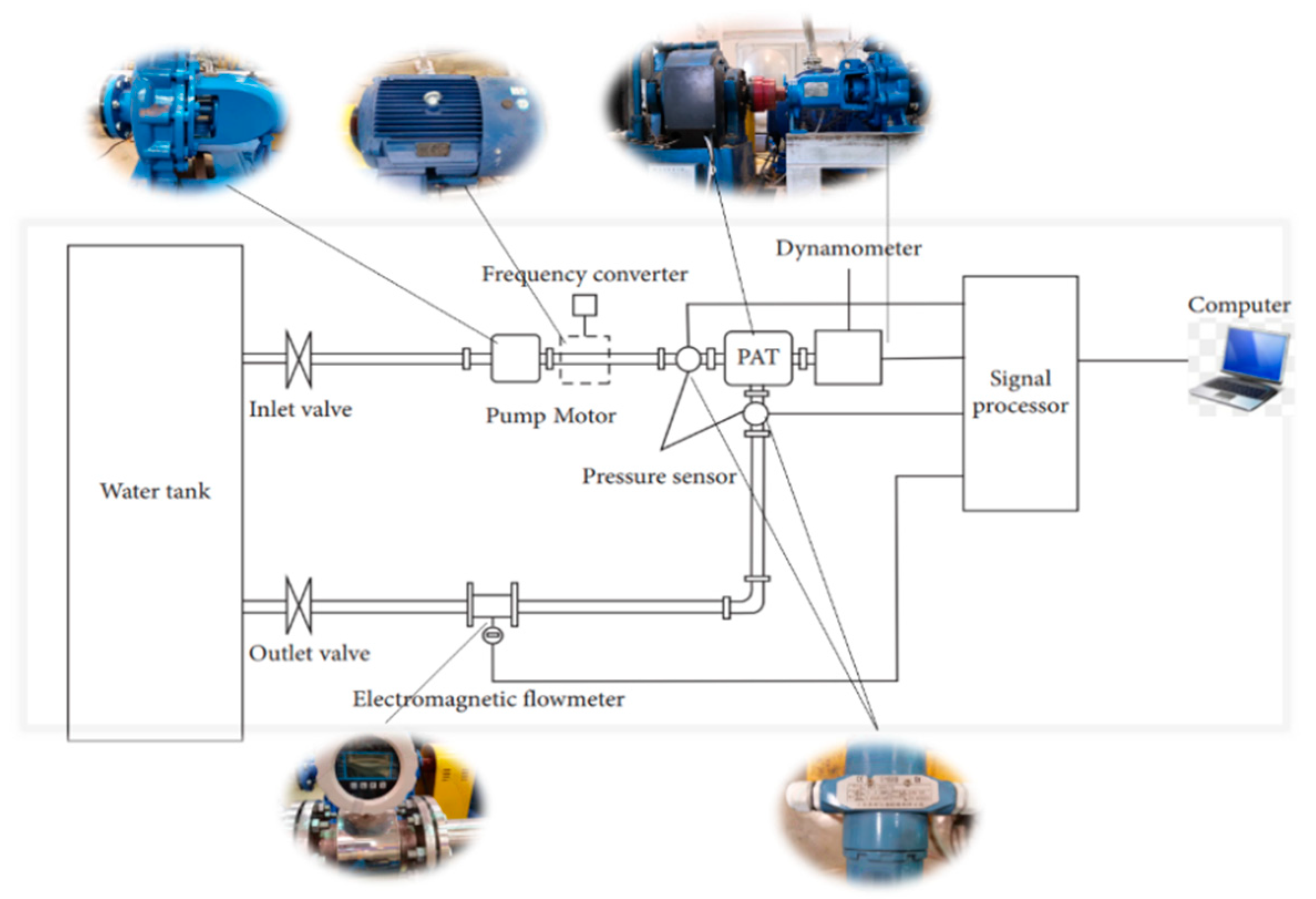
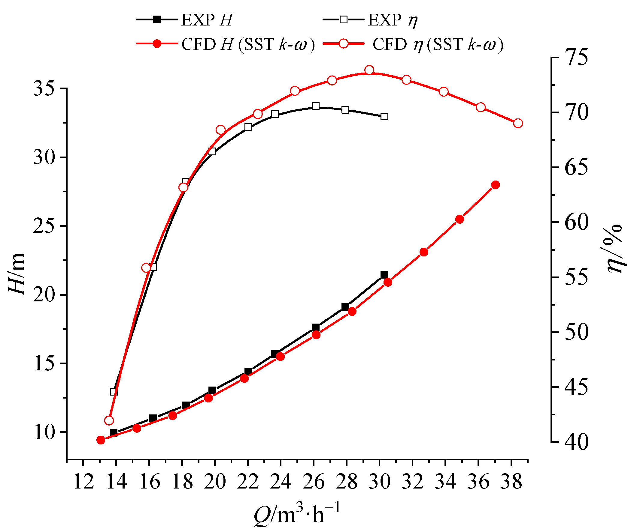
To verify the accuracy of the numerical calculations, a forward-curved impeller with a wrap angle of 35 degrees was manufactured as shown in Figure 6, and the parameters are listed in Table 1. The turbine was measured in the Fluid Machinery Engineering and Technology Research Center laboratory of Jiangsu University [20]. The experimental set-up is shown in Figure 7, and the testing equipment used during the data collection is shown in Table 2. The simulation results were compared with experimental data, as shown in Figure 8.
The head H of the turbine refers to the energy reduction per unit weight of fluid passing through the turbine, which can be calculated using the following formula:
H = P i n P o u t ρ g
where P i n is the total pressure at the turbine inlet; P o u t is the total pressure of the turbine outlet; and ρ is the density of water.
Turbine efficiency η refers to the ratio of shaft power obtained by the turbine to input power and is expressed as follows:
η = M ω ρ g Q H
where, M is the torque of the turbine; ω denotes turbine speed; and Q represents the turbine flow rate.
In Figure 8, the largest relative errors between numerical calculations and experimental results for efficiency and head are found at Q = 30.3 m3/h, which are less than 5%, and are within an acceptable range. Therefore, the numerical calculation method proposed in this paper is suitable for predicting the performance of the turbine.
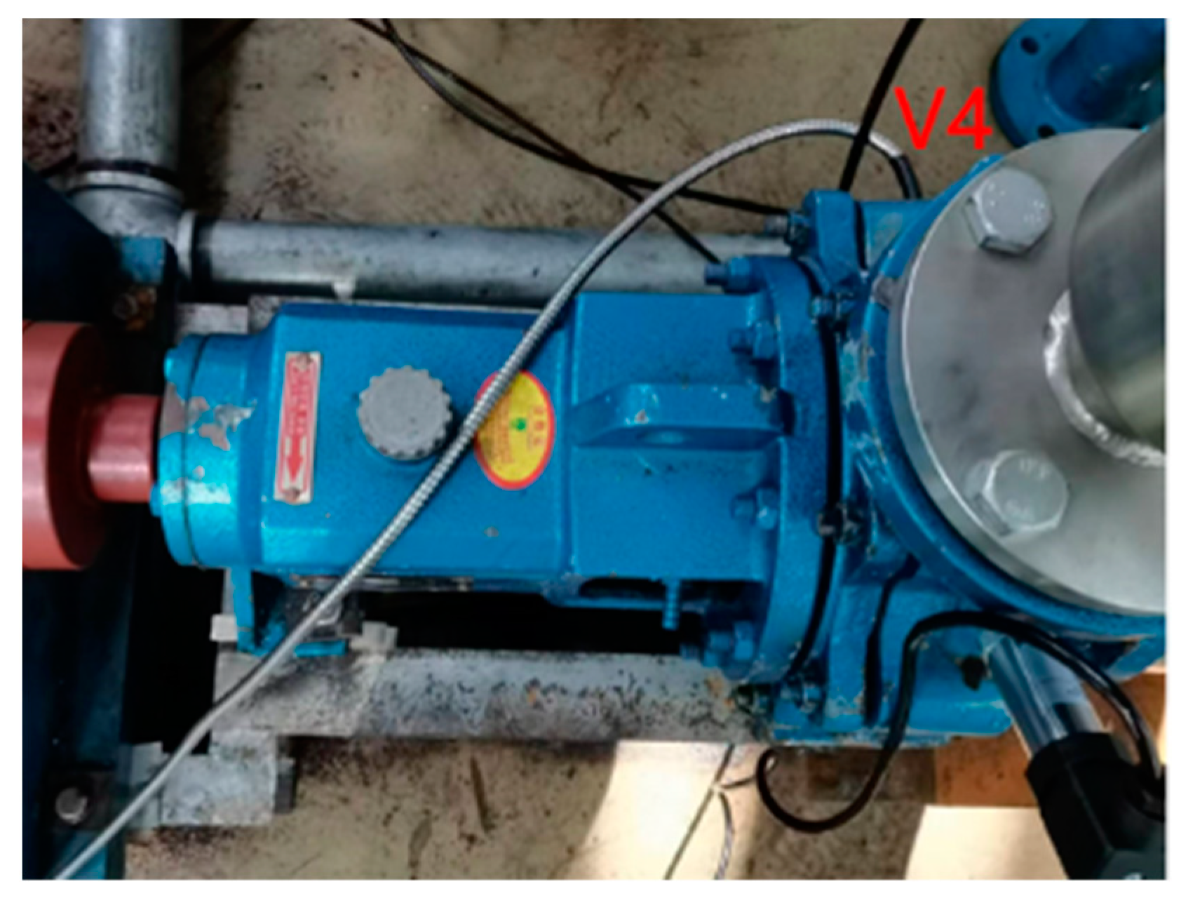
In order to ascertain the accuracy of numerical simulation in predicting pulsation characteristics, high-frequency pressure sensors were used to measure pressure pulsation characteristics by creating threaded holes on the volute wall. The pressure sensor sampling frequency was set at 2900 Hz (120 sampling points per cycle), with a sampling time of 60 s for each operating condition. The pressure pulsation sensor was installed at monitoring point V4 on the volute wall, as illustrated in Figure 9; this location corresponds to the pressure pulsation monitoring point P4. The numerical simulation results for the impeller under the Qt condition were compared with the experimental results, as depicted in Figure 10. The comparison indicates that the numerical simulation results are smaller than the experimental results, which is due to the complexity of fluid flow in the pump, and numerical simulation cannot completely capture some complex flow characteristics. However, the trends of the two curves in the figure are fundamentally consistent, with a dominant frequency of 11fn. This means that the prediction of pulsation characteristics by numerical simulation is accurate.

4. Results and Discussion

4.1. Analysis of Performance Curves

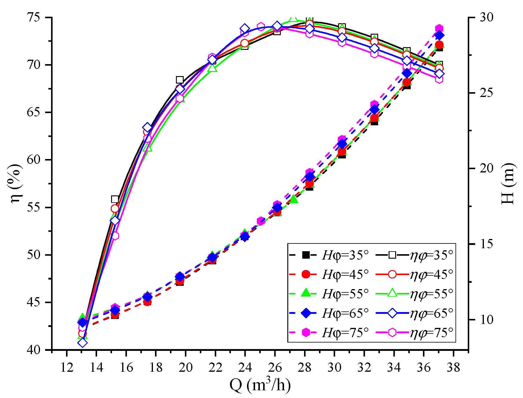
According to the numerical simulation results, performance curves of the impulse turbine with different forward-curved blade wrap angles were drawn, as shown in Figure 11. When the blade wrap angle increased from 35° to 45°, the maximum efficiency of the turbine decreased from 74.85% to 74.29%. This could be attributed to a poor match between the volute, impeller, and draft tube. Conversely, when the blade wrap angle increased from 45° to 55°, the maximum efficiency of the turbine increased from 74.29% to 74.81%. However, when the blade wrap angle increased from 55° to 75°, the maximum efficiency of the turbine decreased from 74.81% to 74.01%. In the low flow rate region, the blade wrap angle has little noticeable effect on efficiency. When the flow rate exceeds 30 m3/h, the efficiency of all design points decreases rapidly as the blade wrap angle increases. This phenomenon arises due to the blade wrap angle exceeding a particular value, causing excessive friction torque due to overly long blades, resulting in substantial impact and friction losses that negatively affect turbine efficiency.
The flow rate ranges of the high-efficiency region with various turbine wrap angles are listed in Table 3. The range of flow rates where efficiency is greater than or equal to 97% of the highest efficiency is known as the high-efficiency region. Combined with the performance curve, it can be seen that when the wrap angle increases from 35° to 55°, the high-efficiency point of the turbine shifts from 28.327 m3/h to 27.238 m3/h; however, the range of the high-efficiency region increases from 9.39 m3/h to 10.78 m3/h and then decreases to 8.1 m3/h. When the wrap angle increases from 55° to 65°, the high-efficiency point of the turbine moves from 27.238 m3/h to 26.148 m3/h, and the range of the high-efficiency region increases from 8.1 m3/h to 9.69 m3/h. As the wrap angle is raised from 65° to 75°, the high-efficiency point of the turbine moves from 26.148 m3/h to 25.059 m3/h, and the range of the high-efficiency region reduces from 9.69 m3/h to 8.89 m3/h. It is worth noting that the most substantial impact on turbine efficiency occurs when the blade wrap angle is adjusted from 45° to 55°.
Figure 12 displays the velocity streamline distribution at different mid-sections of impellers with various wrap angles when the flow rates are 0.8Qt and 1.0Qt, respectively. It can be seen from Figure 12 that the velocity streamlines distribution at different blade wrap angles and is relatively chaotic at the blade leading edge. Significant flow separation appears at the blade leading edge and causes low-velocity separation vortices. Moreover, the outlet streamline distribution is non-uniform, and the flow is relatively turbulent. By comparison, the vortex at the impeller inlet is significantly increased when the flow rate is 0.8Qt as opposed to 1.0Qt, leading to a much smoother flow. Furthermore, when the wrap angle is small, the vortex at the blade inlet is relatively stable and the flow inside the passage is also relatively smooth.
Figure 13 illustrates the pressure distribution on the axial section of different blades with varying wrap angles for flow rates of 0.8Qt and 1.0Qt. It is evident that the lowest pressure occurs at the blade outlet and working surface. As the wrap angle increases, the flow passage becomes more complex and the pressure variation stabilizes, resulting in a more uniform distribution of the low-pressure area at the blade outlet. Comparatively, the low-pressure area at the blade outlet and suction surface are significantly larger when the flow rate is 1.0 Qt in contrast to 0.8 Qt. Furthermore, as the wrap angle increases, the low-pressure area at the blade outlet shows a trend of first increasing initially and then decreasing.

4.2. Entropy Production Analysis

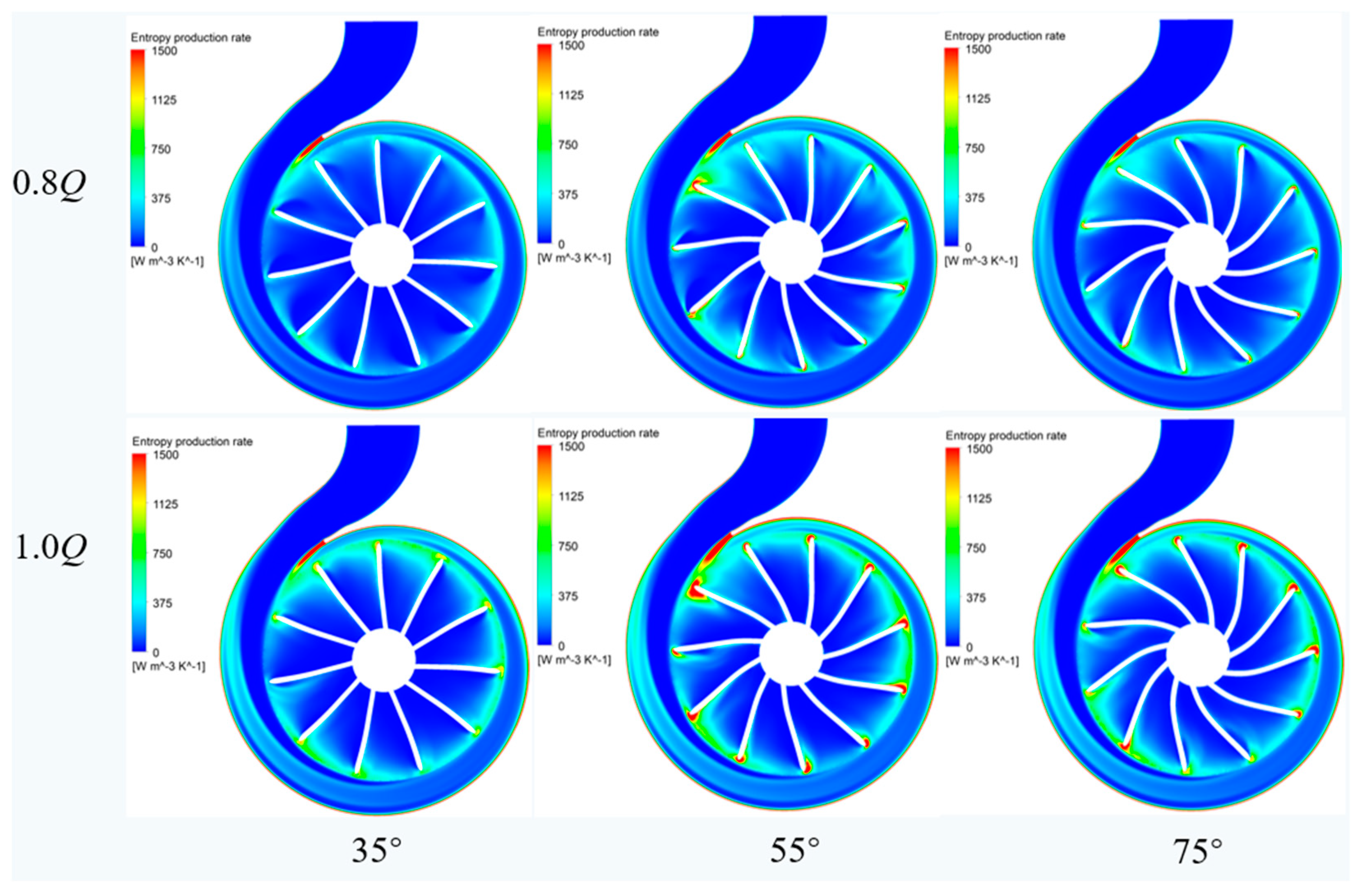
Based on the entropy production theory introduced in Section 2, the entropy production distribution in the PAT volute and impeller at different blade wrap angles was investigated in detail. The influence of different blade wrap angles on the S p r o , D in a PAT is shown in Figure 14. The energy loss mechanism in a PAT is thoroughly investigated under 0.8Qd and 1.0Qd. Overall, the distribution of the total entropy production rate inside the turbine is similar, and the entropy production rate rises with an increase in flow rate. Regions with high entropy production rates within the volute are mainly concentrated in the areas with a small cross-sectional area and near the volute tongue area. This observation indicates that the losses inside the volute are mainly focused at the volute tongue, with severe dissipation near the volute tongue. This is associated with increased turbulence loss mainly due to rotor–stator interaction effects between the volute and impeller, as well as flow separation phenomena at the volute tongue. The maximum entropy production rate occurs at the impeller inlet, and as the blade wrap angle reduces, the entropy production rate there rises initially before falling. Regions with high entropy production rates are mainly concentrated on the blade leading edge, and the turbulent entropy production rate linked to the volute tongue is more concentrated, signifying that energy loss in the impeller is mainly concentrated on the blade leading edge due to flow impact and separation phenomena.

4.3. Transient Characteristics of Pressure Pulsation

4.3.1. Circumferential Pressure Pulsation Characteristics of the Volute

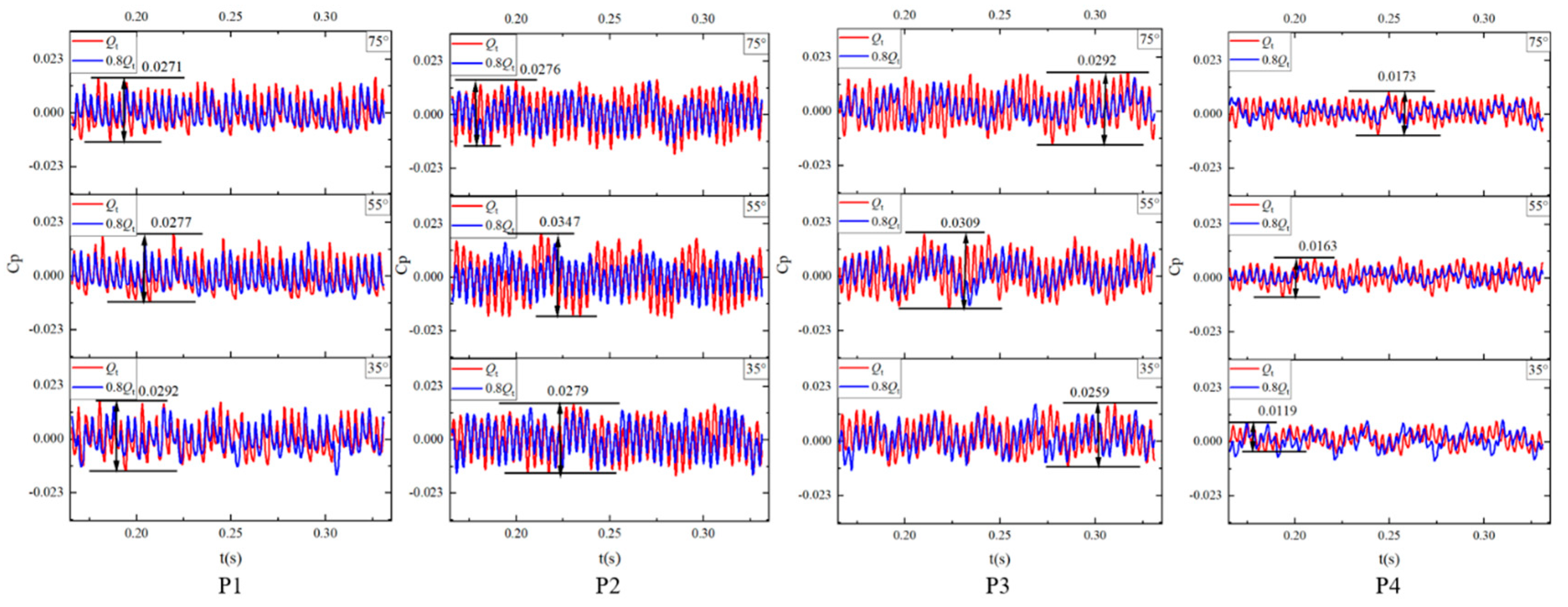
In Figure 15, the temporal distribution of pressure fluctuations at circumferential positions P1–P4 along the inner boundary of the volute casing is displayed for three blade wrap angles. The analysis covers both the 0.8Qt and 1.0Qt operational conditions as the impeller rotates from the seventh to the tenth circumferential stages. Pressure inside the volute casing exhibits a periodic variation over time for each operating condition, and pressure peaks and depressions appear 44 times in the first four impeller rotations for all three wrap angles, aligning with the number of blades on the impeller. This observation highlights the considerable influence of the impeller–volute casing interaction on circumferential pressure pulsations in the volute. The pressure pulsation amplitude at P4 is significantly reduced, mainly due to its distance from the impeller, which makes it less impacted by the interaction. The amplitude of pressure pulsations increases and stability decreases adjacent to the impeller–volute compression junction. In addition, Figure 15 reveals that the impeller with a 75° wrap angle displays a relatively smaller amplitude of pressure pulsations over four rotations. For the impeller with a 35° wrap angle, the amplitude of pressure pulsations remains nearly unchanged between the 1.0Qt and 0.8Qt operational conditions, demonstrating the stability of the volute casing with a 35° wrap angle.
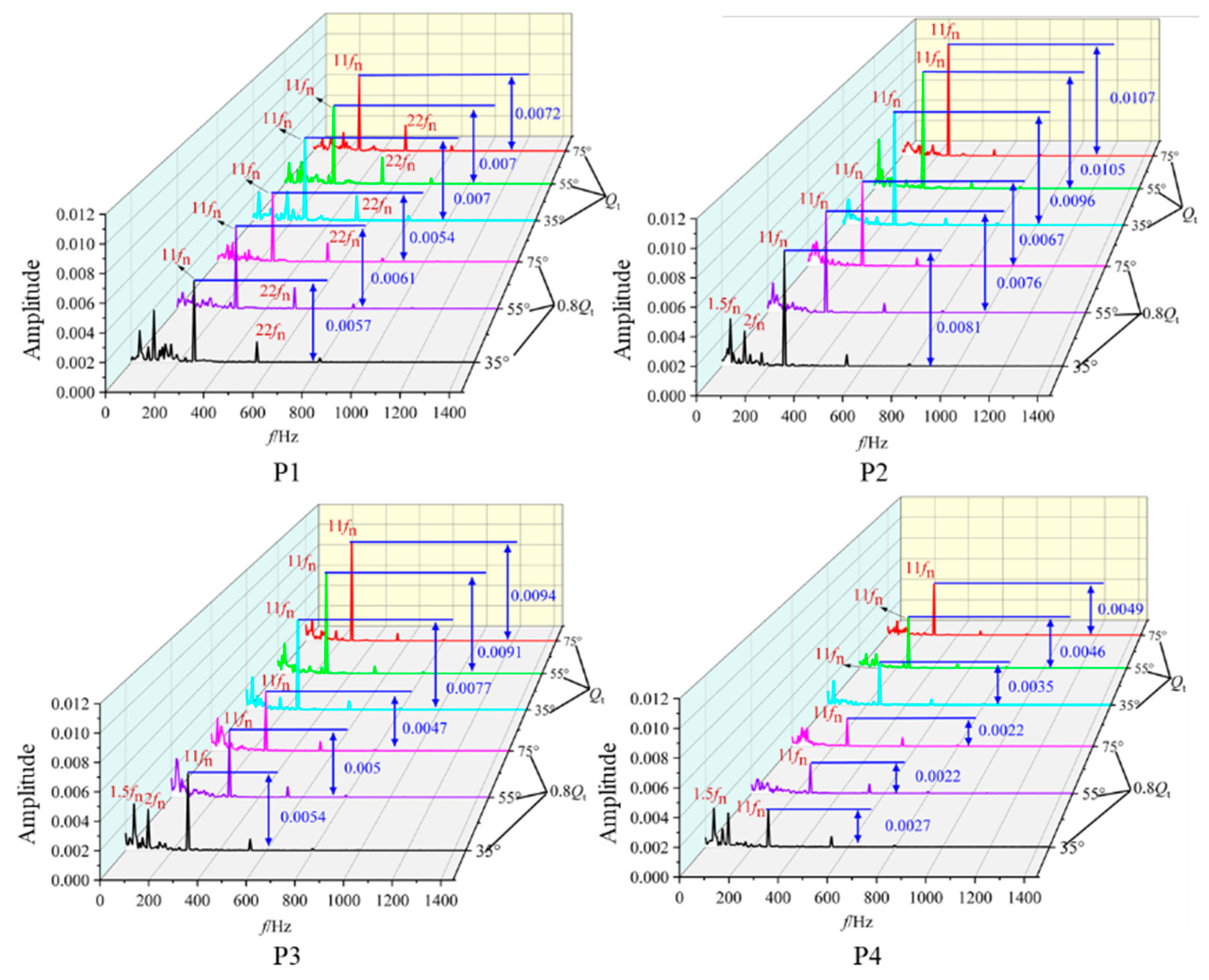
The frequency–domain distribution of pressure pulsations at the circumferential position inside the volute is shown in Figure 16. It is notable that the predominant frequency of pressure pulsations in the volute is the blade passing frequency (BPF), occurring 11 times per rotational frequency (fn), and the amplitude of the volutes oscillation generally reaches its maximum value at 11BPF. Under the 0.8Qt operating condition, the amplitudes at 1.5 fn and 2 fn increase significantly when employing a 35° blade wrap angle. This increase can be attributed to the influence of a significant backflow vortex on the pressure surface of the impeller inlet on the flow state inside the volute, as shown in Figure 10. In addition to the blade–volute interaction, the backflow vortex, which has the ability to produce low-frequency pressure pulsations with large amplitudes, also influences the pressure pulsations inside the volute. Under the Qt operating condition, the volute pressure pulsation amplitude is highest for the impeller with a 75° blade wrap angle followed by the 55°-blade-wrap-angle impeller, and is lowest for the 35°-blade-wrap-angle impeller. Conversely, this pattern reverses under the 0.8Qt operating condition. As a result, it is reasonable to conclude that the 35°-blade-wrap-angle impeller has the most stable pressure pulsations inside the volute under rated operating conditions, while the 75°-blade-wrap-angle impeller has the most stable pressure pulsations under low flow rate conditions.

4.3.2. Radial Pressure Pulsation Characteristics of the Impeller

Figure 17 presents the time domain distribution of pressure pulsations on the working surface of the impeller at radial locations P6, P7, and P8 in the middle section of the impeller flow channel. It can be obviously observed that the pressure pulsation amplitude decreases gradually from the inlet to the outlet of the impeller. Notably, the pressure pulsation amplitude is higher during the 1.0Qt operating condition compared to the 0.8Qt condition. When operating at 0.8Qt, the vibration amplitude of the impeller with a 55° wrap angle is inconsistent, and the pulsation situation gradually changes from the inlet to the outlet. Analysis of the internal flow characteristics of the impeller reveals that this behavior is a result of instability of the vortices from the impeller inlet to the outlet, where the negative pressure at the center of the vortex affects the pressure fluctuation at the trailing edge of the blade. Within the range of wrap angles examined, the impeller with a 35° wrap angle exhibits a lower pressure pulsation amplitude at all operating conditions, indicating that the impeller with a 35° wrap angle is more favorable for stable operation of the turbine.
To compare the frequency domain characteristics of the pressure pulsation in three impeller models, the frequency distribution of radial pressure pulsation within the impeller flow passage is illustrated in Figure 18. Observations from the figure indicate that the main frequency of the pressure pulsation inside the impeller is the shaft frequency or its multiple. Among the different blade wrap angles, the impeller with blade wrap angles of 35° and 75° shows a gradual reduction in pressure pulsation amplitude from the inlet to the outlet, whereas the impeller with a 55° blade wrap angle initially experiences a decrease in pressure pulsation amplitude before it starts increasing. Notably, the impeller with a 35° blade wrap angle shows the lowest amplitude among the various operating conditions, and the amplitude variation from the impeller inlet to the outlet is small. Hence, it can be inferred that the impeller with a blade wrap angle of 35° exhibits a relatively weak degree of pulsation intensity inside the centrifugal turbine, which is conducive to safe and stable operation.
In order to gain a more comprehensive understanding of the root causes behind the low-frequency signals within the impeller flow path, transient characteristics of the mid-section of the 55°-blade-wrap-angle impeller were investigated from T0 to every 1/4T rotation during operation at 0.8Qt. Here, T0 denotes a certain moment and T signifies a full rotation cycle of the impeller. Figure 19 illustrates that the vortex at the monitored point exhibits a pattern of decline followed by an increase between T0 and T0 + 3/4T, which corresponds to the decrease and then increase of the impeller pressure, as shown in Figure 18. It can be concluded that the pressure pulsation variations at different monitoring points are consistent with the previous conclusion, and the periodicity of the vortex is closely linked to the periodicity of pressure pulsation.

5. Conclusions

In this work, the internal flow and pressure fluctuation characteristics of centrifugal pumps as turbines with different blade wrap angles were investigated by conducting steady and unsteady simulations. The accuracy of numerical simulation was validated by experimental results, and the conclusions are obtained as follows:
(1) The hydrodynamic performance of centrifugal pumps as turbines, measured by their flow rate and efficiency, is notably affected by variations in blade wrap angle. When the flow rate exceeds 30 m3/h, the efficiency of all design points decreases rapidly as the blade wrap angle increases. With an increase in wrap angle, the optimal efficiency flow rate point gradually decreases. Among the five tested wrap angles, maximum efficiency is achieved with a blade wrap angle of 35°. The widest range of high efficiency region can be found with blade wrap angle of 45°. The high entropy production rate regions in PATs are concentrated in the volute tongue and impeller blade inlet regions. The entropy production rate at the impeller inlet region increases and then decreases as the blade wrap angle decreases.
(2) Pressure pulsation within the volute is influenced by the impeller, and the number of impeller blades determines the period of pressure pulsation. For the blade wrap angles of 55° and 75°, the pressure pulsation amplitude in the Qt condition is relatively higher than that in the 0.8Qt condition. The lowest pressure pulsation amplitude in the volute is observed with blade wrap angle 35° under the design condition, and with a blade wrap angle of 75° under a part-load condition. Within the impeller, the primary frequency of pressure pulsation is the shaft frequency and its harmonics. The impeller blades with a 35° wrap angle exhibit a lower pressure pulsation amplitude under all operating conditions. The pressure pulsation amplitude in the impeller inlet region is always the largest, especially under 0.8Qt.
(3) Pressure pulsation is not only affected by rotor–stator interactions but also by backflow vortices and separation vortices. The closer the interface between the volute and the impeller, the more severe the effect of the rotor–stator interaction on pressure pulsation, and the higher the pulsation amplitude. The periodicity of vortices is closely related to the periodicity of pressure pulsation. The utilization of a blade wrap angle of 35° is beneficial in improving the stability of PATs.

Author Contributions

Conceptualization, H.X. and W.A.; methodology, H.X. and W.A.; software, E.K.; validation, E.K. and Y.M.; formal analysis, Y.M.; investigation, H.X.; data curation, H.X.; writing—original draft preparation, H.X. and G.Y.; writing—review and editing, L.G.; visualization, H.X.; supervision, D.Z.; funding acquisition, L.G. All authors have read and agreed to the published version of the manuscript.

Funding

This research was funded by Taizhou City’s industrial science and technology planning projects, grant No. 22gyb41, and Jiangsu University, grant No. 21JDG052.

Data Availability Statement

The data that support the findings of this study are available from the corresponding author upon reasonable request.

Conflicts of Interest

Authors Haibo Xu, Weizheng An, Erqinhu Ke and Yingyi Ma were employed by the company CNOOC China Limited. The remaining authors declare that the research was conducted in the absence of any commercial or financial relationships that could be construed as a potential conflict of interest.

References

  1. Bai, Y.; Kong, F.; Yang, S.; Chen, K.; Dai, T. Effect of blade wrap angle in hydraulic turbine with forward-curved blades. Int. J. Hydrog. Energy 2017, 42, 18709–18717. [Google Scholar] [CrossRef]
  2. Williams, A.A.; Amiee, B.A. The Turbine Performance of Centrifugal Pumps: A Comparison of Prediction Methods. Proc. Inst. Mech. Eng. Part A J. Power Energy 2016, 208, 59–66. [Google Scholar] [CrossRef]
  3. Zhou, L.; Hang, J.; Bai, L.; Krzemianowski, Z.; El-Emam, M.; Yasser, E.; Agarwal, R. Application of entropy production theory for energy losses and other investigation in pumps and turbines: A review. Appl. Energy 2022, 318, 119211. [Google Scholar] [CrossRef]
  4. Jain, S.V.; Patel, R.N. Investigations on pump running in turbine mode: A review of the state-of-the-art. Renew. Sustain. Energy Rev. 2014, 30, 841–868. [Google Scholar] [CrossRef]
  5. Yang, S.; Liu, H.; Kong, F.; Dai, C.; Dong, L. Experimental, numerical, and theoretical research on impeller diameter influencing centrifugal pump-as-turbine. J. Energy Eng. 2013, 139, 299–307. [Google Scholar] [CrossRef]
  6. Yang, S.; Liu, H.; Kong, F.; Xia, B.; Tan, L. Effects of the radial gap between impeller tips and volute tongue influencing the performance and pressure pulsations of pump as turbine. J. Fluids Eng. 2014, 136, 054501. [Google Scholar] [CrossRef]
  7. Derakhshan, S.; Nourbakhsh, A. Theoretical, numerical and experimental investigation of centrifugal pumps in reverse operation. Exp. Therm. Fluid Sci. 2008, 32, 1620–1627. [Google Scholar] [CrossRef]
  8. Ji, Y.; Yang, Z.; Ran, J.; Li, H. Multi-objective parameter optimization of turbine impeller based on RBF neural network and NSGA-II genetic algorithm. Energy Rep. 2021, 7, 584–593. [Google Scholar] [CrossRef]
  9. Singh, P.; Nestmann, F. An optimization routine on a prediction and selection model for the turbine operation of centrifugal pumps. Exp. Therm. Fluid Sci. 2010, 34, 152–164. [Google Scholar] [CrossRef]
  10. Shi, F.X.; Yang, J.H.; Wang, X.H. Analysis on the effect of variable guide vane numbers on the performance of pump as turbine. Adv. Mech. Eng. 2018, 10, 1687814018780796. [Google Scholar] [CrossRef]
  11. Zhang, D.; Qi, B.; Zhao, R.; Zhang, Q. Optimization design of hydraulic model for seawater desalination energy recovery turbine. J. Drain. Irrig. Mach. Eng. 2021, 39, 649–654. [Google Scholar]
  12. Jain, S.V.; Swarnkar, A.; Motwani, K.H.; Patel, R.N. Effects of impeller diameter and rotational speed on performance of pump running in turbine mode. Energy Convers. Manag. 2015, 89, 808–824. [Google Scholar] [CrossRef]
  13. Binama, M.; Su, W.; Cai, W.; Li, X.; Muhirwa, A.; Li, B.; Bisengimana, E. Blade trailing edge position influencing pump as turbine (PAT) pressure field under part-load conditions. Renew. Energy 2019, 136, 33–47. [Google Scholar] [CrossRef]
  14. Wang, T.; Wang, C.; Kong, F.; Gou, Q.; Yang, S. Theoretical, experimental, and numerical study of special impeller used in turbine mode of centrifugal pump as turbine. Energy 2017, 130, 473–485. [Google Scholar] [CrossRef]
  15. Wang, T.; Kong, F.; Xia, B.; Bai, Y.; Wang, C. The method for determining blade inlet angle of special impeller using in turbine mode of centrifugal pump as turbine. Renew. Energy 2017, 109, 518–528. [Google Scholar] [CrossRef]
  16. Qi, B.; Zhang, D.; Geng, L.; Zhao, R.; van Esch, B.P.M. Numerical and experimental investigations on inflow loss in the energy recovery turbines with back-curved and front-curved impeller based on the entropy generation theory. Energy 2022, 239, 122426. [Google Scholar] [CrossRef]
  17. Wang, T.; Kong, F.; Liu, Y.; Wei, Q. Numerical simulation and validation of effects of blade inlet angle on performance of pump-as-turbine. Trans. Chin. Soc. Agric. Eng. 2017, 33, 98–104. [Google Scholar]
  18. Kock, F.; Herwig, H. Local entropy production in turbulent shear flows: A high-Reynolds number model with wall functions. Int. J. Heat Mass Transf. 2004, 47, 2205–2215. [Google Scholar] [CrossRef]
  19. Qi, B.; Bai, X.; Li, Y.; Wang, X.; Zhang, X.; Zhang, D. Research on the influence mechanism of internal flow characteristics on energy conversion in radial energy recovery turbines under multiple conditions. Energy 2024, 296, 131191. [Google Scholar] [CrossRef]
  20. Qi, B.; Zhang, D.; Li, Y.; Shen, X.; van Esch, B.P.M. A comparative study on the reducing flow rate design method for a desalination energy recovery pump as turbine. J. Braz. Soc. Mech. Sci. Eng. 2021, 43, 441. [Google Scholar] [CrossRef]
Figure 1. Diagram of forward-curved blades with different cladding angles.
Water 16 01861 g001
Figure 2. Three-dimensional diagram of the entire computing domain.
Water 16 01861 g002
Figure 3. Grid independence verification.
Water 16 01861 g003
Figure 4. Grid diagram of volute and impeller.
Water 16 01861 g004
Figure 5. Distribution of pressure pulsation monitoring points on impeller and volute.
Water 16 01861 g005
Figure 6. Diagram of impeller for testing.
Water 16 01861 g006
Figure 7. Experimental platform diagram.
Water 16 01861 g007
Figure 8. Comparison of numerical simulation and test data.
Water 16 01861 g008
Figure 9. Pressure pulsation monitoring point of the experimental apparatus.
Water 16 01861 g009
Figure 10. Comparison of numerical simulation (a), and experimental pressure pulsation (b).
Water 16 01861 g010
Figure 11. Performance curves of the turbine with varying blade wrap angles.
Water 16 01861 g011
Figure 12. Velocity streamlines distribution for varying blade wrap angles under different operating conditions.
Water 16 01861 g012
Figure 13. Pressure distribution at different blade envelope angles under different working conditions.
Water 16 01861 g013
Figure 14. The total entropy production rate of a turbine under different blade wrap angles.
Water 16 01861 g014
Figure 15. Analysis of time domain pressure fluctuations on the volute casing.
Water 16 01861 g015
Figure 16. Frequency domain analysis diagram of pressure pulsation on the volute casing.
Water 16 01861 g016
Figure 17. Radial pressure pulsation time domain analysis of impeller.
Water 16 01861 g017
Figure 18. Frequency domain analysis of radial pressure pulsation on the impeller.
Water 16 01861 g018
Figure 19. Transient characteristics of turbulent kinetic energy of a 55°-blade-angle impeller at 0.8Qt.
Water 16 01861 g019
Table 1. Design parameters of the turbine.
ComponentParametersValue
Blade of PATimpeller input diameter D1 (mm)160
inlet width b1 (mm)8
blade leading-edge angle βb2 (°)90
blade trailing-edge angle βb1 (°)30
blade wrap angle φ (°)35
number of blades Z11
impeller outlet diameter D267.2
Volutevolute base circle D3176
volute outlet width b320
Table 2. Range and precision of measuring instruments.
InstrumentTypeMeasured ParametersRangeAccuracy
Battery-powered flowmeterMEX-LDEvolume flow Q (m3/h)0–120±0.5%
Pressure transmitterMEX-3051TGinlet and outlet
pressure P (MPa)
0–1.6±0.05%
Eddy current dynamometerCWF11Dtorque M (N·m)0–35±0.4%
Speed sensor rotate speed n (r/min)0–10,000±1 r/min
Micro-dynamic pressure sensorSCYG314pressure pulsation P (Pa)0–0.8 MPa±0.5%
Table 3. Traffic range in the high-performance region.
Blade Wrap Angle (°)ηmax (%)0.97ηmax (%)Qmin (m3/h)Qmax (m3/h)Best Efficiency Range (m3/h)
3574.8572.623.733.099.39
4574.2972.0622.4333.2110.78
5574.8172.5724.4832.588.1
6574.171.8822.6932.389.69
7574.0171.7922.6731.568.89
Disclaimer/Publisher’s Note: The statements, opinions and data contained in all publications are solely those of the individual author(s) and contributor(s) and not of MDPI and/or the editor(s). MDPI and/or the editor(s) disclaim responsibility for any injury to people or property resulting from any ideas, methods, instructions or products referred to in the content.