Abstract
Fluid sloshing within containers subjected to external motion is a crucial yet intricate phenomenon with implications across various industries. This study investigates sloshing in a rectangular liquid tank through a series of experiments examining pitch excitations with diverse excitation frequencies and amplitudes across different liquid carrying rates. By analyzing pressure data and imagery of the free liquid surface, statistical trends in peak pressure at measurement points within the tank are identified, revealing the nonlinear behavior of the fluid. Spectral analysis generates power spectrum curves that delineate frequency components and energy distribution within the sloshing dynamics. Key findings include the identification of resonance-induced violent sloshing at a 20% liquid-carrying rate and a resonant frequency shift at a 70% liquid-carrying rate due to nonlinearity, displaying a “soft spring” characteristic in the frequency response. The free liquid surface exhibits four distinct waveforms depending on frequency. Notably, at a 70% liquid-carrying rate and resonant frequency excitation, three-dimensional vortex waves emerge, highlighting a complex three-dimensional effect within the tank. The power spectrum shows that the dominant response frequency aligns with the excitation frequency and its multiples. This investigation enhances our understanding of the intricate nature of sloshing in various liquid-carrying conditions, offering insights valuable for diverse industrial applications.
1. Introduction
Sloshing is a complex flow phenomenon that occurs when a partially filled liquid container is subjected to forced motion due to external excitation. The sloshing phenomenon carries immense practical significance across diverse industries, such as aerospace, oil and gas storage, and transportation. In maritime contexts, sloshing may impair ship stability and even lead to the capsizing of the ship. In addition, sloshing may induce substantial dynamic pressures on the liquid container structure, posing a threat to structural safety. Thus, considerable attention is directed toward understanding liquid sloshing dynamics and addressing the associated impact pressures.
The experimental method serves as an important tool for understanding the intricacies of liquid sloshing, elucidating its characteristics, and assessing the impact of external variables. Based on their experiments, Faltinsen et al. [1,2] extensively analyzed transient wave characteristics, amplitude transitions, and structural responses, offering crucial insights into the intricate behavior of sloshing dynamics. Similarly, Wei et al. [3] delved into statistical distributions of sloshing pressures under diverse motion amplitudes and frequencies, shedding light on pressure saturation features, while Jiang et al. [4] focused on wave height and structural dynamic responses, particularly noting differences in elastic and rigid tank behavior under both resonant and non-resonant conditions. Moreover, Bulian et al. [5] pinpointed transient and steady-state regions in sloshing tests by statistical analyses, illuminating unstable states and correlations between impacts, and Delorme [6] highlighted the impact of sloshing waves on tank walls and the correlation with trapped gas at low liquid levels by testing with reduced-sloshing liquid tanks. Saltari et al. [7] discussed the experimental characterization of the vertical sloshing dissipative behavior of rectangular tanks, showing that the obtained time histories of measured accelerations and dynamic forces are directly related to the energy dissipated by the impact fluid. Qiu et al. [8] investigated the hydrodynamic performance of fluid sloshing in cryogenic fuel storage tanks using the volume of fluid (VOF) method, and analyzed the effect of initial filling level on fluid sloshing. Lin et al. [9] proposed the Local Trefftz Method (LTM) to simulate the sloshing in a two-dimensional numerical liquid tank, and investigated the effect of different excitation modes and parameters on the deformation of a fluid-free surface. Bardazzi et al. [10] investigated fluid sloshing in a horizontally oscillating cuboid tank at a wide range of excitation frequencies for a liquid-carrying rate close to the critical depth and two motion amplitudes.
Understanding the features of sloshing waveforms has been a focal point in sloshing studies [11]. Olsen and Johnsen [12] identified five distinct wave patterns exhibited by free liquid surfaces as excitation frequencies varied, offering comprehensive insights into wave behavior. Gurusamy and Kumar [13] examined sloshing frequency within shallow-water tanks under varying excitation amplitudes, elucidating phenomena like diagonal and vortex waves around resonance regions. Ibrahim [14] highlighted phase transitions in multiphase flows during liquid sloshing and their impacts on rigid walls and liquid tanks.
Shape-based influences on sloshing characteristics have been explored by researchers such as Liu et al. [15], Kim et al. [16], and Bunnik and Huijsmans [17]. Liu et al. [15] specifically focused on waveform characteristics and sloshing pressure frequency–time distribution in LNG tank models during longitudinal oscillation. Kim et al. [16] highlighted irregularities in pressure peaks and flow patterns with varying amplitudes, notably observing increased bubble formation and splashing with higher amplitudes. Bunnik and Huijsmans [17] illustrated various phenomena like shallow water surges, air pockets, and roof impacts in experiments involving complex motion patterns of prismatic capsules. Luo et al. [18] studied the effects of pulse-like ground motion on the sloshing effect and hydrodynamic pressure of large-scale liquefied natural gas (LNG) storage tanks based on the numerical simulation methods of direct coupling method and bidirectional coupling method.
Despite these extensive studies on localized sloshing phenomena, systematic experimental investigations of the sloshing in terms of the impact pressure, waveform characteristics, and spectral properties with a large-scale liquid tank are relatively less reported. In this paper, a series of detailed experiments was carried out in a large rectangular tank with different liquid-carrying rates. The nonlinear characteristics of impact pressure and sloshing waveforms were investigated in correlation with the excitation frequency and amplitude. In particular, based on the existing theories of sloshing, various waveforms, flip modes, and liquid topping phenomena were all observed. The identification of these sloshing phenomena reveals the nonlinear behavior of the sloshing process. In addition, based on the spectral analysis, the frequency components and the energy distribution characteristics of the impact pressure are studied in depth, and the energy dissipation behavior of the sloshing under prolonged excitation is explored.
2. Model Test System
2.1. Test Setup
The present model tests were conducted in the Heavy Equipment Laboratory of Jiangsu University of Science and Technology, and the test setup consisted of a rectangular liquid tank, a motion control device, a high-speed camera (Photron (Shanghai) Limited, Shanghai, China), and a data acquisition system.
Figure 1 demonstrates the top, front, and side views of the model liquid tank with locations of pressure monitoring points. The model liquid tank, which is made of Plexiglas with a thickness of 20 mm, has internal dimensions of a length L = 1000 mm, a width B = 500 mm, and a height H = 1000 mm. Water was selected as the filling liquid of the tank, while rhodamine B reagent was added for vivid red coloring (without altering the density and viscosity of water), so as to facilitate the monitoring of the movement of the free liquid surface using the high-speed camera. To record the sloshing pressures at various liquid-carrying heights, pressure monitoring points were strategically positioned on the right wall and the top of the liquid tank, as illustrated in Figure 1.
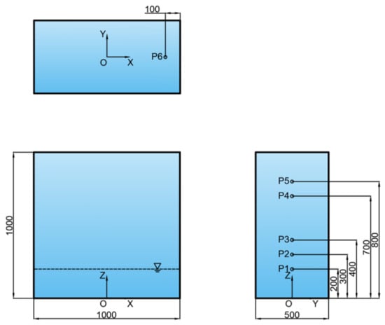
Figure 1.
Top, front, and side views for the model liquid tank with arrangement of pressure monitoring points.
The sloshing experimental system is shown in Figure 2. The experimental motion platform, which is a 3 DOF (degree-of-freedom) shaking table coupled with a control system, can simulate roll angles within ±30°, pitch angles within ±15°, and heave displacements within ±0.35 m. It offers high precision, with accuracies of 0.05° and 0.05 mm for rotational and translational motions, respectively. The platform features a substantial bearing capacity, supporting a maximum of 7 tons within a spacious 2 m × 4 m platform. In the present experiment, a pitch motion of X(t) = Asin(2πft), where A is the pitch amplitude, and f is the motion frequency, was applied to the motion platform, which induced the same motion to the liquid tank securely fixed on the platform.
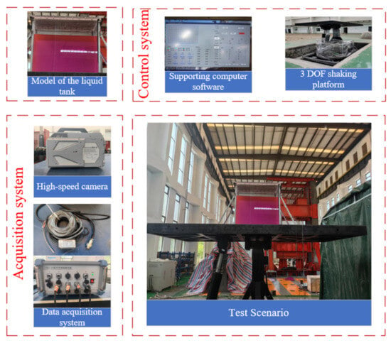
Figure 2.
Operational diagram of the sloshing test system.
Data acquisition is facilitated by a comprehensive system comprising a CY302 miniature intelligent pressure transducer (Chengdu Taisite Electronics Information Co., Ltd., Chengdu, China), RS485-20 intelligent hub, and the TST-SmartSensor 4.10 data acquisition software. The pressure transducer features a measuring range of 0–200 kPa, a sampling frequency of 1 kHz, a response time of 0.1 ms, and an accuracy rating of 0.1% Full Scale (FS). Japanese FASTCAM SA-Z high-speed cameras, equipped with a resolution of 1024 × 1024 pixels, offer an imaging capability of a minimum exposure time of 159 nanoseconds and a maximum frame rate of 200,000 frames per second. The comprehensive schematic of the sloshing test setup can be found in Figure 2, ensuring the meticulous recording of liquid movement throughout the sloshing process.
2.2. Test Cases
When the external excitation frequency is close to the resonance frequency of the liquid-carrying tank, the liquid sloshing becomes most severe and a strong nonlinearity emerges, resulting in a substantial increase in the sloshing pressures. This resonance frequency, furthermore, is recognized as a critical parameter for the design of liquid tanks, carrying inherent significance in terms of structural integrity [19].
In the context of our experiment, the test strategy is anchored to the theoretical resonance frequency of the liquid tank, specifically the first-order theoretical resonance frequency. A range of external excitation frequencies spanning 0.8 to 1.2 times the first-order theoretical resonance frequency was used, to cover both the resonant and non-resonant sloshing cases. The resonance frequency for the two-dimensional rectangular liquid sloshing, as per the formula [20], underpins our calculation process
where fn denotes the nth-order resonant frequency of the sloshing; h denotes the liquid height in the tank; L denotes the length of the liquid tank.
From Equation (1), it is seen that the liquid-carrying rate is an important parameter influencing the sloshing resonance frequency. In the present study, three liquid-carrying rates of 20%H, 30%H, and 70%H are selected, which are identified as the shallow liquid-carrying rate, the near-critical liquid-carrying rate, and the high liquid-carrying rate referring to Faltinsen and Timokha [1] and Wei et al. [3].
To validate the sloshing test setups, the first natural frequencies of sloshing at different liquid-carrying rates were measured and compared to those theoretical values obtained from Equation (1). To measure the resonant sloshing frequency, an initial perturbation was introduced to the liquid tank, allowing the liquid to undergo free decay under the influence of gravity. By employing fast Fourier analysis (FFT) on the time history curve of the sloshing pressure at a designated measurement point on the free liquid surface, frequency spectra were obtained, as illustrated in Figure 3. The peaks in the frequency spectrum demonstrate the resonant frequencies of the sloshing. A comparison of theoretical and experimental outcomes for the first-order sloshing resonant frequency, as detailed in Table 1, consistently affirms the resonance frequency’s uniformity across various liquid-carrying rates, establishing a dependable foundation for experimental case design. The test cases are divided into cases of equal-amplitude pitch and varied-amplitude pitch to discern the impact of different control parameters, as outlined in Table 2.

Figure 3.
Frequency spectra of free decaying motion for each liquid-carrying rate: (a) 20% liquid-carrying rate; (b) 30% liquid-carrying rate; (c) 70% liquid-carrying rate.

Table 1.
Comparison of theoretical and experimental first-order resonance frequencies at each liquid-carrying rate.

Table 2.
Test cases.
To ensure the robustness of the tests, a meticulous repetition for each set of test cases was performed. As an illustration of this repetition at the same parameter settings, Figure 4 shows the impact pressures and spectra of P1 for the specific case of h = 30%H, A = 2°, and f = 0.76 Hz. The time history curves of the impact pressure exhibit an impressive alignment in terms of both phase and pressure values. The peak values of all frequency components are in good agreement in the spectral analysis. Figure 5 illustrates the boxplots of the peak pressure statistics for two repetitions at different measurement points under different operating conditions. Peak pressures occurring over multiple motion periods typically demonstrate scatter, so boxplots are used to statistically analyze peak pressures over the entire sampling time to reduce the impact of quantitative analysis by the randomness of the distribution of the sloshing pressure. Each column in the boxplot signifies a set of peak pressure values. Within each column, the box depicts the range between the first and third quartiles of these peak pressures, commonly referred to as the interquartile range (IQR). From the box, whiskers extend to peak pressures located within 1.5 times the IQR. All peak pressures above this value are marked with a black circle, which shows the probability of exceedance of the pressure peaks. The peak pressures at the same measurement points under two repetitions are at the same level in terms of median and mean values. However, due to uncertainties, small variations in the peak pressure values appear in the outliers, which are associated with severe sloshing and accompanying air entrainment. The overall conclusion highlights the high degree of test repeatability.

Figure 4.
Comparison of the results of two repetitive tests at h = 30%H, A = 2°, f = 0.76 Hz condition: (a) Impact pressure for 40 s; (b) Amplitude spectrum for the entire sampling time.
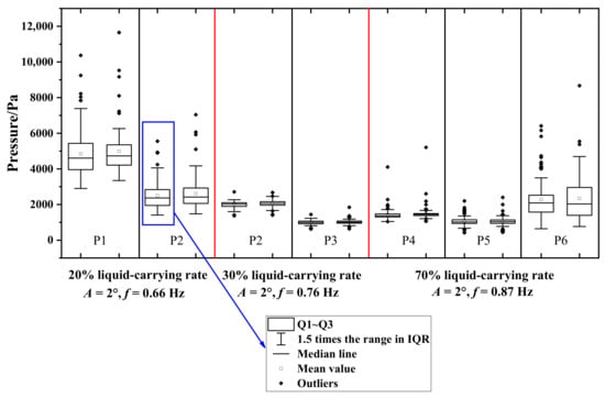
Figure 5.
The repeatability of the pressures measured by the sensors at different measuring points with different liquid-carrying rates was examined by repeating the test two times.
3. Test Results and Analysis
3.1. Sloshing Pressures
The sloshing pressure is a matter of widespread engineering concern [21], as the violent motion of liquid in the liquid tank produces large sloshing pressures on the bulkhead structure when resonant sloshing occurs. In this section, the impact pressures at and above the free liquid surface are measured to investigate the sloshing pressure characteristics at different excitation frequencies (Equal amplitude pitch) and different excitation amplitudes (Variable amplitude pitch).
Figure 6 presents the statistics of the sloshing pressures at a 20% liquid-carrying rate. The analysis focuses on pressures at two monitoring points, namely, P1 and P2. P1 is situated at the still-free surface level, while P2 is located 10 cm above the still-free surface. The average value of each column is connected by a dotted line in the figure to show the trend of peak pressures. As can be seen from Figure 6a, when excitation frequencies are far from the resonant frequency (say f = 0.53 Hz (0.8 f1) and f = 0.79 Hz (1.2 f1)), the sloshing fails to reach the P2 measurement point. When the excitation frequency is close to the resonance frequency, the wave amplitude increases, and a continuous sloshing pressure is detected at the P2 measurement point. During the sloshing, the P1 measurement point experiences significantly larger impact pressures compared to the P2 measurement point, indicating the severity of the sloshing pressures at the free liquid surface. When the excitation frequency approaches the resonance frequency, the pressures at both P1 and P2 increase significantly. The box length increases consequently. Outliers appear in the peak pressures and are concentrated on the side of larger values. The increase in box length reflects a greater scatter of the peak pressure data. The distribution of the peak pressures is the most dispersive at the resonance frequency. This indicates that the sloshing in the liquid tank is most intense at the resonance frequency. From Figure 6b, it can be seen that the increase in the pitch motion amplitude enhances the sloshing pressures, and has a significant effect on the sloshing pressure at P1. This results in a maximum value of sloshing pressure at the free surface level at A = 3°, f = 0.66 Hz (1.0 f1) as expected.
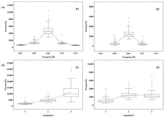
Figure 6.
Statistical distribution of peak pressures (20%H): (a) Equal amplitude pitch; (b) Variable amplitude pitch.
The statistics of the sloshing pressures at a 30% liquid-carrying rate are shown in Figure 7. For this liquid-carrying rate, P2 is located at the still-free surface, while P3 is 10 cm above the still-free surface. From Figure 7a, it can be seen that the variation in the box length with the excitation frequency is not significant, which is related to the overall level of the sloshing pressure. When the excitation frequency is close to the resonance frequency, the dispersion of the peak pressure is small, indicating a mild sloshing phenomenon. In the non-resonant condition (at f = 0.61 Hz (0.8 f1) and f = 0.68 Hz (0.9 f1)), the sloshing pressure at the P2 measurement point is similar and less affected by the excitation frequency. Near the resonance frequency (at f = 0.68 Hz (0.9 f1) and at f = 0.84 Hz (1.1 f1)), a sustained sloshing pressure starts to appear at the P3 measurement point, indicating an increase in the sloshing wave amplitude. Compared to the f = 0.61 Hz (0.8 f1) condition, at f = 0.84 Hz (1.1 f1), the sloshing has a larger wave amplitude while the sloshing pressure is smaller, indicating that the wave amplitude is not positively correlated with the size of the sloshing pressure at the P2 measurement point. From Figure 7b, it can be seen that the dispersion of the peak pressure becomes larger by increasing the pitching motion amplitude, and the trends of the P2 and P3 measurement points are consistent.
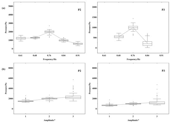
Figure 7.
Statistical distribution of peak pressures (30%H): (a) Equal amplitude pitch; (b) Variable amplitude pitch.
The statistics of the sloshing pressures at a 70% liquid-carrying rate are shown in Figure 8. For this liquid-carrying rate, P4 is located at the still-free surface, P5 is located 10 cm above the still-free surface, and P6 is located 10 cm from the right bulkhead at the roof. As can be seen in Figure 8a, the maximum sloshing pressure occurs at a liquid-carrying rate of 70% when f = 0.78 Hz (0.9 f1). This is due to the change in liquid-carrying rate, the pressure-frequency response is a “soft-spring” characteristic, and the resonance frequency is shifted to a side less than the theoretical intrinsic frequency. This phenomenon was also observed in the study [22], where the maximum response frequency decreased from 1.18 f1 to 0.92 f1 as the filling level changed and the water depth shifted from a “soft-spring” response to a “soft-spring” response. At f = 0.87 Hz (1.0 f1), the sloshing pressures at the P4, P5, and P6 measurement points are less than the f = 0.78 Hz (0.9 f1) condition, which reflects the fact that near the resonance frequency is the range of excitation frequency that should be taken into account. When the excitation frequency is gradually increased, the sloshing pressure and wave amplitude gradually decrease. When the excitation frequency is increased to f = 1.04 Hz (1.2 f1), the sloshing amplitude is not sufficient to impact the P5 and P6 measurement points, the sloshing pressure decreases significantly and tends to saturation. From Figure 8b, it can be seen that the phenomenon of liquid roofing is prone to occur under a high liquid-carrying rate. Under the conditions of A = 2° and 3°, f = 0.87 Hz (1.0 f1), the top of the tank is subjected to a significantly larger sloshing pressure than the other two measurement points. Using the statistical value of the sloshing pressure at the point of measurement, we can see that the sloshing of the basic mode for the liquid first slammed to the free surface at the point of measurement, and then the water body continued to climb, with the liquid reaching the vicinity of the top of the tank and violently slamming the top of the tank, forming splashes and jets at the moment of maximum velocity of the liquid tank. At the resonance frequency, the effect of increasing the amplitude of the pitching motion on the dispersion of the peak pressure is significant, with a significant increase in box length.
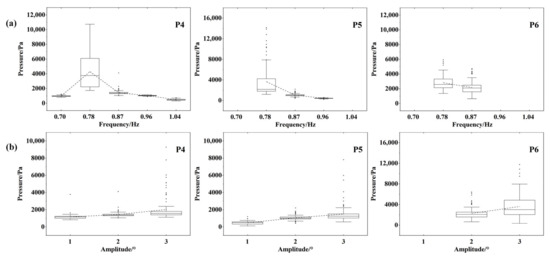
Figure 8.
Statistical distribution of peak pressures (70%H): (a) Equal amplitude pitch; (b) Variable amplitude pitch.
The comparison of sloshing pressures at the free liquid level at different liquid-carrying rates is given in Figure 9. From the mean value of the statistical pressures, the maximum sloshing pressure at the free liquid level is observed at a 20% liquid-carrying rate. The sloshing pressure at a 20% liquid-carrying rate was more than 30% higher than the other carrying rates. The smallest sloshing pressure at the free surface was observed at a 70% liquid-carrying rate, which is caused by the shift of the actual resonant frequency from the theoretical resonant frequency. As the amplitude of the sloshing increases from 1° to 3°, the sloshing pressure at a 20% liquid-carrying rate increases much more than the other carrying rates. Due to the highly nonlinear effect of the crushing wave impact, it is reasonable to have large outliers in the long-time simulation. The maximum sloshing pressures at the free liquid level are 6517.4 Pa, 10,371 Pa, and 31,607 Pa for excitation amplitudes of 1°, 2°, and 3°, respectively. This is worth using as a reference basis for the pressure design of the liquid tank.

Figure 9.
Comparison results of sloshing pressures at the free liquid surface at different liquid-carrying rates.
3.2. Waveform Characteristics of Sloshing
Flows at resonant conditions at shallow, intermediate, and high liquid-carrying rates are significantly different. At shallow liquid-carrying rates, the hydraulic jumps may occur in the liquid tank. At intermediate and critical liquid-carrying rates, breaking waves are more likely to occur in the liquid tank [23], while at high liquid-carrying rates, the sloshing is feathered with liquid roofing. In this section, waveform characterization is performed based on the experimental findings of Olsen and Johnsen [12] (five wave patterns occurring as the sloshing changes with the excitation frequency, see Figure 10), Lugni et al. [24] (three flip modes of the liquid hitting the wall, see Figure 11), and Faltinsen [25] (three roof-hitting flows, see Figure 12). For this wave pattern analysis, a stable sloshing period is chosen with the flow motion starting from the equilibrium position (0T) of the liquid tank moving clockwise downward, and returning to the equilibrium position (1T) after one cycle.
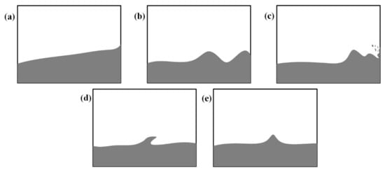
Figure 10.
Five wave patterns [12]: (a) standing wave; (b) unbroken traveling wave; (c) traveling wave breaking near the bulkhead; (d) hydraulic jumps; (e) solitary wave.

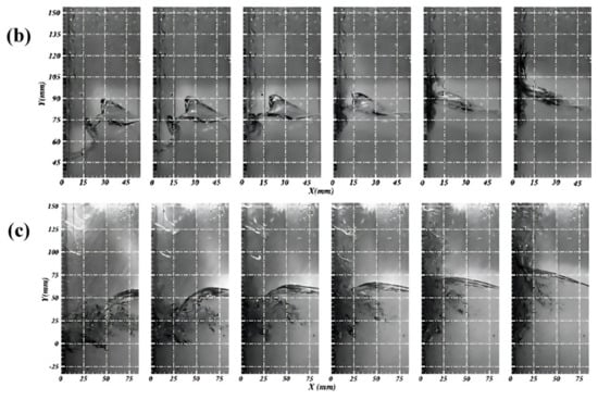
Figure 11.
Three flip modes [24]: (a) Impact of an incipient breaking wave; (b) Impact of a broken wave with no phase mixing; (c) Impact of a broken wave with air/liquid mixing.

Figure 12.
Three topping phenomena [25]: (a) high-curvature free-surface impact with a high-velocity jet; (b) flat impact; (c) impact with oscillating gas cavity.
3.2.1. Sloshing at a Liquid Carrying Rate of 20%
In Figure 13, the behavior of the liquid in the tank at a 20% liquid-carrying rate. When the excitation frequency f = 0.53 Hz, which is far away from the resonance frequency, the liquid primarily exhibits characteristics of an unbroken traveling wave. The liquid in the tank produces two successive traveling waves that move in tandem with the direction of the liquid’s sloshing motion. These waves encounter the sidewalls of the tank, causing the body of water to rise before descending. Eventually, these traveling waves collide in the opposite direction of the tank’s motion, culminating in the formation of a larger wave crest. In the whole process, the wave cannot reach the pressure monitoring points above the still-free water surface, leading to a pressure measurement only at the monitoring point P1.

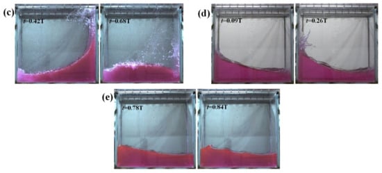
Figure 13.
Liquid movement in the liquid tank at 20% liquid-carrying rate from five cases of different excitation parameters: (a) A = 2°, f = 0.53 Hz; (b) A = 2°, f = 0.59 Hz; (c) A = 2°, f = 0.66 Hz; (d) A = 2°, f = 0.73 Hz; (e) A = 2°, f = 0.79 Hz (t is the motion time, T is the excitation period).
When the excitation frequency is increased to f = 0.59 Hz, the nonlinearity of the liquid intensifies, which is featured with the appearance of broken traveling waves and the hydraulic jumps near the tank wall. The liquid undergoes fragmentation and splashes, introducing perturbation to the two-dimensional sloshing. The three-dimensional effect starts to manifest, driven by the higher kinetic energy from the increased excitation frequency. This enables the liquid to reach the wall and climb further upwards.
When the excitation frequency rises to f = 0.66 Hz, the liquid impacts the tank top, forming a jet, and eventually causing the free liquid surface to overturn. The overturning sloshing wave breaks down and falls back, hitting the free liquid surface and creating a large number of air bubbles.
When the excitation frequency reaches f = 0.73 Hz, the sloshing wavefront is tumbled and broken at the bulkhead, and the phenomenon of roof impulse no longer occurs. When the excitation frequency further reaches f = 0.79 Hz, the sloshing wave surface is piled up at the bulkhead instead of climbing along the wall, and then the two traveling waves converge to form the hydraulic jumps.
By changing the excitation amplitude from 1° to 3° at the resonance frequency, the sloshing waveforms remain consistent, with variations only in the degree of nonlinear intensity. The generation of the hydraulic jumps under resonance conditions causes the liquid to hit the wall, and may involve flip and gas cavity phenomena [1]. By analyzing the flip mode of the liquid tank sloshing at resonance frequency, it is seen from Figure 14 that the flip mode (a) of breaking wave impact without air entrapment occurs for the two conditions of A = 1°, f = 0.66 Hz and A = 2°, f = 0.66 Hz. Meanwhile, for the condition of A = 3°, f = 0.66 Hz, the flip mode of (b) breaking wave impact with air entrapment is observed.
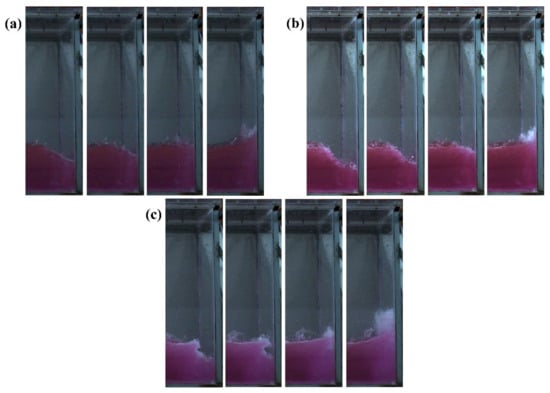
Figure 14.
Liquid turnover pattern in the liquid tank at a 20% liquid-carrying rate from three cases of different excitation parameters: (a) A = 1°, f = 0.66 Hz; (b) A = 2°, f = 0.66 Hz; (c) A = 3°, f = 0.66 Hz.
3.2.2. Sloshing at a Liquid Carrying Rate of 30%
In Figure 15, the liquid movement in the tank at a 30% liquid-carrying rate is examined. At the excitation frequency of 0.61 Hz, the free liquid surface presents standing wave characteristics. At f = 0.68 Hz, the free liquid surface transforms into an unbroken traveling wave.
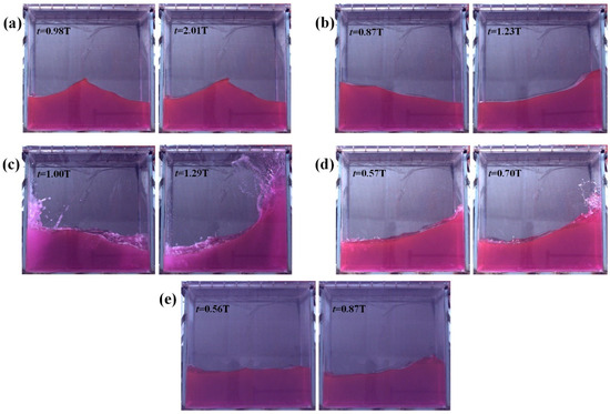
Figure 15.
Liquid movement in the liquid tank at a 30% liquid-carrying rate from five cases of different excitation parameters: (a) A = 2°, f = 0.61 Hz; (b) A = 2°, f = 0.68 Hz; (c) A = 2°, f = 0.76 Hz; (d) A = 2°, f = 0.84 Hz; (e) A = 2°, f = 0.91 Hz.
When the resonance frequency f = 0.76 Hz is reached, the liquid reaches the wall at a high speed, leading to a forceful impact. After the impact, the liquid continues to climb and the bubble stays in the impact area. This scenario is accompanied by a violent liquid fragmentation, marked by intense sloshing mixed with a large number of bubbles.
When the excitation frequency reaches f = 0.84 Hz, the waveform predominantly exhibits characteristics of fragmented traveling waves near the bulkhead. These waves continue to climb after reaching the wall surface before disintegration. However, compared to the resonance frequency, the extent of liquid surface breaking up is less severe, resulting in a reduction in sloshing intensity. Further elevating the excitation frequency to f = 0.91 Hz is characterized by a notable reduction in wave amplitude. The wavefront response mainly presents non-broken traveling waves, accompanied by small hydraulic jumps.
The flip mode of the liquid is incited by the relative motion of the wave peaks and troughs, causing accelerated liquid flow. This acceleration forces the troughs to rise rapidly at the wall, fostering a swift influx of liquid that subsequently leads to a vertical jet formation. As depicted in Figure 16, the two conditions A = 1°, f = 0.76 Hz and A = 2°, f = 0.76 Hz show the flip mode (a) of the breaking wave impact without air entrapment. In contrast, the A = 3°, f = 0.76 Hz condition demonstrates the flip mode (c) of the breaking wave impact with air-water mixing. These latter two flip modes occur less frequently during sloshing, as the breaking wave shock with air entrainment or air–water mixing requires a more violent liquid wavefront breakup and a higher degree of instability to be excited.
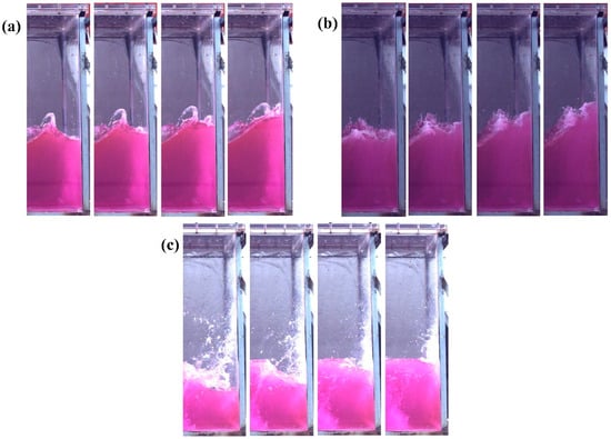
Figure 16.
Liquid turnover pattern in the liquid tank at a 30% liquid-carrying rate from three cases of different excitation parameters: (a) A = 1°, f = 0.76 Hz; (b) A = 2°, f = 0.76 Hz; (c) A = 3°, f = 0.76 Hz.
3.2.3. Sloshing at a Liquid Carrying Rate of 70%
Refer to Figure 17 for an examination of the liquid motion in the tank at a 70% carrying rate. At this rate and an excitation frequency f = 0.7 Hz, the liquid flows slowly in the tank in the form of a standing wave, accumulating along the tank wall as the tank itself moves.
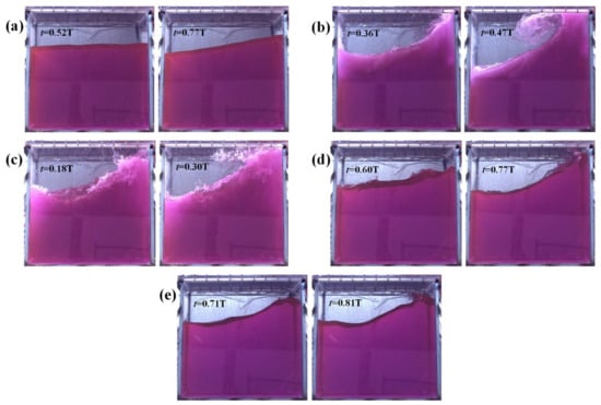
Figure 17.
Liquid movement in the tank at a 70% liquid-carrying rate from five cases of different excitation parameters: (a) A = 2°, f = 0.7 Hz; (b) A = 2°, f = 0.78 Hz; (c) A = 2°, f = 0.87 Hz; (d) A = 2°, f = 0.96 Hz; (e) A = 2°, f = 1.04 Hz.
When the excitation frequency reaches f = 0.78 Hz, the liquid hits the tank roof, producing a nearly horizontal free surface. This scenario results in frequent instances of liquid rushing to the roof with a violent jet being formed.
Upon reaching an excitation frequency of f = 0.87 Hz, the front and rear levels show a significant height difference, and a three-dimensional phenomenon featuring swirling-like waves occurs, which is due to the auto-parametric interactions between the main sloshing modes along the length and width of the tank [13]. This explains why the sloshing pressure at the free liquid level at the resonant frequency is smaller than the non-resonant frequency condition. When the liquid impacts the tank roof, it creates air cavities between the liquid and the tank’s sidewalls. Such roof impingement officially falls under the category of impact with an oscillatory air cavity. The presence of air cavities induces oscillations in the sloshing pressure and promotes the energy dissipation of the liquid flow.
At an excitation frequency of f = 0.96 Hz, the initial characteristics of sloshing wavefronts marked by hydraulic jumps come into view. A portion of the ascendant liquid surface contacts with the tank’s roof. The sloshing wave’s amplitude decreases, and topping no longer occurs.
The conditions conducive to topping depend on the liquid-carrying rate, with flat impact and impact with oscillating gas cavities being associated with finite liquid depth. In other words, these conditions do not necessitate a high liquid-carrying rate [1]. As shown in Figure 18, among the conditions where liquid topping occurs, the flat impact is observed for A = 1°, f = 0.87 Hz and A = 2°, f = 0.78 Hz, while impact with oscillating gas cavity arises for A = 2°, f = 0.87 Hz, A = 2°, f = 0.96 Hz, and A = 3°, f = 0.87 Hz. In the range of near-resonant frequency at the 70% liquid-carrying rate, the liquid roofing caused by smaller amplitude and lower frequency sloshing tends to be characterized by flat impact. In these cases, the water body climbs along the wall before impacting the tank roof. Conversely, larger amplitude and higher frequency sloshing entail greater kinetic energy, causing wave peaks to jump up and directly impact the tank’s roof, generating an impact with an oscillating gas cavity.

Figure 18.
Liquid topping in the tank at a 70% liquid-carrying rate from five cases of different excitation parameters: (a) A = 1°, f = 0.87 Hz; (b) A = 2°, f = 0.78 Hz; (c) A = 2°, f = 0.87 Hz; (d) A = 2°, f = 0.96 Hz; (e) A = 3°, f = 0.87 Hz.
3.3. Frequency Response of Sloshing Pressure
The sloshing experiences a transient phase when the forced pitch motion starts, and reaches a steady state after enough motion cycles due to the viscous damping effect [26]. In this section, the frequency response characteristics at both the transient phase and the steady state of the sloshing with different excitation amplitudes and frequencies are investigated.
To perform the frequency response analysis, two segments of the time history curve of the sloshing pressure from the measurement point at the free liquid surface level are shown in Figure 19. The first segment, which is from 10 s to 40 s, is a representative segment of the transient phase, while the second segment lasting from 370 s to 400 s stands for the steady state. Spectral analysis based on the Fast Fourier analysis (FFT) is applied to each segment to obtain the power spectrum for each condition.

Figure 19.
Time-course curves of sloshing pressures at h = 20%H, A = 2°, f = 0.53 Hz condition: (a) the initial phase (10–40 s); (b) the final phase (370–400 s).
In Figure 20, power spectra are presented with different excitation amplitudes (1°, 2°, and 3°) arranged horizontally and various excitation frequencies (0.8 f1, f1, and 1.2 f1) listed vertically for comparative analysis. Examining the power spectra depicted in Figure 20a–c, it is seen that these power spectra predominantly contain the frequency component fe and its octaves. fe emerges as the dominant response frequency while the octaves exhibit relatively lower energy levels. As the excitation frequency transitions from the non-resonant to the resonant frequency, there is a noticeable rise in the energy peak, accompanied by an augmented distribution of energy at higher frequencies. Specifically, at the resonant frequency, the power spectrum reveals pronounced peaks corresponding to response frequencies: f1, 2 f1, 3 f1, and 4 f1, successively. In Figure 20b–e, it becomes apparent that at the resonant frequency, energy peaks linked to fe and its multiples escalate in correspondence with increased excitation amplitudes. Observing the power spectra in Figure 20, it is evident that energy dissipation occurs in the liquid tank from the initial phase (10–40 s) to the final phase (370–400 s) of the sloshing. This dissipation manifests as diminishing peak values for the excitation frequency fe and its octave responses, indicating the gradual dissipation of unsteady perturbations caused by transient effects through the viscous action within the liquid.
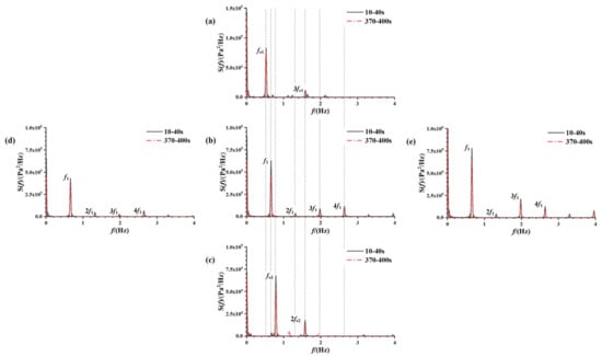
Figure 20.
Power spectra of the sloshing pressure history curve for the measurement point at the free liquid level at a 20% liquid-carrying rate from five cases of different excitation parameters: (a) A = 2°, f = 0.53 Hz; (b) A = 2°, f = 0.66 Hz; (c) A = 2°, f = 0.79 Hz; (d) A = 1°, f = 0.66 Hz; (e) A = 3°, f = 0.66 Hz.
The power spectra depicted in Figure 21a–c reveal a distinct secondary peak at the condition f = 0.61 Hz, attributable to the proximity between the excitation frequency’s multiple (2 fe1 = f2 = 1.22 Hz) and any of the resonance frequencies, indicating secondary resonance phenomena. At the f = 0.91 Hz condition, the energy peak associated with the frequency component f1 emerges in the initial phase, attributed to transient disturbances, dissipating by the final phase due to viscous damping effects within the liquid. However, at the resonant frequency, the impact of viscous damping is less pronounced. The synchronization between the excitation frequency and the intrinsic frequency accelerates the liquid tank’s resonance state, sustaining continuous excitation and limiting energy dissipation. In Figure 21b–e, a noticeable increase in peak energy value is observed at the resonance frequency with an increase in excitation amplitude from 1° to 2°. Larger amplitudes lead to more pronounced octave response peaks in the power spectrum. Subsequent to an increase from 2° to 3° in excitation amplitude, a relative reduction in the peak f1 response is observed along with an increase in the octave response peak. This heightened nonlinearity amplifies higher-order sloshing modes, manifesting more discernible higher harmonics.
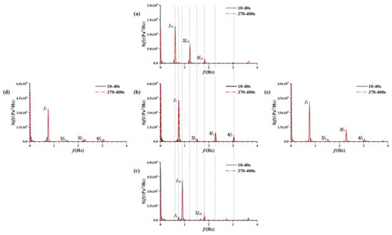
Figure 21.
Power spectra of the sloshing pressure history curve for the measurement point at a 30% liquid-carrying rate free liquid surface from five cases of different excitation parameters: (a) A = 2°, f = 0.61 Hz; (b) A = 2°, f = 0.76 Hz; (c) A = 2°, f = 0.91 Hz; (d) A = 1°, f = 0.76 Hz; (e) A = 3°, f = 0.76 Hz.
In Figure 22a–c, noticeable energy dissipation is evident over time at non-resonant frequencies within the liquid tank. Contrarily, at the resonant frequency, there is a lack of significant decay in peak energy over time. Analyzing Figure 22b–e power spectra further reveals that an increase in excitation amplitude from 2° to 3° significantly reduces the dominant f1 response peak while relatively enhancing the octave response peak. This phenomenon is attributed to the emergence of a three-dimensional effect generating vortex waves and more conspicuous higher harmonic energy. This highlights the excitation amplitude’s role as a destabilizing factor influencing the three-dimensional nature of the sloshing process [27].
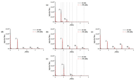
Figure 22.
Power spectra of the sloshing pressure history curve for the measurement point at the free liquid level at a 70% liquid-carrying rate from five cases of different excitation parameters: (a) A = 2°, f = 0.70 Hz; (b) A = 2°, f = 0.87 Hz; (c) A = 2°, f = 1.04 Hz; (d) A = 1°, f = 0.87 Hz; (e) A = 3°, f = 0.87 Hz.
4. Conclusions
In this paper, a series of rectangular liquid tank sloshing tests under different parameter controls are carried out. The effects of excitation frequency and excitation amplitude on the sloshing characteristics under simple harmonic excitation are investigated through statistical analysis of impact pressures, image analysis, and frequency domain analysis, and the nonlinear behaviors of the tank sloshing under different liquid-carrying rates are explored. The following conclusions are drawn from the experimental study:
(1) Across three liquid-carrying rates, a 20% liquid-carrying rate demonstrates the most violent sloshing process and the highest impact pressure. Approaching the resonance frequency induces resonant sloshing within the liquid tank while the sloshing pressure increases as the excitation amplitude increases. However, at a 70% liquid-carrying rate, the maximum sloshing pressure occurs at 0.9 f1, which indicates that the sloshing nonlinearity leads to the resonance frequency shift, indicating a “soft spring” characteristic of sloshing.
(2) Four waveform variations are observed, including standing waves, unbroken traveling waves, broken traveling waves, and hydraulic jumps, with the occurrence of each type related to the excitation frequency. The three-dimensional swirling wave effect is presented at a liquid-carrying rate of 70% under resonant frequency excitation. For the flipping modes, the breaking wave impact without air entrapment is the most observed mode during the resonant sloshing, while the occurrence of the other two flipping modes—the breaking wave impact with air entrapment and the breaking wave impact with air–water mixing—requires a more unstable sloshing excitation. Liquid topping phenomena also relate to the liquid-carrying rate, with only flat and oscillating air-cavity impact occurring in the sloshing tests at a 70% liquid-carrying rate.
(3) Power spectra show dominant response frequencies aligned with excitation frequencies and their multiples. Resonant frequency showcases negligible energy dissipation in the liquid tank. Amplifying excitation amplitude highlights higher harmonic energy in the spectrum. At non-resonant frequencies, sloshing pressure frequency responses evolve regularly from transient to steady state, with primary energy dissipation observed in decreased excitation frequency and its octave response peak.
Author Contributions
Conceptualization, K.L.; methodology, P.P.; resources, Z.Z.; writing—original draft preparation, X.L.; writing—review and editing, Z.G.; supervision, K.L.; funding acquisition, K.L. All authors have read and agreed to the published version of the manuscript.
Funding
This research was funded by [National Natural Science Foundation of China] grant number [52171311, 52271279].
Data Availability Statement
Data are contained within the article.
Acknowledgments
The author sincerely thanks the School of Naval Architecture and Ocean Engineering, Jiangsu University of Science and Technology, for providing experimental setup and other instrumental facilities.
Conflicts of Interest
The authors declare no conflict of interest.
References
- Faltinsen, O.M.; Timokha, A.N. Sloshing; Cambridge University Press: Cambridge, UK, 2009. [Google Scholar]
- Faltinsen, O.M.; Rognebakke, O.F.; Timokha, A.N. Transient and steady-state amplitudes of resonant three-dimensional sloshing in a square base tank with a finite fluid depth. Phys. Fluids 2006, 18, 012103. [Google Scholar] [CrossRef]
- Wei, Z.J.; Yue, Q.J.; Ruan, S.L. An experimental investigation of liquid sloshing impact pressure in a rectangular tank. In Proceedings of the ISOPE International Ocean and Polar Engineering Conference, Rhodes, Greece, 17–22 June 2012; Volume I, p. ISOPE-I-12-534. [Google Scholar]
- Jiang, M.; Ren, B.; Wang, G.; Wang, Y. Laboratory investigation of the hydroelastic effect on liquid sloshing in rectangular tanks. J. Hydrodyn. 2014, 26, 751–761. [Google Scholar] [CrossRef]
- Bulian, G.; Botia-Vera, E.; Souto-Iglesias, A. Experimental sloshing pressure impacts in ensemble domain: Transient and stationary statistical characteristics. Phys. Fluids 2014, 26, 032102. [Google Scholar] [CrossRef]
- Delorme, L. Sloshing Flows: Experimental Investigation and Numerical Simulations with Smoothed Particle Hydrodynamics. Ph.D. Thesis, Universidad Politécnica de Madrid, Madrid, Spain, 2008. [Google Scholar]
- Saltari, F.; Pizzoli, M.; Coppotelli, G.; Gambioli, F.; Cooper, J.E.; Mastroddi, F. Experimental characterisation of sloshing tank dissipative behaviour in vertical harmonic excitation. J. Fluid. Struct. 2022, 109, 103478. [Google Scholar] [CrossRef]
- Qiu, Y.; Bai, M.; Liu, Y.; Lei, G.; Liu, Z. Effect of liquid filling level on sloshing hydrodynamic characteristic under the first natural frequency. J. Energy Storage 2022, 55, 105452. [Google Scholar] [CrossRef]
- Lin, X.; Xu, L.; Liu, Y.C.; Fan, C.M. An efficient localized Trefftz method for the simulation of two-dimensional sloshing behaviors. Ocean Eng. 2024, 299, 117414. [Google Scholar] [CrossRef]
- Bardazzi, A.; Lugni, C.; Faltinsen, O.M.; Durante, D.; Colagrossi, A. Different scenarios in sloshing flows near the critical filling depth. J. Fluid. Mech. 2024, 984, A73. [Google Scholar] [CrossRef]
- Luo, M.; Wang, X.; Jin, X.; Yan, B. Three-dimensional sloshing in a scaled membrane LNG tank under combined roll and pitch excitations. Ocean Eng. 2020, 211, 107578. [Google Scholar] [CrossRef]
- Olsen, H.A.; Johnsen, K. Nonlinear Sloshing in Rectangular Tank: A Pilot Study on the Applicability of Analytical Models; Report 74-72-S; Det Norske Veritas: Hovik, Norway, 1975; Volume 2. [Google Scholar]
- Gurusamy, S.; Kumar, D. Experimental study on nonlinear sloshing frequency in shallow water tanks under the effects of excitation amplitude and dispersion parameter. Ocean Eng. 2020, 213, 107761. [Google Scholar] [CrossRef]
- Ibrahim, R.A. Assessment of breaking waves and liquid sloshing impact. Nonlinear Dynam. 2020, 100, 1837–1925. [Google Scholar] [CrossRef]
- Liu, G.; Lin, Y.; Guan, G.; Yu, Y. A numerical technique for sloshing in an independent type C LNG tank with experimental investigation and validation. Int. Shipbuild Prog. 2017, 64, 79–100. [Google Scholar] [CrossRef]
- KIM, H.I.; Kwon, S.H.; Park, J.S.; Lee, K.H.; Jeon, S.S.; Jung, J.H.; Ryu, M.C.; Hwang, Y.S. An experimental investigation of hydrodynamic impact on 2-D LNGC models. In Proceedings of the ISOPE International Ocean and Polar Engineering Conference, Osaka, Japan, 21–26 July 2009; Volume I, p. ISOPE-I-09-539. [Google Scholar]
- Bunnik, T.; Huijsmans, R. Large scale LNG sloshing model tests. In Proceedings of the ISOPE International Ocean and Polar Engineering Conference, Lisbon, Portugal, 1–6 July 2007; Volume I, p. ISOPE-I-07-338. [Google Scholar]
- Luo, D.; Liu, C.; Sun, J.; Cui, L.; Wang, Z. Sloshing effect analysis of liquid storage tank under seismic excitation. Structures 2022, 43, 40–58. [Google Scholar] [CrossRef]
- Zhao, W.; Yang, J.; Hu, Z. Effects of sloshing on the global motion responses of FLNG. Ships Offshore Struct. 2013, 8, 111–122. [Google Scholar] [CrossRef]
- Faltinsen, O.M. A Nonlinear Theory of Sloshing in Rectangular Tanks. J. Ship Res. 1974, 18, 224–241. [Google Scholar] [CrossRef]
- Ibrahim, R.A.; Pilipchuk, V.N.; Ikeda, T. Recent Advances in Liquid Sloshing Dynamics. Appl. Mech. Rev. 2001, 54, 133–199. [Google Scholar] [CrossRef]
- Chen, Y.; Xue, M.A. Numerical Simulation of Liquid Sloshing with Different Filling Levels Using OpenFOAM and Experimental Validation. Water 2018, 10, 1752. [Google Scholar] [CrossRef]
- Faltinsen, O.M. Sloshing. Adv. Mech. 2017, 47, 1–24. [Google Scholar]
- Lugni, C.; Brocchini, M.; Faltinsen, O.M. Wave impact pressures: The role of the flip-through. Phys. Fluids 2006, 18, 122101. [Google Scholar] [CrossRef]
- Faltinsen, O.M. Hydrodynamics of High-Speed Marine Vehicles; Cambridge University Press: Cambridge, UK, 2005. [Google Scholar]
- Jin, X.; Tang, J.; Tang, X.; Mi, S.; Wu, J.; Liu, M.; Huang, Z. Effect of viscosity on sloshing in a rectangular tank with intermediate liquid depth. Exp. Therm. Fluid Sci. 2020, 118, 110148. [Google Scholar] [CrossRef]
- Zhang, C.; Ning, D.; Teng, B. Secondary resonance of liquid sloshing in square-base tanks undergoing the circular orbit motion. Eur. J. Mech. B-Fluid. 2018, 72, 235–250. [Google Scholar] [CrossRef]
Disclaimer/Publisher’s Note: The statements, opinions and data contained in all publications are solely those of the individual author(s) and contributor(s) and not of MDPI and/or the editor(s). MDPI and/or the editor(s) disclaim responsibility for any injury to people or property resulting from any ideas, methods, instructions or products referred to in the content. |
© 2024 by the authors. Licensee MDPI, Basel, Switzerland. This article is an open access article distributed under the terms and conditions of the Creative Commons Attribution (CC BY) license (https://creativecommons.org/licenses/by/4.0/).