1. Introduction
Laminar and turbulent conditions are the main types of water flow, characterizing both anthropogenic and natural environments or systems (e.g., pipelines, rivers, and groundwater).
When the flow is turbulent and the velocity decreases, a progressive change to laminar flow can occur, and vice versa. This change depends on the hydraulic and geometric characteristics of the liquid and the medium, respectively, and has important consequences on the hydraulic pressure and the flow velocity.
The Darcy–Weisbach equation is the most commonly used hydraulic law to model the water flow under turbulent conditions. Julius Ludwig Weisbach (a German mathematician and engineer) [
1], Henry Darcy (a French hydraulic engineer) [
2], and others developed this equation for the calculation of hydraulic head losses,
h, due to pipe friction [
3]. In a straight tube with inner diameter
d and length
L, the flow velocity,
v, is related to the pressure lost, Δ
P, by the following formula:
where
f is a dimensionless parameter known as the Darcy friction factor, which depends on the geometric and hydraulic features of the flow, described in the next sections;
ρ is the density of the water.
Under laminar flow conditions, the Poiseuille law describes the relation between the flow velocity in small conduits and the hydraulic head losses [
4]. This law comes from the French physiologist–physicist Jean Leonard Marie Poiseuille [
4]. During the 1880s, Hagen [
5] reached similar results to those of Poiseuille on the water flow in cylindrical tubes; for this reason, the Poiseuille law is also known as the Poiseuille–Hagen law. In their review of the Poiseuille law, Sutera and Skalak [
5] stated that the results of Hagen were less extensive and less accurate than Poiseuille’s.
The general form of the Poiseuille law expresses the velocity of a liquid,
v, in a tube with constant diameter,
d, and length,
L, in relation to the difference in the liquid pressure between the ends of the tube, Δ
P:
where
μ is the dynamic viscosity of the liquid.
Equation (2), which was found empirically, can be derived from physically based assumptions [
6,
7].
The flow type (turbulent or laminar) can be verified by the Reynolds number,
Re:
where
ρ is the density of the fluid. The Reynolds number is more formally defined as the ratio of inertial to viscous stresses. Thus, when the inertial stresses become too large, the viscosity will be unable to suppress eddies, and turbulence develops because the resulting vortical motion is underdamped. It is particularly important to focus on the lower limit of turbulent flow, defined by the lower critical Reynolds number,
Re(crit), when all the turbulences entering the flow from any source will eventually be damped out by viscosity. This lower critical Reynolds number thus sets a limit below which laminar flow will always occur [
7].
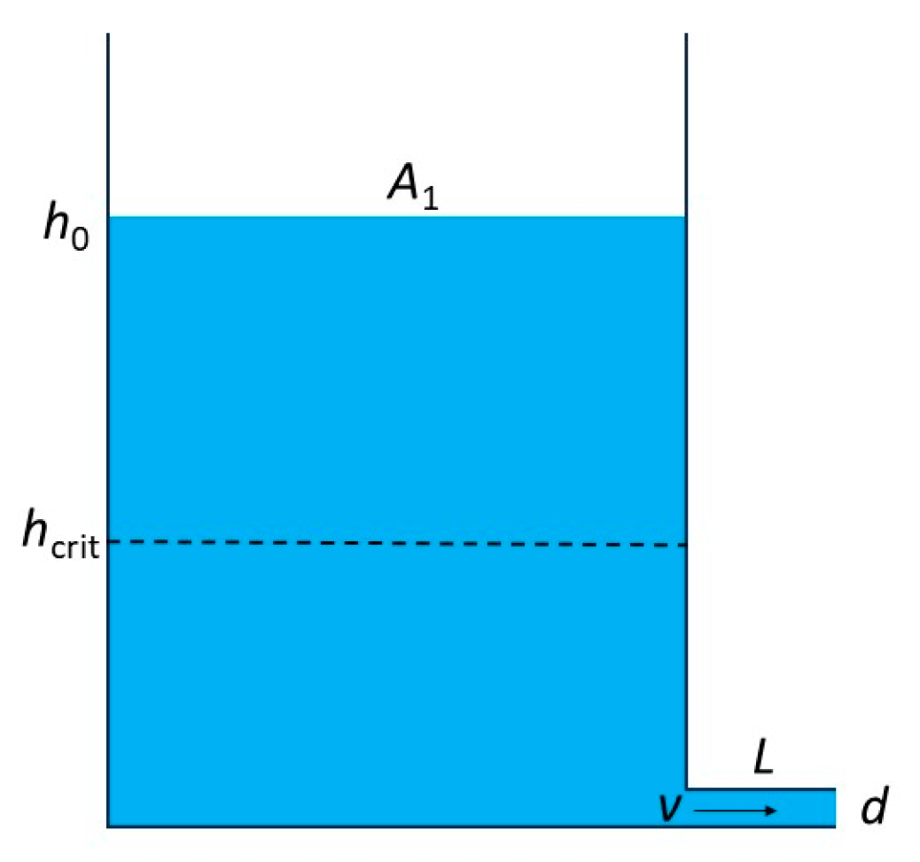
To investigate the transition between turbulent and laminar flows, a simple tank reservoir with a basal area
A1 (
Figure 1) is used as a model to test different hydraulic laws. The reservoir is drained by a hole through a tank tube with a length
L and diameter
d (with an area
A2), allowing the control of the hydraulic conditions and simulation of output velocity.
During the drainage, the change from turbulent to laminar flow in the tank tube has to occur in correspondence with a specific water height hcrit, which depends on the geometrical features of the tank tube (L, d, f), and the hydraulic proprieties of the liquid as well.
We will focus on some hydraulic aspects concerning the transition from the turbulent to the laminar flow by employing analytical tools to simulate the drainage of the tank reservoir in
Figure 1.
In natural media, such as aquifers, water flow is laminar in minor fractures and the pore matrix. On the other hand, in wider voids such as karst conduits, the water flow can be turbulent. The hydraulic condition of groundwater flow can switch from turbulent to laminar and vice versa due to the function of the flow velocity and the geometry of the medium, which vary in space and time, especially in karst aquifers. For example, the turbulent-to-laminar transition during flow recession is a well-known hydraulic phenomenon observed in karst spring hydrographs [
8], but it is not easy to identify in time and space [
9].
2. Tank Reservoir Models
For the tank reservoir shown in
Figure 1, the drainage can be described using a specific theoretical hydraulic law, and the discharge–time plots can be found starting from an initial water height in the reservoir,
h0, at time
t0 = 0, applying the principle of mass and volume conservation [
10]. The water pressure in the tank tube is directly controlled by the water height when drainage starts (
t0), assuming a zero gauge pressure at the end of the tube.
2.1. Torricelli Reserovir
The simplest physical conditions occur when the friction forces and viscosity of the flow can be neglected during the drainage; these conditions approximately occur when the tube’s diameter is wide, its walls are smooth, and the velocity is limited. Under such simplifications, the velocity of the flow in the tube is expressed in terms of
Torricelli efflux velocity:
where
g is the gravitational acceleration, and
h is the height of the water above the tube. In this case, the velocity is independent of the tank-tube length,
L.
Considering that the section area of the tank tube is
A2 = (π/4)
d2, the discharge from the outlet,
Q, is as follows:
As the discharged water volume must equal the water storage variation in the tank reservoir, the following equation is obtained [
10]:
Combing Equations (5) and (6), the general equation describing the drainage at time
t is as follows [
10]:
with constants:
For the Torricelli reservoir, the parameter
αT has dimensions [L
3·T
–2] and expresses the linear decrease in discharge with time; the main consequence of this behavior is the constant slope of the discharge–time plot at any time, which is independent of the initial height
h0 [
10]. It is proportional to the second power of the hole cross-section
A2, and it is inversely proportional to the base area,
A1, of the tank reservoir.
The drainage of the reservoir described by using the Torricelli efflux velocity is a theoretical condition based on the assumption that no energy losses occur during drainage; however, it is a useful reference when comparing different hydraulic laws, which considers the role of friction forces taking place within the liquid (viscosity) or at the flow–tube interface.
2.2. Darcy–Weisbach Reserovir
If turbulent flow occurs in the tank tube, Equation (1) can be used to model the drainage. If the gauge pressure is zero at the end of the tank tube, the term Δ
P can be replaced by
ρ⋅
g⋅
h, and the outflow discharge,
Q, from the tank tube with section area
A2 is as follows:
Equation (9) is also known Thrailkill equation [
11].
Comparing Equations (5) and (9), the following condition has to occur:
as the Torricelli efflux velocity is the theoretical maximum possible.
The friction factor,
f, is a non-constant parameter that depends on the Reynolds number,
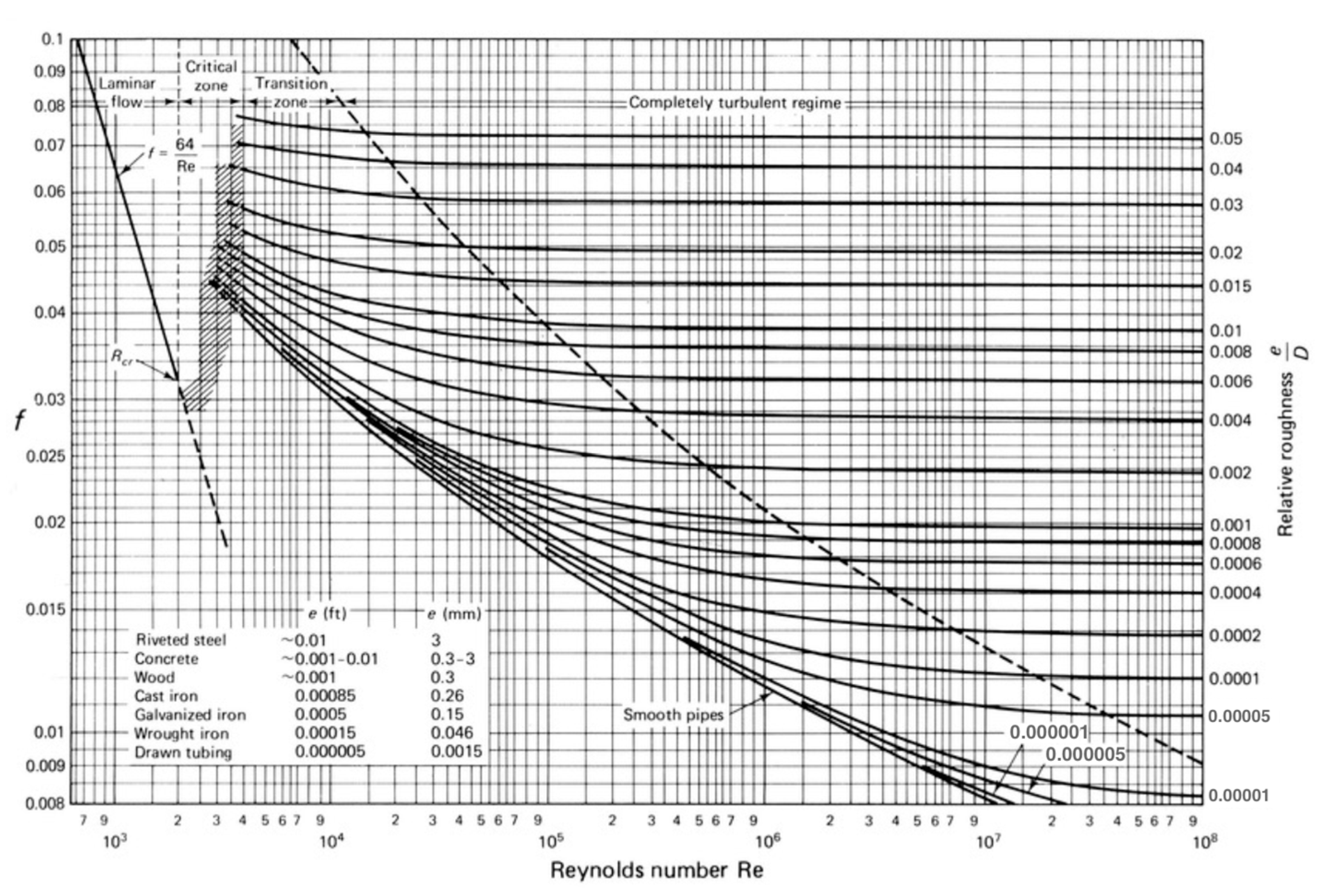
Re, as shown in the well-known Moody diagram [
12] of
Figure 2, for different ratios between the average height of the roughness protuberances,
ε, and diameter of the tube,
d. Furthermore, the Darcy friction factor,
f, depends on the flow velocity; this means that the velocity,
v, in Equation (1) is present also on its right side and causes the well-known complex relationship with the hydraulic head,
h. As a consequence of this complication, the discharge–time relationship of turbulent flow can be found by an iterative process [
13], and no equation can be found describing the relation between discharge and time.
Based on the flow regime, four zones are identified in the Moody diagram:
- (i)
Completely turbulent zone
- (ii)
Transition zone
- (iii)
Critical zone
- (iv)
Laminar flow zone
The completely turbulent regime is described on the right side of the Moody diagram, and occurs for a high value of Re (and thus, of the flow velocity), where each straight line refers to a specific value of the ε/d ratio. The complete turbulence rapidly develops for high values of ε/d, whereas it needs very high Re values for smooth conduits. Under the completely turbulent flow regime, the friction factor, f, does not depend on the Reynolds number, Re, nor on the flow velocity.
The
transition zone (
Figure 2) defines a region between the completely turbulent (right part) and the laminar flow conditions (left part). This means that a moving fluid under this transient hydraulic stage contains a laminar component; the amount of this component progressively increases toward the left and causes a progressive increase in the friction factor,
f, up to the
critical zone. For high values of
ε/
d (and of
f), the width of the
transition zone decreases.
Natural tubes in aquifers have much higher friction factors than straight manufactured pipes because the walls are not smooth and the channels are not straight [
14]. There are very few studies in this field, and most of them refer to the results by Jeannin [
15]. These studies assume very high values of the friction factor, ranging between 0.1 and 340 for karst conduits [
16], which lie outside the Moody diagram. With these high values, the friction factor of natural channels in aquifers could be considered almost independent of the Reynolds number,
Re. This characteristic causes an abrupt transition from completely turbulent to laminar flow conditions in natural conduits, almost without the
transition zone. In the interval values
f = 0.1 ÷ 340, Equation (10) becomes the following:
which is always respected in natural karst conduits, as
L >>
d.
For the Darcy–Weisbach reservoir, assuming the friction factor
f to be independent of
Re in natural conduits, Equations (6)–(8) become the following:
with constants:
Under the assumption of a constant friction factor, the Darcy–Weisbach reservoir also would provide a linear decrease in the discharge with time.
However, unlike the Torricelli law, the drainage of the Darcy–Weisbach reservoir involves an energy loss; the amount of energy lost is inversely proportional to the factor .
During the drainage, before reaching the laminar flow zone, there is an uncertain zone known as the critical zone where an abrupt decrease in the friction factor value, f, occurs, and no relationship between f and Re exists, approximately in range 2000 < Re < 3000. The lines of the transition zone could be extended towards the left, up to Re = 2000, but these modifications do not solve the disconnection of these lines with the laminar flow zone on the left. The hydraulic behavior of the flow in the critical zone and laminar flow zone will be discussed in the next section.
2.3. Poiseuille Reservoir
Under laminar conditions in the tank tube, the flow velocity is described by Equation (2). If the gauge pressure is zero at the end of the tank tube, the term Δ
P can be replaced by
ρ⋅
g⋅
h, and the discharge,
Q, is as follows:
Given that the discharged water volume must equal the variation in the tank-reservoir water storage, the following equation is obtained [
11]:
Combining Equations (15) and (16), the general formula describing the drainage at time
t for the Poiseuille reservoir is as follows [
11]:
with constants:
The parameter α
P has the dimension [T
−1] and expresses the drainage characteristics of the Poiseuille reservoir. Equation (16) represents Maillet’s formula [
17], and the constant α
P is known as the recession coefficient, which controls the exponential decay of the discharge with time.
In the Moody diagram, the laminar condition is associated with a single straight line (independently from the different
ε/
d values), which represents the Darcy friction factor for low values of the Reynolds number. For straight manufactured pipes, laminar conditions occur when
Re < 2000 (
Figure 2), and the following relationship occurs:
Equation (19) has been known since the early 1900s but it is unknown who first introduced it [
3]; it will be discussed in the next sections. Replacing the friction factor,
f, in Equation (1) (Darcy–Weisbach equation) the Poiseuille law (Equation (2)) is found. In laminar conditions, the friction factor is physically explained by a combination of other hydraulic factors, and it is inversely proportional to the velocity of the flow (
f = 64
μ/
ρvd).
The drainage process of the tank reservoir (
Figure 1) predicted by the Poiseuille law has been compared to that predicted by Darcy’s law, filling the tank tube with sand having hydraulic conductivity
K [
18].
3. From Turbulent to Laminar Flow
The fixed geometric and hydraulic conditions of the tank reservoir of
Figure 1 allow the use of Darcy–Weisbach and Poiseuille laws when gravity drainage occurs. To reduce the complexity of the analytical solutions, a constant friction factor,
f, is considered during the drainage, which is an acceptable assumption for the values of
ε/
d > 0.015.
The small diameters or great lengths of the tank tube favor the conditions imposed by Equation (10); whereas, the wide diameters or short lengths of the tank tube favor the tendency of f ≈ d/L, and turbulent conditions decrease due to a decrease in the friction forces. The latter theoretically became null under Torricelli efflux conditions. However, when the factor d/fL < 1, the drainage is slower than drainage from a Torricelli reservoir, and the initial discharge, Q0, is lower as well.
Fixing the Reynolds number at its critical lower value,
Re =
Re(crit), the condition for the laminar flow occurs when the flow velocity is
v <
vcrit, with
vcrit:
Combining Equations (20) and (2), the critical hydraulic gradient can be found as follows:
where
hP(crit) is the critical height in the reservoir, below which laminar flow occurs following the Poiseuille law under the hydraulic gradient
i <
iP(crit) in the tube with length
L.
If the same value
Re(crit) is considered for the turbulent flow (that is, the flow is turbulent for
Re > Re(crit)), combining Equations (1) and (20), the critical height above which turbulent flow occurs,
hDW(crit), is obtained as follows:
with the critical hydraulic gradient
iDW(crit) in the tube with length
L.
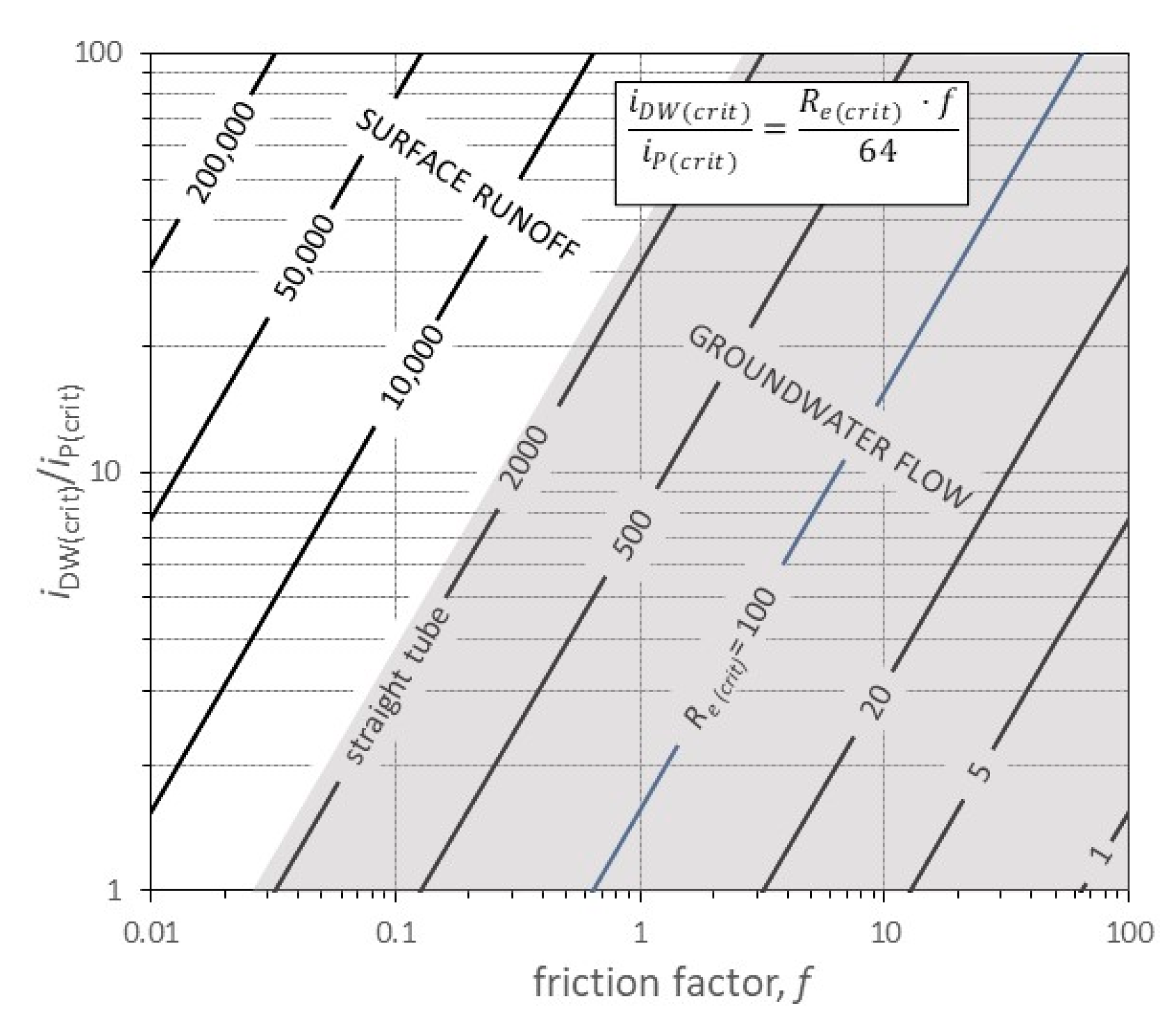
The ratio between Equations (21) and (22) provides the following:
If
hDW(crit) =
hP(crit), Equation (23) becomes Equation (19) for
Re ≤
Re(crit), and for
Re(crit) = 2000, the friction factor is
f = 0.032. This stage corresponds to the extreme lower point of the line describing the laminar flow in the Moody diagram (
Figure 2). However, for any curve describing the turbulent flow in the Moody diagram, the friction factor is
f > 0.032 for
Re(crit) = 2000. Therefore:
Equation (24) is an obvious energetic condition, as laminar flow is more efficient than turbulent flow. Equation (24) explains the presence of the abrupt decrease in the friction factor, f, in the critical zone, where both models (Darcy–Weisbach and Poiseuille laws) fail to describe the flow velocity.
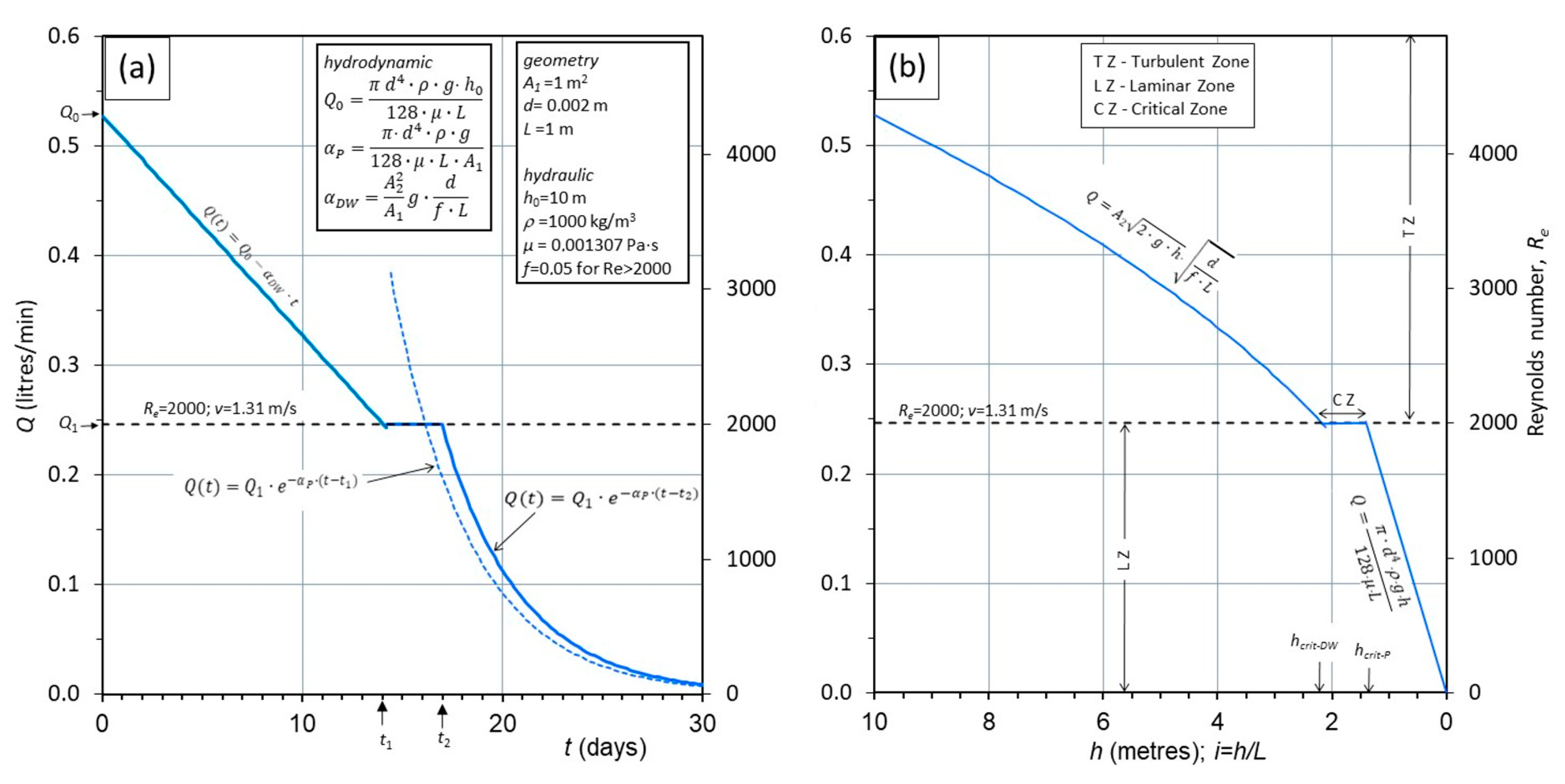
The effect of this behavior can be seen by simulating the drainage of the tank reservoir in
Figure 1, which is described by the discharge and water height–time plots in
Figure 3. The initial water height is
h0 = 10 m, the tank-tube diameter
d = 2 mm, and friction factor
f = 0.05. It has been assumed that the turbulent regime occurs up to
Re(crit) = 2000 without the
transition zone, which can be neglected for a high value of the friction factor,
f, as previously discussed. As
L = 1, the
x-axis in
Figure 3b also provides the values of the hydraulic gradient,
i, in the tube.
Initially, the drainage occurs under turbulent flow and provides a linear discharge decrease with time up to a value
Q1 = 0.245 L/min (
v = 1.31 m/s), corresponding to a water height
h =
hDW(crit) = 2.18 m, where the Reynolds number reaches its critical value
Re(crit) = 2000. At this stage (
t1 ≈ 14 days), the laminar flow cannot begin, as it would provide a discharge higher than 0.245 L/min (dashed line). Thus, from this time the discharge has to be constant until a water height
h =
hP(crit) = 1.39 m is reached in the reservoir (from
t1 ≈ 14 to
t2 ≈ 17 days); during this time interval, the flow progressively changes from turbulent to laminar. This reorganization of the flow allows for a reduction in the energy lost during the drainage, as the same discharge (or velocity) in the tube,
Q1 = 0.245 L/min, requires different hydraulic heads to reach laminar condition (
hP(crit) = 1.39 m). The flow velocity (
v = 1.31 m/s) is constant during the transition flow regime, despite the water height decreases (hydraulic gradient in the tube as well, from
iDW(crit) = 2.18 to
iP(crit) = 1.39). The relationship between
Q and
h is shown in
Figure 3b; between
hDW(crit) =2.18 m and
hP(crit) = 1.39, the discharge assumes the same value, and a flow transition occurs. This phase corresponds to the
critical zone, and no physical or empirical laws are available to describe this transition.
The critical zone also corresponds to the discontinuity of the friction factor value,
f. In the example (
Figure 3),
f changes from 0.05 to 0.032 in the
critical zone, but this discontinuity comes from the need for Equation (1) for
Re >
Re(crit) and Equation (2) for
Re <
Re(crit). However, the use of the friction factor during the laminar flow is superfluous, as it is explained by the combination of other hydraulic factors.
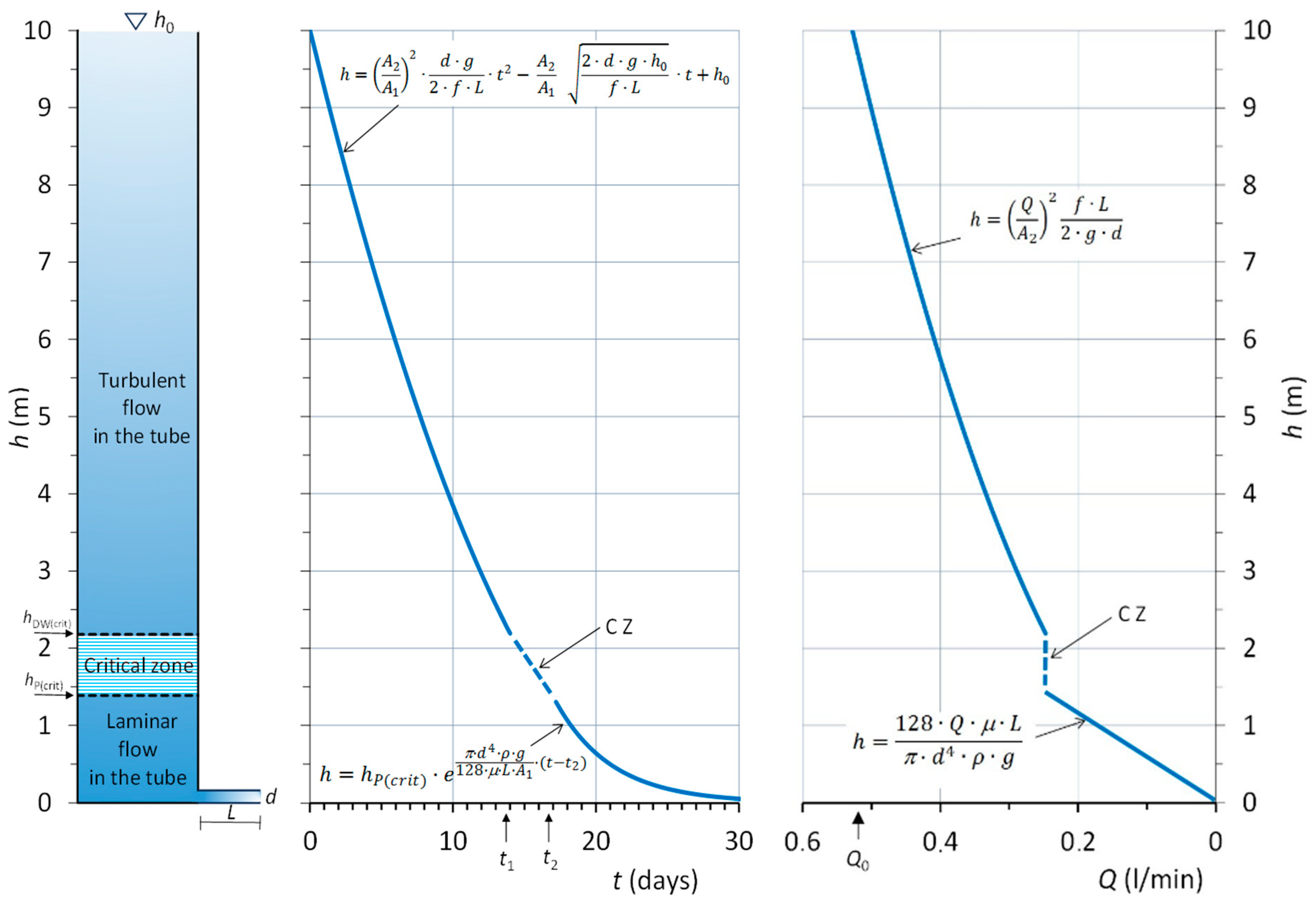
Figure 4 highlights the main stages discussed in
Figure 3, and shows the relationships of the water level with time,
h =
f(
t), and discharge,
h =
f(
Q). In the
critical zone, no equation is available to describe the flow.
4. Discussion
While the laminar flow can be described by physically based laws, such as the Poiseuille law, the turbulent flow is a complex water motion described using empirical equations. In the Darcy–Weisbach equation, the friction factor depends on the velocity of the flow, and thus, it can be solved only by iterations. This circumstance occurs in the transition zone of the Moody chart, where the friction factor, f, varies between the completely turbulent regime and laminar flow zones. The variation in f in the transition zone was a mathematical necessity to extend the curves of the Moody diagram towards the lowest possible flow velocity by Equation (1) before reaching the critical zone. In fact, in the transition zone the flow contains a laminar component inside the turbulent regime and requires a “correction” of the parameter f (Equation (1)) during the drainage. This is only a convenient solution to extend the relationship between f and Re in the transition zone, but it has complicated the Darcy–Weisbach equation which needs to be solved by iteration. The friction factor has a constant value only in the completely turbulent regime zone, even if the Darcy–Weisbach formula always remains an empirical relationship.
To simplify the analytical description of the reservoir drainage under turbulent flow conditions, the friction factor has been assumed constant; this circumstance occurs for very rough tubes, and cannot be assumed for smoothed tubes. Under such an assumption, the analytical solution provides a linear discharge decrease with time (
Figure 3a).
The solution obtained by the Poiseuille law provides an exponential discharge decrease with time. The Poiseuille law can be used only for the velocity of the flow v < vcrit (or Re < Re(crit)), and it is valid only for small diameters of the tank tube, as the velocity (and thus Re) depends on the square of the diameter.
In the field of hydrogeology, these results are in line with the observed shapes of the spring hydrographs from many karst aquifers. In karst spring hydrographs, the initial part of the recession is linear and often interpreted as turbulent flow [
8] or non-Darcian flow [
9], which evolves to an exponential form, typical of a Darcian (laminar) flow. However, the turbulent-to-laminar flow transition in natural environments (rivers, springs, and groundwater) varies in time and space due to the strong heterogeneity of the natural media. Therefore, the effects of this behavior tend to smooth the hydrographs.
This is a reason why in actual aquifers, under transient flow conditions in a fissure, the flow can change its hydraulic regime. Because these conditions do not occur simultaneously in a fissured aquifer, the discontinuity observed in the hydrograph of
Figure 3 is always more or less smoothed.
The use of the reservoir in
Figure 1 simplifies many aspects of this complex topic and allows us to focus on the hydraulic behavior of the flow. In particular, the discontinuity observed from turbulent to laminar flow is a consequence of different frictional forces taken into account by the different hydraulic laws. This discontinuity depends on the hydraulic gradient ratio
iDW(crit)/
iP(crit), and this ratio increases for rough paths or conduits and decreases for smooth paths or conduits. Considering Equation (23), for a fixed value of
Re(crit), the ratio
hDW(crit)/
hP(crit) (or
iDW(crit)/
iP(crit)) increases with
f, that is, it increases with the surface roughness of the tube; moreover, a low value of
Re(crit) requires high values of
f according to the very rough path of the water flow inside the void of the soil or through rock fractures and karst conduits.
Figure 5 highlights the field of groundwater flow in the saturated zone of aquifers (high values of
f and low values of
Re(crit)).
In granular aquifers, the critical Reynolds number is very low and could be also less than 1 [
19]. Natural channels in bedrock aquifers present an intermediate case between smooth, straight manufactured pipes and the tortuous pathways in granular aquifers, and so they will have intermediate critical Reynolds numbers [
14].
Due to the highly variable geometry of the natural channels, surface runoff is associated with a wide range of
Re(crit), covering also the left side area of
Figure 5.
5. Conclusions
The draining of a tank reservoir under turbulent and laminar flow conditions has been simulated using the Darcy–Weisbach and Poiseuille laws, respectively.
Simple geometrical and hydraulic features have been assumed for the simulated hydrological system, which have allowed us to investigate the behavior of the flow and, in particular, the shape of the hydrographs obtained in correspondence with the transition from the turbulent to the laminar flow, which occurs during the drainage.
In tortuous and irregular tubes, the friction factor, f, can be considered constant under the entire range of the turbulent conditions of the flow, and the transition zone of the Moody diagram is restricted. Under these conditions, the flow changes from a completely turbulent regime to a laminar flow in a restricted range of Reynolds number values. If a specific value of the Reynolds number is fixed to define the change from the turbulent and the laminar flows, Re(crit), two distinct values of the critical hydraulic head can be found: (i) hDW(crit) for the turbulent flow, and (ii) hP(crit) for the laminar flow, with hDW(crit) > hP(crit). These behaviors can be expressed also in terms of hydraulic gradients, with iDW(crit) > iP(crit).
Between these critical values of the hydraulic head, the flow cannot be described either with Darcy–Weisbach or with Poiseuille laws, and this condition corresponds to the critical zone of the Moody diagram. During the drainage, when water height in the reservoir decreases from hDW(crit) to hP(crit), a progressive change from turbulent to laminar regime has to occur, but the velocity of the flow remains constant; this behavior reflects the different energy losses during drainage, as the laminar flow is more efficient than turbulent flow. As a consequence, in correspondence with the critical value of the Reynolds number, Re(crit), the Darcy–Weisbach and the Poiseuille laws do not match, and there is a gap regarding the possibility of describing this process analytically. During this stage, theoretically, a constant discharge occurs under a decreasing hydraulic gradient, in contrast with any hydraulic laws.
In natural environments, such as rivers, springs, and groundwater, due to the great heterogeneity of the medium, the behavior of constant velocity (or discharge) in the critical zone should occur asynchronously in time and space, and the change from turbulent to laminar flow can appear smoothed or masked in the relative hydrographs.


