Article

Hazard Assessment of Debris Flow: A Case Study of the Huiyazi Debris Flow

1
China Institute of Geo-Environmental Monitoring, Beijing 100081, China
2
School of Water Resources and Environment, China University of Geosciences (Beijing), Beijing 100083, China
*
Author to whom correspondence should be addressed.
Water 2024, 16(10), 1349; https://doi.org/10.3390/w16101349
Submission received: 8 April 2024 / Revised: 22 April 2024 / Accepted: 8 May 2024 / Published: 9 May 2024

Abstract

:
The Bailong River Basin is situated at the northeastern edge of the Qinghai–Tibet Plateau and the western transition zone of the Loess Plateau, characterized by steep terrain and heavy rainfall. This area experiences frequent occurrences of debris flows, posing serious threats to towns and construction projects. Focusing on the Huaiyazigou debris flow in the Bailong River Basin, numerical simulations of debris flow processes were conducted using Digital Surface Model (DSM) data with a resolution of 5 m × 5 m for various recurrence periods. The simulation results indicate that the debris flow develops rapidly along the gully after formation, decelerating and beginning to deposit upon reaching the cement plant area near the mouth of the gully, eventually merging into the Bailong River. The primary destructive modes of debris flow disasters encompass impact and burial. When encountering buildings, their flow characteristics manifest as deposition and diversion. A debris flow hazard classification model, based on intensity and recurrence periods, was established according to Swiss and Austrian standards, dividing the hazard into low, medium, and high levels. This method generated a debris flow hazard zone map, offering guidance for risk prevention and monitoring. This research demonstrates that using high-precision Digital Surface Models (DSM) can accurately represent the digital information of debris flow gully terrains and buildings. During the simulation process, it realistically reflects the characteristics of the debris flow movement, allowing for the more precise delineation of hazard zones.

1. Introduction

Debris flows, frequent and catastrophic geological disasters in mountainous areas, are widely recognized by scholars as among the most severe geological hazards globally [1,2]. They pose significant threats to human life, property, and critical infrastructure [3]. Debris flows are characterized by short eruption times, powerful impacts, and strong disaster-causing capabilities. They often result in the destruction of buildings and other structures, posing serious threats to people’s lives and property security. Due to their widespread distribution and significant hazards, research on debris flow disasters is of great importance for disaster prevention and mitigation [4,5,6].
Debris flow hazard assessment is considered a crucial step to mitigate the potential destructive power of debris flows [7]. The assessment of debris flow hazard typically involves quantitatively estimating key parameters such as debris flow volume, average flow velocity, and runoff distance, as well as determining the probability of debris flow events occurring in specific debris flow basins [8,9]. Traditional assessment methods include gray system evaluation [10], Analytic Hierarchy Process (AHP) [11], fuzzy mathematics [12], and neural network evaluation [13], among others. Numerical simulations have become a key tool for studying debris flow characteristics, with their accuracy continuously improving due to technological advancements. Various numerical simulation software programs have emerged, such as FLO-2D (2009), RAMMS (1.8.0), and MASSFLOW (V2.0) [14]. Among them, the FLO-2D software model has gained international recognition due to its advantages such as easy operation, accurate simulation of the temporal and spatial variations of debris flow, and high consistency between evaluation results and actual situations [15]. There are significant differences in methodology between traditional assessment methods and numerical simulation evaluation. The focus of numerical simulation evaluation lies in simulating the movement and deposition of debris flows in complex terrain, and it emphasizing the quantitative assessment of characteristics such as depth, flow velocity, and deposition range of debris flows [16].
In recent years, scholars have conducted extensive research on the hazard assessment of debris flow by using numerical simulation methods [17]. Luna and Peng utilized the FLO-2D model to simulate debris flows, evaluating their hazards [18,19]. Gentile et al. assessed four types of debris flow hazards by analyzing the damage they caused in Southern Italy [20]. Franco-Ramos et al. utilized RAMMS software to retrospectively analyze a historical debris flow event in a sector of Jamapa Gorge (Pico de Orizaba Volcano, Mexico), combining botanical evidence and numerical modeling to reconstruct the event’s magnitude and assess its implications for hazard mitigation strategies [21]. Similarly, Hussin et al. employed RAMMS2D software to conduct sensitivity analyses on entrainment parameters and evaluate their effects on run-out, height, and velocity during a historical debris flow event [22]. Additionally, Horton A J focused on post-earthquake debris flows in the Wenchuan epicentral region, using Massflow to identify key controls of bulking and develop hazard maps for post-earthquake planning [23]. Choi et al. utilized the DAN3D software to explore the influence of source-to-barrier distance on the characteristics of debris flows, providing a scientific basis for predicting the dynamic behavior of debris flows in front of closed-type barriers and optimizing barrier design [24].
Debris flow simulations commonly utilize Digital Elevation Models (DEM) as the underlying data, and simulation accuracy is highly dependent on the resolution of the DEM used. However, even with high-resolution DEMs, accurately simulating the true movement characteristics of mudslides remains a challenge [25,26]. This is mainly because DEMs focus on bare ground elevation data and do not include surface features such as buildings or vegetation. In contrast, high-precision Digital Surface Models (DSM) ensure that the terrain of the mudslide channels matches actual conditions and retain digital model information of vulnerable elements such as buildings. When encountering buildings, mudslides exhibit characteristics such as flow diversion and deposition [26,27]. Therefore, in mudslide simulations, DSMs provide the advantage of offering more comprehensive and realistic terrain information, accurately reflecting the movement characteristics of mudslides, thus enabling the more precise delineation of hazard zones.
This research assessed the hazards of mudslides in the Huiyazi area of Longnan City. Firstly, the FLO-2D model is used, combined with a high-precision Digital Surface Model (DSM), to numerically simulate the process of debris flow movement. The simulations analyzed mudslide activities in the region across various recurrence periods (10, 20, 50, and 100 years) and assessed their intensity accordingly. Secondly, based on the hazard grading standards of Switzerland and Austria, a classification model was developed based on the intensity and recurrence periods of the mudslides, categorizing the disaster into low, medium, and high levels. Finally, a mudslide hazard map was produced, providing a scientific reference for local mudslide early warning and management efforts.

2. Study Area

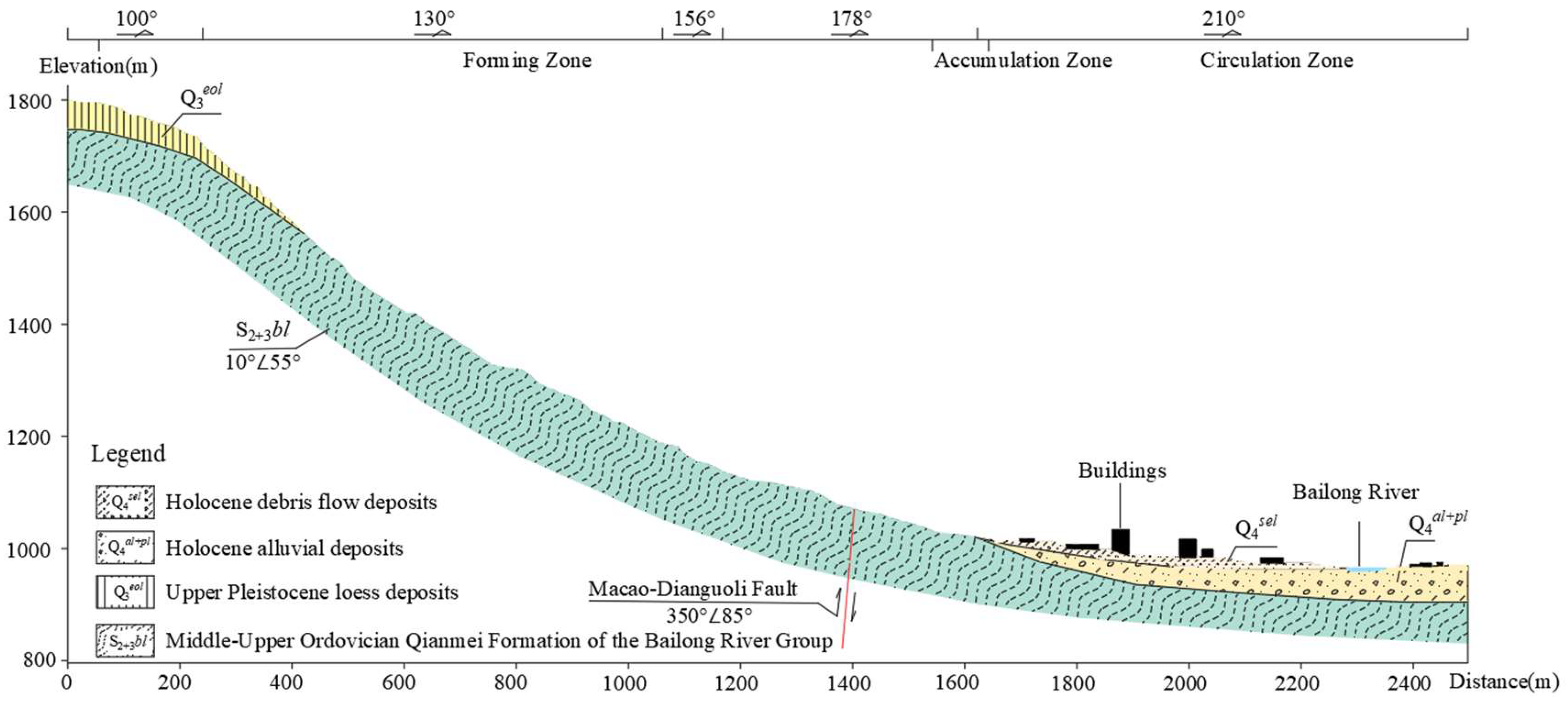
The Huiyazi catchment is located on the right bank of the Bailong River, north of the Qilian Mountains Cement Factory, in Huiyazi Village, Yaozhai Town, Wudu District, Longnan City. The geographical coordinates are 33°24′56.20″ N and 104°53′44.60″ E. The surrounding area is a high-mountain landform with erosional structures (Figure 1), with an average slope of approximately 34°. The elevation of the mountain peak is around 1957 m, while the elevation at the foot of the slope in the Qilian Mountains Cement Factory area ranges from 1003 to 1026 m, and the normal water level of the Bailong River is 996 m. The Huiyazi debris flow is leaf-shaped with a main channel length of about 1.5 km. The elevation at the head of the channel is 1826 m, while the elevation at the outlet is 1022 m, resulting in a longitudinal slope ratio of 536‰ (Figure 2). The length of the branch channels is 440~500 m, with an average longitudinal slope ratio of 491‰. The watershed area is approximately 1.2 square kilometers. The upper reaches of the channel exhibit intense incision, with a narrow and steep V-shaped valley, while the lower reaches feature a gradually widening channel with a width of about 10 to 30 m, reaching up to 50 to 60 m at its widest point. The slope gradually becomes gentler. Moreover, the area where the debris flow occurs exposes phyllites from the Silurian Bailong Formation, with the upper part of the mountain covered by loess, and the foot of the slope consisting of the Bailong River alluvial terrace at the second level and debris flow alluvial fans. The Huiyazi debris flow is a typical slope-type debris flow, and the difference between the formation area and the circulation area is not obvious. The phyllite on both sides of the channel exhibits strong weathering and severe exfoliation, and a large number of loose depositions are distributed on the slope surface. Multiple landslides develop along the channel from top to bottom, providing abundant material sources for debris flows.
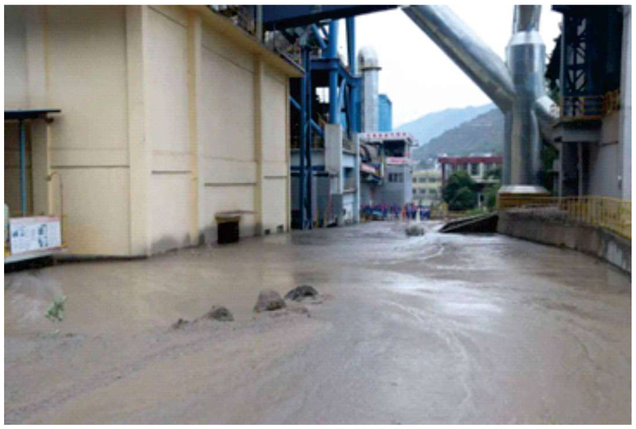
Continuous heavy rainfalls, torrential rains, and repeated intense rainfall events occurred in the middle and upper reaches of the Bailong River Basin, including Zhuoqu, Wudu, and Wen counties on 17 August 2020. During this period, the region experienced numerous short-term heavy rainfall events that were intense, extensive, and persistent. According to rainfall data provided by the Longnan City Meteorological Bureau, the rainfall on the 17th Zhongloutan Street, Wudu District, was 97 mm. This rainfall triggered a massive flash flood and debris flow disaster in a century-old area. According to field surveys and interviews, excessive rainfall resulted in the flooding of the cement plant area. The flow depth on the factory road surface reached approximately 1.6 m, and in the drainage ditch, it even reached about 1.8 m. This caused the cement plant to cease production for over 40 days. The situation is particularly severe, with direct economic losses amounting to CNY 90.5 million and indirect losses reaching CNY 210 million.

3. Method and Data Preprocessing

3.1. Method

3.1.1. FLO-2D Model

The FLO-2D software model was proposed by O’Brien in 1988. It divides the DEM into regular and equal-sized grids, and the elevation value and roughness in each grid are unique and have the same reduction coefficient and area. By solving the motion equation and continuity equation for each grid, the changes in debris flow in each grid can be obtained, including velocity, deposition depth, and so on. The FLO-2D model follows the principle of mass conservation, ensuring that the total mass within each grid remains constant, and determines the volume changes in solids and fluids within each grid based on volume concentration. The distribution of debris flow can be determined by parameters such as flow velocity and depth. The accuracy of numerical simulation of debris flow using FLO-2D has also been verified by many scholars. There are several advantages of using FLO-2D for debris flow simulation: ① simple operation; ② short calculation time; ③ various resistances can be simulated; ④ the results include mud level, flow velocity, and intensity; and ⑤ the results can be post-processed in GIS. The fundamental assumptions of simulating debris flow motion include the following: ① the motion process of the fluid is a shallow water wave motion mode; ② its motion equation satisfies the fixed-length flow equation; ③ the distribution of fluid pressure is a hydrostatic pressure distribution; ④ the elevation and Manning coefficient within each calculation grid are unique; and ⑤ the flow pattern within the differential time interval is steady flow. The governing equations of the FLO-2D software are the constitutive fluid equations, including continuity equations and motion equations (dynamic wave momentum equations).
(1)
Continuity equation:
h t + h V x = I
where h is flow depth, t is simulation time, I is effective rainfall intensity, and V is the average depth flow velocity in the X direction among the eight water flow directions. This equation governs the conservation of mass in the fluid during the simulation. Subsequently, the one-dimensional continuity equation was extended to a two-dimensional plane continuity equation:
h t + ( u h ) x + ( v h ) y = I
where u is the average flow velocity in the X direction, and v is the average flow velocity in the Y direction.
(2)
Equations of motion:
The equation of motion in one dimension is as follows:
S f = S o h x V V g x V g t
where Sf represents the friction slope along the X-direction (based on the Manning equation), So is the bed slope, h is the water depth, t is the simulation time, and g is the gravitational acceleration. This equation represents one-dimensional average depth river flow. However, for flat terrains such as floodplains, flow occurs in multiple directions. The one-dimensional motion equation of FLO-2D calculates the average flow velocity passing through the boundary of grid cells in a single direction. Obviously, this clearly does not correspond to the actual situation. Therefore, a two-dimensional motion equation, derived from the one-dimensional motion equation, was developed later:
S f x = S o x h x u g t u u x v u u
S f y = S o y h y v g x u v g x v u g y
where Sfx and Sfy represent the friction slopes in the X and Y directions, and Sox and Soy represent the slopes of the riverbed bottom in the X and Y directions. This two-dimensional equation can calculate the flow of debris flow on a two-dimensional plane.
(3)
Rheological equation:
τ = τ c + τ m c + τ v + τ t + τ d
where τc, τmc, τv, τt, and τd are viscous yield stress, Mohr–Coulomb shear stress, viscous shear stress, turbulent shear force, and discrete shear stress, respectively.
The above equation is rewritten into a dimensionless form as follows:
S f = S y + S v + S t d
where Sf is friction slope, Sy is yield slope, Sv is viscous slope, and Std is turbulence dispersion slope. This equation is mainly used to calculate stress changes.
The first term Sy, yield slope, in the above formula can be rewritten as τ y γ m h .
The second term viscous slope, Sv, can be expressed by the average depth flow velocity u, which can be rewritten as K η u 8 γ m h 2 .
The third term Std represents turbulent dispersion slope expressed as the velocity in terms of equivalent Manning’s coefficient, water depth, and average depth, given by n t d 2 u 2 h 3 / 4 .
Where η is the viscosity coefficient, K is the laminar flow resistance coefficient, γm is the unit weight of debris flow, and ntd is the equivalent Manning coefficient.
The above three equations S y = τ y γ m h , S v = K η u 8 γ m h 2 , and S t d = n t d 2 u 2 h 3 / 4 are substituted into Equation (7) to obtain the dimensionless form of the rheology equation:
S f = τ c γ m h + K η u 8 γ m h 2 + n t d 2 u 2 h 3 / 4
Based on the continuity equation (Equation (2)) and the motion equations (Equations (4) and (5)) on a two-dimensional plane, as well as the rheology equation (Equation (8)), each grid cell in the computational domain is solved to obtain the essential parameters of debris flow motion. Consequently, the results of the debris flow fluid motion process across the entire computational domain are obtained.

3.1.2. Hazard Zoning Model

At present, debris flow hazard classification standards are primarily defined by three factors: flow velocity, flow depth, and occurrence probability. The intensity of debris flows is defined by a combination of flow velocity and flow depth. Identifying hazard zones based solely on the intensity of the hazard is insufficient. Typically, Swiss and Austrian standards are referenced, employing a debris flow hazard zoning model that combines the intensity of debris flows with the frequency of occurrence, categorizing the level of debris flow hazards into three levels: low, medium, and high [28].

3.2. Data Preprocessing

Using high-precision Digital Surface Model (DSM) data with a pixel size of 5 m × 5 m, it was converted into an ASCII format with elevation information recognizable by the FLO-2D software using the conversion tool in ArcToolbox in ARCGIS (10.8). Subsequently, major elements such as boundaries and outflow points of the Huiyazi debris flow were vectorized.
After importing the ASCII data into FLO-2D, the first step is to divide the elevation data grid. To ensure more accurate simulation results and take into account factors such as the area of the Huiyazi debris flow and computation time, the grid cells were determined to be 5 m × 5 m. Following this, vector elements such as watershed boundaries and outflow points were loaded, and elevation values were assigned to the entire Digital Surface Model (DSM), completing the preprocessing of terrain data.

3.2.1. Volumetric Sediment Concentration

Debris flows consist of a mixture of water and solid particles, forming a two-phase flow. Most debris flows contain large solid particles, resulting in an uneven distribution of flow depth and flow direction during movement. These large solid particles not only increase the destructive potential of debris flows but also determine the rheological characteristics of the debris flow body relative to the total volume of the debris flow. Additionally, they have a certain influence on the morphology of debris flow deposition fans. According to the Formula (9) for calculating the volume concentration of debris flow,
C V = γ C γ W γ H γ W
where CV denotes volume concentration, γc denotes specific gravity of solid particles in debris flows/(KN/m3), γw denotes the gravity of water, and γH denotes the gravity of solid matter in debris flows. γc = 17.86 KN/m3, γw = 10 KN/m3, and γH = 25 KN/m3, and thus, CV = 0.524.

3.2.2. Viscosity Coefficient

The simulation in FLO-2D requires the setting of the viscosity coefficient (η) and yield stress τc. The formula is as follows:
η = α 1 e β 1 c v
τ c = α 2 e β 2 c v
According to the formula, obtaining the viscosity coefficient and yield stress only requires determining the correlation coefficients of rheological parameters α1, α2, β1, and β2. The rheological parameters in this study are calculated using the relationship proposed by Wang Yuyi et al. between rheological parameters and the ratio of sediment to water as well as the volume concentration [29].
τ c = 0.021 R n s 0.3 exp [ 19.64 × R n s 0.25 × C v f ]
η = 1.39 × 1 0 4 × R n s 0.47 exp [ 18.07 × R n s 0.13 × C v f ]
Thus, the correlation coefficients of the rheological parameters for the Huiyazi debris flow can be obtained as follows: α1 = 0.0002, α2 = 0.0255, β1 = 16.61, and β2 = 16.71.

3.2.3. Manning’s Coefficient

The Manning coefficient is used to represent the roughness of the ground and its impact on the fluid. Its magnitude greatly affects the simulation of debris flows, and different regions and vegetation covers have significant influences on the Manning coefficient [30]. Referencing suggested values from the FLO-2D software manual and by combining them with field survey results, due to the presence of gravel and sparse vegetation covers in the flow area, a value of 0.05 is chosen for the Manning coefficient. However, in the deposition area where buildings are constructed, the Manning coefficient is larger compared to the flow area, and a value of 0.1 is selected [31].

3.2.4. Resistance Parameter for Laminar Flow

The laminar flow drag coefficient (K) represents the inter-layer frictional force during the stratified flow of debris flows. Combining with the FLO-2D manual, the laminar flow drag coefficient is determined to be 2275.

3.2.5. Simulation Time

Based on field investigations of the runoff depth in the debris flow channel during debris flow events and the recollection of local residents regarding the debris flow, along with data such as basin area and debris flow discharge under different recurrence periods, the simulation time for the Huiyazi debris flow under the four recurrence periods is determined to be 1.2 h.

3.2.6. Inflow Node and Peak Discharge

Debris flows originate from runoff points and flow towards the mouth of the gully, so the selection of the runoff point is crucial [32]. Generally, the formation area of loose debris in the catchment area of each debris flow channel is chosen as the runoff point for numerical simulation, also known as the starting point. Based on field investigations and considering the distribution of loose materials and the characteristics of the catchment area, the runoff point for the Huiyazi debris flow channel is set at the confluence of the tributaries.
The Flow Duration curve is also an important factor determining the accuracy of FLO-2D numerical simulations. Firstly, reference is made to the “Atlas of Isohyetal Maps for Different Periods and Frequencies of Rainstorms in the Mountainous Area of Longnan” to check for different frequency design rainfall amounts for intervals such as 1/6 h, 1 h, 6 h, and 24 h. Secondly, according to the peak flow calculation formula in the “Handbook for Rainstorm and Flood Calculation in Small and Medium-sized Basins in Sichuan Province”, clear water flow is calculated. Then, using the formula for calculating debris flow discharge based on completing the square (14):
Q C = ( 1 + φ ) Q B D
where QB denote the clear water discharge for specific recurrence periods (m3/s), QC denotes the debris flow discharge for the same recurrence interval as QB (m3/s), D denotes obstructive coefficient, 2.65, and φ denotes sediment coefficient.
The calculation formula is as follows:
φ = γ c 10 γ H γ c
where γc denotes specific gravity of solid particles in debris flows/(KN/m3), γH denotes the gravity of solid matter in debris flows, with γc = 17.86 KN/m3 and γH = 25 KN/m3, and thus, φ = 1.1.
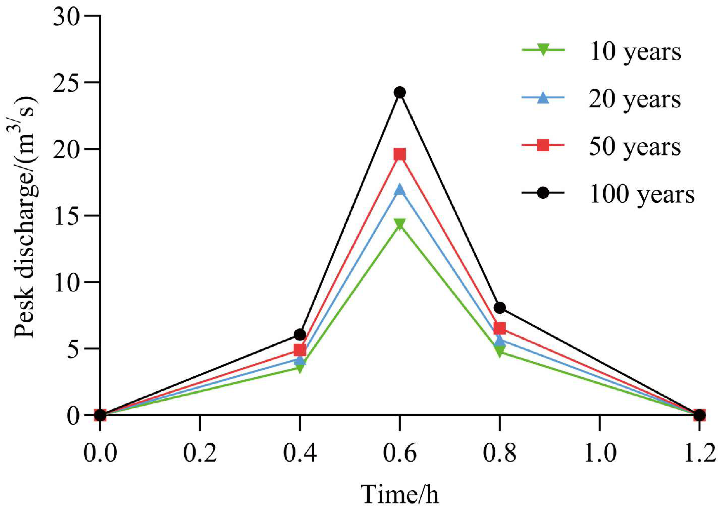
By calculation, the flow process lines of debris flows with different recurrence periods can be obtained (Figure 3).

4. Hazard Assessment of Debris Flow

4.1. Simulation Results

From Figure 4, it can be observed that, under recurrence periods of ten years, twenty years, fifty years, and one hundred years, the maximum flow velocity of the debris flow occurs at locations with significant changes in terrain within the channel. In narrow and straight channels, the highest flow velocity can reach approximately 10.58 m/s, while the flow velocity rapidly decreases as the debris flow exits the channel, ranging from 0 to 6 m/s. Near the factory buildings, the flow velocity is generally between 0 and 1.5 m/s. In the drainage channel, for example, under a one-hundred-year recurrence period, the flow velocity is mainly between 0 and 4.5 m/s, with higher velocities. This is because the flow channels are relatively narrow, resulting in higher flow velocities. However, when the debris flow enters the Bailong River, the flow velocity significantly decreases.
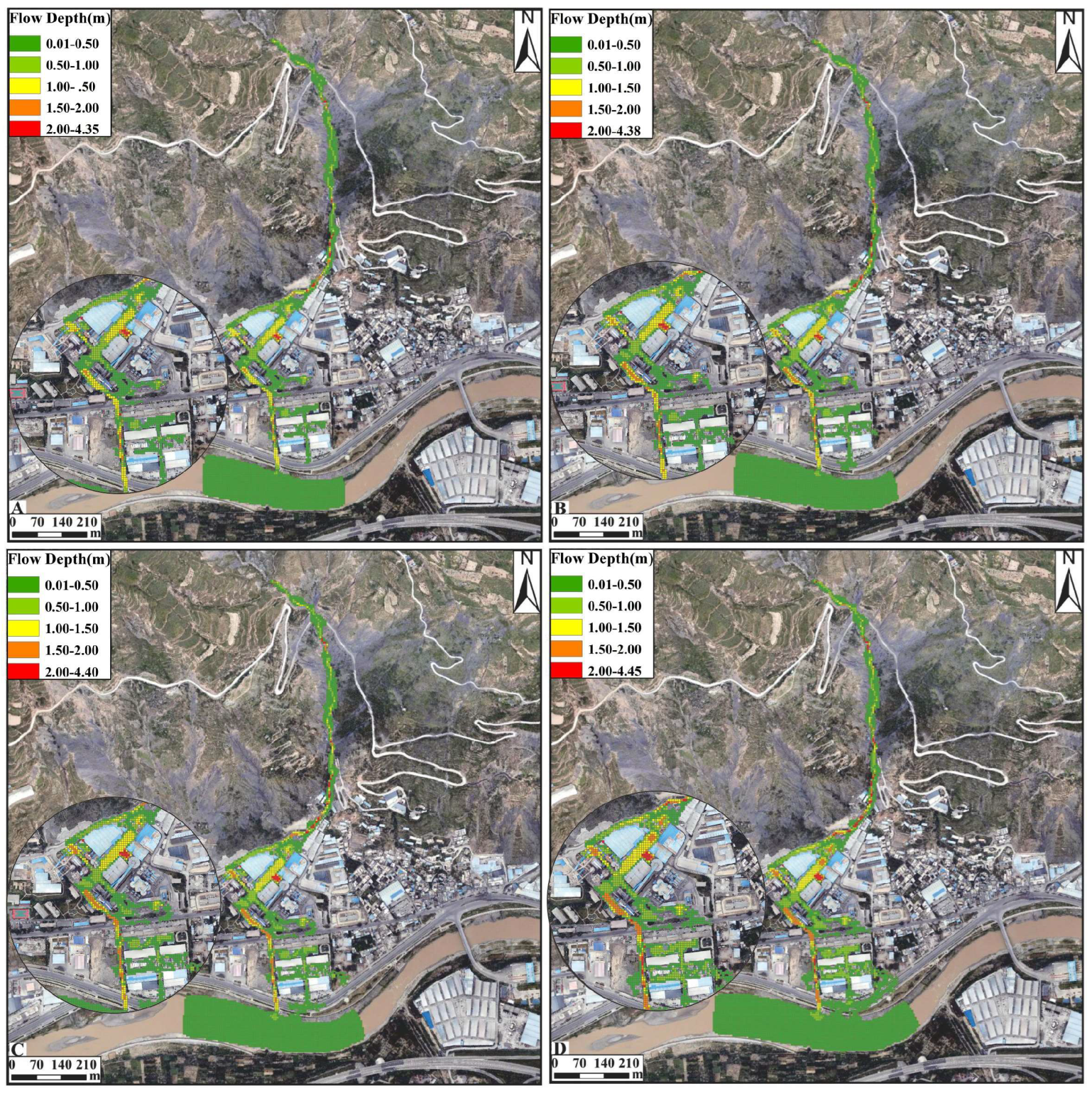
From Figure 5, it can be seen that, under a ten-year recurrence period, the flow depth along the main road in the factory area is generally between 0.5 and 1.5 m, while under twenty-year, fifty-year, and one-hundred-year recurrence periods, the flow depth along the main road is generally between 1.0 and 1.5 m. In some areas, the maximum flow depth can reach 1.55 to 2.44 m under all four recurrence periods. When encountering narrow channels, the flow depth increases. Under a ten-year recurrence period, the flow depth in the drainage channel is between 1.0 and 1.5 m. With the increase in debris flow discharge, the flow depth in the drainage channel gradually increases, reaching approximately 1.5 to 4.45 m under a one-hundred-year recurrence period. On 17 August 2020, after experiencing a one-hundred-year recurrence period, a debris flow erupted in the Huiyazi Gully, with a flow depth of approximately 1.6 m within the Qilian Mountains Cement Factory (Figure 6). Numerical simulation shows that, under a one-hundred-year recurrence period, the average flow depth in the factory area is 1.26 m, with an error rate of 21.25% compared to the actual depth. The accuracy of the numerical simulation results is relatively high when compared to the results of the actual investigation.
When the debris flow enters the Bailong River, it did not cause the deposition of sediment to overflow the river channel and pose a risk of sedimentation to downstream buildings. At this point, the Bailong River acts as a natural barrier to intercept sediment at the foot of the slope.
In the ArcGIS software, the deposition area of the debris flow was accurately delineated by using the results of FLO-2D simulation. Based on different recurrence periods, the characteristic values of the deposition area of the Huiyazi debris flow were determined, as shown in Table 1 below. The study found that, with the increase in the recurrence period, the deposition area, volume, and average deposition thickness all showed a gradually increasing trend.
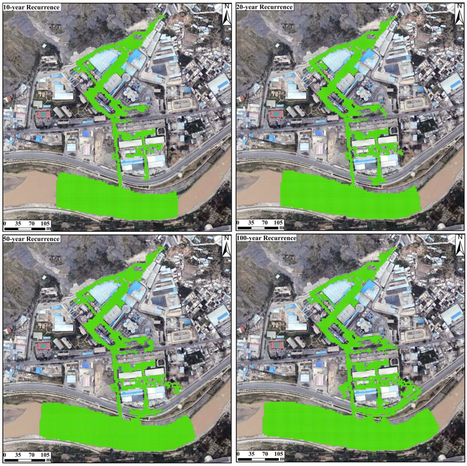
The simulation results of the debris thickness for the four recurrence periods were overlaid onto the satellite imagery. From Figure 7, it can be observed that with the increase in debris flow discharge, the deposition area gradually expands, accumulating around the houses and within the Bailong River. The average deposition thickness varies between 0.36 m and 0.42 m for different recurrence periods, posing a threat to the houses within the deposition area.
Especially in the cement factory, the debris flow flows through the gaps between the buildings, showing evident diversion phenomena. Additionally, the debris flow mainly flows within the Qilian Mountains Cement Factory, with no observed flow on the left or right sides. The main reason for this may be that the debris flow rushes toward the channel mouth, and the left side is closer to the mountain with a narrow channel, and the left channel has a higher elevation than the cement factory channel. This results in the debris flow mainly passing through the cement factory buildings and flowing downward until it enters the Bailong River.

4.2. Assessment of the Degree of Hazard

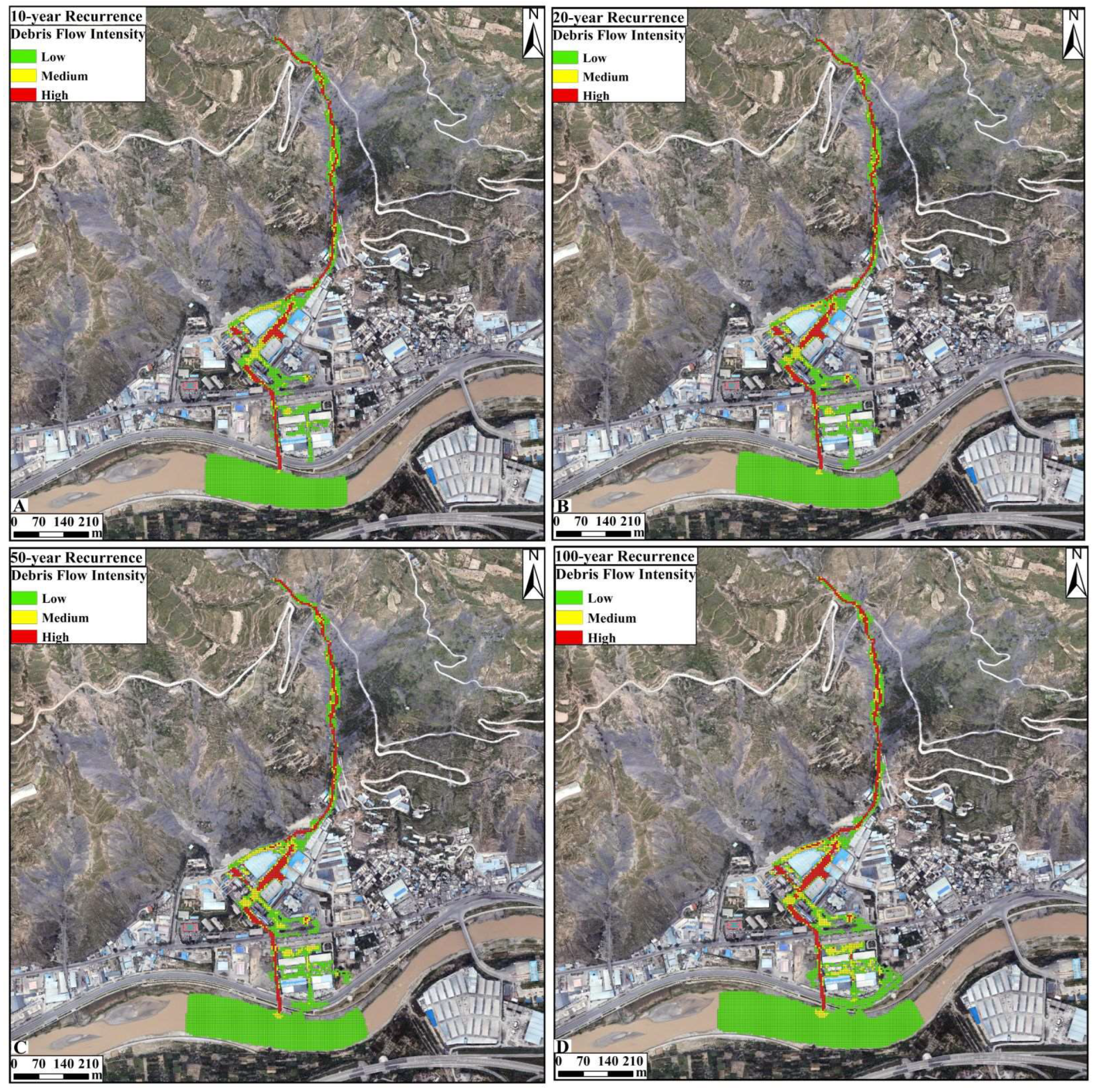
In this study, based on Swiss and Austrian standards, combined with the intensity and occurrence probability of debris flows, the hazard of debris flows is categorized into three levels: low, medium, and high. The debris flow intensity is defined as the maximum simulated depth (H) multiplied by the maximum simulated velocity (V) and the maximum simulation depth (H) [33]. Based on different combinations of H and V, the intensity of the debris flow in Huaiyazi was classified into different levels, as detailed in Table 2. According to the classification criteria in Table 2, the classification results of the intensity of debris flows for different recurrence periods are obtained (Figure 8A–D).
The occurrence probability of debris flows can be calculated using the following equation:
P m = 1 ( 1 1 T ) m
where Pm represents the probability of debris flows occurring within m years, and T represents the recurrence period of debris flows, with m specified as one. The probability of debris flow occurrence is classified as follows: if the probability exceeds 10%, it is considered to be of high frequency; if it falls between 5% and 10%, it is categorized as moderate frequency; a probability range between 2% and 5% indicates low frequency; and if the probability is between 1% and 2%, it is classified as very low frequency.
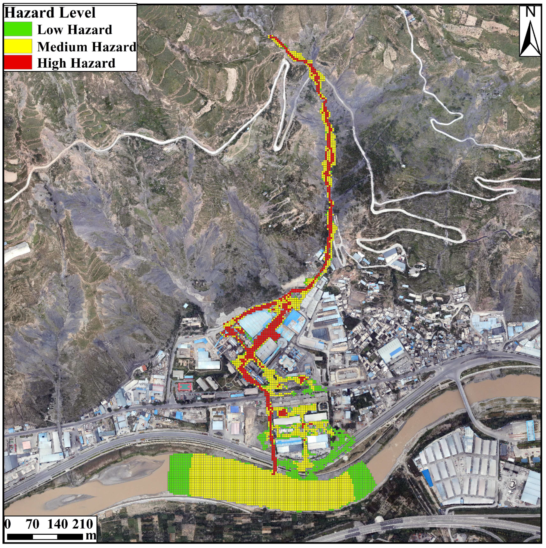
Combining intensity levels with occurrence probability, the hazard of debris flow is categorized (Figure 9). Based on this classification system, a hazard zoning map of the Huiyazi debris flow was created (Figure 10).
(1)
The high hazard areas account for 16.74% of the total area. Due to the uneven width and steep terrain of the mudslide ditch, the blockage of buildings, and the narrow width of the drainage channel, the high-hazard areas are mainly concentrated in the channels, factory buildings, and drainage channels. Damage to the factory buildings is particularly significant due to siltation phenomena. There is a high risk of damage in the event of future mudslides, and it is important to remove silt in a timely manner to prevent further siltation from damaging the factory buildings.
(2)
The medium hazard area accounts for 62% of the area, which occupies the largest area and is mainly located on both sides of the channels, buildings, and within the Bailong River, and although its hazard level is relatively low, the potential hazard of mudslides should not be ignored due to its wide range. Therefore, effective monitoring, early warning, and risk management measures need to be taken for the medium-hazard area in order to mitigate the potential damage caused by mudslides.
(3)
The low hazard area accounts for 21.26% of the area and is mainly located within the buildings and the Bailong River, which is less hazardous to the buildings. However, there is still a need for vigilance and ongoing monitoring and assessment to ensure safety.

5. Discussion

5.1. Comparison of DEM and DSM Simulation Results

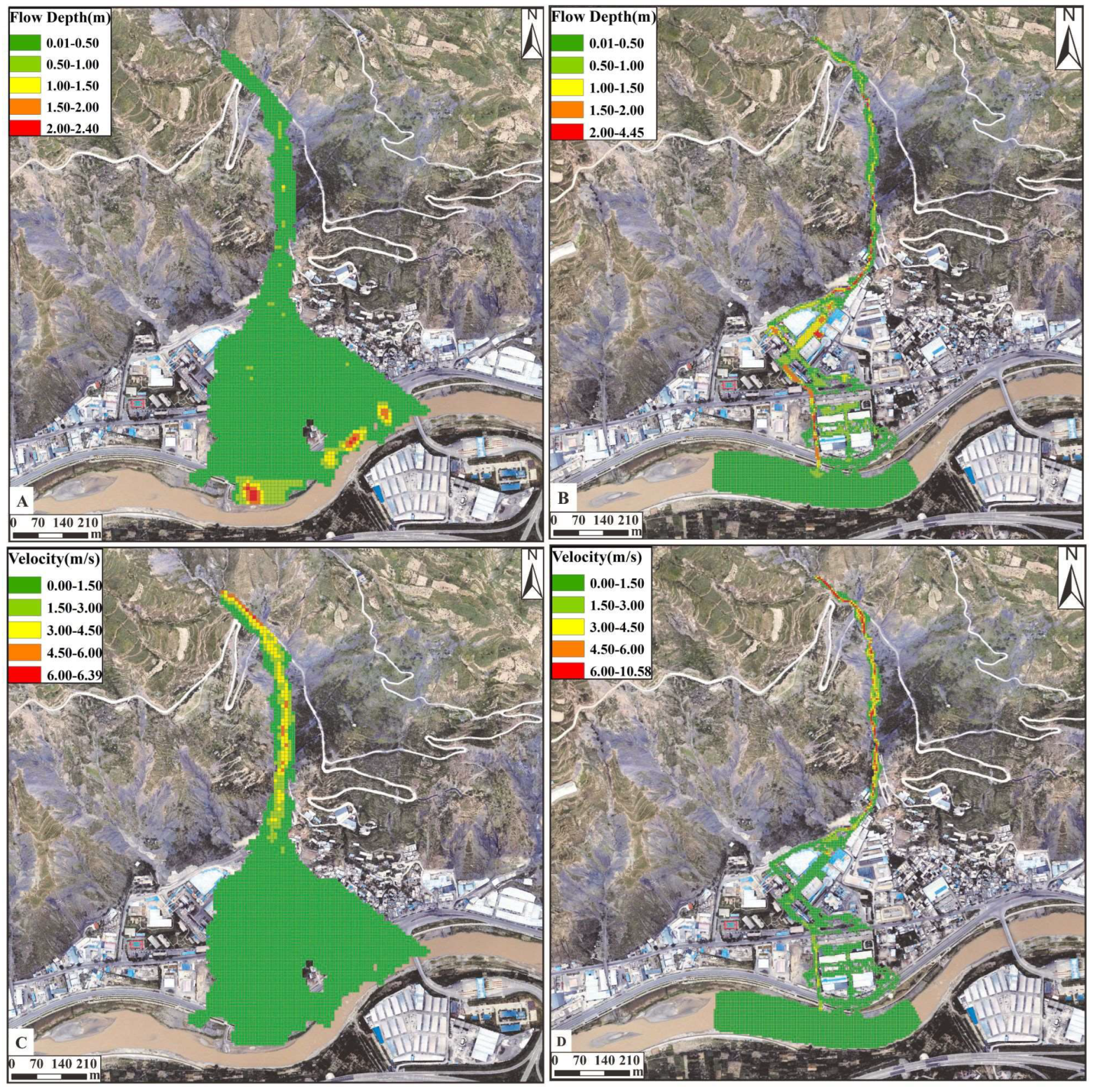
In this research, in order to demonstrate the advantages of DSM (Digital Surface Model) data compared to DEM (Digital Elevation Model) data in simulating debris flow movement characteristics, we selected scenarios of a one-hundred-year recurrence period for the comparison of simulation results between the two.
As illustrated in Figure 11, the DEM simulation results show that the debris flow did not deposit when passing through the cement plant area but instead exhibited a planar flow, which is inconsistent with the actual observed debris flow events. Conversely, the DSM simulation results revealed characteristics of flow diversion and deposition when encountering buildings, aligning with the observed data from the actual debris flow event on 17 August 2020, where approximately 1.6 m of flow depth was recorded on the main road of the cement plant area. Therefore, DSM provides more accurate and realistic simulation results by considering the complexity of surface structures and other features impacting debris flow behavior, which holds significant value for hazard assessment and disaster management.

5.2. Debris Flow Characteristics Analysis and Protective Measure Suggestions

This research simulated the behavior of debris flows in the Huiyazi debris flow under different recurrence periods using the FLO-2D software, revealing significant changes in debris flow velocity and deposition depth with terrain changes. The simulation results indicate that, in narrow and steep channels, the velocity of the debris flows significantly increases, but it rapidly decreases when the flow exits the channel and encounters buildings. This observation is consistent with the findings of Zhang et al., who also reported similar terrain effects on debris flow velocity [34].
Conversely, regarding the depth of the debris flow, it tends to be shallow within narrow channels due to the rapid flow speed that prevents deposition. Upon exiting the channel and encountering obstacles such as buildings, the debris flow exhibits deposition and diversion. This observation aligns with the research by Han et al. on the dynamic characteristics of debris flows in narrow and steep channels, further validating the significant influence of terrain on the movement characteristics of debris flows [35].
This research classified the hazard levels of debris flows based on Swiss and Austrian standards, considering the intensity and probability of occurrences. The results indicate that high hazard areas are primarily concentrated in channels, cement factory areas, and drainage channels. To reduce the potential threat of debris flows to these areas, enhanced protective measures should be implemented, such as reinforcing drainage channels and constructing protective embankments. The Bailong River serves as a natural barrier that effectively intercepts debris flows, suggesting that strengthening protective facilities along both banks of the river, such as building sediment traps and reinforcing riverbanks, could be effective mitigation measures to prevent sediment from affecting downstream buildings. Although the risk in medium hazard areas is relatively lower, their widespread distribution necessitates the implementation of effective monitoring and early warning systems. Additionally, regular hazard assessments should be conducted to identify and mitigate potential threats. For low hazard areas, where the threat to buildings is minimal, basic preventive measures should still be implemented, such as establishing emergency plans and conducting community education to enhance public awareness of disasters and self-help capabilities.

6. Conclusions

In the study, the Huiyazi debris flow in Longnan City is examined as a case study. Using the FLO-2D numerical simulation software, the study simulates the movement and deposition characteristics of debris flows under four different recurrence periods. The main conclusions obtained are as follows:
(1)
Under different recurrence periods, the flow velocities of the debris flow after exiting the gully range from 0 to 6 m/s, with velocities near the factory buildings generally ranging from 0 to 1.5 m/s. The velocities in the drainage channels are relatively higher, typically around 0 to 4.5 m/s. But the flow velocities noticeably decrease after entering the Bailong River. After leaving the gully, the debris flow exhibits distinct diversion, primarily flowing towards the cement plant area. Limited flow is observed on the left and right sides, likely due to the obstruction of the mountainous terrain and narrow channels.
(2)
Under different recurrence periods, the depth of debris deposition in the factory area is generally less than 1.5 m. With an increase in debris flow volume, the depth of deposition gradually increases, with the maximum deposition depth typically occurring within the drainage channels. Upon flowing into the Bailong River, the debris flow does not cause deposition material to cross the river channel, posing a risk of diversion to downstream buildings. At this point, the Bailong River serves as a barrier intercepting sediment deposition at the foot of the slope.
(3)
According to Swiss and Austrian standards, combined with the intensity and probability of debris flow occurrences, the hazard of debris flows is classified into three levels: low, medium, and high. By categorizing the intensity of the Huiyazi debris flow and considering the frequency of occurrences under different recurrence periods, corresponding hazard zone maps were generated. High-hazard areas are mainly concentrated in the channels, factory buildings, and drainage channels, where enhanced protective measures are required. The medium hazard area is primarily distributed along both sides of the channels, buildings, and within the Bailong River, with a widespread distribution and significant potential hazard. The low hazard area is mainly located within buildings and the Bailong River, posing minimal hazard to buildings. Based on terrain and remote sensing images, the main threatened objects for all four recurrence periods are the cement factory and the houses below it, providing valuable insights for debris flow risk management and mitigation.
(4)
Debris flow channels typically lack vegetation or have sparse vegetation cover. Compared to traditional Digital Elevation Model (DEM), high-precision Digital Surface Model (DSM) ensure that the terrain of debris flow channels accurately reflects reality while also preserving digital model information of structures and other vulnerable elements. The simulation results indicate that employing high-precision DSM (Digital Surface Model) for debris flow hazard assessment demonstrates characteristics such as sediment deposition and diversion when encountering buildings in the deposition zone. The movement process and disaster features of debris flows closely resemble real conditions, resulting in more accurate evaluation outcomes.

Author Contributions

Writing—original draft, Y.G.; Writing—review & editing, Z.F.; Supervision, L.W., Y.T. and L.C. All authors have read and agreed to the published version of the manuscript.

Funding

Fine investigation and risk control of geological hazards in typical areas such as the Wujiang River Basin: DD20221748.

Data Availability Statement

Data are contained within the article.

Conflicts of Interest

The authors declare no conflict of interest.

References

  1. Tang, C.; Zhu, J.; Li, W.L.; Liang, J.T. Rainfall-Triggered Debris Flows Following the Wenchuan Earthquake. Bull. Eng. Geol. Environ. 2009, 68, 187–194. [Google Scholar] [CrossRef]
  2. Ouyang, C.; Wang, Z.; An, H.; Liu, X.; Wang, D. An Example of a Hazard and Risk Assessment for Debris Flows—A Case Study of Niwan Gully, Wudu, China. Eng. Geol. 2019, 263, 105351. [Google Scholar] [CrossRef]
  3. Lee, S.H.-H.; Widjaja, B. Phase Concept for Mudflow Based on the Influence of Viscosity. Soils Found. 2013, 53, 77–90. [Google Scholar] [CrossRef]
  4. Wang, Z.F.; Zhang, X.S.; Zhang, X.Z.; Wu, M.T.; Wu, B. Hazard Assessment of Potential Debris Flow: A Case Study of Shaling Gully, Lingshou County, Hebei Province, China. Front. Earth Sci. 2023, 11, 1089510. [Google Scholar] [CrossRef]
  5. Dai, Z.; Wang, L.; Fu, X.; Huang, B.; Zhang, S.; Gao, X.; He, X. Degradation of Typical Reverse Sand-Mudstone Interbedded Bank Slope Based on Multi-Source Field Experiments. Int. J. Environ. Res. Public Health 2023, 20, 2591. [Google Scholar] [CrossRef] [PubMed]
  6. Dai, Z.; Yang, L.; Zhang, N.; Zhang, C.; Zhang, Z.; Wang, H. Deformation Characteristics and Reactivation Mechanism of an Old Landslide Induced by Combined Action of Excavation and Heavy Rainfall. Front. Earth Sci. 2023, 10, 1009855. [Google Scholar] [CrossRef]
  7. Zhang, A.; Dai, Z.; Qin, W.; Fu, X.; Gao, J.; Guo, L.; Liu, L.; Jiang, X.; Wang, H. Risk Assessment of the Xigou Debris Flow in the Three Gorges Reservoir Area. Front. Ecol. Evol. 2023, 11, 1264936. [Google Scholar] [CrossRef]
  8. Hürlimann, M.; Copons, R.; Altimir, J. Detailed Debris Flow Hazard Assessment in Andorra: A Multidisciplinary Approach. Geomorphology 2006, 78, 359–372. [Google Scholar] [CrossRef]
  9. Hungr, O.; McDougall, S.; Wise, M.; Cullen, M. Magnitude–Frequency Relationships of Debris Flows and Debris Avalanches in Relation to Slope Relief. Geomorphology 2008, 96, 355–365. [Google Scholar] [CrossRef]
  10. Yu, X.; Wei, J. Grey system analysis and its application in the forecast of mud-rock flow criticality of Beijing. Zhongzhongguo Dizhizaihai Yu Fangzhi Xuebao 2004, 1, 121–123. [Google Scholar]
  11. Feng, P.; Xiang, L.; Luo, L.; Lei, Q.; Cui, K.; Liang, M. Comparative Analysis of Debris Flow Risk Assessment Based on Disaster Entropy and Analytic Hierarchy Process: A Case Study of Diebu County, Gansu Province. Sci. Technol. Eng. 2023, 23, 12416–12426. [Google Scholar]
  12. Yu, Z.; Deng, Y.; Zhao, P. Evaluation on Fuzzy Mathematics Method for Analyzing Risk of Ridigou Debris Flow. Subgrade Eng. 2016, 1, 44–49. [Google Scholar]
  13. Gu, X.; Chen, H.; Liu, H. Method and application of debris flow hazard assessment based on SIGA-BP neural network. J. Chongqing Jiaotong Univ. 2010, 29, 98–102. [Google Scholar]
  14. Liu, T.; Sun, S.; Zhao, Z.; Zhang, X. Massflow model-based evaluation on effect of engineering treatment of debris flow in Lengzigou Gully. Water Resour. Hydropower Eng. 2020, 51, 195–201. [Google Scholar]
  15. Zhang, F.; Zhang, L.; Zhou, J.; Wang, S. Risk assessment of debris flow in Ruoru Village, Tibet Based on FLO-2D. J. Water Resour. Water Eng. 2019, 30, 95–102. [Google Scholar]
  16. Gong, K.; Yang, T.; Xia, C.; Yang, Y. Assessment on the hazard of debris flow based on FLO-2D: A case study of debris flow in Cutou Gully, Wenchuan, Sichuan. J. Water Resour. Water Eng. 2017, 28, 134–138. [Google Scholar]
  17. Wang, Z.; Chang, M.; Liu, P.; Xu, L. Hazard assessment of typical gully debris flow in Anning river:A case study at the Lengzi gully. Chin. J. Geol. Hazard Control. 2022, 33, 31–38. [Google Scholar]
  18. Quan Luna, B.; Blahut, J.; Van Westen, C.J.; Sterlacchini, S.; Van Asch, T.W.J.; Akbas, S.O. The Application of Numerical Debris Flow Modelling for the Generation of Physical Vulnerability Curves. Nat. Hazards Earth Syst. Sci. 2011, 11, 2047–2060. [Google Scholar] [CrossRef]
  19. Peng, S.-H.; Lu, S.-C. FLO-2D Simulation of Mudflow Caused by Large Landslide Due to Extremely Heavy Rainfall in Southeastern Taiwan during Typhoon Morakot. J. Mt. Sci. 2013, 10, 207–218. [Google Scholar] [CrossRef]
  20. Gentile, F.; Bisantino, T.; Trisorio Liuzzi, G. Debris-Flow Risk Analysis in South Gargano Watersheds (Southern-Italy). Nat. Hazards 2008, 44, 1–17. [Google Scholar] [CrossRef]
  21. Franco-Ramos, O.; Ballesteros-Cánovas, J.A.; Figueroa-García, J.E.; Vázquez-Selem, L.; Stoffel, M.; Caballero, L. Modelling the 2012 lahar in a sector of Jamapa Gorge (Pico de Orizaba Volcano, Mexico) using RAMMS and Tree-Ring evidence. Water 2020, 12, 333. [Google Scholar] [CrossRef]
  22. Hussin, H.Y.; Quan Luna, B.; Van Westen, C.J.; Christen, M.; Malet, J.P.; Van Asch, T.W. Parameterization of a numerical 2-D debris flow model with entrainment: A case study of the Faucon catchment, Southern French Alps. Nat. Hazards Earth Syst. Sci. 2012, 12, 3075–3090. [Google Scholar] [CrossRef]
  23. Horton, A.J.; Hales, T.C.; Ouyang, C.; Fan, X. Identifying post-earthquake debris flow hazard using Massflow. Eng. Geol. 2019, 258, 105134. [Google Scholar] [CrossRef]
  24. Choi, S.K.; Park, J.Y.; Lee, D.H.; Fan, X. Assessment of barrier location effect on debris flow based on smoothed particle hydrodynamics (SPH) simulation on 3D terrains. Landslides 2021, 18, 217–234. [Google Scholar] [CrossRef]
  25. An, H.; Ouyang, C.; Wang, F.; Xu, Q.; Wang, D.; Yang, W.; Fan, T. Comprehensive analysis and numerical simulation of a large debris flow in the Meilong catchment, China. Eng. Geol. 2022, 298, 106546. [Google Scholar] [CrossRef]
  26. Lin, J.Y.; Yang, M.D.; Lin, B.R.; Lin, P.S. Risk assessment of debris flows in Songhe Stream, Taiwan. Eng. Geol. 2011, 123, 100–112. [Google Scholar] [CrossRef]
  27. Notti, D.; Giordan, D.; Cina, A.; Manzino, A.; Maschio, P.; Bendea, L. Debris flow and rockslide analysis with advanced photogrammetry techniques based on high-resolution RPAS data. Ponte Formazza case study (NW Alps). Remote Sens. 2021, 13, 1797. [Google Scholar] [CrossRef]
  28. García, R.; Rodríguez, J.J.; O’Brien, J.S. Hazard Zone Delineation for Urbanized Alluvial Fans. In Critical Transitions in Water and Environmental Resources Management; American Society of Civil Engineers: Salt Lake City, UT, USA, 2004; pp. 1–10. [Google Scholar]
  29. Wang, Y.Y.; Zhan, Q.D.; Han, W. Stress-strain properties of viscous debris flow and determination of volocity parameter. Chin. J. Geol. Hazard Control 2003, 14, 9–13. [Google Scholar]
  30. Crosta, G.B. Failure and ¯ow Development of a Complex Slide: The 1993 Sesa Landslide. Eng. Geol. 2001, 59, 173–199. [Google Scholar] [CrossRef]
  31. O’Brien, J.S. FLO-2D User Manual; FLO-2D Software, Inc.: Nutrioso, AZ, USA, 2018. [Google Scholar]
  32. Zhang, H.W.; Liu, F.Z.; Wang, J.C. Hazard assessment of debris flows in Kongpo Gyamda, Tibet based on FLO-2D numerical simulation. J. Geomech. 2022, 28, 306–318. [Google Scholar]
  33. Chang, M.; Tang, C.; Van Asch, T.W.J.; Cai, F. Hazard assessment of debris flows in the Wenchuan earthquake-stricken area, South West China. Landslides 2017, 14, 1783–1792. [Google Scholar] [CrossRef]
  34. Zhang, Y.X.; Gan, J. Numerical simulation of debris flow runout using Ramms: A case study of Luzhuang Gully in China. Comput. Model. Eng. Sci. 2019, 121, 981–1009. [Google Scholar]
  35. Han, M.; Hu, T.; Wang, Y.; Hong, M. Dynamics Character and River-Blocking Analysis of Narrow-Steep Channels Debris Flow in Wenchuan Earthquake Region—Illustrated with Case of Mozi Gully along Duwen Freeway. J. Eng. Geol. 2016, 24, 559–568. [Google Scholar]
Figure 1. Engineering geological plan of Huyazi debris flow.
Water 16 01349 g001
Figure 2. Geologic profile of Huyazi debris flow.
Water 16 01349 g002
Figure 3. Flow hydrograph of the debris flow for different recurrence periods.
Water 16 01349 g003
Figure 4. The debris flow velocity for different recurrence periods: (A) 10-year recurrence periods, (B) 20-year recurrence periods, (C) 50-year recurrence periods, and (D) 100-year recurrence periods.
Water 16 01349 g004
Figure 5. The flow depth of debris flow for different recurrence periods: (A) 10-year recurrence periods, (B) 20-year recurrence periods, (C) 50-year recurrence periods, and (D) 100-year recurrence periods.
Water 16 01349 g005
Figure 6. “17 August 2020” Huyazigou debris flow silting site.
Water 16 01349 g006
Figure 7. Comparison of debris flow deposition area under different recurrence periods.
Water 16 01349 g007
Figure 8. Debris flow intensity simulation for different recurrence periods. (A) 10-year recurrence periods, (B) 20-year recurrence periods, (C) 50-year recurrence periods, and (D) 100-year recurrence periods.
Water 16 01349 g008
Figure 9. Classification of the degree of hazard for debris flows in the study area.
Water 16 01349 g009
Figure 10. Hazard zones of the Huyazigou debris flow.
Water 16 01349 g010
Figure 11. Comparison of DEM and DSM results under one-hundred-year recurrence period. (A) DEM Flow depth results; (B) DSM Flow depth results, (C) DEM Velocity results, (D) DSM Velocity results.
Water 16 01349 g011
Table 1. Characteristic values of debris flow deposition areas under different recurrence periods.
Recurrence
Periods/Years
Deposition Area (km2)Deposition Volume (×104 m3)Average Deposition
Thickness (m)
100.0682.440.36
200.0782.930.38
500.0873.420.39
1000.1024.260.42
Table 2. Debris flow intensity classification.
Debris Flow IntensityMaximum Depth H (m)RelationMaximum Depth H
Multiplied by Maximum Velocity (V) (m2/s)
HighH ≥ 1ORVH ≥ 1
Medium0.5 ≤ H < 1AND0.5 ≤ VH ≤ 1
Low0 ≤ H < 0.5ANDVH < 0.5
Disclaimer/Publisher’s Note: The statements, opinions and data contained in all publications are solely those of the individual author(s) and contributor(s) and not of MDPI and/or the editor(s). MDPI and/or the editor(s) disclaim responsibility for any injury to people or property resulting from any ideas, methods, instructions or products referred to in the content.