Article

Analysis of Stress Characteristics of a Vertical Centrifugal Pump Based on Fluid-Structure Interaction

1
Hunan Water Resources and Hydropower Survey, Design, Planning and Research, Co., Ltd., Changsha 410007, China
2
College of Energy and Electrical Engineering, Hohai University, Nanjing 211100, China
3
Hunan Provincial Water Resources Development and Investment Co., Ltd., Changsha 410007, China
*
Author to whom correspondence should be addressed.
Water 2023, 15(24), 4269; https://doi.org/10.3390/w15244269
Submission received: 13 November 2023 / Revised: 8 December 2023 / Accepted: 11 December 2023 / Published: 13 December 2023
(This article belongs to the Special Issue Advances in Hydrodynamics of Water Pump Station System)

Abstract

:
Vertical centrifugal pumps play a crucial role in numerous water conservancy projects. However, their continuous operation can lead to the development of cracks or even fractures in some centrifugal pump blades, resulting in a substantial adverse impact on the operation of the pumping station unit and jeopardizing safe production. This study employs the fluid-structure interaction method to comprehensively investigate the modal characteristics of the impeller, both in an air environment and immersed in water. Furthermore, the analysis of static and dynamic stress attributes is conducted. The natural frequency of the impeller when submerged in water is significantly lower than its frequency in an air medium, typically accounting for approximately 0.35 to 0.46 of the air-based natural frequency. There are conspicuous stress concentrations at specific locations within the system, specifically at the rounded corners of the blade back exit edge, the impeller front cover, the middle of the blade inlet edge, and the junction where the blade interfaces with the front and back cover. It is crucial to underscore that when the system operates under high-flow or low-flow conditions, there is a pronounced stress concentration at the interface between the impeller and the rear cover plate. Any deviation from the intended design conditions results in an escalation of equivalent stress levels. Through dynamic stress calculations during a single rotational cycle of the impeller, it is discerned that the cyclic nature of stress at the point of maximum stress is primarily influenced by the number of blades and the rotational velocity of impeller. This research carries significant implications for effectively mitigating blade fractures and cyclic fatigue damage, thereby enhancing the operational reliability of vertical centrifugal pumps in water conservancy applications.

1. Introduction

The increasing prevalence of large centrifugal pumps can be attributed to the successive implementation of cross-basin water transfer projects, extensive irrigation and drainage initiatives, and the development of nuclear power plants. With the increasing size of the centrifugal pump impellers, the pump blade cracking problem has become particularly prominent, for example, the blade cracking results in certain economic losses in the Dongjiang-Shenzhen Water Supply Project of China as well as the Grand Coulee Hydroelectric Power Station project of America [1,2].
Many studies have shown that the causes of blade fatigue fracture are the residual stresses, static stresses and vibration alternating variable stresses acting on the blade, and the expansion of microcracks and cracks caused by the cumulative damage of the impeller under its action [3,4,5]. Therefore, stress characterization of large centrifugal pumps is of great significance for the prevention of blade cracks.
The process of stress characterization encompasses the interplay between fluid and solid domains, typically employing a coupled fluid-structure methodology. Currently, more studies use the coupling of Computational Fluid Dynamics (CFD) and Finite Element Analysis (FEA) for fluid-structure interaction [6,7,8]. CFD is used to simulate the flow inside the fluid, while the FEA method is used to analyze the structural response of the pump. The combination of these two methodologies facilitates the dynamic interaction between the fluid and the structure. Researchers usually use commercial software or self-developed coupled solvers to realize it. This approach allows flow-induced vibrations, stress distributions, and the effect of pump structural deformation on flow performance to be considered in a single simulation [9,10,11].
The intrinsic frequency and intrinsic mode of vibration of an undamped system are called the intrinsic modes of the system [12,13]. The investigation of impeller mechanical modal issues holds considerable importance. When the water excitation frequency such as Karman vortex is equal or similar to a certain order of the impeller mechanical intrinsic frequency, resonance occurs, which results in unit vibration and rotor blade cracking problems [14,15,16]. Krzemianowski [17,18] used a three-dimensional finite element method with full fluid-structure interaction to investigate the modal features of a mixed-flow rotor in aqueous medium. The vibration characteristics of the runner in water, such as self-oscillation frequency and vibration mode, were obtained. The results show primary inherent frequency of the runner when submerged in water has a resemblance to the rotational frequency of the blades, and the Carmen vortex frequency at rated condition is close to the higher-order intrinsic frequency of the runner. This proximity significantly increases the likelihood of inducing resonance in the structure, perhaps resulting in the formation of cracks. Zhou [19,20,21] adopted the displacement-velocity potential format of the finite element method without considering the mesh variation and used the Galerkin method of the weighted residual method to investigate the vibration characteristics of a coupled runner in a water medium. Galerkin’s method to perform sequential coupling calculations for the coupled system. A comprehensive analysis is conducted to examine how the flow velocity field influences the vibrational properties of the blades, and the method of calculating the added mass and the factors affecting the added mass are analyzed. B Hübner [22,23] calculated the intrinsic frequency and intrinsic vibration pattern of a hydraulic turbine in water using the acoustic-hydraulic equations, and examined the impact of the vibration pattern caused by the flow, including the flow within the intricate and unstable flow regime. To accomplish this, he utilized the partitioned fluid-structure interaction method. By coupling the fluid flow, the nonlinear solids as a whole calculate the dynamic stresses applied to the solids and analyze the hydro elastic instability of elastomers.
The bearer of the hydro-mechanical runner, water, produces a complex hydraulic excitation on its action, and people have been actively seeking methodologies to determine the stress properties of runner blades resulting from hydraulic excitation. Nowadays, ANSYS software is one of the more commonly used software for calculating fluid structure [24,25,26]. Kan [27] used the flow field and structure to compute and examine the flow field of the axial pump impeller, as well as the strength characteristics of the runner body, and the distribution of stresses was obtained. The research findings indicate a precise alignment between the regions of stress concentration and the specific sites where fracture formation occurs. Quan [28] analyzed the static stress and vibration pattern of the inducer on the basis of the results of three-dimensional numerical calculations of the full flow channel of the high-speed centrifugal pump, the results show that, when subjected to water pressure, the blade deformation reaches its highest displacement in close proximity to the outside edge of the blade outflow edge. Additionally, the region where the blade and the hub are connected demonstrates the utmost magnitude of comparable stress. It is worth noting that blade deformation significantly impacts the vibration characteristics. Egusquiza [29,30] employed the sequential fluid-structure coupling technique to assess the stress characteristics of the runner blade across different operational scenarios. The findings indicate a predominantly linear relationship between the maximum static stress of the runner blade and the turbine power in the majority of working conditions. The maximum static stress of the runner blade under various water heads in the construction of a Francis turbine was determined by Chen [31]. The analysis of the runner static stress distribution at various water heads during rated output reveals that the highest stress occurs at the junction between the blade outlet edge and the upper crown. Furthermore, it indicates a negative correlation between the water head and the highest static stress value. Menéndez [32] carried out static stress and deformation calculations of a pump-turbine and found that the highest static stress is observed on the impeller pressure surface at the junction of the blades and the hub. Additionally, the maximum deformation of the impeller increases as the blade radius increases. Li [33] obtained the stress strain of the impeller structure, and the pressure and flow velocity distribution of the flow field through the simulation of the coupling of the impeller blade and the internal flow field. Birajdar [34] employed the idea of sequential fluid-structure coupling to investigate a vertical turbine pump. They utilized the internal non-constant flow field information as mechanical boundary conditions and employed the finite element method to conduct transient analysis. The utilization of the finite element method was also employed in order to investigate the impeller of a large double-suction centrifugal pump. The findings indicate that the dynamic stress distribution pattern on the impeller surface remains largely consistent across various flow conditions. The highest stress point is observed in the root region adjacent to the front cover plate, either at the inlet or outlet side. Furthermore, the dynamic stress reaches its peak under conditions of low flow. Shi [35] carried out the fluid-structure interaction calculation on the runner of a pump and found that the larger stress area was basically the same as that in which the actual cracks appeared. Then the transient dynamic analysis of the runner under dynamic load was carried out, and the Newmark algorithm was used to derive the stress distribution when the guide vane opening was changed, and when the frequency of dynamic load change was large, the dynamic stress was calculated to be roughly around 15–20 MPa, which was closer to the empirical value. The primary cause of blade cracking is attributed to the elevated levels of dynamic stress.
In this paper, the simulation computation of the whole flow channel is conducted for a particular large centrifugal pump. Fine water pressure distribution maps are obtained to provide important basic data for the performance analysis and optimization of the centrifugal pump. Further, a method known as sequential flow-solid coupling is employed to integrate the flow field data collected earlier with the impeller structure for simulation purposes. The objective is to analyze the distribution of structural stress within the impeller under various operating situations. By comprehensively analyzing the stress distributions under multiple operating conditions, the evaluation of the stresses exerted on the impeller is conducted under various operating situations, and possible stress concentration areas are identified.

2. Computational Model and Boundary Conditions

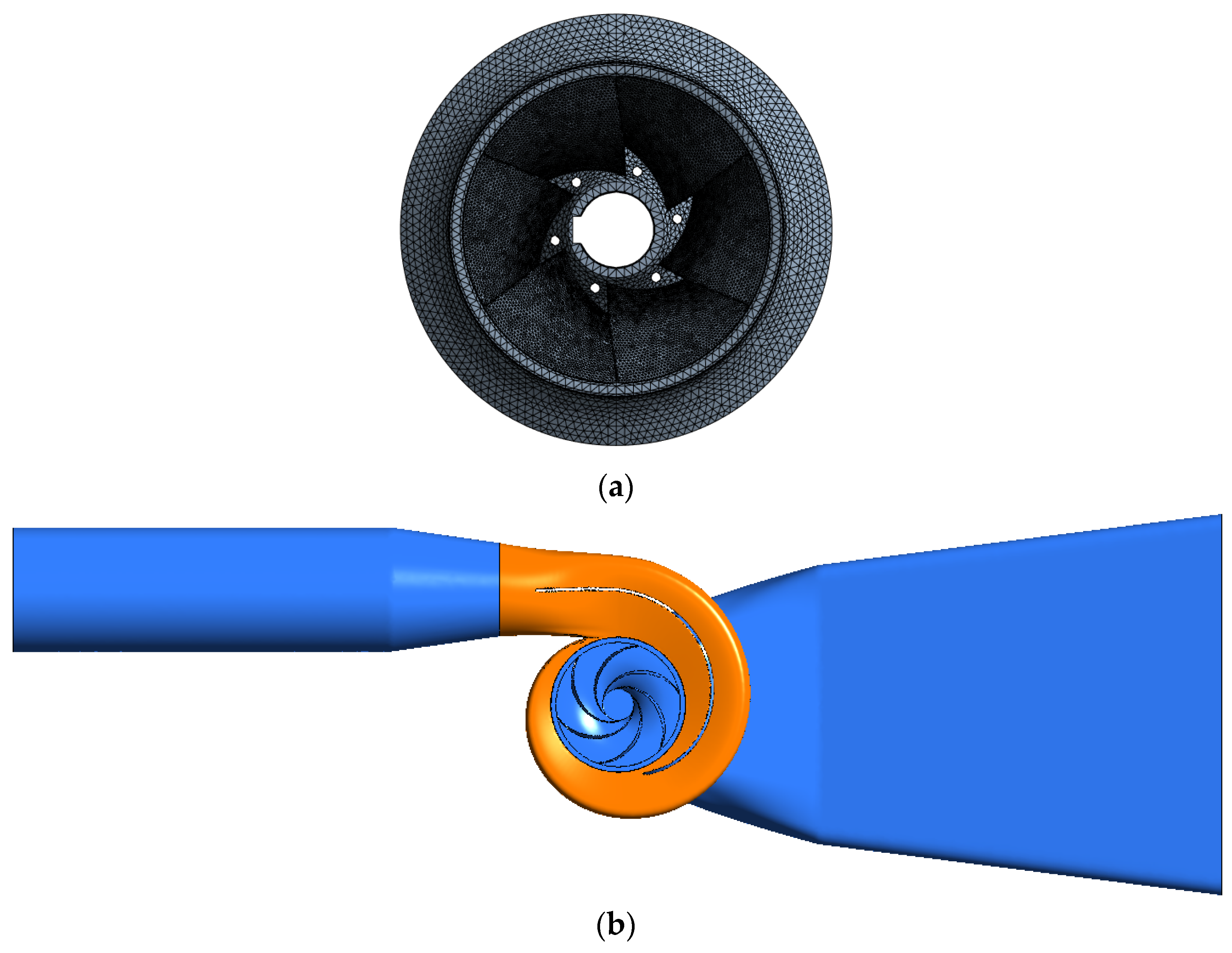
2.1. Computational Models

Pre-processing is the premise of numerical simulation, including solid modeling and mesh division. The centrifugal pump impeller is subjected to modal analysis under the condition of fluid-structure interaction, so in order to accurately simulate the behavior of an impeller and its surrounding water body, it is imperative to incorporate both components into the computational model simultaneously and subsequently partition the mesh accordingly.
Firstly, the centrifugal pump blade is modeled. According to the wood mold drawing, the cylindrical coordinates of each wood mold section control point are extracted and transformed into Cartesian coordinates, the blade is firstly drawn in BladeGen, then the blade is imported into UG 3D modeling software, and the blade solid is generated by sewing the surface. After that, based on the device layout diagram, the impeller front and rear cover plates are observed to be created subsequent to rotation, as indicated by the axial section. Finally, the front and rear cover plates and blades are summed up to generate the impeller entity. The impeller diameter is D = 400 mm, the number of blades is Z = 6, the rated speed is n = 1480 r/min. The impeller solid model and mesh division are shown in Figure 1. The average y+ on the wall is within 30.

2.2. Boundary Conditions

The given boundary condition for the computation of the flow field involves the intake, which is determined by the mass flow rate. On the other hand, the exit condition for the volute is defined by setting the mean static pressure to zero. By employing CFD analysis to evaluate the entire flow channel, a more precise internal flow field may be computed. This enhanced accuracy facilitates the determination of blade surface pressure loads, which in turn contributes to more accurate calculations in the subsequent structural field analysis [36,37,38]. The focus of the structural field calculation is on an individual impeller within a centrifugal pump. Since stress concentration often occurs in the root region, the impeller modeling of the blade and the impeller before and after the cover plate of the transition between the rounded corners of the impeller is also accurately simulated, and in this sensitive area of the mesh refinement, to avoid the calculation process due to the mesh division of the cause of the stress concentration phenomenon that should not be generated [39].
In the structural field calculation, the loads mainly include displacement constraints, water pressure on the blade surface and centrifugal force. The displacement constraint is the fixed hub end face, the gravity and centrifugal force are applied as long as they are defined in ANSYS Workbench [40], and the water pressure at the interface between the fluid and solid is determined by analyzing the outcomes of the comprehensive computation of the flow field in the channel. For the modal analysis of the impeller in water, the fluid-structure interaction needs to be considered, so in addition to the 3D modeling of the impeller, it is also necessary to construct the water region around it. We can visualize this as placing the impeller in a cylindrical body of water, which is to completely submerge the impeller. In order to form a fluid-structure interaction integral finite element model of the impeller submerged in water, we can realize this by constructing a rectangular fluid outside the impeller that is slightly larger than the size of the impeller. When meshing, it is necessary to ensure that the mesh sizes at the fluid-structure interaction interface are consistent. Figure 2 illustrates the comprehensive finite element model of the fluid-solid connection, while the mesh division is visually presented in the same figure. The cases run in the High-Performance Computing Center of Hohai University, using 256 GB of memory and 128 cores for parallel computing. The numerical calculation is carried out on ANSYS CFX 2020.

2.3. Numerical Model
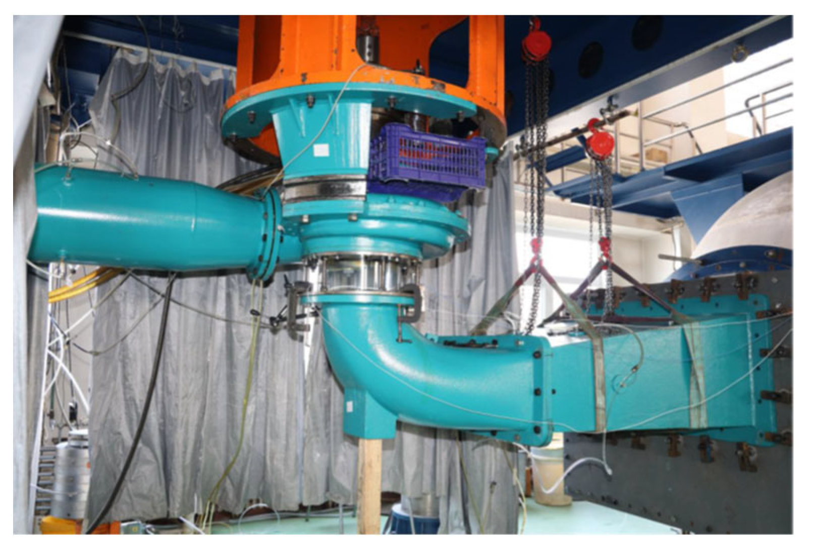
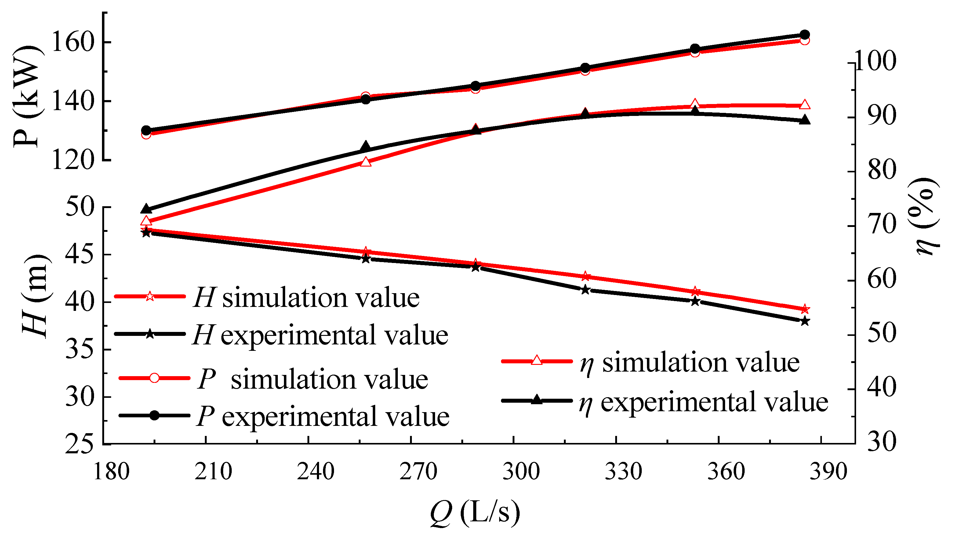
(1) Turbulence Model
The calculation of the flow field adopts SST k-ω turbulence model. The model consists of turbulent kinetic energy transport equation and turbulent dissipation rate transport equation, which has good predictive ability for flow separation under reverse pressure gradient.
ρ k t + ρ u ¯ j k x j = P k D k + x j μ + σ k 3 μ t k x j
ρ ω t + ρ u ¯ j ω x j = P ω D ω + x j μ + σ ω 3 μ t ω x j + 2 ρ 1 F 1 σ ω 2 ω k x j ω x j
Specific parameters can be referenced in reference [38].
(2) Modal Analysis Methods
Equation (3) is the expression of the linear differential equation of structural dynamics:
[ M ] { u ¨ } + [ C ] { u ˙ } + [ K ] { u } = { F ( t ) }
where, [M]; [C]; [K] are the structural mass matrix, damping matrix, and stiffness matrix, respectively. { u ¨ } ; { u ˙ } ; { u } are the acceleration vector, velocity vector, and displacement of each node of the structure; {F(t)} is the external structure load vector.
Modal analysis is a commonly used dynamic analysis method in the field of fluid machinery simulation. It is mainly used to analyze the natural frequency and mode shape of a structure. The natural frequency of a structure is related to many factors, such as the material used by the structure, operating state, the magnitude of the load, etc. When the operating frequency of the centrifugal pump is the same as the natural frequency of the structure, large structural deformation will occur due to structural resonance, which will affect the safety and stability of pump operation in severe cases. Hence, obtaining pump natural frequency and its mode shape by modal analysis can provide a reference for the design of the centrifugal pump.
The linear differential equation of structural dynamics is the same as Equation (3). For modal analysis, the overall load matrix of the structure is {F(t)} = 0, and the damping of the structure can be ignored, that is, [C] = 0. Therefore, the structural dynamic linear differential equations can be expressed by Equation (4):
[ M ] { u ¨ } + [ K ] { u } = { 0 }
From the free vibration of the structure as simple harmonic vibration, the displacement function Equation (5) can be obtained:
x = x sin ( ω t )
the dynamic equation of modal analysis can be obtained as Equation (6):
[ K ] ω 2 [ M ] { x } = { 0 }
To solve Equation (6), the natural frequency and mode shape of the structure are the eigenvalues and eigenvectors, and the structure must be linear. Specific parameters can be referenced in reference [41].

2.4. Validation

The test was conducted at the China Institute of Water Resources and Hydropower Research test rig, as shown in Figure 3. The maximum test head of the test bench is 150 m, the maximum flow rate is 2.2 m3/s, and the efficiency measurement uncertainty is less than ±0.2%. The test bench is equipped with a hydraulic mechanical energy performance test.
Figure 4 compares the calculated and experimental values of the energy characteristic parameters under each working condition. Under the design conditions, the calculated value is more accurate in predicting the head, and the calculated value exceeds the experimental one. The shaft power value obtained through calculation is 0.65 percent greater than that of another value, while the calculated efficiency value is 0.14 percentage points lower than the experimental value. In the case of a low flowrate, the computed values of head, shaft power, and efficiency exhibit a decrease. In the case of a large flowrate, the computed values of head and power exceed the experimental values, while the calculated value of efficiency falls short of the experimental value. Overall, the errors are all within 5%, and the numerical calculation has high reliability.

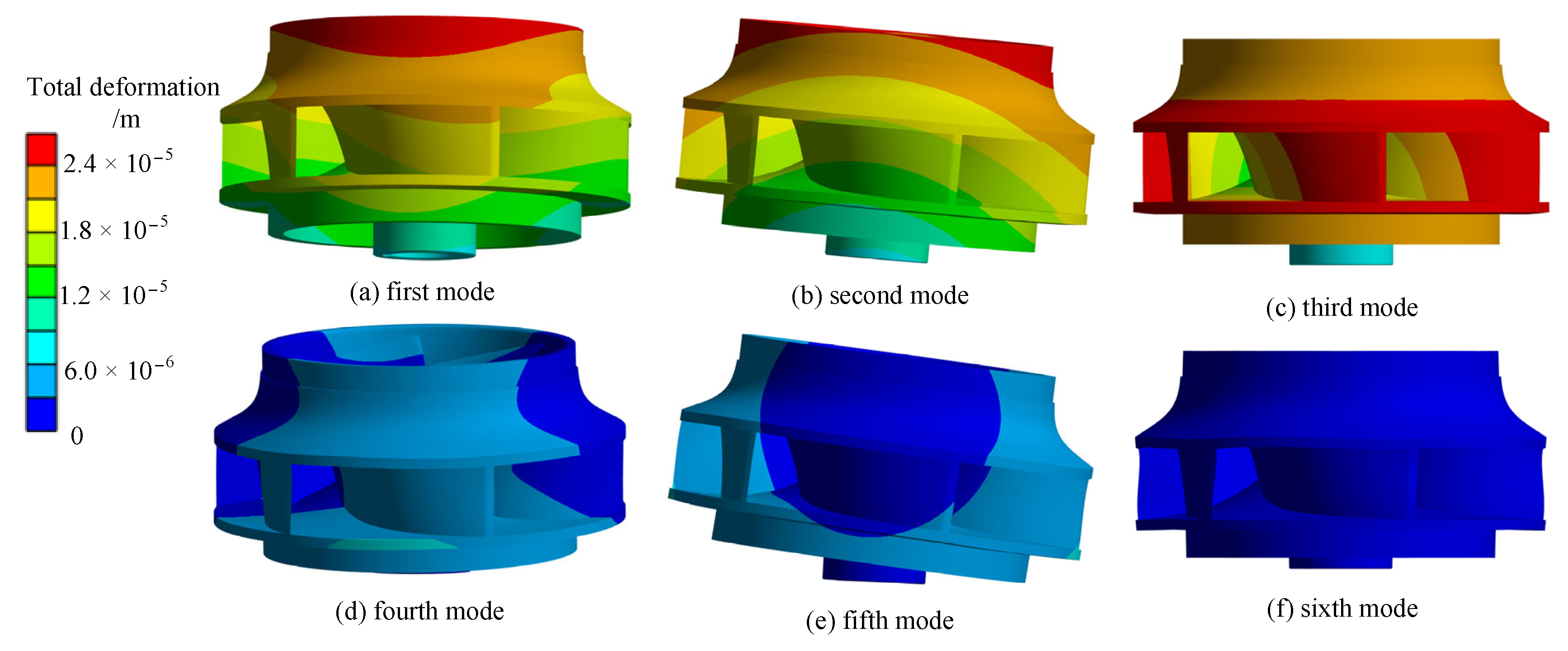
3. Impeller Modal Analysis

3.1. Modal Analysis of Impeller in Air

Table 1 presents the material properties and meshing details of the impeller. Modal analysis is performed to ascertain the inherent frequencies and mode shapes of a structure’s unconstrained oscillations, so only displacement constraints need to be defined and other external loads can be neglected. The full displacement constraint is defined at the end face of the shaft bore of the impeller. According to the modal extraction method, the determination of the modal characteristics of the impeller in an air environment is often performed by employing a mass matrix that is consistent throughout the analysis. So the Block Lanczos algorithm is used in the calculation.

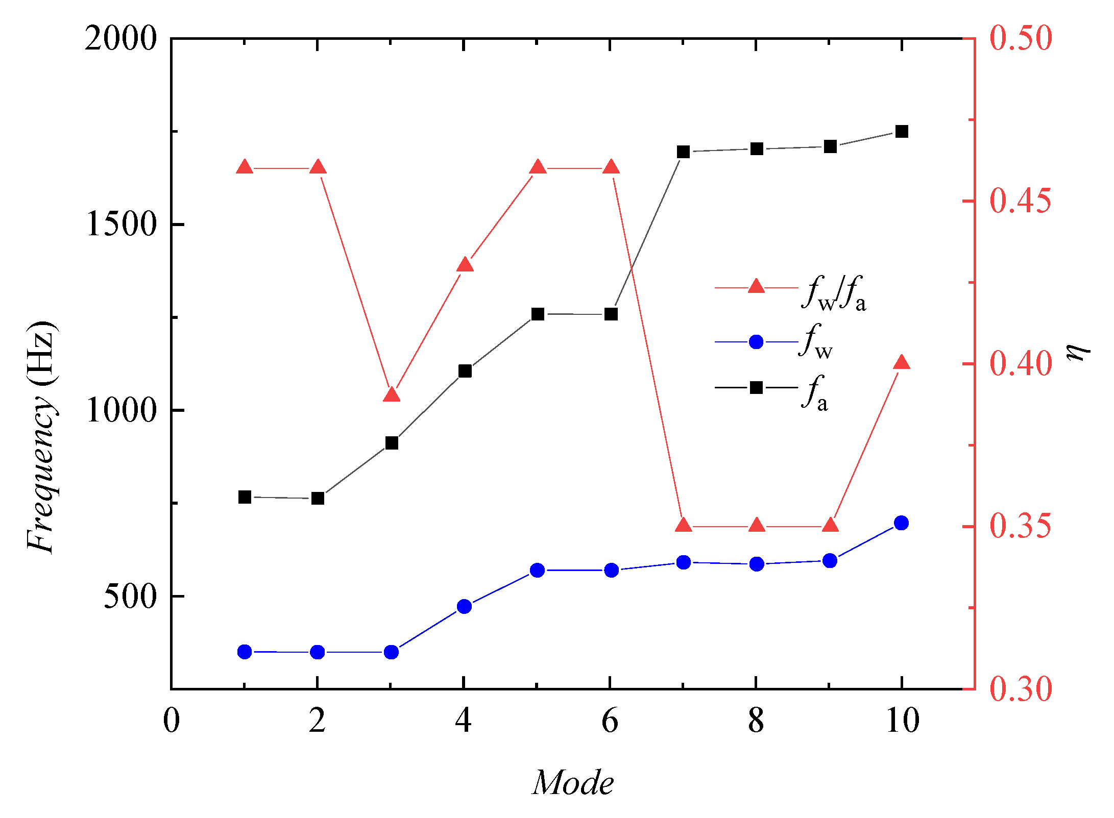
3.2. Modal Analysis of Impeller in Water

The pressure of the Fluid 30 unit is obtained by solving the wave equation. In situations where the pressure distribution of the liquid needs to be observed, using the Fluid 30 unit as the simulation unit is a more appropriate choice [42]. For the modal analysis immersed in water, 8-node tetrahedral solid unit Solid 45 and acoustic unit Fluid 30 are selected for the impeller and the water body, respectively, and the mechanical properties of the water include underwater sound velocity and density. In the actual analysis, the water body is divided into two major categories, one is not in contact with the impeller blades of the unit, and the nodes of these units have only pressure degrees of freedom, only need to apply the surface pressure, where it is a free liquid surface, the pressure is 0; the other is in contact with the impeller surface of the unit, that is, the fluid-structure interaction interface, these units have both pressure degrees of freedom, and displacement degrees of freedom. For the modal analysis in the water, the same only needs to define the full displacement constraints on the end face of the shaft hole of the impeller. According to the theoretical analysis, the unsymmetric method has been selected as the analytical approach to assess the modal characteristics of the impeller immersed in water.
Figure 5 shows the graphs of the first 10 orders of the intrinsic frequency of the impeller in air and water, and Table 2 shows the comparison of the first 10 orders of the intrinsic frequency of the impeller. Where fa denotes the intrinsic frequency in air, fw denotes the intrinsic frequency in water, and η = fw/fa denotes the effect of the water body on the intrinsic frequency of the impeller.
Figure 6 and Figure 7 show the displacement and vibration patterns of each order mode of the impeller in air and water, respectively. The figures show that the displacements and vibration patterns of each order mode of the impeller in water and air are very similar, with the maximum displacements occurring at the outlet of the impeller rear cover plate. The intrinsic frequencies and vibration patterns of the impeller in air and water usually appear in pairs, mainly due to the periodical symmetric structure of the impeller. The 1st and 2nd order vibration pattern are shown as the impeller with the z-axis as the center point, up and down vibration in the axial plane; the 3rd and 4th order vibration pattern is shown as the torsional vibration of the impeller around the z-axis; and the 5th and 6th order vibration pattern is shown as the unilateral bending deformation of the impeller in the axial plane. The impeller’s intrinsic frequency in water is lower than its intrinsic frequency in air due to the extra mass of the water body, but the reduction of the intrinsic frequency of each order is different, as shown in the influence factor, is fluctuating between 0.35 and 0.46.

4. Centrifugal Pump Impeller Full-Condition Stress Characterization

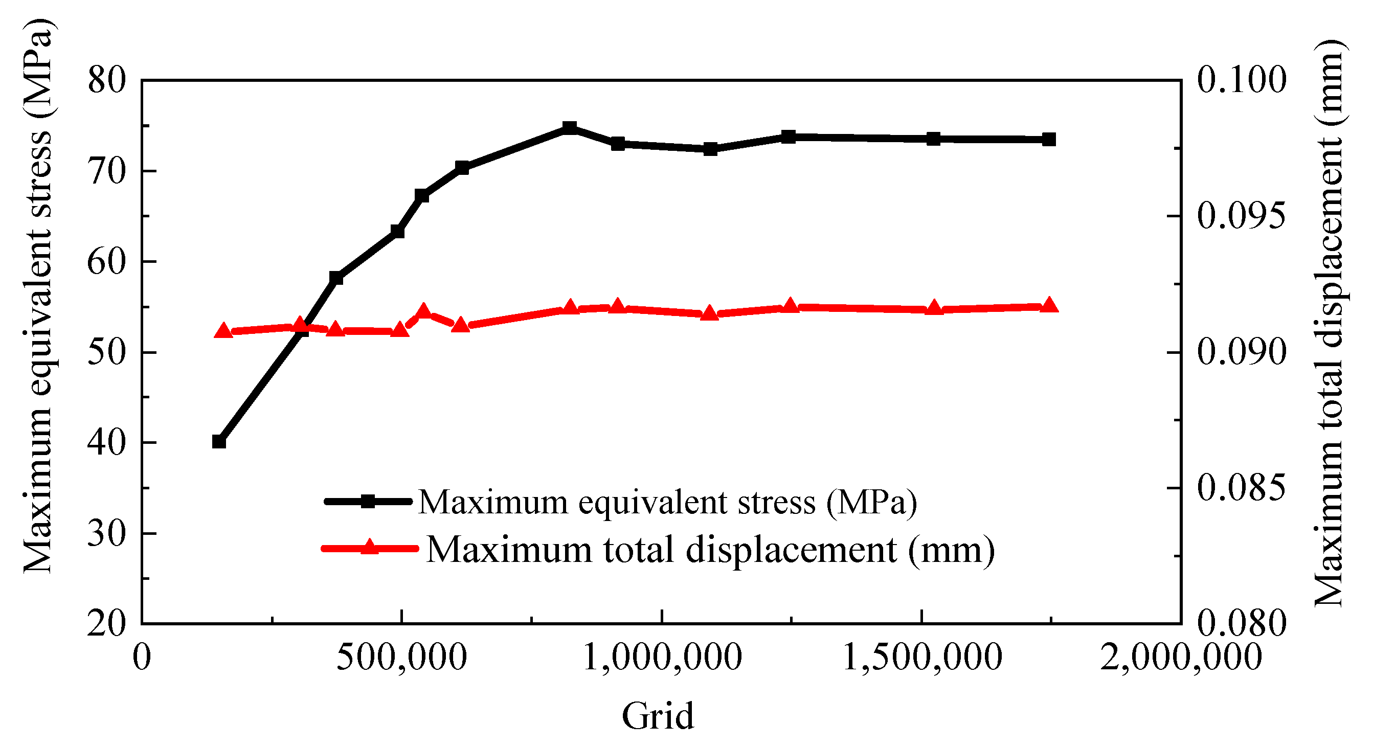
4.1. Computational Modeling and Meshing

The structural field calculation object is a separate centrifugal pump impeller, and the impeller material is martensitic mild steel (13Cr4Ni), the specific characteristics are displayed in Table 3. The impeller modeling is crucial in precisely simulating the transition between the blade and the impeller front and rear cover plate, since stress concentration frequently occurs in the blade root region. Additionally, the division of the regional mesh is encrypted to ensure precise representation, to avoid the calculation process due to the mesh division of the cause of the stress concentration phenomenon that should not occur. Due to the complex structure of the impeller, tetrahedral cells are used for meshing.
This work aims to mitigate the impact of mesh quantity on the structural field calculation of the impeller. To achieve this, the mesh division is conducted using varying numbers, and the static stress calculation of the impeller is carried out for a certain same working condition (Q = 900 m3/h). In order to facilitate observation, Figure 8 illustrates the relationship between the static stress and deformation values at various mesh counts. It is evident that the number of meshes employed in the impeller design has a negligible impact on the deformation. Additionally, the maximum equivalent stress variation stabilizes as the number of meshes reaches 1,600,000, and considering the computational efficiency, this research utilizes a mesh count of 1,600,000 to conduct computations and analyze static stresses on the impeller.

4.2. Boundary Conditions for Structural Field Calculations

Constraints: the displacement constraints are fixed impeller shaft hole end face. Fluid-structure interaction boundary: the part of the impeller in contact with the flow field. Load: mainly includes centrifugal force, gravity and water pressure on the blade surface. The impeller is a rotating part, which is realized by applying centrifugal force load to the impeller area. The applied z-axis direction gravity acceleration is 9.8 m/s2. The water pressure at the interface of the fluid-structure interaction is determined by analyzing the outcomes of the flow field computation.

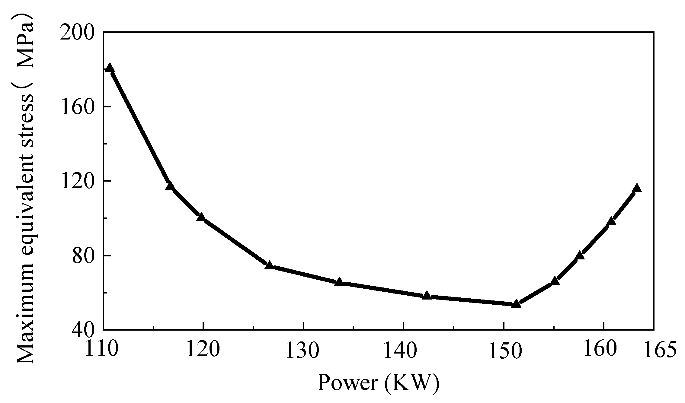
4.3. Calculated Field Results in Structures Analyzed

By solving the impeller with finite elements, Figure 9 illustrates the maximum equivalent stress and the maximum total deformation across several operational scenarios. With the climb of flow, the maximum stress value and the total deformation are first reduced and then gradually increased, and reached the minimum value near the design condition point, the maximum stress condition appeared at low flow rates, especially near the 0 flow condition, the equivalent force of the impeller reaches 181 MPa, about 3 times of the maximum equivalent force value of the design condition, analyze the reason, mostly attributed to the elevated head at modest flow rates. This leads to bigger pressure differentials on both the front and rear surfaces of the vane. Notably, the maximum deformation experienced is approximately three times greater than what was initially anticipated during the design phase, the primary reason for this phenomenon can be attributed to the fact that in low flow conditions, the centrifugal pump exhibits a higher head, resulting in a bigger pressure differential between the leading and trailing edges of the vane, which leads to the larger equivalent force on the impeller. In the vicinity of 0 flow condition, the total deformation also reaches the maximum value of 0.26 mm. The permissible stress of the impeller material is 560 MPa. The static stress of the centrifugal pump meets the requirements of the material.
The graphical representation in Figure 10 illustrates the correlation between the maximum equivalent force and the shaft power at each different operating condition. With the increase of shaft power, the observed trend in the maximum equivalent force exerted by the impeller exhibits a pattern of initial decrease followed by subsequent increase. After the design condition point, the maximum equivalent force of the impeller shows an approximately linear relationship with the power, which indicates that at this point, the maximum equivalent force is related to the torque.
Figure 11 and Figure 12 show the displacement and deformation distribution and equivalent force diagrams under three typical conditions, respectively. Through observation, the maximum deformations all occur at the outer edge of the back cover plate outlet, which is because the impeller has a lower stiffness here and the fluid pressure here is higher, and stiffness damage is easy to occur in these places. The impeller experiences its highest equivalent stresses at the curved corner where the intersection of the back exit edge of the blade and the front cover plate takes place, as shown in Figure 11. Here the blade outlet pressure is higher, and here the thickness is thin, and it is also the intersection round corner of the front cover plate and the blade, which makes it easy to produce stress concentration. Significant stress concentrations are seen near the midpoint of the intake side of the blade, as well as at the junction where the blade intersects with both the front and rear cover plates.

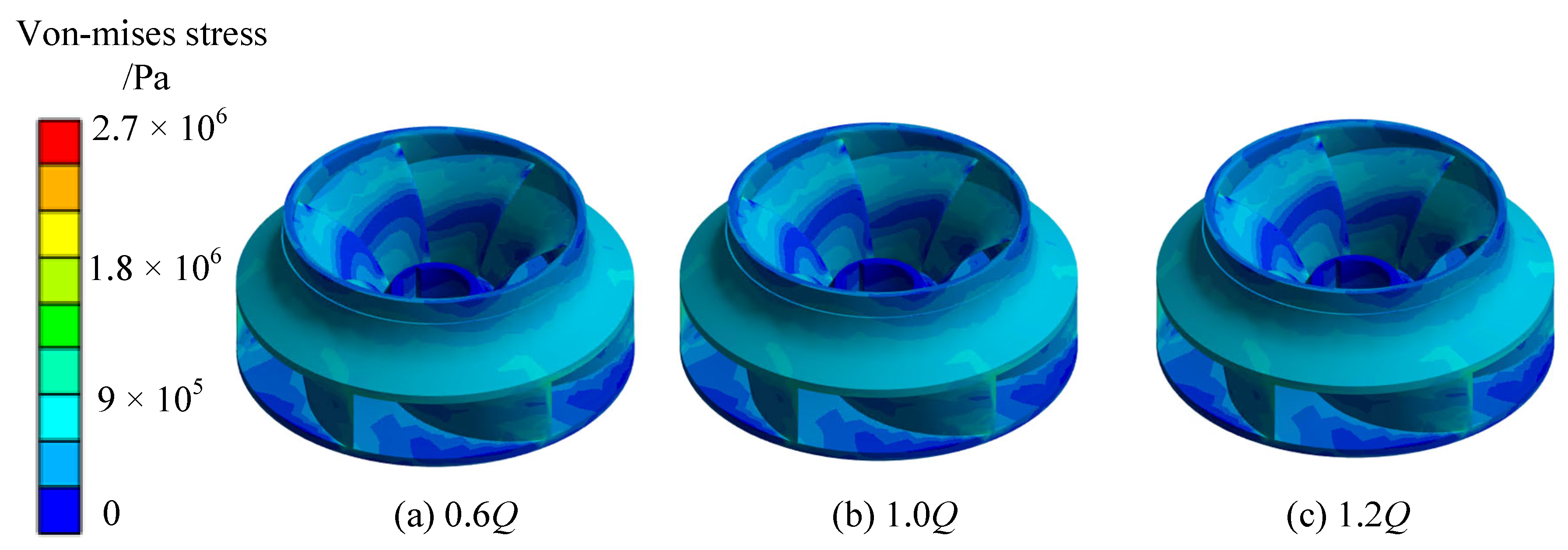
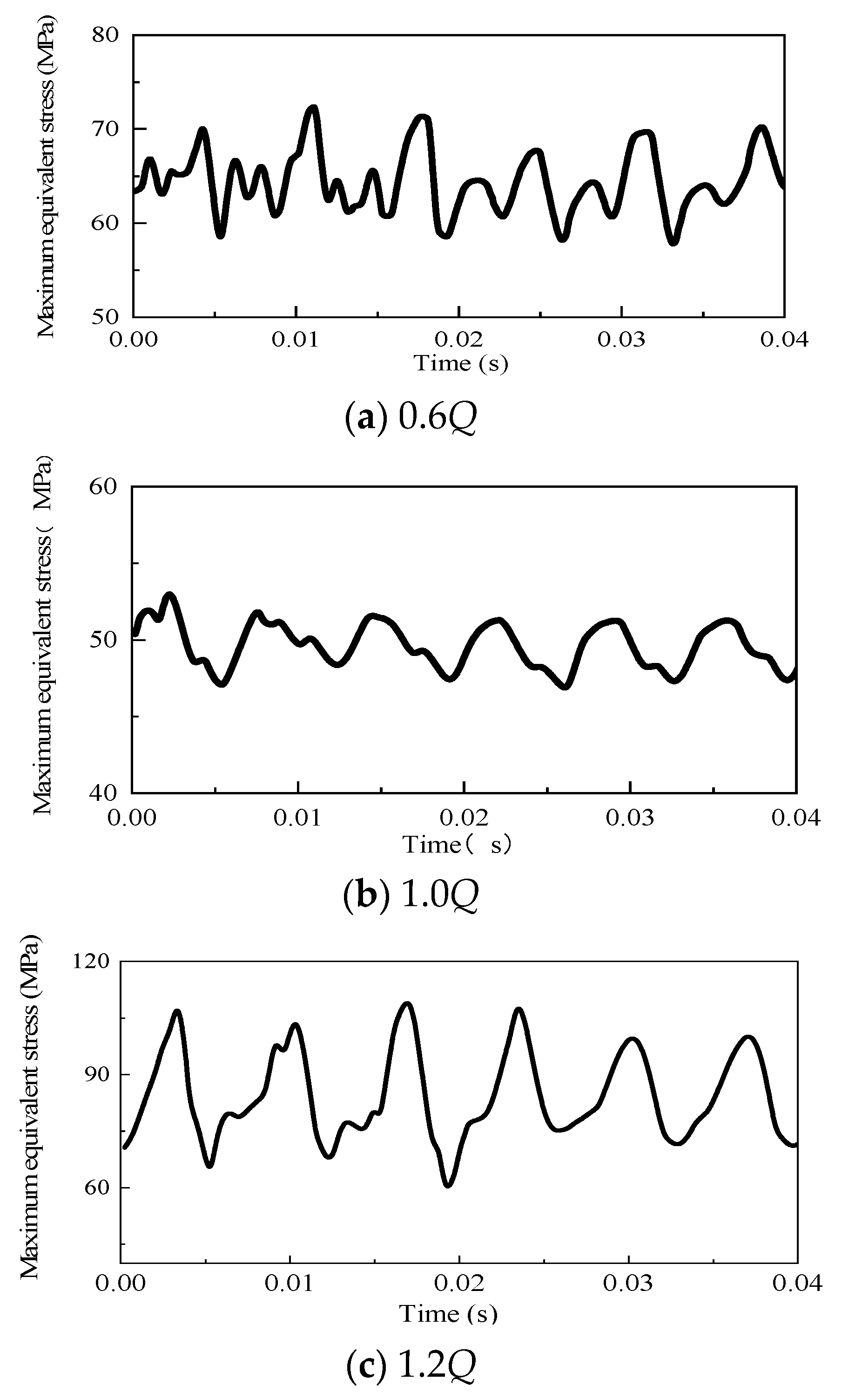
4.4. Stress Characterization of Impeller at Different Moments

The rated rotational speed of the centrifugal pump is n = 1450 r/min, and the rotational period is T = 0.04 s. To conduct an analysis of the stress experienced by the impeller at various time points throughout a rotational cycle, the structural field and the impeller field of the centrifugal pump are rotated sequentially by 5° until the end of the rotational period (360°), and, at the same time, the positional relationship between the vane and the tongue of the volute will likewise undergo alteration. The results of the rotated flow field are sequentially loaded into the corresponding impeller structure field, and the stresses of the impeller at different moments are calculated. Figure 13 illustrates the temporal distribution of the greatest equivalent stresses experienced by the impeller during three representative operational scenarios at different moments in one rotation cycle (T = 0.04 s). It can be seen that, under each condition, the stress experienced at the maximum stress point of the impeller during one rotation cycle exhibits a cyclic pattern, characterized by six peaks and valleys. This discovery is consistent with the relationship between the number of impeller blades and the frequency of maximum stress, indicating that both the number of impeller blades and the rotational speed have a significant influence on the frequency of maximum stress. Furthermore, it is evident that the maximum equivalent stress amplitude significantly increases when subjected to high flow rates. The periodic variations in the internal flow field characteristics of a centrifugal pump are caused by the dynamic and static interference between the impeller and the volute casing, as well as the changing relative positions of the impeller blades and the volute tongue. Consequently, these factors also impact the distribution of equivalent forces acting on the impeller. Although the maximum stress is very small compared with the ultimate destructive stress of the material, it is necessary to prevent the fatigue damage of the vane because its change shows periodicity.
Calculation results show that, as the flow rate increases, the impeller undergoes variations in both maximum equivalent stress and deformation. Initially, these values decrease and then increase, reaching their minimum near the design condition point. The impeller exhibits its highest stress and deformation levels under low flow conditions, particularly at zero flow where the maximum equivalent stress reaches 181 MPa and the maximum total deformation is 0.26 mm. To guarantee the secure and dependable operation of the pump and pumping station system, centrifugal pumps should be avoided to operate under 0–0.2 Q flow conditions. The impeller undergoes its most significant distortion at the exit of the rear cover plate. The maximum equivalent stress of the impeller occurs at the corner where the outlet edge of the back of the blade intersects with the front cover plate of the impeller. There is a significant stress concentration in the middle of the inlet edge of the blade and at the junction with the front and rear cover plates.
During a single rotation cycle, the stress experienced at the maximum stress point of the impeller exhibits periodic fluctuations, characterized by six peaks and valleys. This pattern aligns with the quantity of impeller blades, suggesting that the frequency of stress at the maximum stress point of the blade is primarily influenced by both the quantity of impeller blades and the rotational speed. Furthermore, under conditions of high flow rate, the maximum equivalent stress amplitude demonstrates a substantial increase. The primary reason for the cyclic variations in the internal flow characteristics of the centrifugal pump is the rotor-stator interference effect that occurs between the impeller and the volute. The alterations are determined by the relative positioning of the blade and the tongue of the volute. Consequently, the impact on the impeller’s equivalent stress distribution is likewise influenced. Despite the impeller’s maximum stress being significantly lower than the material’s ultimate destructive stress, it is imperative to mitigate fatigue damage to the blades due to the cyclic nature of stress fluctuations.

5. Conclusions

This study centers on an analysis of a large-scale centrifugal pump using the finite element method. The research adopts a one-way fluid-structure interaction approach to systematically evaluate the flow dynamics within the pump. Subsequently, this analysis facilitates the determination of the inherent modes of the impeller, both in air and water environments. Following this, a comprehensive static stress analysis of the impeller is conducted. The results of the calculations presented in this research unveil the following key insights:
The natural frequency of the impeller when submerged in water exhibits a noticeable reduction in comparison to its natural frequency in an air environment. This reduction varies across different modes, with higher-order modes experiencing a more pronounced decrease, suggesting a heightened impact of the surrounding medium on the intrinsic frequency of the impeller. A detailed examination of the first ten order displacement and vibration pattern diagrams of the impeller in both air and water reveals a similarity, with paired patterns evident in both environments. This observed symmetry stems from the impeller’s inherent periodic structural characteristics.
Structural stress field calculations reveal a pattern: as the flow rate increases, there is an initial decrease followed by a subsequent increase in both maximum equivalent stress and deformation. These values reach their minimum near the design condition point. Notably, the lowest flow condition, particularly at 0 flow, exhibits the highest levels of stress and deformation. At its peak, the maximum equivalent stress registers at 181 MPa, while the overall deformation reaches a maximum of 0.26 mm.
The most pronounced distortion occurs at the exit of the rear cover plate, with the maximum equivalent force on the impeller observed at the curved corner where the outlet side of the blade’s back meets the front cover plate of the impeller. Furthermore, there is a conspicuous concentration of stress both in the middle of the blade’s inlet side and at its junction with both the front and rear cover plates. The periodic alterations in the internal flow field characteristics of the centrifugal pump stem from the dynamic and static interference effects arising from the interaction between the impeller and the worm case. These variations are further influenced by the changing relative positions of the blade and the spacer’s tongue. Consequently, the maximum equivalent stress also exhibits periodic fluctuations.
In light of these findings, ensuring the secure and reliable operation of pumps and pumping station systems necessitates avoiding the utilization of centrifugal pumps under flow conditions falling within the range of 0 to 0.2 Q.

Author Contributions

Methodology, S.L.; Software, Y.T. and Y.L.; Validation, J.D. and M.D.; Writing—original draft, H.Y.; C.Y. (Changliang Ye); Supervision, C.Y. (Chunxia Yang) and Y.Z. All authors have read and agreed to the published version of the manuscript.

Funding

This research was funded by the National Natural Science Foundation of China (Grant number: 52209109, No.52271275, No.52379086) and the Scientific Research Start-up Funding, Hohai University (1047/423160).

Data Availability Statement

The data presented in this study are available on request from the corresponding author.

Conflicts of Interest

Author Siwei Li, Yongsha Tu and Mengfan Dang were employed by Hunan Water Resources and Hydropower Survey, Design, Planning and Research, Co., Ltd. Author Jin Dai and Yongbiao Li were employed by Hunan Provincial Water Resources Development and Investment Co., Ltd. The remaining authors declare that the research was conducted in the absence of any commercial or financial relationships that could be construed as a potential conflict of interest.

References

  1. Adams, R. What Constitutes’ High Energy’ In Centrifugal Pumps? In Proceedings of the 30th International Pump Users Symposium, Houston, TX, USA, 23–25 September 2014; Turbomachinery Laboratories, Texas A&M Engineering Experiment Station: College Station, TX, USA, 2014. [Google Scholar]
  2. Chan, E.Y.Y.; Ho, J.Y.E. Urban water and health issues in Hong Kong. In Urban Drought: Emerging Water Challenges in Asia; Springer Nature: Singapore, 2019; pp. 241–262. [Google Scholar]
  3. Roy, A.; Palit, P.; Das, S.; Mukhyopadyay, G. Investigation of torsional fatigue failure of a centrifugal pump shaft. Eng. Fail. Anal. 2020, 112, 104511. [Google Scholar] [CrossRef]
  4. Ye, C.; Tang, Y.; An, D.; Wang, F.; Zheng, Y.; van Esch, B.P.M. Investigation on stall characteristics of marine centrifugal pump considering transition effect. Ocean Eng. 2023, 280, 114823. [Google Scholar] [CrossRef]
  5. Huang, X.; Fang, T.; Pang, K.; Guo, Q.; Qiu, B.; Lu, J. Air-entrained vortex in open intake: Time–frequency analysis and the interaction with subsurface vortices. Phys. Fluids 2022, 34, 113313. [Google Scholar] [CrossRef]
  6. Zheng, L.; Chen, X.; Dou, H.-S.; Zhang, W.; Zhu, Z.; Cheng, X. Effects of clearance flow on the characteristics of centrifugal pump under low flow rate. J. Mech. Sci. Technol. 2020, 34, 189–200. [Google Scholar] [CrossRef]
  7. Hoseini, S.S.; Najafi, G.; Ghobadian, B.; Akbarzadeh, A.H. Impeller shape-optimization of stirred-tank reactor: CFD and fluid structure interaction analyses. Chem. Eng. J. 2021, 413, 127497. [Google Scholar] [CrossRef]
  8. Hirschhorn, M.; Tchantchaleishvili, V.; Stevens, R.; Rossano, J.; Throckmorton, A. Fluid–structure interaction modeling in cardiovascular medicine—A systematic review 2017–2019. Med. Eng. Phys. 2020, 78, 1–13. [Google Scholar] [CrossRef]
  9. Cuamatzi-Meléndez, R.; Flores-Cuamatzi, E. Modelling fluid-structure interaction of water recirculating flow to predict damage and/or failure in a jet-pump assembly of a nuclear boiling water reactor. Eng. Struct. 2020, 206, 110155. [Google Scholar] [CrossRef]
  10. De Donno, R.; Ghidoni, A.; Noventa, G.; Rebay, S. Shape optimization of the ERCOFTAC centrifugal pump impeller using open-source software. Optim. Eng. 2019, 20, 929–953. [Google Scholar] [CrossRef]
  11. Olimstad, G.; Østby, P.T.K. Failure and redesign of a high-speed pump with respect to rotor-stator interaction. Eng. Fail. Anal. 2019, 104, 704–713. [Google Scholar] [CrossRef]
  12. Wang, W.; Zhou, L.; Tao, R.; Song, X.; Wang, Z. Numerical simulation of dynamic characteristics of hydrofoil structure under cavitation conditions. Ocean Eng. 2023, 280, 114937. [Google Scholar] [CrossRef]
  13. Griffith, B.E.; Patankar, N.A. Immersed Methods for Fluid–Structure Interaction. Annu. Rev. Fluid Mech. 2020, 52, 421–448. [Google Scholar] [CrossRef] [PubMed]
  14. Mo, J.-O.; Lee, Y.-H. Performance Prediction and Flow Characteristics of a Hydraulic Pump for ABS and ESC Systems Using FSI Simulation. Int. J. Automot. Technol. 2020, 21, 1419–1429. [Google Scholar] [CrossRef]
  15. Ye, C.; Wang, C.; Yan, H.; Wang, F.; Zheng, Y.; van Esch, B.P.M. Investigation on transition characteristics of laminar separation bubble on a hydrofoil. Phys. Fluids 2023, 35, 105154. [Google Scholar] [CrossRef]
  16. Luo, H.; Zhou, P.; Shu, L.; Mou, J.; Zheng, H.; Jiang, C.; Wang, Y. Energy Performance Curves Prediction of Centrifugal Pumps Based on Constrained PSO-SVR Model. Energies 2022, 15, 3309. [Google Scholar] [CrossRef]
  17. Krzemianowski, Z.; Steller, J. High specific speed Francis turbine for small hydro purposes-Design methodology based on solving the inverse problem in fluid mechanics and the cavitation test experience. Renew. Energy 2021, 169, 1210–1228. [Google Scholar] [CrossRef]
  18. Krella, A.; Maurin, A.; Krzemianowski, Z. Degradation of Armco iron caused by cavitation: Part II—Correlation with stress analysis. Eng. Fail. Anal. 2021, 128, 105621. [Google Scholar] [CrossRef]
  19. He, L.; Zhou, L.; Ahn, S.-H.; Wang, Z.; Nakahara, Y.; Kurosawa, S. Evaluation of gap influence on the dynamic response behavior of pump-turbine runner. Eng. Comput. 2019, 36, 491–508. [Google Scholar] [CrossRef]
  20. Xia, X.; Zhou, L.; Lv, Y.; Wang, Z. Numerical investigation of two degree-of-freedom galloping oscillation of a cylinder attached with fixed fairing device. Ocean Eng. 2021, 240, 109971. [Google Scholar] [CrossRef]
  21. Yang, J.; Zhou, L.-J.; Wang, Z.-W.; Jiang, X.-Y.; Zhou, X.-J.; Ding, J.-H.; Han, W.-F. Numerical investigation of the cavitation dynamic parameters in a Francis turbine draft tube with columnar vortex rope. J. Hydrodyn. 2019, 31, 931–939. [Google Scholar] [CrossRef]
  22. Hübner, B.; Silva, D.R. Advanced simulation of coupled physics in thrust bearings. In IOP Conference Series: Earth and Environmental Science; IOP Publishing: Bristol, UK, 2019; Volume 240, p. 062009. [Google Scholar]
  23. Hübner, B.; Seidel, U.; Roth, S. Application of fluid-structure coupling to predict the dynamic behavior of turbine components. In IOP Conference Series: Earth and Environmental Science; IOP Publishing: Bristol, UK, 2010; Volume 12, p. 012009. [Google Scholar]
  24. Trivedi, C.; Cervantes, M.J. Fluid-structure interactions in Francis turbines: A perspective review. Renew. Sustain. Energy Rev. 2017, 68, 87–101. [Google Scholar] [CrossRef]
  25. Badshah, M.; Badshah, S.; Jan, S. Comparison of computational fluid dynamics and fluid structure interaction models for the performance prediction of tidal current turbines. J. Ocean Eng. Sci. 2020, 5, 164–172. [Google Scholar] [CrossRef]
  26. Zanetti, G.; Cavazzini, G.; Santolin, A. Effect of the von Karman Shedding Frequency on the Hydrodynamics of a Francis Turbine Operating at Nominal Load. Int. J. Turbomach. Propuls. Power 2023, 8, 27. [Google Scholar] [CrossRef]
  27. Kan, K.; Zheng, Y.; Fu, S.; Liu, H.; Yang, C.; Zhang, X. Dynamic stress of impeller blade of shaft extension tubular pump device based on bidirectional fluid-structure interaction. J. Mech. Sci. Technol. 2017, 31, 1561–1568. [Google Scholar] [CrossRef]
  28. Quan, H.; Cheng, J.; Guo, Y.; Kang, L.; Peng, G. Influence of Screw Centrifugal Inducer on Internal Flow Structure of Vortex Pump. J. Fluids Eng. 2020, 142, 091203. [Google Scholar] [CrossRef]
  29. Presas, A.; Valentin, D.; Zhao, W.; Egusquiza, M.; Valero, C.; Egusquiza, E. On the use of neural networks for dynamic stress prediction in Francis turbines by means of stationary sensors. Renew. Energy 2021, 170, 652–660. [Google Scholar] [CrossRef]
  30. Valentín, D.; Presas, A.; Valero, C.; Egusquiza, M.; Egusquiza, E.; Gomes, J.; Avellan, F. Transposition of the mechanical behavior from model to prototype of Francis turbines. Renew. Energy 2020, 152, 1011–1023. [Google Scholar] [CrossRef]
  31. Chen, X.; Lai, X.; Gou, Q.; Song, D. Effect of guide vane profile on the hydraulic performance of moderate low-specific-speed Francis turbine. J. Mech. Sci. Technol. 2023, 37, 1289–1300. [Google Scholar] [CrossRef]
  32. Menéndez -Blanco, A.; Oro, J.M.F.; Meana-Fernández, A. Unsteady three-dimensional modeling of the Flu-id-Structure Interaction in the check valves of diaphragm volumetric pumps. J. Fluids Struct. 2019, 90, 432–449. [Google Scholar] [CrossRef]
  33. Li, W.; Ji, L.; Shi, W.; Zhou, L.; Jiang, X.; Zhang, Y. Fluid-structure interaction study of a mixed-flow pump impeller during startup. Eng. Comput. 2018, 35, 18–34. [Google Scholar] [CrossRef]
  34. Birajdar, R.; Keste, A. Prediction of Flow-Induced Vibrations due to Impeller Hydraulic Unbalance in Vertical Turbine Pumps Using One-Way Fluid-Structure Interaction. J. Vib. Eng. Technol. 2020, 8, 417–430. [Google Scholar] [CrossRef]
  35. Shi, L.; Zhu, J.; Wang, L.; Chu, S.; Tang, F.; Jin, Y. Comparative Analysis of Strength and Modal Characteristics of a Full Tubular Pump and an Axial Flow Pump Impellers Based on Fluid-Structure Interaction. Energies 2021, 14, 6395. [Google Scholar] [CrossRef]
  36. Wang, H.; Wang, F.; Wang, B.; Wu, J.; Lu, H.; Wang, C. Partial flow separation in guide-vane region of large-capacity/low-head pumped hydro energy storage system with horizontal shaft. J. Energy Storage 2023, 71, 108173. [Google Scholar] [CrossRef]
  37. Ye, C.; An, D.; Huang, W.; Heng, Y.; Zheng, Y. Investigation on Stall Characteristics of Centrifugal Pump with Guide Vanes. Water 2023, 15, 21. [Google Scholar] [CrossRef]
  38. Yan, H.; Heng, Y.; Zheng, Y.; Tao, R.; Ye, C. Investigation on Pressure Fluctuation of the Impellers of a Double-Entry Two-Stage Double Suction Centrifugal Pump. Water 2022, 14, 4065. [Google Scholar] [CrossRef]
  39. Wang, C.; Wang, F.; Li, C.; Chen, W.; Wang, H.; Lu, L. Investigation on energy conversion instability of pump mode in hydro-pneumatic energy storage system. J. Energy Storage 2022, 53, 105079. [Google Scholar] [CrossRef]
  40. Zeng, Y.; Yao, Z.; Huang, B.; Wu, Q.; Wang, F. Experimental investigation of the hydrodynamic damping of a vibrating hydrofoil in cavitating flow. Ocean Eng. 2022, 266, 112734. [Google Scholar] [CrossRef]
  41. Tickoo, S. ANSYS Workbench 2021 R1: A Tutorial Approach; CADCIM Technologies: Schererville, IN, USA, 2021. [Google Scholar]
  42. Zhou, W.; Zhou, P.; Xiang, C.; Wang, Y.; Mou, J.; Cui, J. A Review of Bionic Structures in Control of Aerodynamic Noise of Centrifugal Fans. Energies 2023, 16, 4331. [Google Scholar] [CrossRef]
Figure 1. Computational domain. (a) Finite element model of impeller; (b) Fluid domain.
Water 15 04269 g001
Figure 2. Finite element model of impeller in water.
Water 15 04269 g002
Figure 3. Test rig.
Figure 3. Test rig.
Water 15 04269 g003
Figure 4. Comparison of energy characteristics.
Water 15 04269 g004
Figure 5. The natural frequencies of the impeller at different stages in air and water.
Water 15 04269 g005
Figure 6. Modal diagrams of each order of the impeller in air.
Water 15 04269 g006
Figure 7. Modal diagrams of each order of the impeller in water.
Water 15 04269 g007
Figure 8. Grid independence check.
Water 15 04269 g008
Figure 9. Maximum equivalent stress and maximum deformation under various operational situations.
Water 15 04269 g009
Figure 10. Maximum equivalent force of impeller vs. shaft power of centrifugal pumps.
Water 15 04269 g010
Figure 11. Distribution of impeller displacement and deformation.
Water 15 04269 g011
Figure 12. Equivalent force distribution of impeller.
Water 15 04269 g012
Figure 13. Time-domain diagram of stress at the maximum stress point.
Water 15 04269 g013
Table 1. Material properties and meshing of impeller.
ParametersValue
Modulus of elasticity E (Gpa)206
Poisson ratio μ0.288
Material density ρ (kg/m3)7700
Meshing8-node tetrahedral solid unit solid 45
Table 2. Comparison of impeller intrinsic frequencies of each order in air and water.
Mode Orderƒa (Hz)ƒw (Hz)η = ƒw/ƒa
1767.54352.840.46
2768.19354.420.46
3917.33354.430.39
41105.8477.610.43
51259.2573.660.46
61260.6574.010.46
71696.7591.560.35
81704.7591.560.35
91708.9604.960.35
101747.3695.880.40
Table 3. Physical parameters of impeller materials.
Physical QuantityMeasure ValuePhysical QuantityMeasure Value
Density ρ (kg/m3)7700Tensile strength σb (MPa)580
Modulus of elasticity E (GPa)206Yield limit σs (MPa)950
Poisson’s ratio μ0.288Permissible stress [σ], (MPa)560
Disclaimer/Publisher’s Note: The statements, opinions and data contained in all publications are solely those of the individual author(s) and contributor(s) and not of MDPI and/or the editor(s). MDPI and/or the editor(s) disclaim responsibility for any injury to people or property resulting from any ideas, methods, instructions or products referred to in the content.

