
Pressure Pulsation Characteristics of Agricultural Irrigation Pumps under Cavitation Conditions

Abstract
:1. Introduction
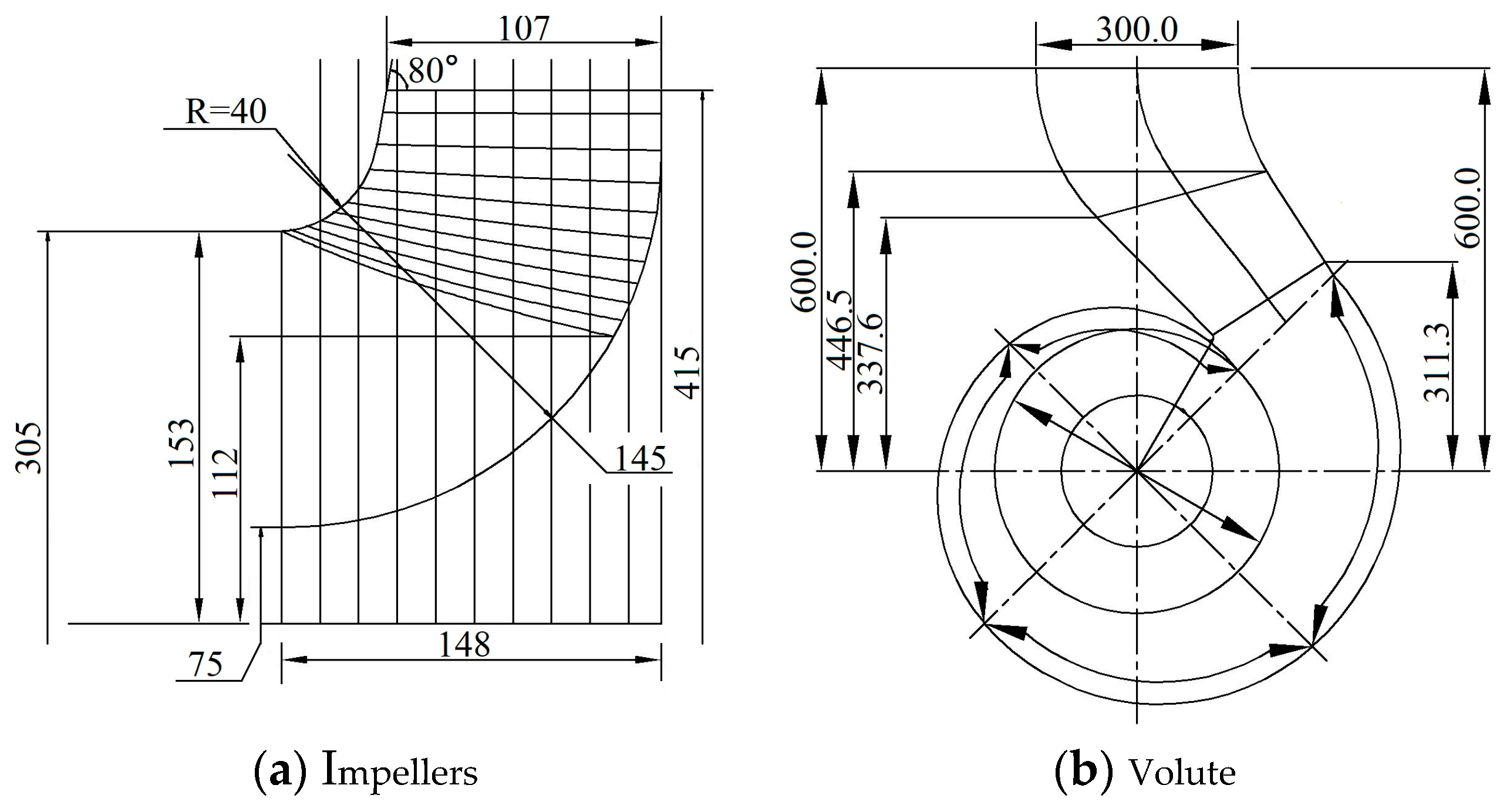
2. Model Parameters
2.1. Three-Dimensional Modeling
2.2. Cavitation Model
3. Numerical Calculation
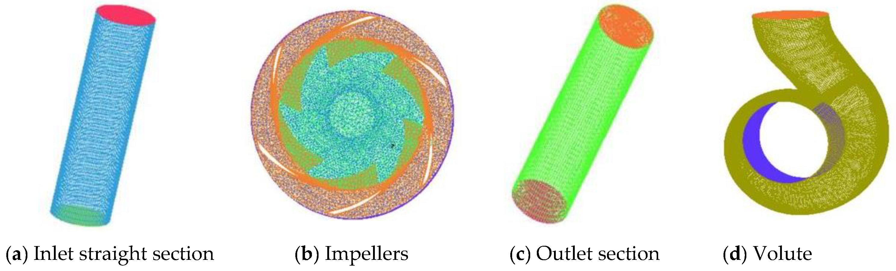
3.1. Models and Meshes
3.2. Boundary Condition
4. Experimental Verification
5. Pressure Pulsation Analysis of Pumps with Different Numbers of Vanes
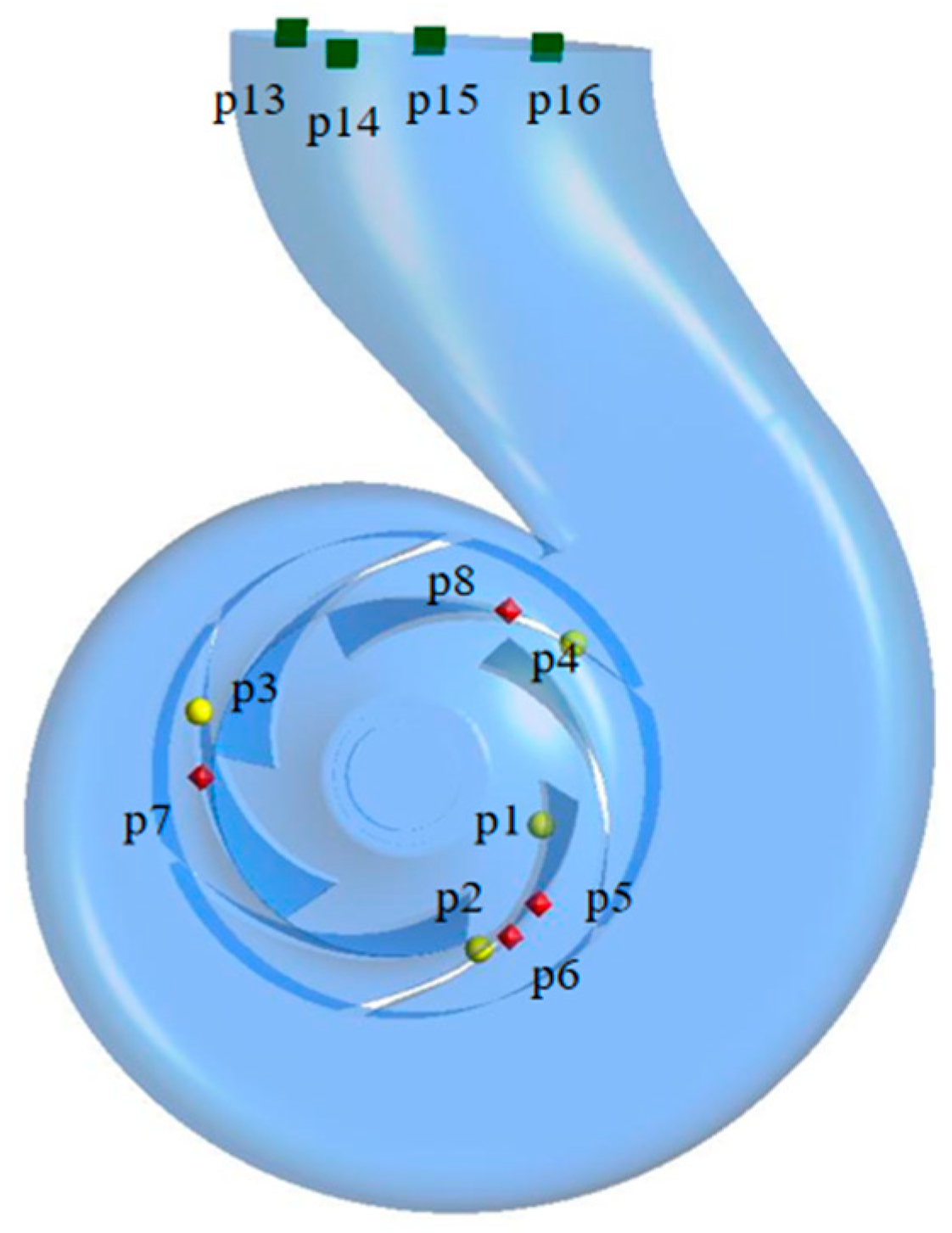
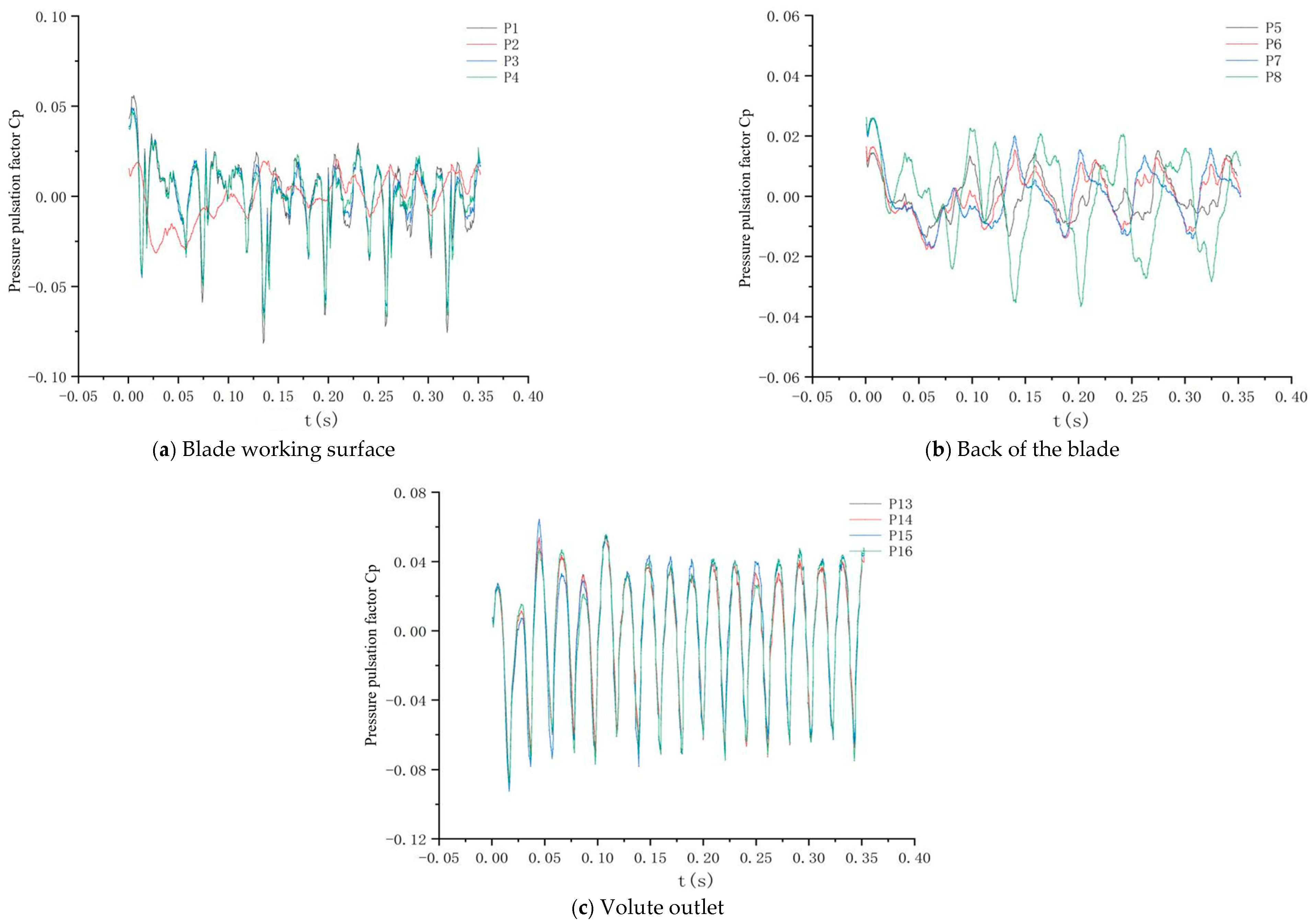
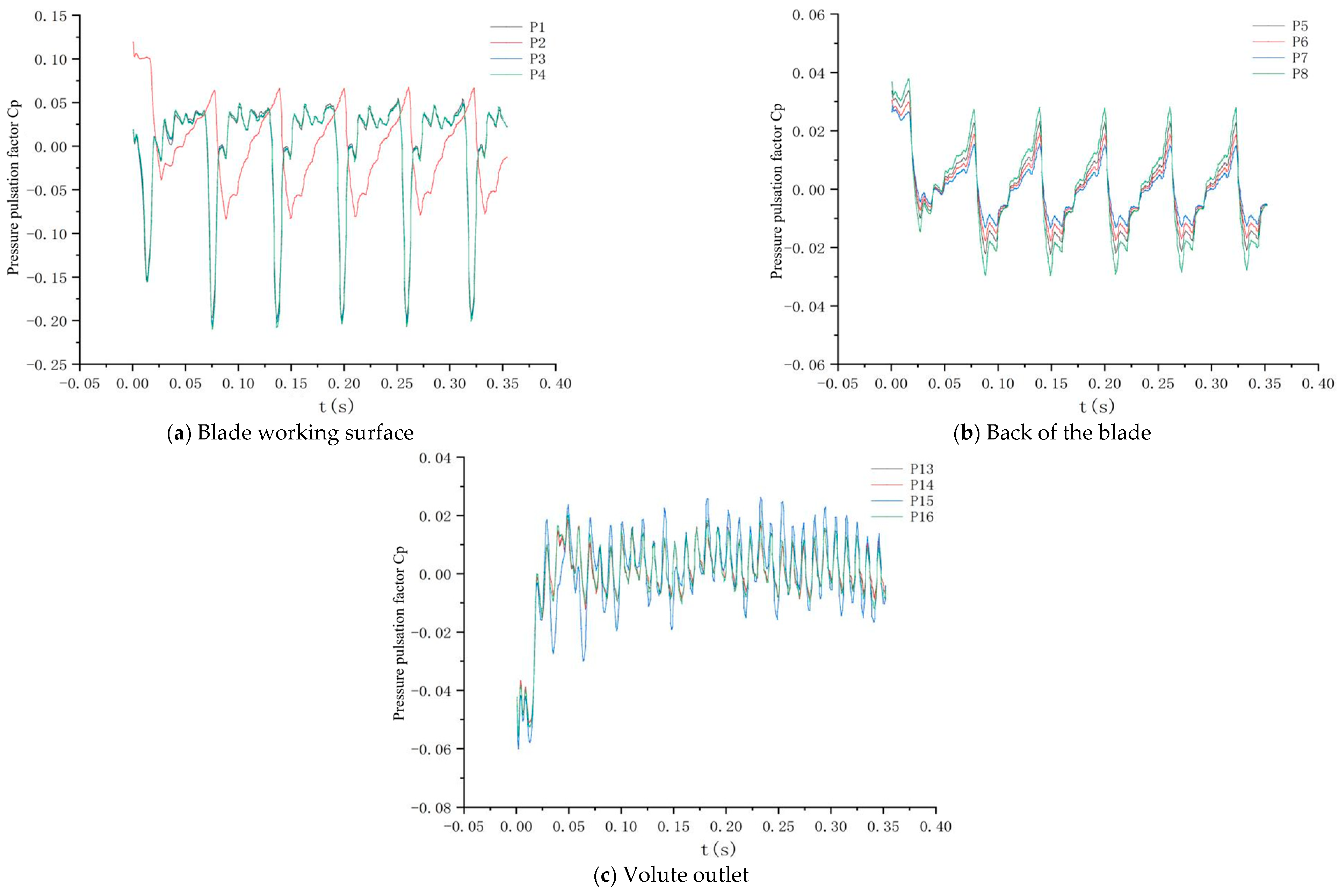
5.1. Time-Domain Characterization of Pressure Pulsations
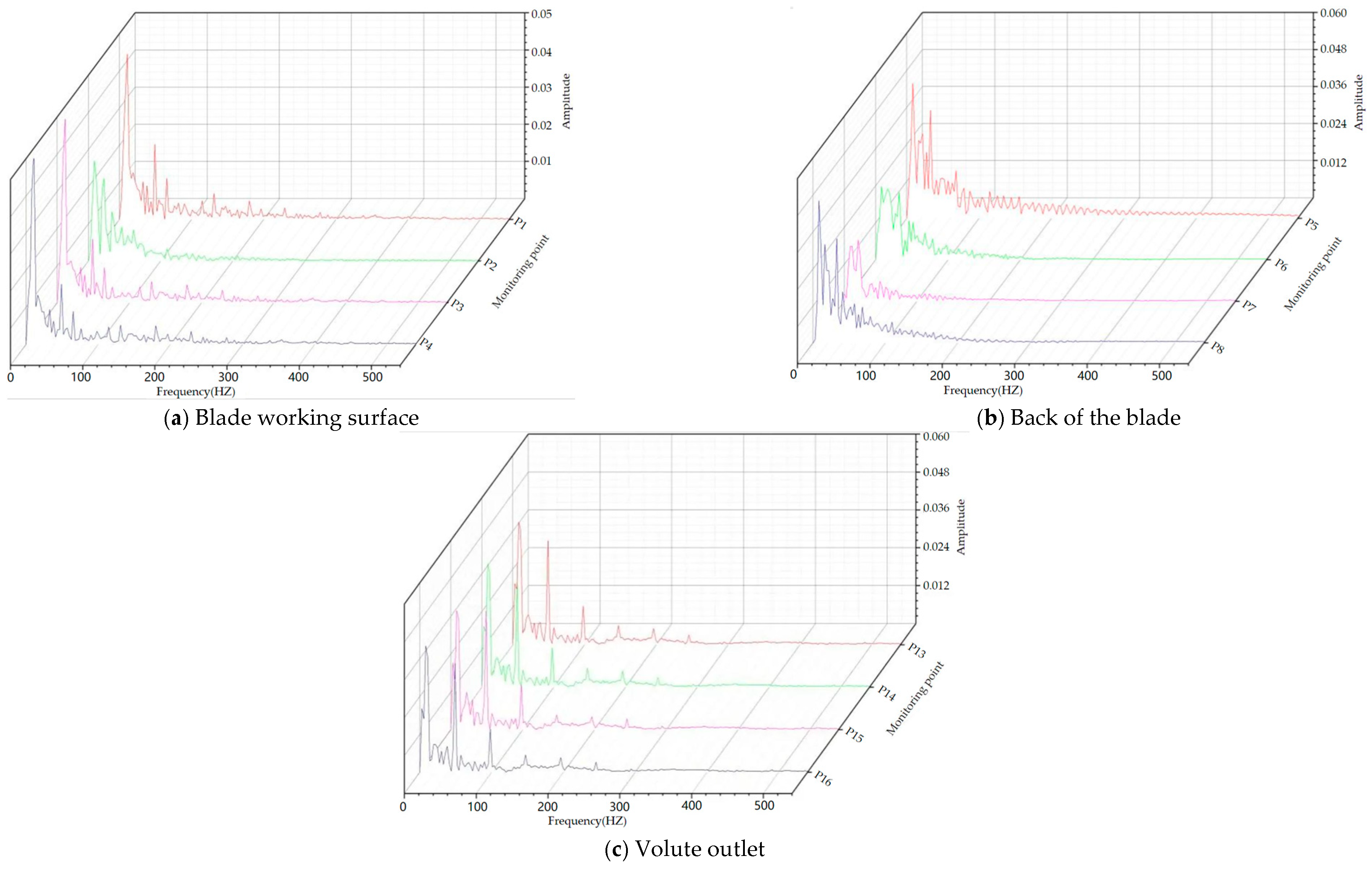
5.2. Pressure Pulsation Frequency Domain Characterization
6. Analysis of Pump Pressure Pulsation under Cavitation Conditions
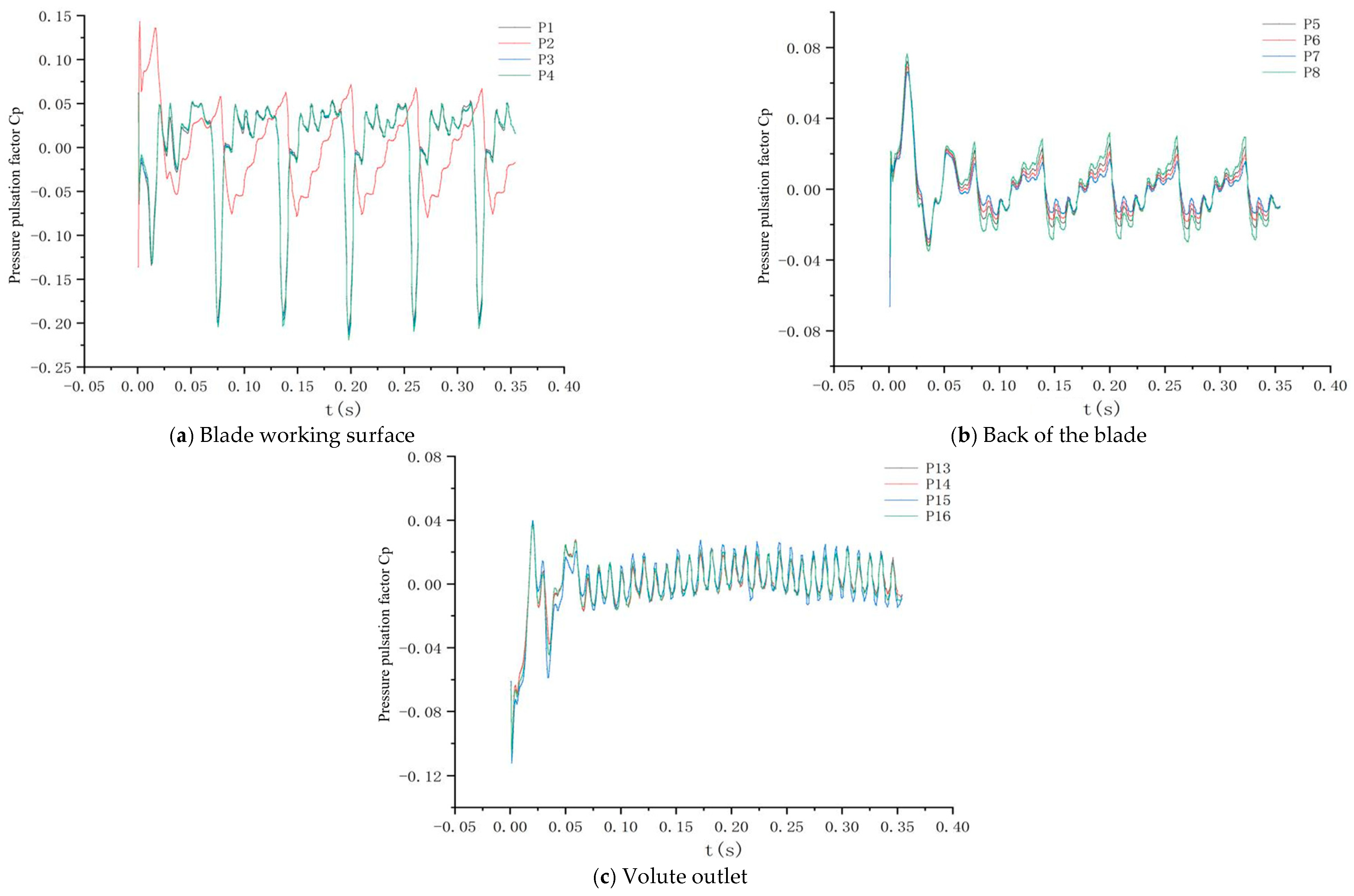
6.1. Time-Domain Characterization of a Pump under Cavitation Conditions
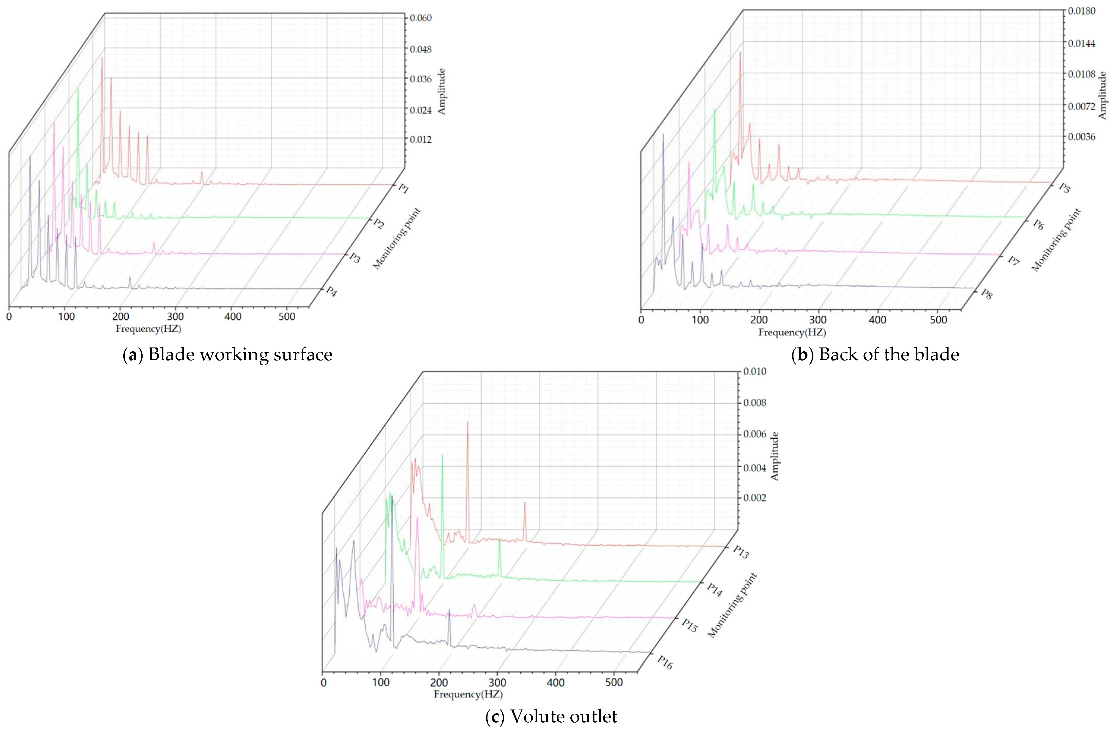
6.2. Frequency Domain Characterization of Pumps under Cavitation Conditions
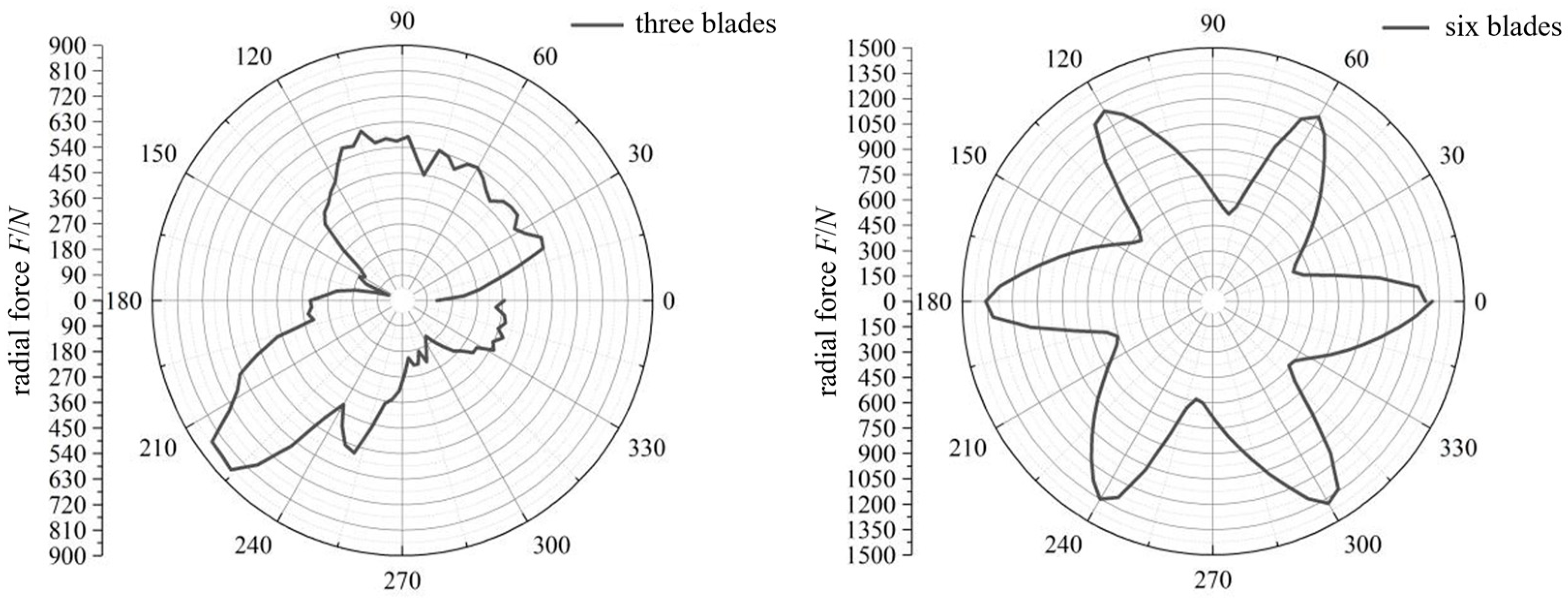
7. Radial Force Analysis
8. Conclusions
- (1)
- Under the head and efficiency test, data were obtained through pump performance tests and the values were compared with the numerical simulation results. The results show that the data have small errors under the design conditions, indicating that the numerical simulation in this article has a certain level of reliability.
- (2)
- Under non-cavitating conditions, the pressure fluctuations at monitoring points on the working surface, back surface, and volute exit of impellers with different blade numbers show periodic variations and are related to the number of blades. The pressure fluctuation on the working surface is greater than that on the back surface. The pressure fluctuation of the six-bladed impeller is more uniform than that of the three-bladed impeller, and the internal flow is more stable. Under cavitation conditions, the pressure pulsation coefficients increase compared to the non-cavitating conditions, but the pressure fluctuations are affected by cavitation, which it’s uncertain. The pressure fluctuations at monitoring points on the three-bladed impeller are more complex and do not show obvious periodicity, while the overall trend of the six-bladed impeller changes less.
- (3)
- The frequency of pressure pulsation in the impeller is a multiple of its rotational frequency. Under non-cavitating conditions, the amplitude of the pressure pulsation on the working surface of the six-bladed impeller is larger than that of the three-bladed impeller at the same frequency. The pressure fluctuation at the volute exit is more complex, while the variations in other monitoring areas are not significant. Under cavitation conditions, the overall trend of the three-bladed and six-bladed impellers remains consistent with the non-cavitating conditions. The amplitude of the pressure pulsation at the same frequency on the three-bladed impeller is larger than that under non-cavitating conditions, while the increase in amplitude at monitoring points on the six-bladed impeller is slight.
- (4)
- By analyzing the unsteady characteristics of the radial force of centrifugal pumps with different impeller blade numbers during high-speed operation, it is found that, under constant flow rate conditions, the radial force on the impeller is significantly influenced by the number of blades, with the six-bladed impeller experiencing higher radial forces than the three-bladed impeller. Under cavitation conditions, the number of impeller blades and the distribution of radial forces are mutually influenced by the cavitation effect.
Author Contributions
Funding
Data Availability Statement
Acknowledgments
Conflicts of Interest
References
- Choi, Y.D.; Kurokawa, J.; Matsui, J. Performance and internal flow characteristics of a very low specific speed centrifugal pump. J. Fluids Eng. 2006, 128, 341–349. [Google Scholar] [CrossRef]
- Wang, C.; Yao, Y.; Yang, Y.; Chen, X.; Wang, H.; Ge, J.; Cao, W.; Zhang, Q. Automatic optimization of centrifugal pump for energy conservation and efficiency enhancement based on response surface methodology and computational fluid dynamics. Appl. Comput. Fluid Mech. 2023, 17, 2227686. [Google Scholar] [CrossRef]
- Skrzypacz, J.; Bieganowski, M. The influence of micro grooves on the parameters of the centrifugal pump impeller. Int. J. Mech. Sci. 2018, 144, 827–835. [Google Scholar] [CrossRef]
- Yu, H.; Wang, C.; Li, G.; Wang, H.; Yang, Y.; Wu, S.; Cao, W.; Li, S. Steady and unsteady flow characteristics inside short jet self-priming pump. Sustainability 2023, 15, 13643. [Google Scholar] [CrossRef]
- Mi, H.; Wang, C.; Jia, X.; Hu, B.; Wang, H.; Wang, H.; Zhu, Y. Hydraulic characteristics of continuous submerged jet impinging on a wall by using numerical simulation and PIV experiment. Sustainability 2023, 15, 5159. [Google Scholar] [CrossRef]
- Qiu, N.; Zhu, H.; Xu, P.; Che, B.; Wu, J.; Zhou, W.; Wang, C. Assessment of cavitation erosion risk indicated by pressure impact exceeding material strength threshold. Phys. Fluids 2023, 35, 093307. [Google Scholar] [CrossRef]
- Yang, J.; Zhang, X.; Li, H.; Li, Y. The influence of draft tube guide plate on the inner flow of centrifugal pump as turbine. Hydraul. Pneum. Seals 2021, 41, 56–60+63. [Google Scholar]
- Yuan, S.Q.; He, W.T.; Si, Q.R.; Yuan, J.P.; Zhang, H.Y.; Cui, Q.L. Numerical simulation on gas-liquid two-phase flow in centrifugal pump based on MUSIG model. J. Drain. Irrig. Mach. Eng. 2021, 39, 325–330+337. [Google Scholar]
- Shen, Z.; Chu, W. Influence of grooves arrangement in volute casing on internal flow characteristics of centrifugal pump. J. Huazhong Univ. Sci. Technol. (Nat. Sci. Ed.) 2019, 47, 37–42. [Google Scholar]
- Lu, J.L.; Guo, P.C.; Wang, L.K.; Liao, W.L.; Zhao, X.H. lnfluence of impeller clocking on the inner flow of a two-stage centrifugal pump. J. Xi’an Univ. Technol. 2019, 35, 300–307. [Google Scholar]
- Si, Q.; Cui, Q.; Yuan, J.; Zhang, K.; Yuan, Q. Tests for flow induced characteristics of a centrifugal pump under air-water two-phase inflow condition. J. Vib. Shock 2019, 38, 15–21. [Google Scholar]
- Wang, W.; Wang, Y.; Li, Y.; Lu, R.; Liu, M. Internal flow diagnosis of centrifugal pumps based on vortex dynamics. China Rural. Water Hydropower 2019, 172–177. [Google Scholar]
- Lin, P.; Xu, W. Numerical study of influence of inlet ribs on steady flow of centrifugal pump. J. Zhejiang Sci-Tech Univ. (Nat. Sci. Ed.) 2019, 41, 461–465. [Google Scholar]
- Wu, S.; Wu, Y.; Tian, J.; Ouyang, H. On the cavitation-induced collapse erosion of a turbofan fuel pump. Eng. Appl. Comput. Fluid Mech. 2022, 16, 1048–1063. [Google Scholar] [CrossRef]
- Gu, Y.; Hao, S.; Wang, C.; Lu, R.; Liu, B.; Jie, G. Effect of trimmed rear shroud on performance and axial thrust of multi-stage centrifugal pump with emphasis on visualizing flow losses. J. Fluids Eng. 2024, 146, 011204. [Google Scholar] [CrossRef]
- Hu, B.; Yao, Y.; Wang, M.; Wang, C.; Liu, Y. Flow and performance of the disk cavity of a marine gas turbine at varying nozzle pressure and low rotation speeds: A numerical investigation. Machines 2023, 11, 68. [Google Scholar] [CrossRef]
- Xi, B.; Wang, C.; Xi, W.; Liu, Y.; Wang, H.; Yang, Y. Experimental investigation on the water hammer characteristic of stalling fluid in eccentric casing-tubing annulus. Energy 2022, 253, 124113. [Google Scholar] [CrossRef]
- Zhang, F.; Lu, Z.; Tao, R.; Wu, Y.; Li, P.; Xiao, R.; Liu, W.; Wang, F. Detection of the invisible blade pressure-side cavitation in pump impeller based on acoustic measurement and numerical prediction. Ann. Nucl. Energy 2022, 176, 109284. [Google Scholar] [CrossRef]
- Hu, J.B.; Xue, R.Y.; Liu, H.L.; Wang, K.; Lu, X. Hydraulic optimization and experimental measurement of low specific speed centrifugal fire pump. J. Appl. Fluid Mech. 2022, 15, 1477–1489. [Google Scholar]
- Kim, Y.I.; Yang, H.M.; Lee, K.Y.; Choi, Y.S. Numerical investigation on blockage-related cavitation surge and pressure gain of a mixed-flow pump with influence of blade leading edge shape on suction performance. J. Fluids 2022, 144, 091205. [Google Scholar] [CrossRef]
- Chen, B.; Zhang, H.; Wang, Y.; Ch, X. Cavitation characteristics of high-speed submersible axial-flow pump. J. Drain. Irrig. Mach. Eng. 2021, 39, 109–115. [Google Scholar]
- Bai, Y.; Feng, Z.; Wu, J.; Kong, F.; Chen, R. Experiment of thrust disk as auxiliary impeller in a high-speed rescue pump. J. Drain. Irrig. Mach. Eng. 2021, 39, 784–789. [Google Scholar]
- Gong, X.; Cao, P.; Wang, Y.; Zhu, R.; Wang, Y. Linear control design and internal flow analysis of diffuser trailing edge based on CFD. J. Drain. Irrig. Mach. Eng. 2021, 39, 1210–1217. [Google Scholar]
- Kan, K.; Zhang, Q.; Huang, J.; Li, H.; Zheng, Y.; Chen, L. Turbulence characteristics over a tubular pump using immersed boundary method based large-eddy simulation. J. Drain. Irrig. Mach. Eng. 2022, 40, 144–149. [Google Scholar]
- Lang, T.; Jin, L.; Liu, Y.; Chen, K.; Xu, E. Numerical analysis of hydrodynamic noise characteristics of single-blade centrifugal pump. J. Drain. Irrig. Mach. Eng. 2022, 40, 541–548. [Google Scholar]
- Xu, M.; Chen, S.; Yang, S.; Zhang, J.; Wang, J. Investigation on wicket gate closure law considering servomotor characteristics. J. Drain. Irrig. Mach. Eng. 2022, 40, 563–569. [Google Scholar]
- Yang, C.; Xia, Y. A novel two-step strategy of non-probabilistic multi-objective optimization for load-dependent sensor placement with interval uncertainties. Mech. Syst. Signal Process. 2022, 176, 109173. [Google Scholar] [CrossRef]
- Li, L.; Tan, Y.; Xu, W.; Ni, Y.; Yang, J.; Tan, D. Fluid-induced transport dynamics and vibration patterns of multiphase vortex in the critical transition states. Int. J. Mech. Sci. 2023, 252, 108376. [Google Scholar] [CrossRef]
- Bu, W.J.; Pan, S.C. Analysis of flow field and pressure pulsation in mixed-flow hydraulic turbine under partial load condition. J. Drain. Irrig. Mach. Eng. 2023, 41, 906–912. [Google Scholar]
- Ni, J.; Li, G.; Zheng, J.; Deng, L.; Wang, X. Optimization study of movable guide vane for reducing pressure pulsation in lobe-free zone of variable speed pump turbine. Hydropower Pumped Storage 2023, 9, 1–9+19. [Google Scholar]
- Wang, H.; Li, L.; Mou, C.; Zhou, P.; Wu, D. Analysis of transient cavitation flow and pressure pulsation of guide vane centrifugal pump. J. Metrol. 2023, 44, 931–938. [Google Scholar]
- Zheng, Z.; Ma, X.; Yan, Z.; Lu, C. Study on the pressure characteristics in jet influence zone riser. J. Chem. Eng. 2023, 74, 2335–2350+2242. [Google Scholar]
- Lord Rayleigh, O.M.F.R.S. VIII. On the pressure developed in a liquid during the collapse of a spherical cavity. Lond. Edinb. Dublin Philos. Mag. J. Sci. 1917, 34, 94–98. [Google Scholar] [CrossRef]
- Zhao, W.; Liu, M.; Liu, Y.; Sheng, J.; Song, Q. Effects of blade thickness on performance of low-specific-speed centrifugal pump. J. Drain. Irrig. Mach. Eng. 2015, 33, 1033–1037. [Google Scholar]
- Plesset, M.S.; Chapman, R.B. Collapse of an initially spherical vapour cavity in the neighbourhood of a solid boundary. J. Fluid Mech. 1971, 47, 283–290. [Google Scholar] [CrossRef]
- Cole, R.H. Underwater Explosions; Princeton University Press: Princeton, NJ, USA, 1948. [Google Scholar]
- Noltingk, B.E.; Neppiras, E.A. Cavitation produced by ultrasonics. Proc. Phys. Soc. 2002, 63, 674. [Google Scholar] [CrossRef]
- Singhal, A.K.; Athavale, M.M.; Li, H.; Jiang, Y. Mathematical basis and validation of the full cavitation model. J. Fluids Eng. 2002, 124, 617–624. [Google Scholar] [CrossRef]
- Zwart, P.; Gerber, A.G.; Belamri, T. A two-phase model for predicting cavitation dynamics. In Proceedings of the ICMF 2004 International Conference on Multiphase Flow, Yokohama, Japan, 30 May–4 June 2004; pp. 1–11. [Google Scholar]
- Habil, S.I. Physical and Numerical Modeling of Unsteady Cavitation Dynamics. In Proceedings of the ICMF 2001 International Conference on Multiphase Flow, New Orleans, LA, USA, 27 May–1 June 2001. [Google Scholar]
- Kunz, R.F.; Boger, D.A.; Stinebring, D.R.; Chyczewski, T.S.; Lindau, J.W.; Gibeling, H.J.; Venkateswaran, S.; Govindan, T.R. A preconditioned Navier–Stokes method for two phase flows with application to cavitation prediction. Comput. Fluids 2013, 29, 849–875. [Google Scholar] [CrossRef]
- Shi, W.; Xu, L.; Wang, C.; Lu, W.; Zhou, L. Numerical calculation and analysis of inner unsteady flow for volute centrifugal pump. Trans. Chin. Soc. Agric. Mach. 2014, 45, 49–53. [Google Scholar]
- Wang, Y.; Tan, L.; Cao, S.; Zhu, B. Characteristics of transient flow and pressure fluctuation in impeller for centrifugal pump. J. Mech. Eng. 2014, 50, 163–169. [Google Scholar] [CrossRef]


| Flow Parts | Impeller | Guide Vane | Inlet Section | Export Section |
|---|---|---|---|---|
| Grid number | 469,873 | 554,281 | 1,250,810 | 67,000 |
| Flow (m3/h) | Head (m) | ||
|---|---|---|---|
| CFD | Experimental | Relative Deviation (%) | |
| 800 | 17.30 | 16.90 | 2.36 |
| 1000 | 15.95 | 15.70 | 1.59 |
| 1100 | 15.10 | 14.50 | 4.13 |
| 1200 | 13.60 | 13.00 | 4.61 |
| 1300 | 11.63 | 11.30 | 2.92 |
| 1400 | 10.15 | 9.80 | 3.57 |
| Flow (m3/h) | Efficiency (m) | ||
|---|---|---|---|
| CFD | Experimental | Relative Deviation (%) | |
| 800 | 73.50 | 72.50 | 1.37 |
| 1000 | 77.10 | 76.00 | 1.44 |
| 1100 | 75.00 | 73.80 | 1.62 |
| 1200 | 73.80 | 72.30 | 2.07 |
| 1300 | 70.60 | 68.20 | 3.51 |
| 1400 | 67.80 | 64.90 | 4.46 |
| Flow (m3/h) | Head (m) | ||
|---|---|---|---|
| CFD | Experimental | Relative Deviation (%) | |
| 800 | 21.11 | 20.50 | 2.97 |
| 1000 | 19.60 | 19.40 | 1.03 |
| 1100 | 17.45 | 17.10 | 2.04 |
| 1200 | 16.50 | 16.45 | 0.30 |
| 1300 | 15.83 | 15.20 | 4.14 |
| 1400 | 12.50 | 12.00 | 4.16 |
| Flow (m3/h) | Efficiency (m) | ||
|---|---|---|---|
| CFD | Experimental | Relative Deviation (%) | |
| 800 | 74.50 | 72.98 | 2.08 |
| 1000 | 75.80 | 75.01 | 1.05 |
| 1100 | 74.04 | 72.93 | 1.52 |
| 1200 | 73.80 | 71.50 | 3.21 |
| 1300 | 72.60 | 71.15 | 2.03 |
| 1400 | 64.00 | 61.50 | 4.06 |
Disclaimer/Publisher’s Note: The statements, opinions and data contained in all publications are solely those of the individual author(s) and contributor(s) and not of MDPI and/or the editor(s). MDPI and/or the editor(s) disclaim responsibility for any injury to people or property resulting from any ideas, methods, instructions or products referred to in the content. |
© 2023 by the authors. Licensee MDPI, Basel, Switzerland. This article is an open access article distributed under the terms and conditions of the Creative Commons Attribution (CC BY) license (https://creativecommons.org/licenses/by/4.0/).
Share and Cite
Yu, G.; Li, G.; Wang, C. Pressure Pulsation Characteristics of Agricultural Irrigation Pumps under Cavitation Conditions. Water 2023, 15, 4250. https://doi.org/10.3390/w15244250
Yu G, Li G, Wang C. Pressure Pulsation Characteristics of Agricultural Irrigation Pumps under Cavitation Conditions. Water. 2023; 15(24):4250. https://doi.org/10.3390/w15244250
Chicago/Turabian StyleYu, Guisheng, Guohui Li, and Chuan Wang. 2023. "Pressure Pulsation Characteristics of Agricultural Irrigation Pumps under Cavitation Conditions" Water 15, no. 24: 4250. https://doi.org/10.3390/w15244250