1. Introduction
The rapid advancement of industry presents novel challenges and opportunities in various disciplines, such as semiconductors, integrated circuits, laser technologies, and more. The progress within these sectors potentially offers us highly integrated systems and miniaturized components or electronic devices. From a heat-transfer perspective, this developmental trajectory engenders an increase in the thermal flux density of systems, thereby leading to the generation of hot spots [
1,
2]. The reliability of electronic components is extraordinarily sensitive to operating temperatures, with research indicating that for every degree Celsius above the limit, the reliability of the component reduces by 5%. Consequently, to guarantee the performance of electronic systems and minimize the incidence of malfunctions, numerous scholars have concentrated their efforts on enhancing the system’s cooling performance to eliminate thermal loads and prevent the emergence of hot spots [
3,
4]. Regarding cooling technologies, numerous advanced methods have emerged thus far, including micro heat pipes, jet impingement cooling, and ion wind cooling, to name a few [
5]. In the 1980s, an innovative electronic cooling system—the microchannel heat sink—was proposed by Tuckerman and Pease. This heat sink demonstrated extraordinary cooling capabilities and, compared to other technologies, was cost-effective and also facilitated efficient heat dissipation [
6]. From that point onwards, scholars have conducted extensive research on various types of microchannel heat sinks.
Unquestionably, microchannel heat sinks have found applications in numerous studies. For instance, Alihosseini et al. [
7] proposed a PCR reaction device based on microchannel cooling. The study findings reveal that in such a device, cooling a saliva sample within the PCR wells requires merely 16.5 s, significantly reducing the time for DNA amplification while also occupying minimal space. Liu et al. [
8] proposed a novel dendritic microchannel heat sink for cooling a single prismatic lithium battery. The performance of the lithium battery with the dendritic microchannel heat sink was studied both numerically and experimentally. Optimal geometric parameters were obtained through single-objective and multi-objective genetic algorithm optimizations based on numerical research results. The results demonstrate that the optimized structure possesses efficient heat dissipation performance, with the maximum temperature of the lithium battery only reaching 306.84 K. Lan et al. [
9] proposed an aluminum microchannel cooling system, applying it to the study of temperature rise in a single prismatic lithium-ion battery under various discharge rates. The research findings corroborate that the microchannel cooling system can be employed in battery thermal management. This system is capable of reducing both the maximum temperature rise and the temperature disparity throughout the battery. Radwan et al. [
10] proposed a microchannel heat sink filled with nanofluids for cooling concentrated photovoltaic systems. They established a comprehensive model including a thermal model of the photovoltaic layer and a thermal fluid dynamics model of two-phase flow in the microchannel heat sink, to estimate performance parameters through numerical simulation. The study findings indicate that this heat sink not only significantly reduces the temperature of the solar cells but also retains high electrical efficiency, thereby enhancing the overall efficiency of the system. Chen et al. [
11] developed a temperature-equalizing plate (VC) with radial multi-arterial incursions into microchannels for the thermal management of high-power light-emitting diodes (LEDs). Experimental results reveal that, compared with traditional copper plates, the VC significantly enhances cooling capacity, reducing the substrate surface temperature of the LED module by 7–27%. The aforementioned studies demonstrate the substantial application value of microchannel heat sinks; thus, it is imperative to study microchannel radiators.
Pertaining to the heat sink channels themselves, it is indisputable that different channel shapes (including cross-sectional shapes and surface indentations or protrusions) yield distinct performance. Mohammed et al. [
12] conducted a numerical study on the heat transfer and flow characteristics of a wavy microchannel heat sink. The results demonstrate that the heat-transfer performance of the wavy microchannel surpasses that of a straight microchannel with an identical cross-section. The pressure-drop loss in the wavy microchannel is considerably less than the enhancement achieved in heat transfer. Lin et al. [
13] implemented improvements in the wavelength and amplitude of a wavy-channel heat sink. The study results indicate that the performance of the heat sink significantly improves when the wavelength of the wave unit decreases and the amplitude increases; the enhancement effect is even more pronounced when the absolute difference in wavelength or amplitude between two adjacent wave units increases. Mohammed et al. [
14] studied the impact of different channel shapes, such as serrated, curved, and stepped microchannels, on the performance of heat sinks. The research results indicate that the serrated heat sink has the minimum temperature and the maximum heat-transfer coefficient. The pressure-drop loss of all channel shapes is higher than that of traditional straight heat sinks. The serrated heat sink has the maximum pressure drop, friction coefficient, and wall shear-stress values, followed by the curved and stepped shapes. Chai et al. [
15] examined the fluid flow and heat-transfer characteristics of a microchannel heat sink with offset sectoral re-entrant cavities in the side walls. The research results show that the new heat sink enhances heat-transfer performance within an acceptable pressure drop. Lei Chai et al. [
16] investigated the enhanced heat transfer of a microchannel heat sink with periodic expansion–contraction cross-sections using experimental and numerical methods. The research findings suggest that, compared with traditional straight-channel heat sinks, the newly proposed heat sink with periodic expansion–contraction cross-sections significantly enhances heat-transfer capability, increasing the average Nusselt number by approximately 1.8 times.
Furthermore, it has been discovered that introducing some fins into the channel can enhance the performance of the heat sink. Li et al. [
17] designed a double-layer pin-fin heat sink structure and analyzed the impact of geometric effects on thermodynamic performance. The results suggest that among pin-fin structures with circular, diamond, and rectangular cross-sections, the circular pin-fin displays the best overall performance and minimal thermal resistance. Li et al. [
18] proposed a novel microchannel heat sink with triangular cavities and rectangular ribs (TC-RR) and examined the effects of relative rib width (α) and relative cavity width (β) on flow and heat-transfer performance. The research findings show that the thermal enhancement factor of the TC-RR microchannel with α = 0.3 and β = 2.24 reaches 1.69 at Re = 500. Due to a more uniform base temperature, reduced irreversibility, and superior heat-transfer performance, the novel micro heat sink holds promising prospects in microelectronic cooling systems. Pan et al. [
19] proposed a pin-fin staggered bifurcated microchannel (PFSMMC) heat sink. They analyzed the effects of the aspect ratio of the staggered distributor on the heat-transfer characteristics of the PFSMMC heat sink under various non-uniform heat source conditions. The results indicate that as the aspect ratio increases, the uniformity of the heated surface temperature decreases, but when the aspect ratio is 0.32, the maximum heated surface temperature is relatively lower. Feng et al. [
20] designed a novel interrupted microchannel with dual circular pin fins (IMCDCP) in each microchamber. The analysis of geometric parameters demonstrates that the spacing between pin fins plays a crucial role in wall temperature uniformity, and an appropriate pin-fin height contributes to enhanced heat transfer and reduced pressure drop. Alihosseini et al. [
21] designed a wavy microchannel heat sink with oblique slot fins, investigating the impact on the thermal performance of fins with a width of 250 and 125 μm. Furthermore, they studied the effect of spacing on heat transfer. The results show that the introduction of fins generated secondary flow, leading to the reformation of the thermal boundary layer at each fin location, thereby continuously shaping fluid flow. Mohamed Omri et al. [
22] performed a three-dimensional numerical analysis of nanofluid-enhanced heat transfer in a micro heat exchanger with triangular fins. Modification of the heat-exchanger geometry in the z-direction was carried out to achieve a uniform wall temperature profile. It was found that the performance of the heat exchanger can be significantly improved by using CNT nanofluids and triangular fins. However, the thermal performance factor increases with the increase in CNT volume fraction and decreases with the height of the fins.
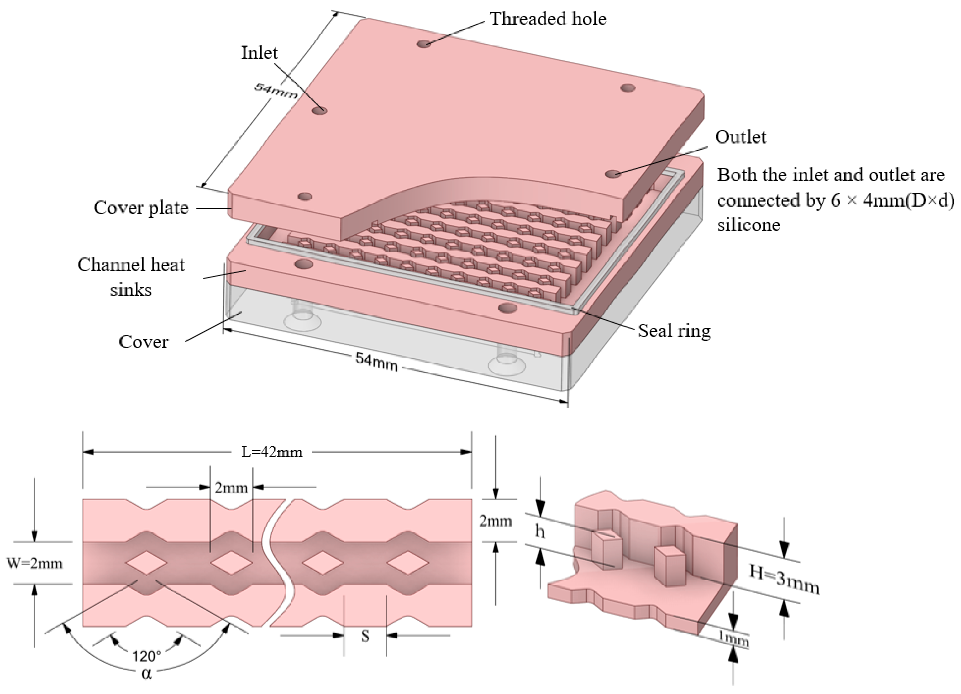
The above literature shows that the application of heat sinks is extremely wide, and their own geometric structures (including channel inserts) directly affect their performance. Therefore, it is very important to conduct geometric parameter research on heat sinks. Under specific conditions, a set or several sets of optimal parameters can be conveniently found through parameter research. These conditions can be a combination of one or several factors such as the uniformity of the base temperature of the heat sink, low overall fluid resistance in the channel, light weight, etc. Parameter analysis can also clearly reveal how geometric parameters affect the performance of the heat sink. In this article, a numerical study was conducted on a heat sink with diamond-shaped fins in the channel. The results under different Reynolds numbers were evaluated, and the effects of fin height, fin spacing, and the ratio of fin height to channel height were discussed in detail.
3. Experimental Device
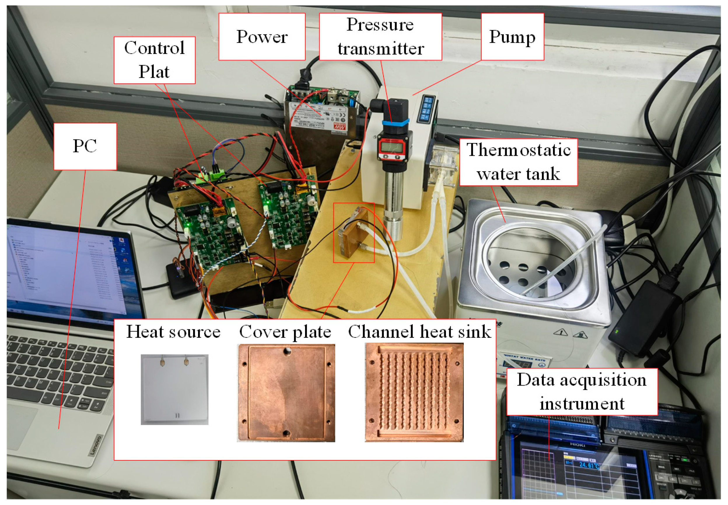
As illustrated in
Figure 3, the experimental setup comprises a direct current power source, a pump, a water bath, a data acquisition system, a pressure transducer, a control panel, a personal computer, an integrated heat sink, and a thermocouple assembly. The cover plate and channel heat sink are crafted from copper preforms in a single operation, thus negating the need for additional process treatments. A ceramic heating plate supplants traditional heating elements at the base of the radiator.
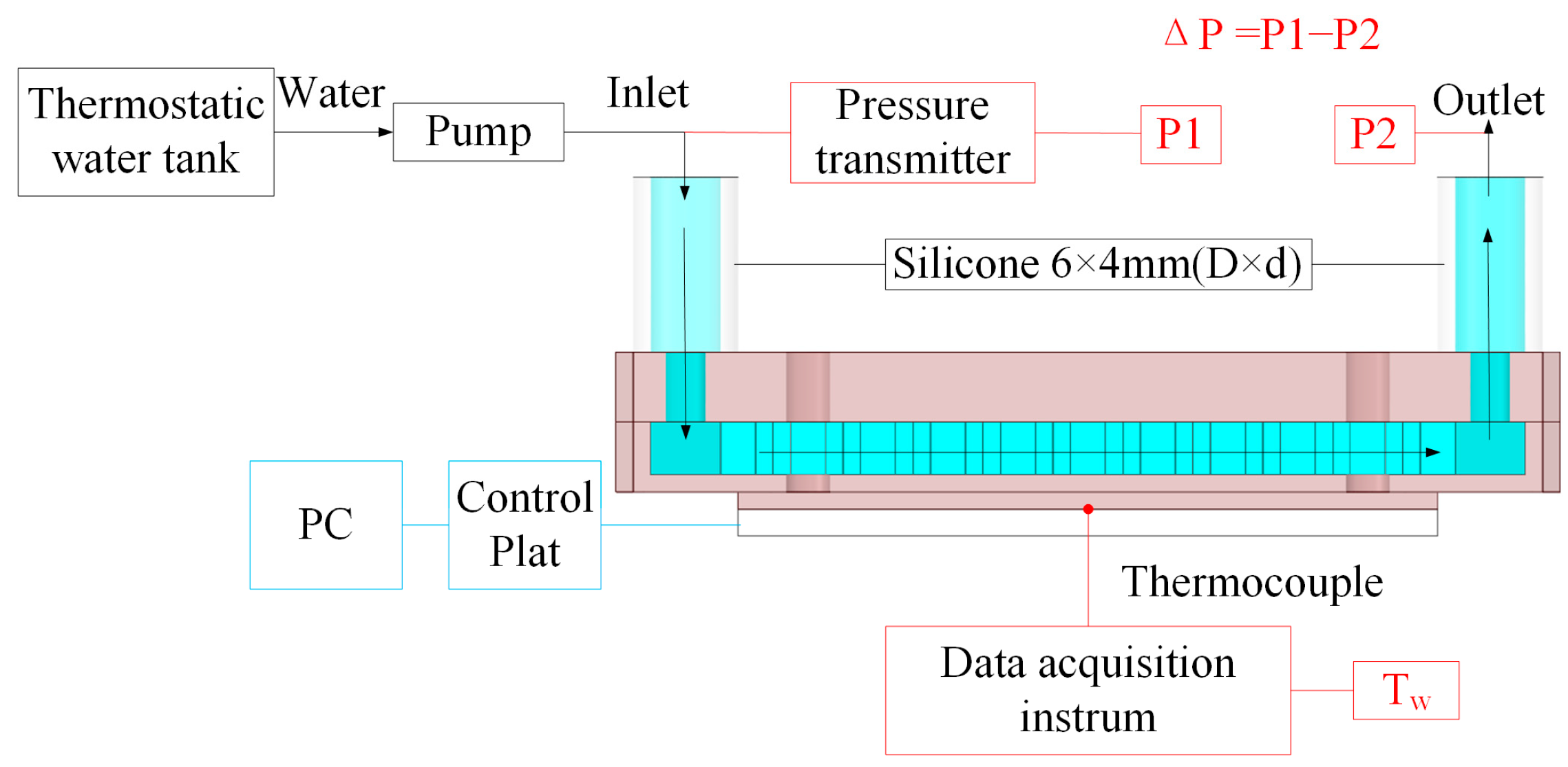
As depicted in
Figure 4, the computer, via the control plate, manages the power of the ceramic heating plate to emulate the heat generation of electronic devices. The interstice between the ceramic heating plate and the base surface is filled with thermal grease, mitigating the thermal resistance of component interconnections. A thermocouple, embedded within the central base surface of the channel heat sink and connected to the data acquisition system, procures the central base surface temperature, T
w. Water is introduced into the inlet of the channel heat sink through the operation of the pump, with its temperature maintained at an ideal ambient temperature (299.15 K) via the water bath. The inlet pressure P1 is acquired through a pressure transducer connection, while the outlet pressure P2 is at atmospheric levels. The overall pressure differential ΔP across the heat sink is determined by the subtraction of P2 from P1.
The uncertainty in this work primarily stems from the precision of the machined parts, sensor accuracy, and instrument resolution. Errors predominantly comprise the thermocouple’s uncertainty, part machining precision, pressure transmitter’s resolution, data acquisition system’s sampling accuracy, water bath’s precision, and the direct current power supply’s uncertainty. According to the studies of Pan et al. [
27] and Taylor et al. [
28], while each uncertainty in this study is small, the employment of multiple parameters in calculations may instigate the propagation of uncertainty. The method of calculating error propagation is given by:
where Y is the calculated quantity, Xi is the actual measured value, and E
Xi is the uncertainty of the actual measured value. The values of the uncertainty are exhibited in
Table 1.
4. Result and Discussion
The influence of structural parameters on radiator performance is investigated through three-dimensional simulation. The total inlet Reynolds number is utilized as the abscissa, while the Nusselt number Nu, thermal resistance R
t, apparent friction factor f, and heat-transfer enhancement factor η
f are employed as output data. The range of variables is summarized in
Table 2. Before analyzing the channel radiator’s performance, validation is required, including the accuracy of the simulation and grid independence.
The computation is performed on a 6-core processor (CPU: Intel i5-10500 3.10 Ghz 6 cores 12 threads, RAM: 16 GB DDR4 2400 Mhz). The solving method employs the pressure-based SIMPLE algorithm, with pressure, momentum, and energy using a second-order upwind scheme. Convergence is considered achieved when the continuity and velocity residuals are less than 1 × 10
−3, and the energy residual is less than 1 × 10
−6. The physical parameters of materials are listed in
Table 3.
4.1. Validation
4.1.1. Validation of Grid Independence
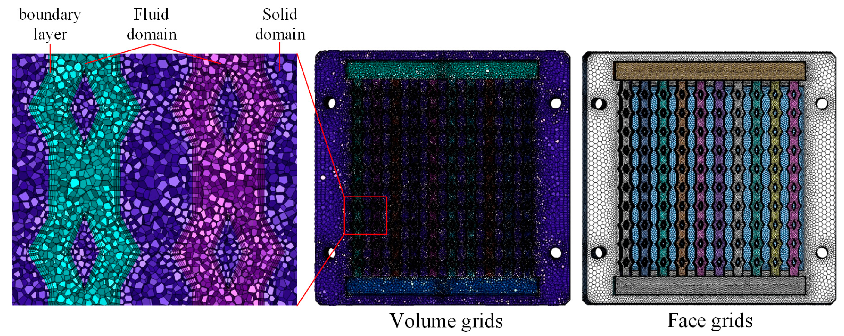
As illustrated in
Figure 5, polyhedral mesh division is carried out using Fluent. Mesh independence verification is performed on the flow-channel heat sink with s = 2 mm, α = 90°, and β = 100% (inlet flow rate of 120 mL·min
−1, water temperature of 299.15 K). The verification indices for mesh independence are the average temperature of the base surface (
) and the pressure difference between the inlet and outlet of Channel 5 (
).
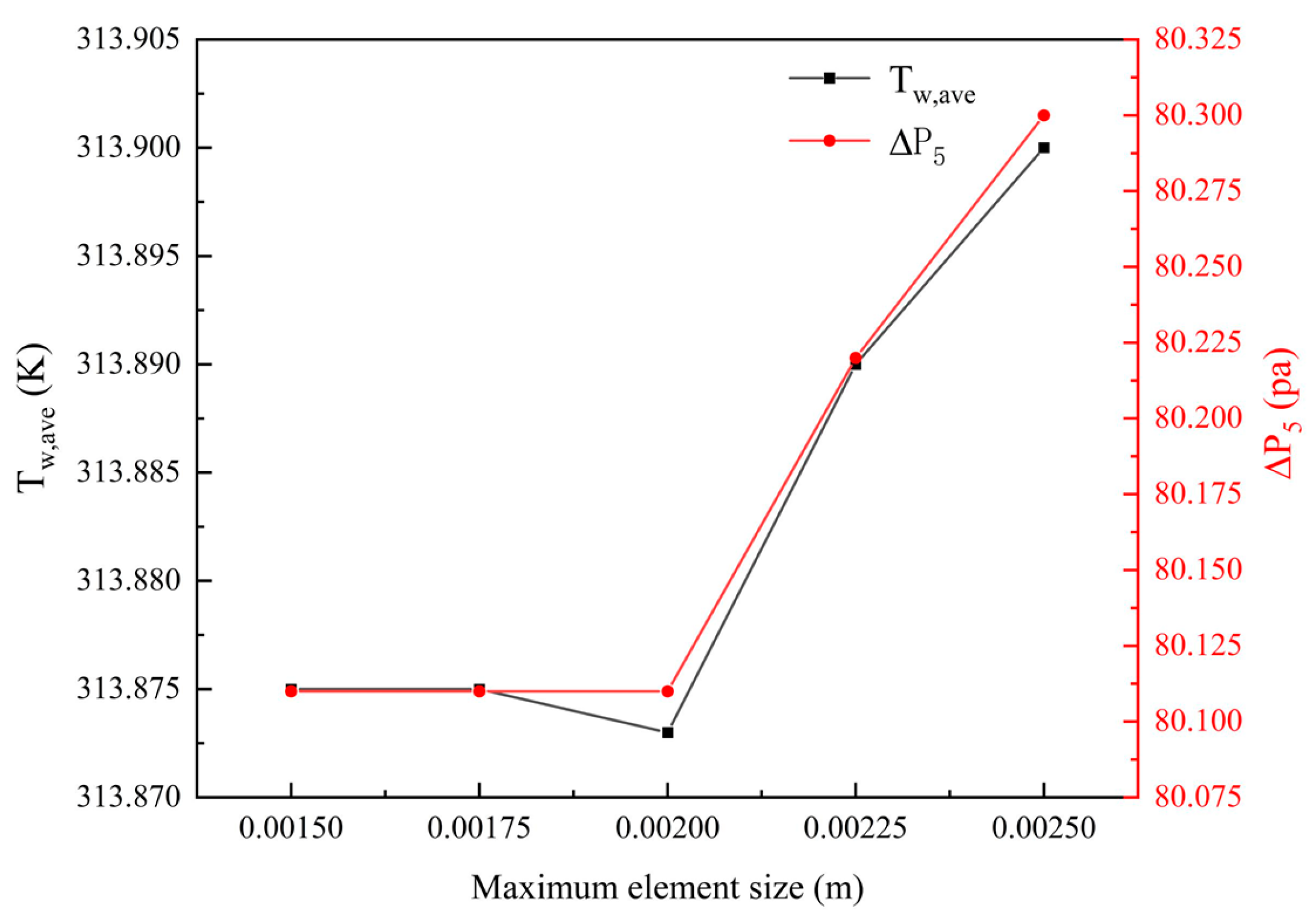
As shown in
Figure 6,
and
decrease with the reduction of the maximum element size, stabilizing when the mesh size is less than 0.00225 m. Subsequently, as the mesh is refined, the deviations in
and
are both less than 5%. This agrees with the grid independence. After comprehensive consideration of simulation accuracy and calculation time, the maximum mesh size of 0.002 m was utilized for subsequent simulation research.
4.1.2. Validation of Numerical Model
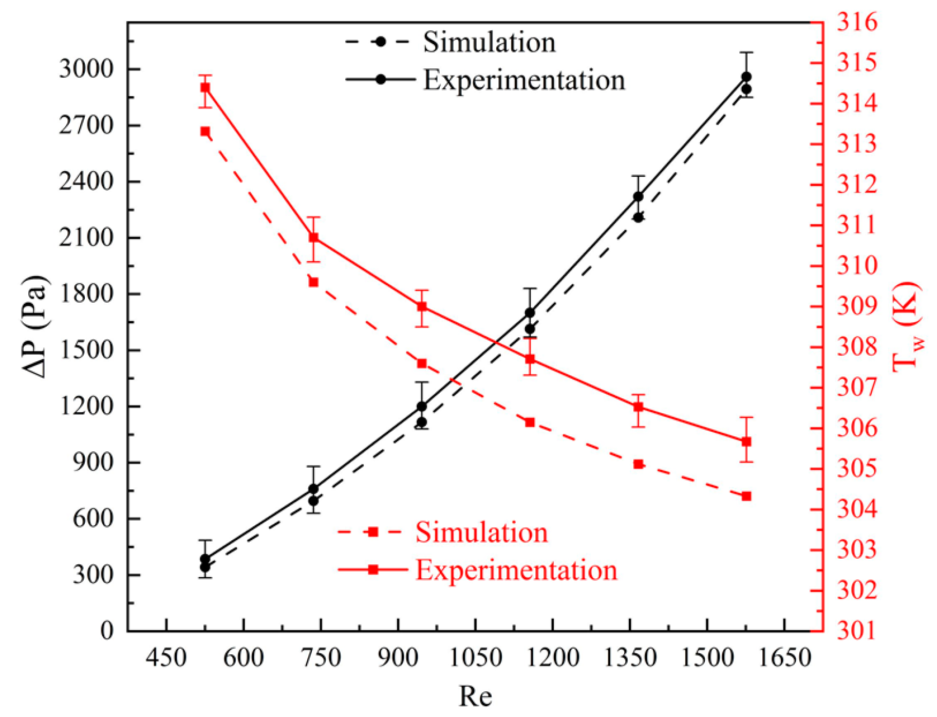
Experimental data were collected using the apparatus depicted in
Figure 3, employing a flow channel radiator with parameters s = 2 mm, α = 120°, and β = 100% (inlet water temperature of 299.15 K, inlet flow rates ranging from 100 mL·min
−1 to 300 mL·min
−1, and a flow rate gradient of 40 mL·min
−1). The central temperature of the base surface of the flow channel radiator T
w and the overall pressure difference ΔP were taken as the verification indicators. The results shown in
Figure 7 reveal that the experimental and simulated values of ΔP are very close across each Reynolds number gradient. However, the simulated values of T
w are consistently lower than the experimental values for each Reynolds number gradient. This discrepancy is attributed to the fact that in the simulation model, the heat source and flow channel radiator are regarded as ideally connected, thus rendering a heat-transfer capability that is somewhat higher than actuality, leading to slightly lower simulated values. The overall maximum error does not exceed 5%. Considering the verification results for both ΔP and T
w, the modeling and simulation of the flow channel radiator in this study are effective and suitable for subsequent simulation research.
4.2. The Characteristics of the Radiator
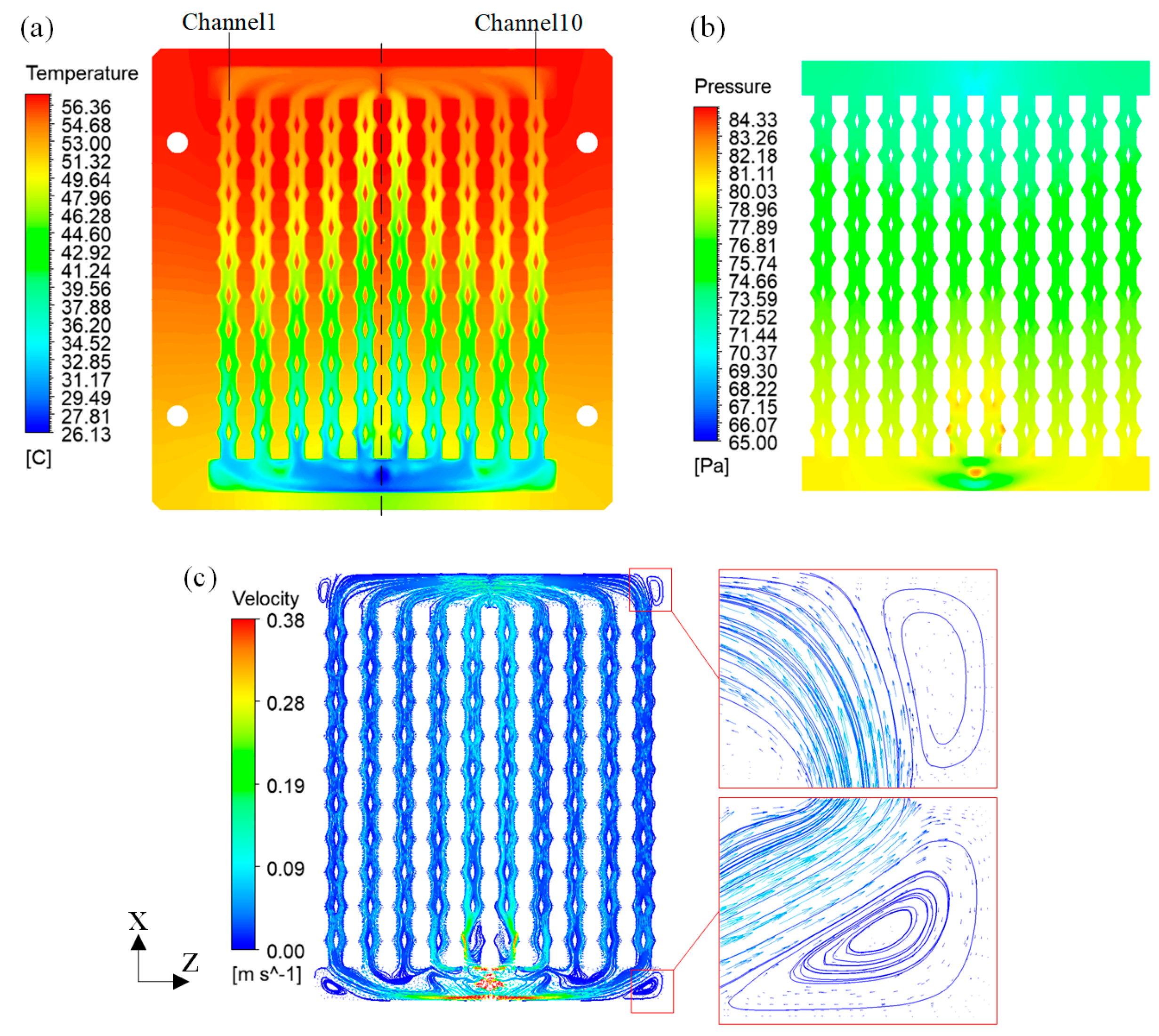
For a flow channel radiator with parameters s = 2 mm, α = 150°, and β = 100%, a simulation was conducted at a flow rate of 60 mL·min
−1 to study the radiator’s characteristics. The simulated cloud diagrams were extracted at the cross-section H/2, and the results are presented in
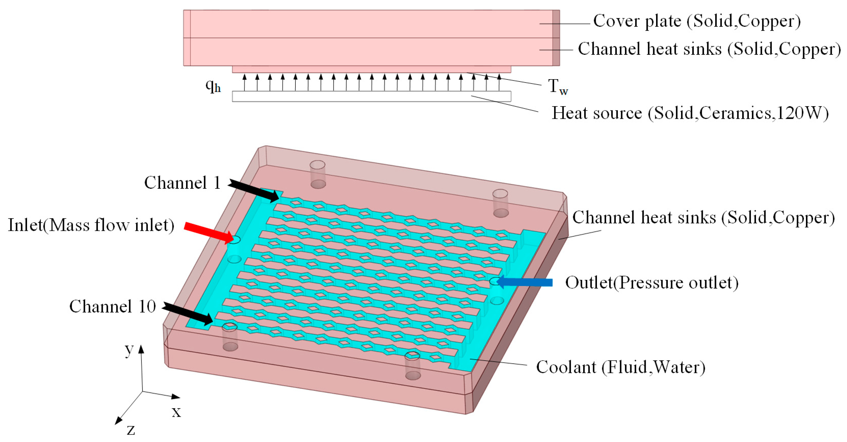
Figure 8a–c. The temperature of the cross-section, the pressure of the channels, and the velocity of the fluid within the channels all exhibit symmetric distribution. Channels closer to the center exhibit higher velocity, carrying away more heat but also manifesting increased pressure. Vortices appear at the four corners of the radiator. As these are distant from the heat-exchange area, they do not impact the cooling performance.
Due to the symmetry of the radiator’s overall structure and the identical geometric parameters (s, α, and β) in each channel, the distribution of water flow to every channel is symmetrical, resulting in the evaluation indicators for all channels being symmetrical as well. The apparent friction factor and Nusselt numbers for each channel are illustrated in
Figure 9a,b, respectively. It is evident that the central channel exhibits the lowest apparent friction factor and Nusselt number, while the values for the other channels demonstrate varying degrees of increase. In the smooth, straight channels and the new channels, the apparent friction factor values for channels 5 and 6 are exceedingly close, leading to their having the lowest and equal heat-transfer enhancement factors among all channels. In consideration of the radiator’s symmetry and the minimal heat-transfer enhancement factor in the central channel, subsequent simulations will extract the Nusselt number, thermal resistance, apparent friction factor, and heat-transfer enhancement factor of channel 5 as output data.
4.3. The Impact of Geometric Parameters on the Heat Sink
4.3.1. Effects of Fin Angle α
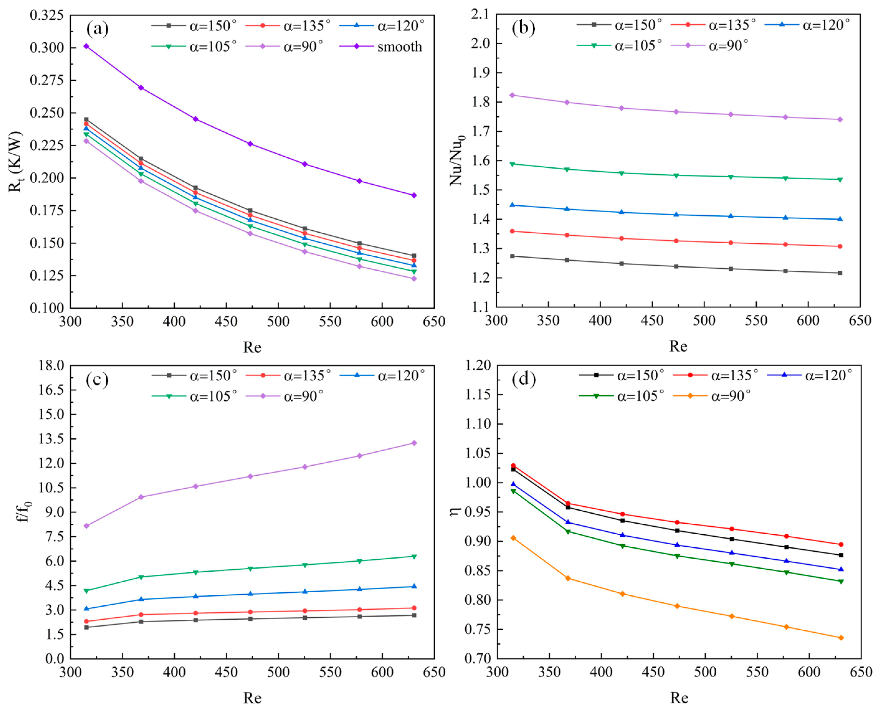
Figure 10 shows the effect of design variable α on the performance of channel when the other design variables are kept constant (β = 100%, s = 2).
Figure 10a displays the thermal resistance R
t at various Reynolds numbers Re and different fin angles. The thermal resistance R
t of the radiator is lower under all fin angles compared to the smooth, straight channels, indicating that the ridged fins within the channels effectively enhance heat transfer. As the fin angle decreases and the Reynolds number increases, thermal resistance gradually diminishes. The primary reasons for this can be explained by the velocity of the water flow and the heat-transfer surface area ratio ε between the new channels and the straight channels. As the fin angle decreases, ε increases, signifying a larger exchange area between the fluid and the solid, thereby improving the heat-transfer capability. On the other hand, when the Re increases and the fin angle decreases, the average fluid velocity within the channel rises. Considering the aforementioned factors, thermal resistance gradually decreases, and the channel radiator exhibits the lowest thermal resistance when α = 90°.
Figure 10b illustrates the Nusselt number ratio Nu/Nu
0 at various Reynolds numbers and different fin angles α. The Nusselt numbers under all fin angles are greater than those in smooth, straight channels. This is because the fins disturb the fluid’s velocity, exerting a perturbing effect on the fluid regardless of the fin angle. The disturbance is weakest, and the heat-exchange area between the fluid and the solid is minimal when α = 150°, resulting in the lowest Nu/Nu
0. From the perspective of Nusselt numbers, the heat-transfer performance is superior at α = 90° compared to smooth, straight channels, reaching up to 1.82 when Re = 315.32.
Figure 10c exhibits the relative friction factor f/f
0 at various Reynolds numbers and different fin angles α. It can be observed that regardless of the fin angle, the fluid flow resistance within the channels is higher than that in smooth, straight channels, and it increases with the Reynolds number. When Re remains constant, the variation in fin angle has a dramatic effect on flow resistance and increases sharply as the fin angle decreases. At α = 90° and Re = 630.64, f/f
0 is 13.25, indicating that the flow resistance is 13.25 times that of smooth, straight channels. This signifies a marked deterioration in flow performance, primarily due to an excessive pressure difference in the channel when α = 90°. Therefore, excessively small fin angles should be avoided in the current design. Angles of α = 150° and α = 135° may be prioritized, as they result in a flow resistance no more than three times that of smooth, straight channels.
Figure 10d shows the heat-transfer enhancement factor η
f at various Reynolds numbers and different fin angles α. η
f decreases with increasing Re across all angles, signifying that the radiator’s overall performance is better at lower flow rates. When Re remains constant, η
f first increases and then decreases with the reduction of the fin angle. At α = 90°, η
f is at its lowest, where the pressure-drop penalty far outweighs the heat-transfer enhancement, resulting in η
f being only 0.74 at Re = 630.64. Therefore, in the current design, angles of α = 150° or α = 135° should preferably be utilized.
4.3.2. Effects of Height Ratio β
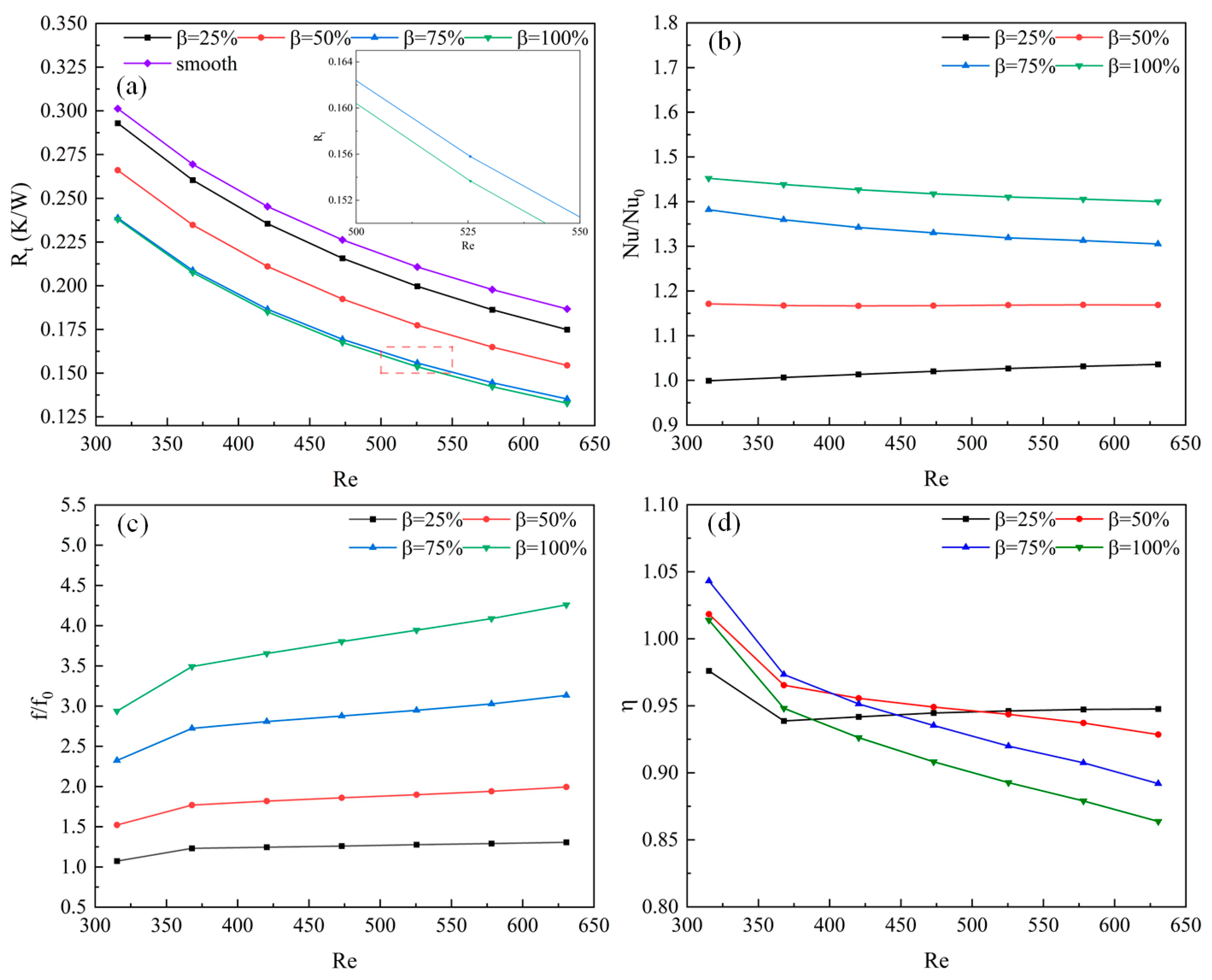
When s = 2 and α = 120° and they remain constant, the influence of the design variable β on channel performance is illustrated in
Figure 11.
Figure 11a depicts the thermal resistance R
t at various Re and different height ratios. From the graph, it can be distinctly observed that the thermal resistance of all channels with different rib heights is lower than that of the smooth, straight channels, and furthermore, it diminishes gradually with the increase in Re. When the Re is constant, R
t first decreases with the increase in β, eventually stabilizing. The reason for this may be that when β = 75%, it already provides a sufficiently large heat-transfer area, and even if β further increases to 100%, the resultant enhancement in heat-exchange performance will not increase substantially.
Figure 11b exhibits the Nusselt number ratio Nu/Nu
0 at various Re and different height ratios. When β = 75% and 100%, Nu/Nu
0 tends to decrease with the increase in Re, whereas when β = 25% and 50%, Nu/Nu
0 exhibits an ascending trend with the growth of Re. When Re remains constant, Nu/Nu
0 gradually increases with the enhancement of β. The reason for this could be the amplification of the heat-exchange area between the fluid and the solid as β grows, coupled with the fact that a larger β results in an increased ability of the ribs to disturb the fluid. Therefore, compared to the smooth, straight channels, the heat-transfer performance of the radiator is optimal when β = 100%, with Nu/Nu
0 consistently exceeding 1.4.
Figure 11c demonstrates the relative friction factor f/f
0 at diverse Re and different height ratios, revealing that the fluid flow resistance within channels at all height ratios surpasses that of the smooth, straight channels. When β = 75% and 100%, f/f
0 progressively escalates with the increase in Re; in contrast, when β = 25% and 50%, f/f
0 exhibits a tendency to stabilize with the growth of Re. This phenomenon might be attributed to the comparatively small pressure differential in the channels when β = 25% and 50%. Under the prevailing conditions, f/f
0 signifies that any value of β will influence flow performance; however, compared to smooth, straight channels, at β = 25% and 50%, f/f
0 does not exceed 2. Hence, in the current design, consideration can be prioritized for β = 25% and 50%.
Figure 11d portrays the heat-transfer enhancement factor η
f at various Re and different height ratios. With the exception of β = 25%, all heat-transfer enhancement factors diminish with the growth in Re. The rate of reduction for the heat-transfer enhancement factor at β = 50% is markedly attenuated compared to β = 75% and 100%, whereas at β = 25%, η
f initially declines and then steadily ascends with the increase in Re, and when Re > 507.5, its curve becomes the highest. In summary, if Re > 507.5, a preference for β = 25% is recommended; if Re < 507.5, a priority for β = 50% and 75% is advised.
4.3.3. Effects of Rib Space s
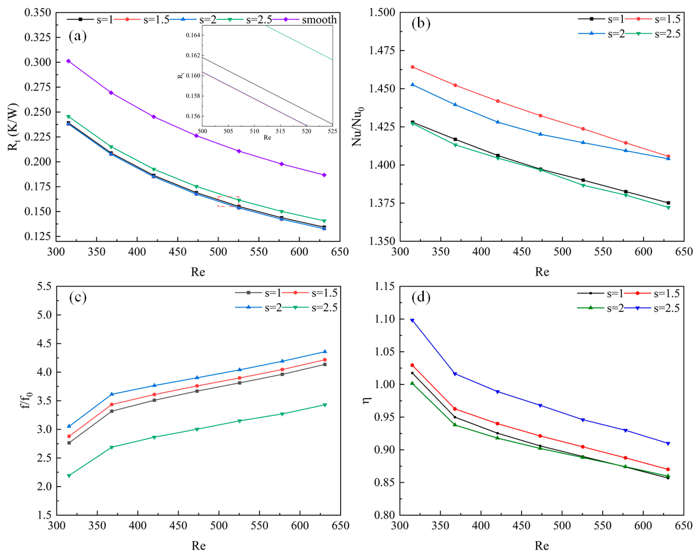
When β = 100% and α = 120° and they remain constant, the influence of the design variable s on channel performance is illustrated in
Figure 12.
Figure 12a reveals the thermal resistance R
t at varying rib spacings. It is salient that the thermal resistance of the radiators at all rib spacings is inferior to that of the smooth, straight channels, and all the curves are closely congruent. The reason for this is that the alteration in rib spacing nearly fails to modify the ratio of the heat-transfer area between the new channel and the straight channel, thus resulting in equivalent heat-transfer characteristics.
Figure 12b illustrates the Nusselt number ratio Nu/Nu
0 at different Re and different rib spacings. Aside from when s = 2, Nu/Nu
0 noticeably declines with an increase in Re, reaching its maximum when s = 1.5. Nu/Nu
0 at s = 1 and 2.5 are minimal and nearly identical. However, when s = 2, the rate of decrease in Nu/Nu
0 lessens when Re exceeds 472.98, and according to the current trend, it can be estimated that Nu/Nu
0 will become the greatest when Re surpasses 630.64 at s = 2. In summary, the heat-transfer performance is substantially reduced as Re increases.
Figure 12c depicts the relative friction factor f/f
0 at various Re and different rib spacings. It can be discerned that regardless of the spacing of the ribs, the fluid flow resistance within the channel is higher than that in a smooth, straight channel, and it increases with the enhancement of Re. When Re remains constant, f/f
0 initially rises with an increase in s and subsequently diminishes, reaching its minimum when s = 2.5; hence, in the present design, a preference may be given to s = 2.5. Furthermore, the graph reveals that when s = 1, 1.5, or 2, the trends of their curves are consistent and the values differ insignificantly, which could be attributed to the degree of disturbance to the fluid in the channel being almost the same under current conditions.
Figure 12d illustrates the heat-transfer enhancement factors η
f at varying Re and different rib spacings. All the curves exhibit a similar trend, with a maximum observed when s = 2.5. Overall, it can be anticipated that when Re exceeds 630.64, the heat-transfer enhancement factor will rapidly diminish following the current trend.
4.4. The Application of Heat Sinks
Based on the analysis from the previous section, conclusions can be drawn as follows: 1. α = 150° or α = 135° is appropriate; 2. If Re > 507.5, the preference should be given to β = 25%, whereas if Re < 507.5, the preference should be given to β = 50% and 75%; 3. s = 2.5 may be considered with priority.
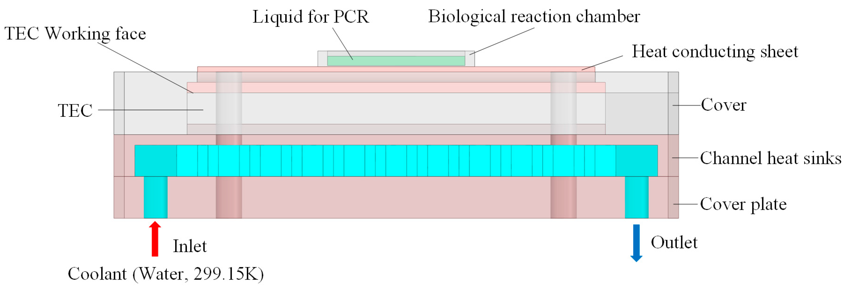
The channel heat sink studied in this article is used in PCR reaction devices, as shown in
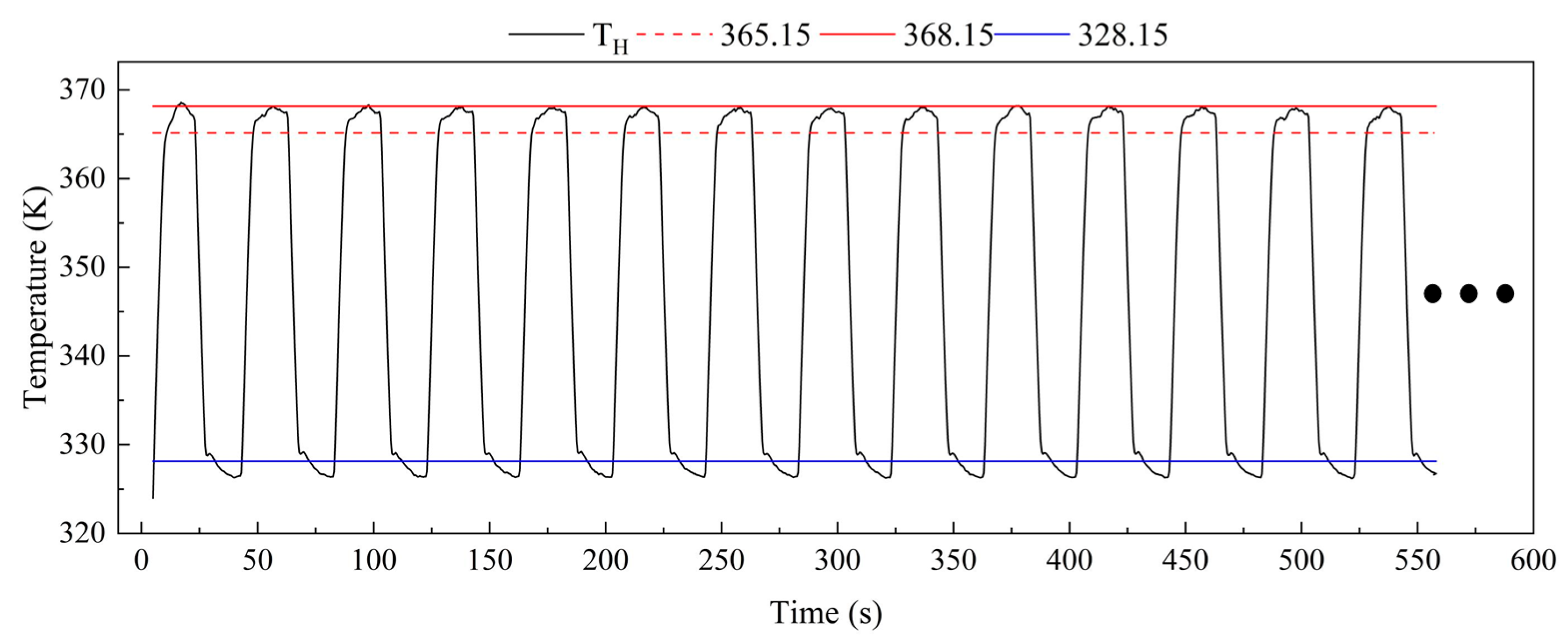
Figure 13. A thermoelectric cooler (TEC) is controlled programmatically to generate the temperatures required for the PCR process, and the TEC working face transmits this temperature to the biological reaction chamber through a heat-conducting sheet, ultimately facilitating the liquid within the reaction chamber to complete DNA amplification. The surface temperature requirements for a thermal conducting sheet are: generating a cyclical temperature of 328.15 ± 3 K to 368.15 ± 3 K (45 cycles, with the maximum exceeding 365.15 K and the minimum falling below 328.15 K), and a rate of temperature rise or fall not less than 5 K/s. Owing to the characteristics of the TEC, when the working face is heated, the opposite side must be cooled, and the cooling capability is determined by the heat dissipation capacity of the channel heat sinks.
In practical testing, we utilized a channel heat sink with α = 135°, β = 25%, and s = 2.5, conducting tests at a flow rate of 100 mL·min
−1 (Re = 525.53) and water temperature of 299.15 K. The measuring apparatus was based on the experimental setup shown in
Figure 3, using a data acquisition instrument to capture the temperature of the heat-conducting sheet surface (the contact face between the heat-conducting sheet and the biological reaction chamber, TH), as depicted in
Figure 14. The test results indicated that the surface temperature of the heat-conducting sheet nearly reached 368.15 K at its peak during each cycle, with the minimum consistently below 328.15 K; the heating rate reached 7.9 K/s, and the cooling rate achieved 7.8 K/s. Under these temperature conditions, the PCR reaction could be completed. Overall, this channel heat sink is capable of fulfilling the heat dissipation requirements. The symbol "···" shown in
Figure 14 indicates that the rest of the curve is the same as the current curve for 45 cycles.
