1. Introduction
Pumped Storage Hydropower (PSH) is currently one of the most mature energy storage technologies in the world [
1] and the largest to date [
2]. PSH has flexibility and good storage capacity, so it has been widely used in the field of renewable energy power generation [
3,
4]. At present, China is in a critical period of green and low-carbon energy transformation and development. With the large-scale and high-proportion development of new energy sources such as wind power and photovoltaic power generation, the demand for power regulation is more urgent. The construction of a new power system with new energy as the main body puts forward higher requirements for the development of pumped storage [
5]. In a pumped storage unit, because the high-head pump turbine has many advantages, such as a high speed, small flow, small size and high head, the design of the pump turbine has recently tended to have a high head [
6]. Due to the higher pressure of the high head unit, the gap leakage problem is more obvious than that of the ordinary unit, which is a scientific problem that needs to be solved urgently.
Clearances cause leakage losses due to part of the water not flowing through the runner and friction losses due to torque applied to the rotor [
7]. Kim SJ et al. [
8] studied the gap flow characteristics of the upper and lower rings of the Francis turbine runner and compared the changes in the hydraulic performance and flow characteristics of the unit with and without gaps.
The magnitude of the axial water thrust on the runner gap can often affect the stability of the unit in the axial direction, so the change in the axial water thrust caused by the gap has been deeply studied by several scholars. Studies have shown that, under load shedding conditions, the gap flow between the runner and the fixed part determines the precise simulation of the pump turbine pulsation characteristics and unsteady vortex [
9]. Hou XX et al. [
10] used the method of combining PIV measurements and a numerical simulation to determine the reasons that affect the gap flow pattern and axial water thrust, and they quantitatively expressed the axial water thrust as a function of the square of the rotational speed and the gap inlet pressure. Liu YS et al. [
11] studied the influence of different runner sinking axial deviation values on the axial water thrust of Francis turbines under rated conditions and found that, when the runner sinks, the axial water thrust on the upper ring increases, whereas the axial water thrust on the lower ring decreases. Zhou L et al. [
12] compared different impeller hub radii on the influence of the axial force, and it was found that the bevel trimming of the hub radius can effectively reduce the axial force.
The axial and radial clearance between the runner and its surrounding components is one of the key factors affecting the performance of the unit according to He LY et al. [
13]. The acoustic–solid coupling method and the improved one-way fluid–solid coupling method are used to study the influence of the radial and axial gaps between the runner and the surrounding structure on the additional mass and dynamic stress of the turbine runner. The results show that the axial gap has a greater impact on the additional quality factor of the in-phase, and the radial gap has a greater impact on the additional quality factor of the counter-phase and crown-dominant modes. Wang ZJ et al. [
14] studied pressure pulsation in the gap between the runner and the guide vanes through a numerical simulation, and they found that, in this gap, the run-away point in the braking zone of the turbine generates a low-frequency component caused by the rotating stall. When the pump rotates in the reverse direction as a water turbine to generate electricity, the radial clearance between the impeller blade tip and the volute tongue affects the pump as one of the main factors of the turbine’s performance. Yang SS et al. [
15] calculated the unsteady flow field of a pump as turbine and found that, due to the rotor–stator interaction (RSI) between the impeller and the volute, low-frequency pressure pulsations are generated in the impeller, and high-frequency pressure pulsations are generated in the volute and propagate in the flow channel. When the radial clearance increases, the pressure pulsation amplitude of the impeller remains unchanged, whereas the pressure pulsation amplitude in the volute increases. The authors of [
16] compared the numerical results of the gap flow field between the impeller and the pump cover (cover) with the experimental results and found that the two results were very similar, and as the gap increased, the interference of the water flow out of the gap on the impeller inlet flow increased. Yonezawa K et al. [
17] used numerical simulation methods to explore the principle of sand erosion in the runner gap and used experimental research methods to study the vortex flow characteristics in the gap. It was found that the second-stage sealing gap inlet was severely eroded, and vortex flow was generated between the first-stage and second-stage sealing gaps. Sonawat A et al. [
18] determined the range of the axial clearance and radial clearance that can affect the performance of positive displacement turbines through experimental research.
The mutual interference between the radial gaps of the dynamic and static cascades also has a certain impact on the performance of the turbine. Sato K et al. [
19] proposed an unsteady three-dimensional incompressible Navier–Stokes method and carried out a comparative verification of calculations and experiments on a centrifugal pump with a vane diffuser, and they then carried out numerical simulation research on the radial clearance on a hydraulic turbine. The research shows that, as the radial clearance of the blade cascade decreases, the predicted efficiency of the hydraulic turbine decreases. Shu P et al. [
20] studied the effect of the axial clearance between the static cascades of marine steam turbines on the flow field and found that, as the axial clearance increases, the blade pressure fluctuation decreases, but the vortex structure at the blade root increases, resulting in a decrease in unit efficiency.
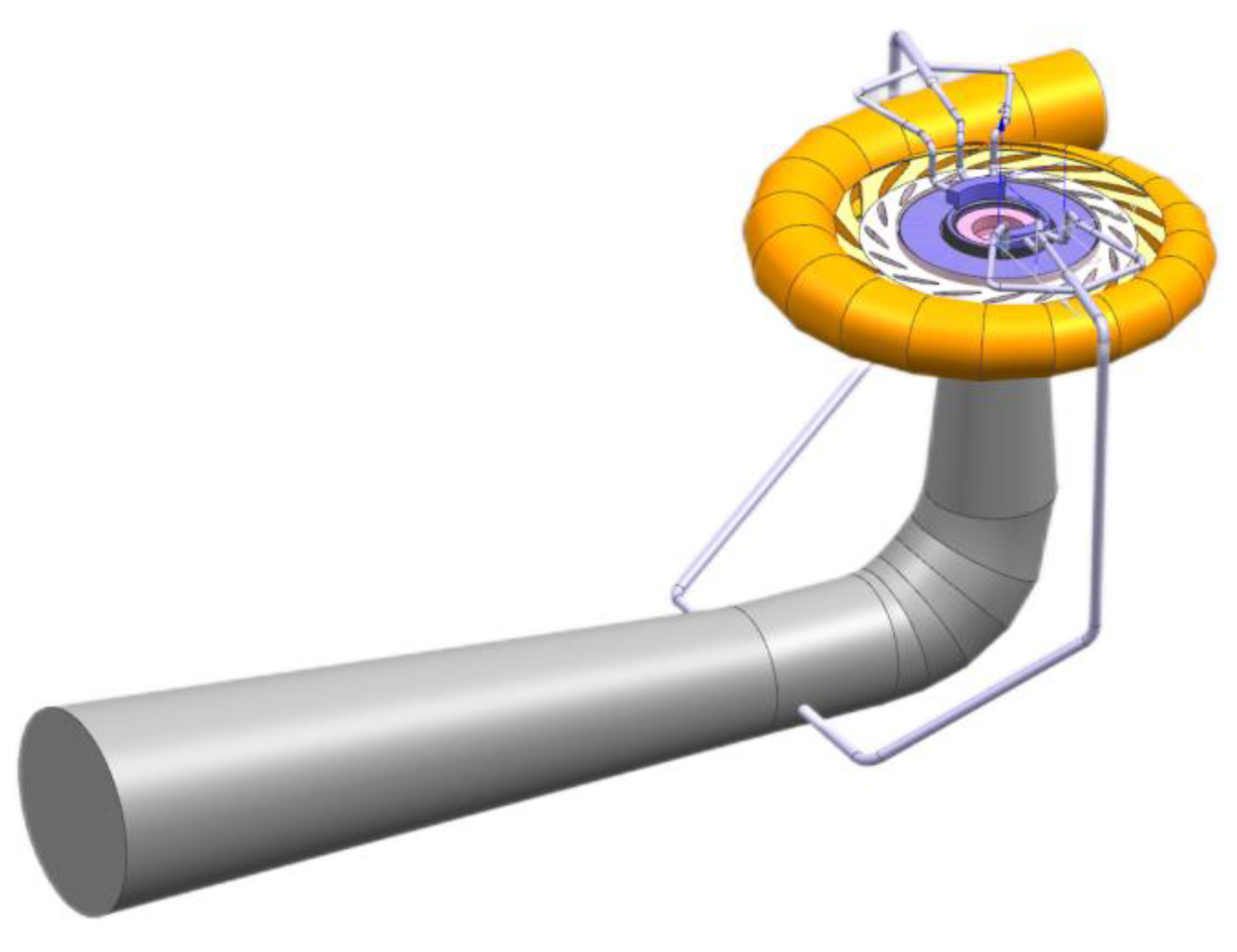
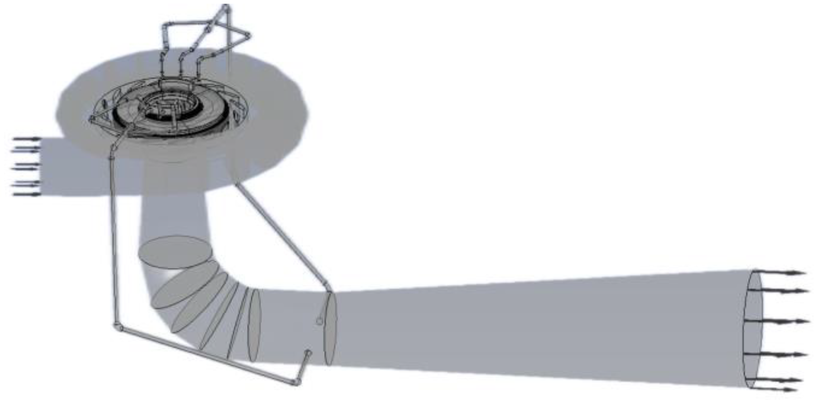
Some scholars extracted the gap channel and calculated the pure gap separately. When the gap is connected with the mainstream basin, the full channel is generally calculated. In this paper, in order to truly and fully reflect the flow state in the gap and accurately set the boundary conditions, a three-dimensional full channel model is established to calculate the whole basin. The influence of the thickness of the runner crown clearance on the pressure pulsation and axial stability of the runner of a reversible pump turbine is studied by means of a full flow passage numerical simulation. In
Section 2, the basic theory and simulation setup, including meshing, border condition configuration, etc., are presented. In
Section 3, the calculation results, such as the energy characteristics, pressure distribution and axial hydraulic pressure, are obtained and analyzed.
Section 4 gives the main conclusions. The results show that the area with large changes in pressure and velocity in the upper crown clearance flow field is the labyrinth ring seal, and the pressure and velocity of the flow through the gap are greatly affected by the pressure and velocity of the flow through the gap. In addition, the vortex is generated near the pressure and velocity of the upper crown gap. The upper part, the upper crown inlet and the lower ring inlet of the vaneless region are the most disturbed by rotating components. The pulsation frequency of the axial water thrust on the upper crown, the lower ring and the blade and the resultant force of the axial water thrust increase with the increase in the clearance thickness of the upper crown.
3. Calculation Result Analysis
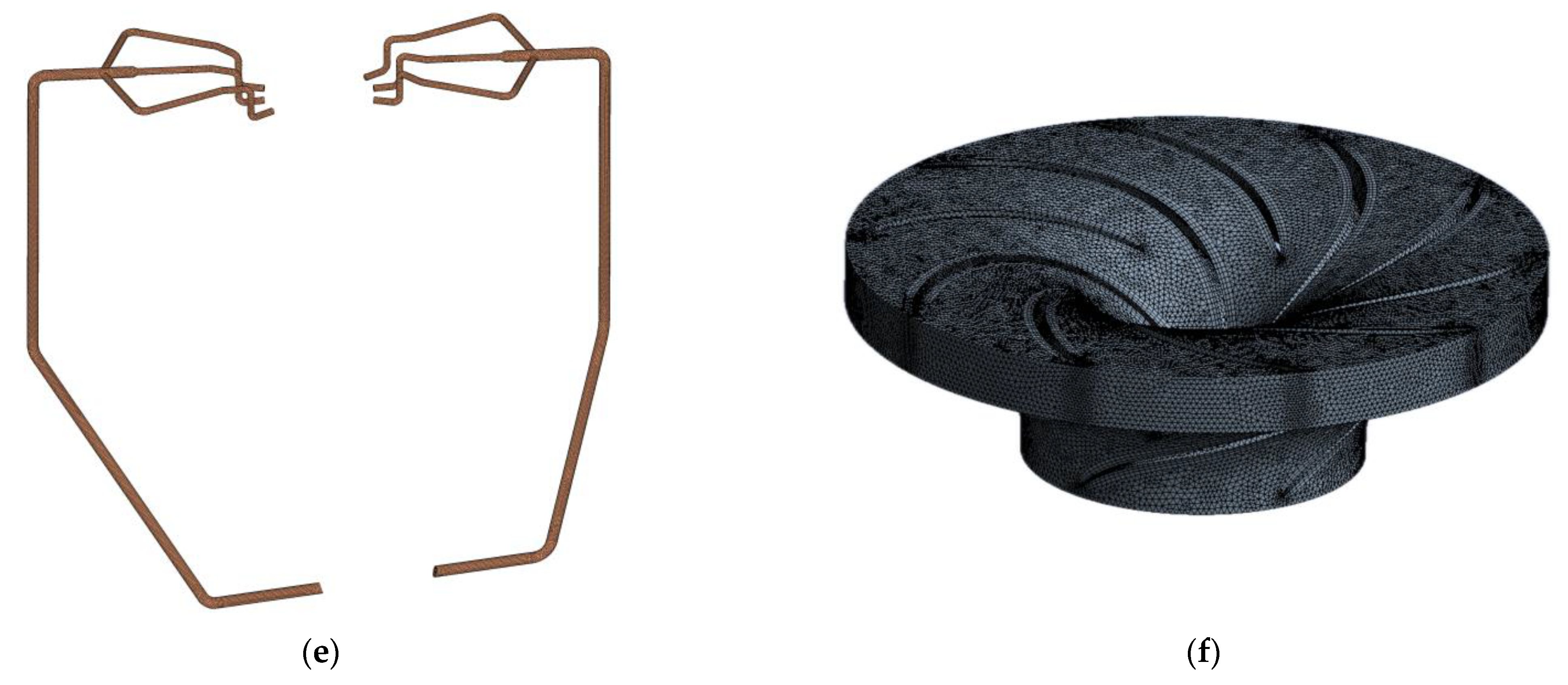
3.1. Mesh Quality Check
Under the working conditions of the turbine, the calculation results of the head, flow rate and power of the unit under rated working conditions are shown in
Table 3. The maximum error between the numerical calculation results and the design parameters is 3.94%, which proves the reliability of the numerical calculation method.
3.2. External Characteristic Analysis
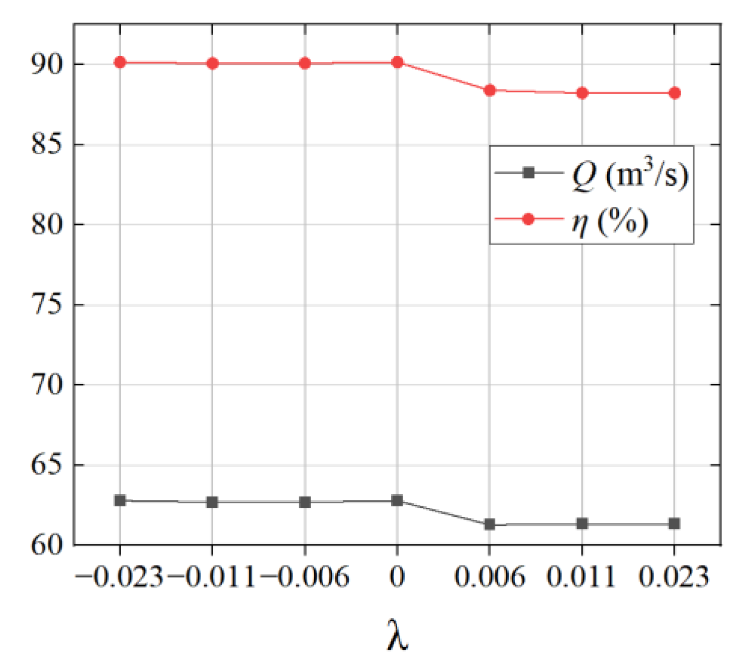
As shown in
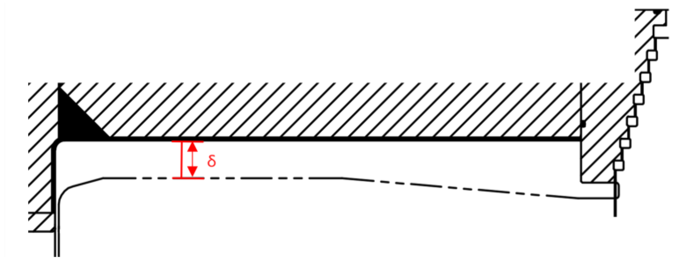
Figure 5, when setting a reasonable clearance value, its influence on the efficiency η, flow Q, head H, etc., should be considered comprehensively, and the head H is given. As the relative clearance increases, it has little effect on efficiency and flow at first, and it then gradually increases. Increasing the relative gap causes the flow rate to decrease because the leakage of the unit increases with the increase in the gap. In addition, volume loss increases, and the efficiency decreases.
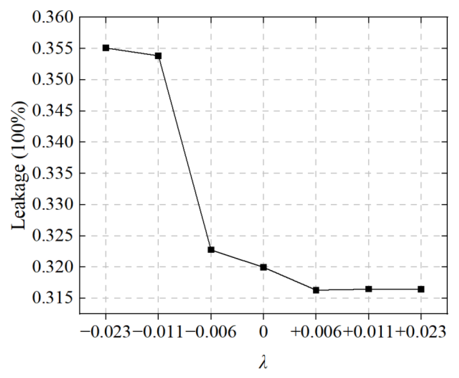
3.3. Leakage When the Relative Clearance Is Different
A reasonable runner clearance can reduce clearance leakage, thereby improving the volumetric efficiency of the unit.
The leakage amount under different gap thicknesses is shown in
Figure 6. When the inlet and outlet boundaries are constant, the gap thickness of the upper crown decreases, and the flow passage between the upper crown and the top cover expands. In addition, the flow through the gap increases accordingly, and the increase in the flow causes the pressure value inside the gap to decrease, thereby causing the water thrust value to decrease.
3.4. Flow Field Analysis
3.4.1. Pressure Distribution at Different Gap Thicknesses
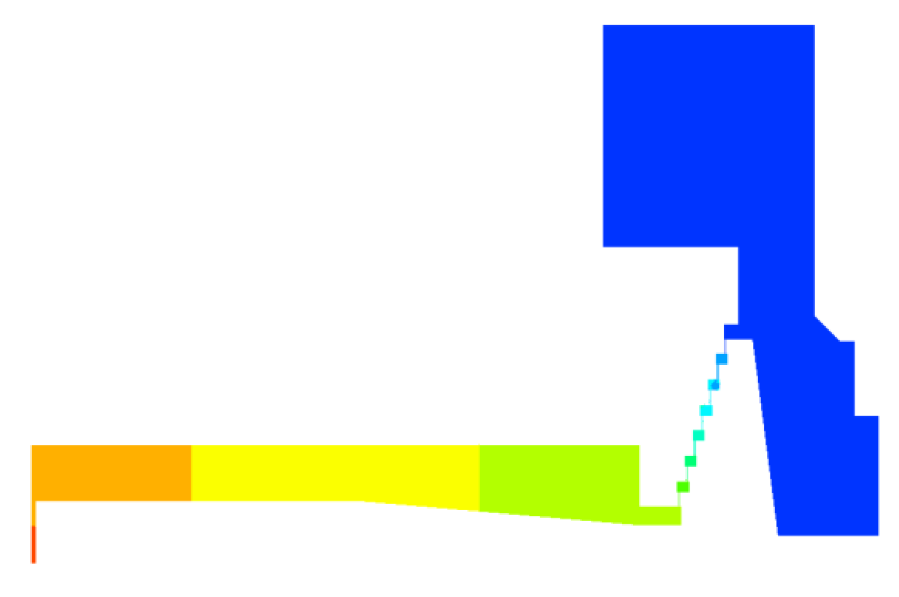
Different values of the crown seal gap of the runner have a disturbing effect on the flow field of the crown seal gap of the Francis turbine. It is necessary to carry out numerical simulation calculations of the whole channel of the prototype turbine and to then analyze the pressure field and velocity field. Because the flows in the upper and lower labyrinth rings basically do not affect each other, the change in the thickness of the upper coronal space mainly affects the flow in the upper coronal space.
It can be seen from the pressure calculation results that the pressure distribution under different gaps is basically the same. Only the labyrinth ring changes significantly, and the pressure value of the inlet and outlet changes with the gap. As shown in
Figure 7, the pressure gradient distribution in the gap flow channel is relatively uniform. The maximum pressure is distributed at the inlet of the crown gap, and the minimum pressure is at the outlet. From the inlet to the outlet of the gap, the pressure decreases continuously along the flow direction, and the pressure energy of the liquid is converted into kinetic energy, which also proves the effectiveness of the labyrinth seal on the decompression of the liquid. The pressure near the pressure equalizing tube is the smallest, which also proves that the pressure equalizing tube has a depressurizing effect.
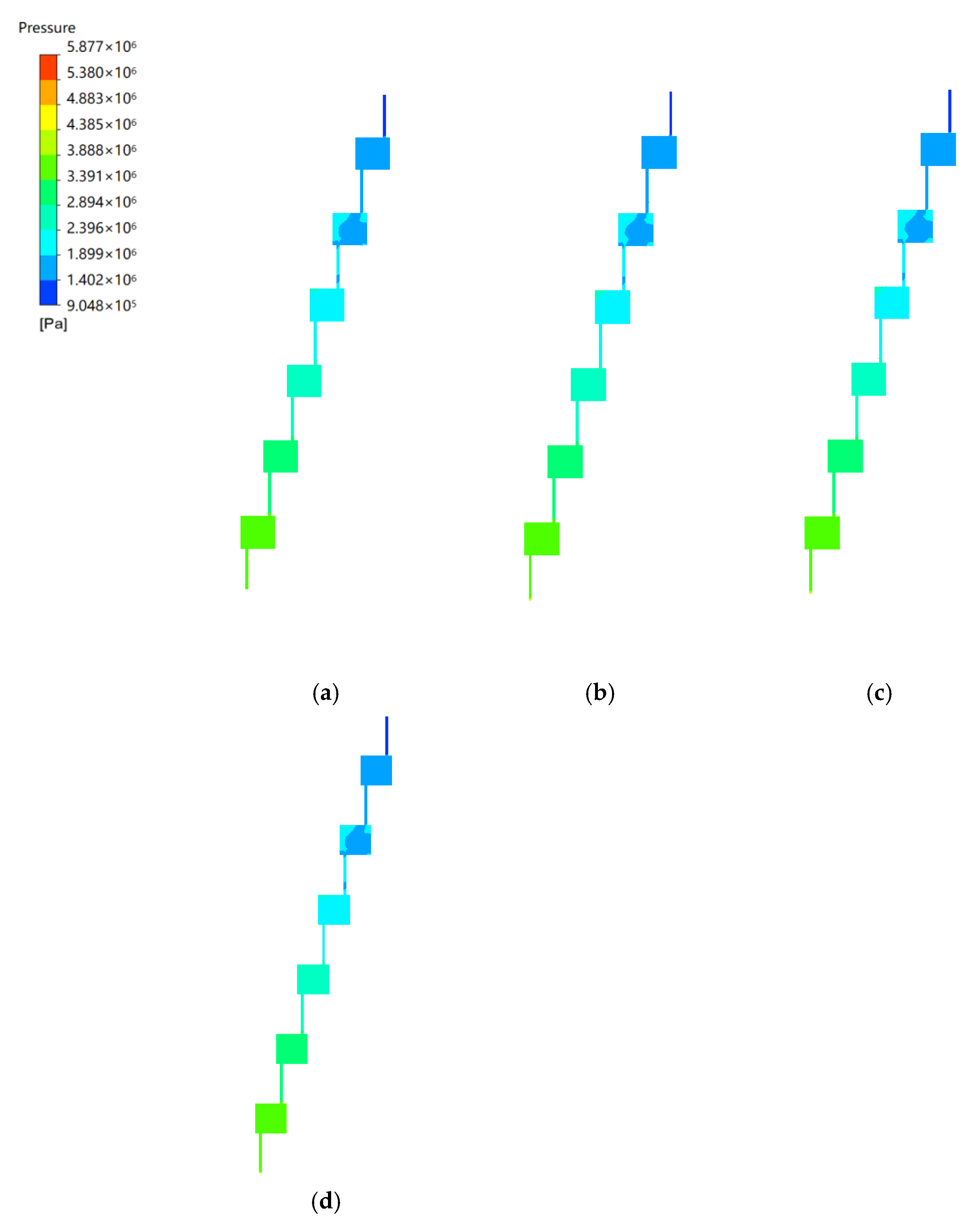
As shown in
Figure 7, when the thickness of the coronal gap is reduced, the pressure in the square cavity and narrow gap of the second-stage labyrinth ring near the exit of the gap changes. When
λ decreases by 0.006 and 0.011, the pressure tends to be uniform, and when it decreases to 0.023, the pressure distribution is consistent with the original thickness. When the thickness of the coronal gap increases, the pressures in the square cavity and narrow gap of the first-level and second-level labyrinth rings near the exit of the gap decrease. When
λ increases to 0.011 and 0.023, the pressure in the central area of the square cavity of the first-level labyrinth ring near the gap exit and the narrow gap connected to the pressure equalizing tube decreases significantly.
The pressure difference Δ
p between the inlet and outlet of the upper crown gap is shown in
Figure 8. The pressure difference is larger when the thickness of the upper crown gap is smaller. The pressure difference is the largest when the thickness increases by 0.011, and the pressure difference is the smallest when the thickness is reduced by 0.011.
3.4.2. Velocity Distribution at Different Gap Thicknesses
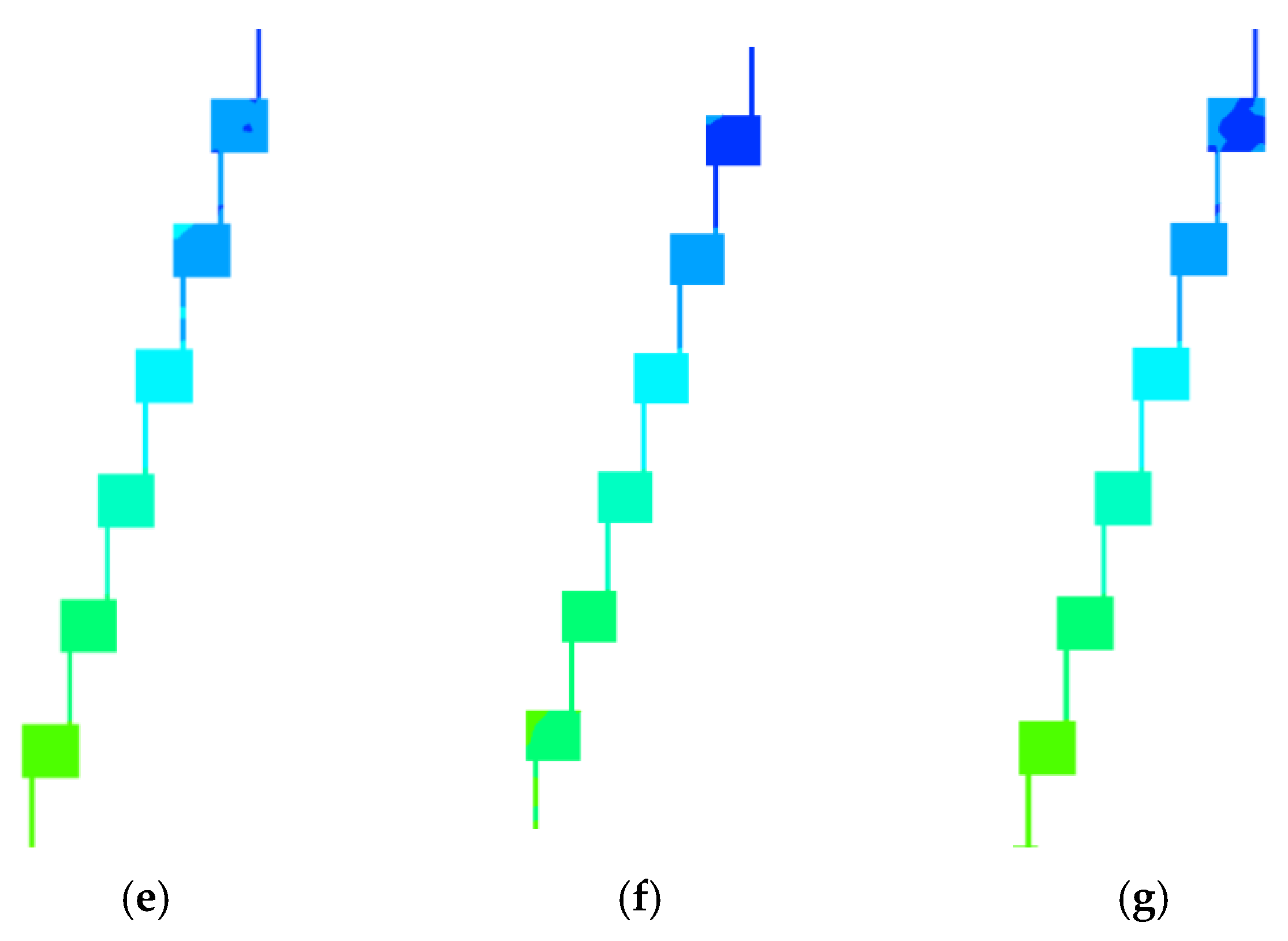
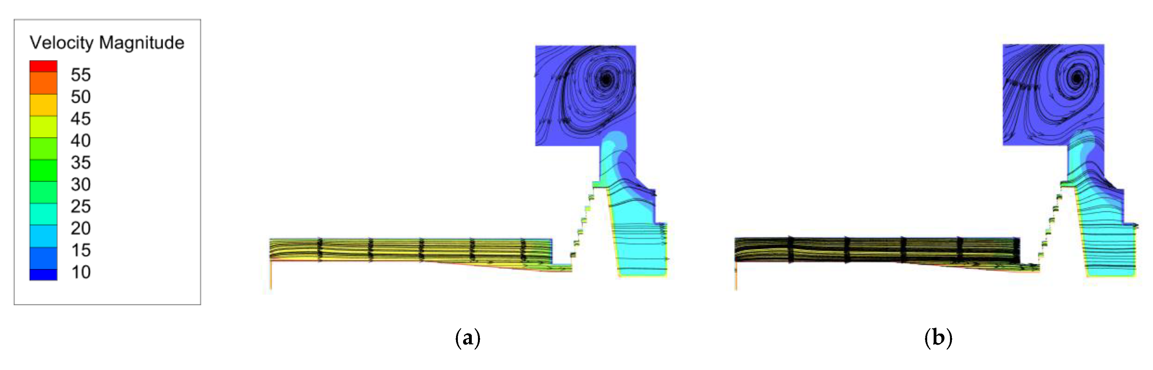
For the design of the main stream flow parts of the turbine, the principle is to minimize the hydraulic loss of the flow parts, and for the design of the labyrinth ring, it is necessary to increase the energy loss in the gap of the labyrinth ring as much as possible to reduce the flow loss and power loss, thereby increasing the flow efficiency and power efficiency. As shown in
Figure 9, the speed from the gap inlet to the outlet is a process of decreasing speed. The flow velocity at the gap inlet is relatively high, and the streamlines (noted as arrows) are relatively smooth. When the water flow passes through the labyrinth gap, it passes through many right-angle bends, the water flow resistance increases, the flow velocity decreases, and the hydraulic loss increases. Dispersion does not restore the pressure energy, and the energy loss of the liquid increases further. Moreover, with the increase in the gap, the vortex streamlines at the junction of the gap outlet of the upper crown and the flat pressure tube become denser, and the speed increases.
3.5. Monitoring Point Pressure under Different Gaps
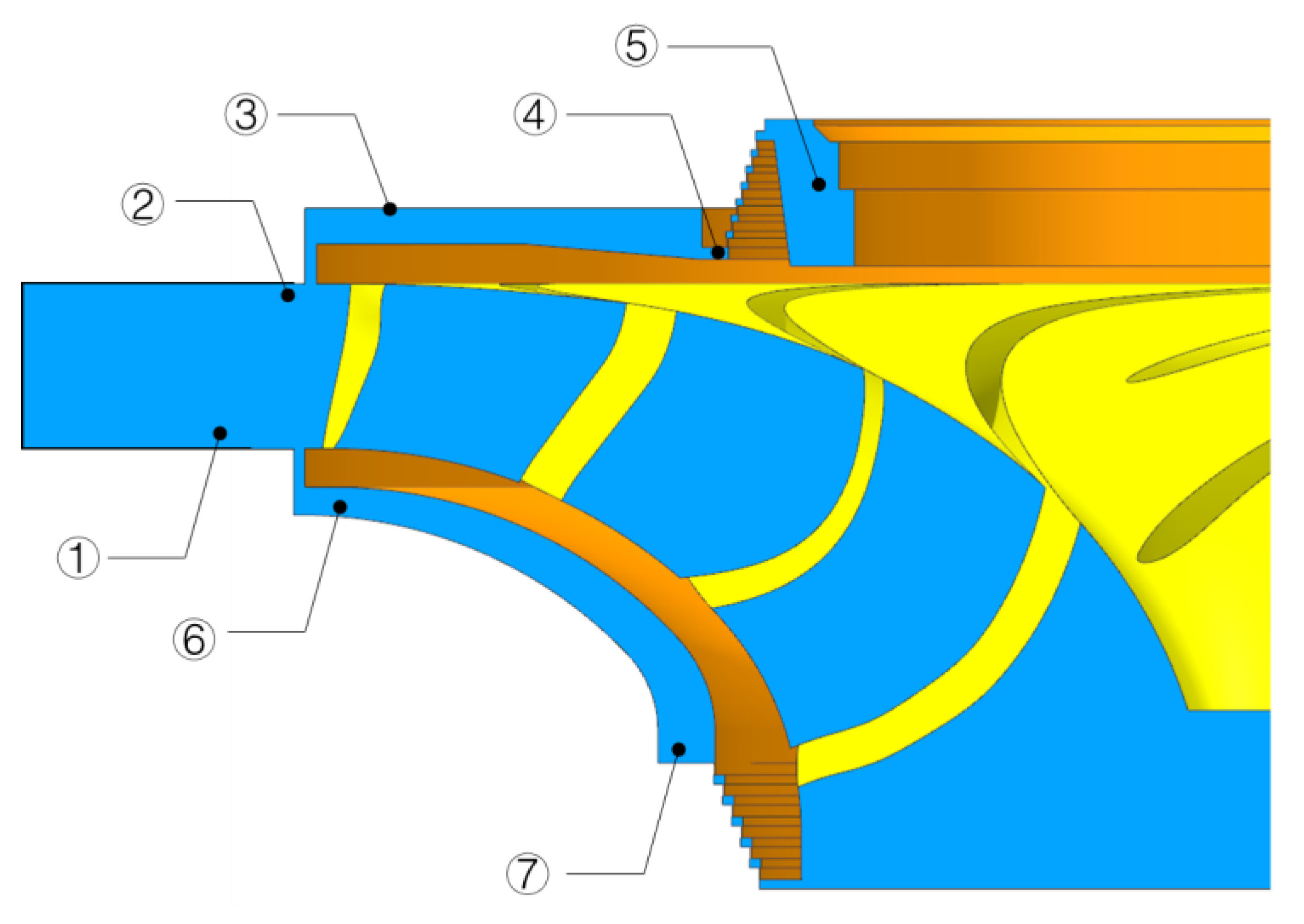
The pressure pulsation of the pump turbine is one of the causes of hydraulic mechanical vibrations, especially in large-scale units, due to the large size and low stiffness of the unit. In addition, the instability of the water flow can easily cause unit vibration, and in severe cases, it can cause fatigue damage to the unit components. According to the locations of the pressure pulsation measuring points of the unit, pressure pulsation monitoring points are set up at seven locations, including the lower part of the fixed guide vane, the upper part of the vaneless area, the entrance of the upper crown, the front of the upper crown labyrinth ring, the back of the upper crown labyrinth ring, the entrance of the lower ring and the front of the lower ring labyrinth ring, as shown in
Figure 10.
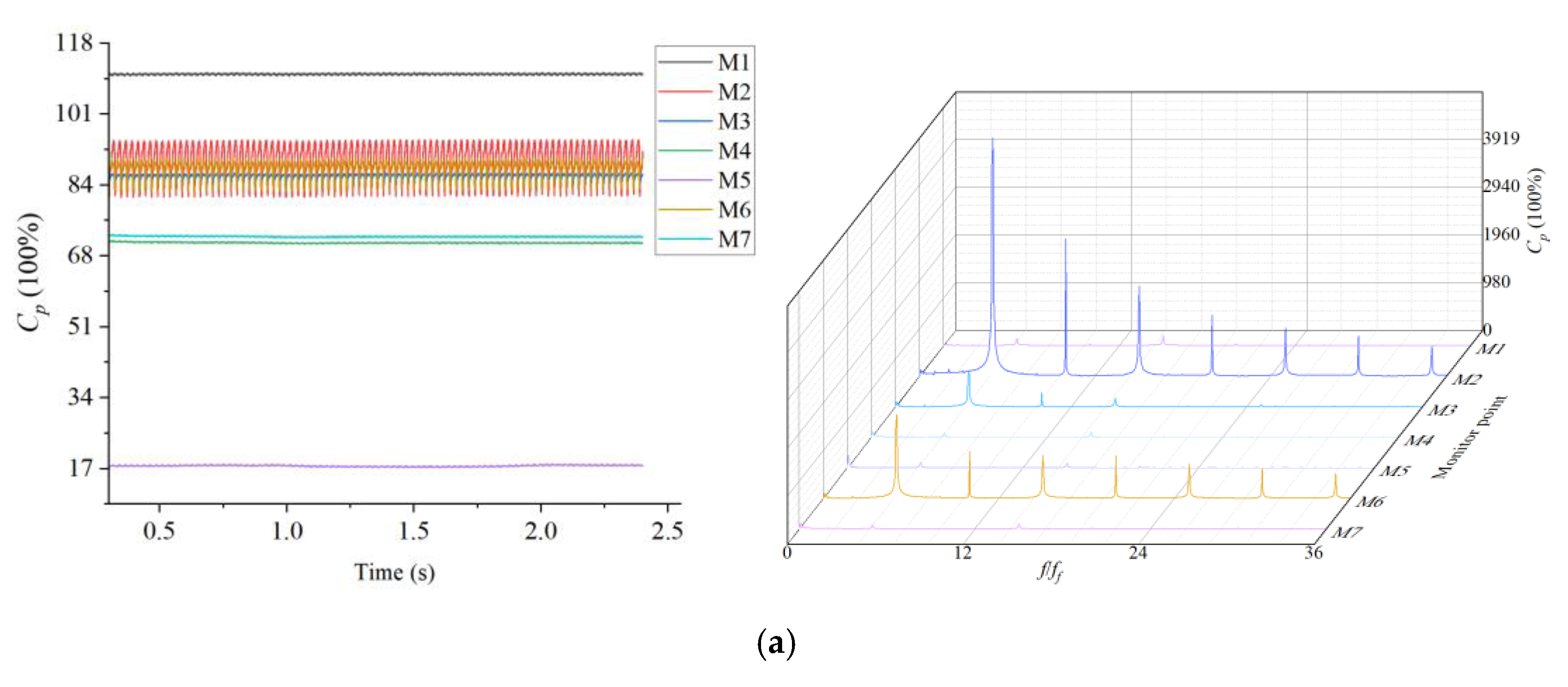
Cp is used to analyze the pressure of the pump turbine at different monitoring points.
Among them, P is the pressure measured at the monitoring point, and Hr is the rated water head value of the pump turbine under the turbine working condition.
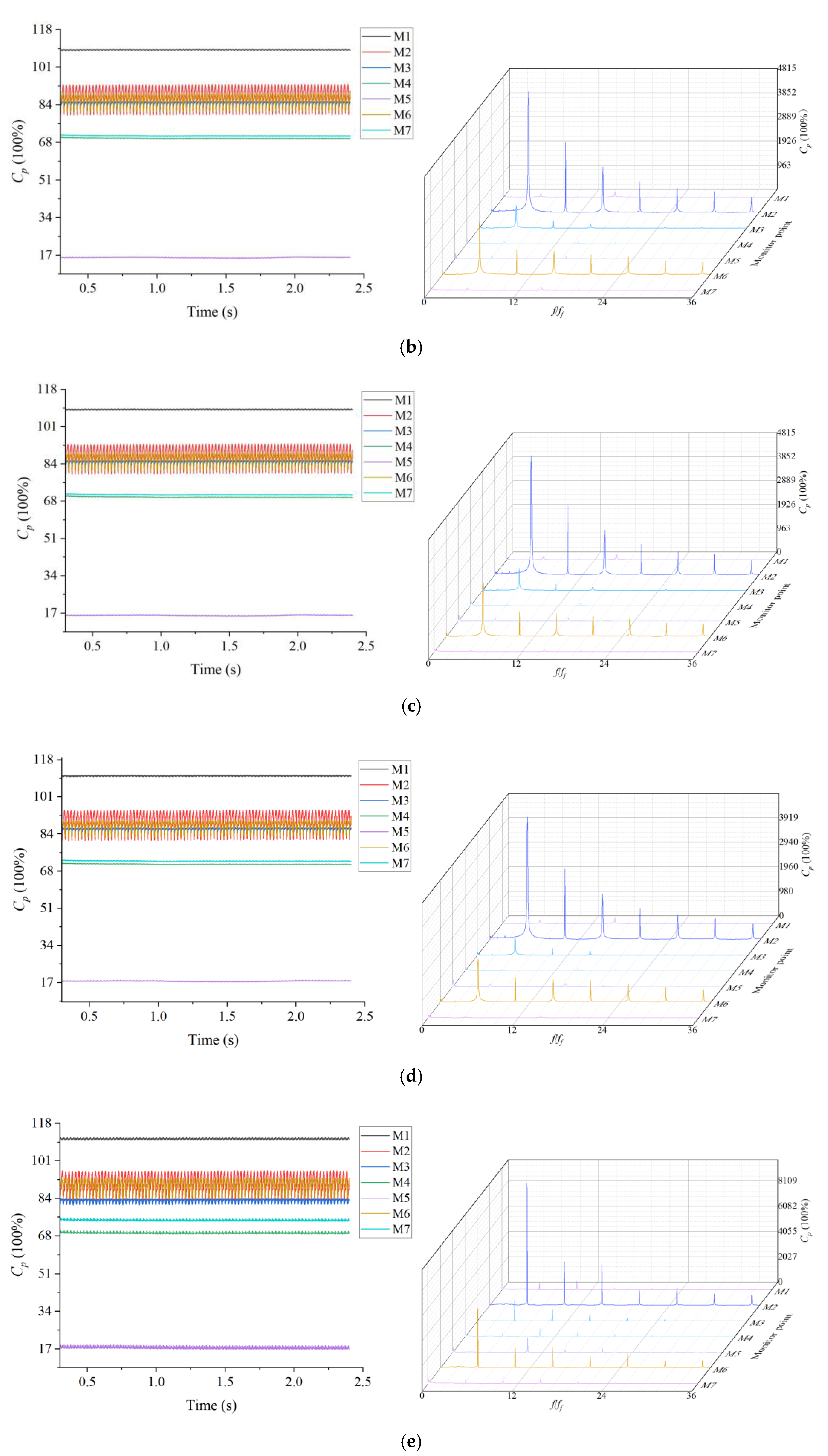
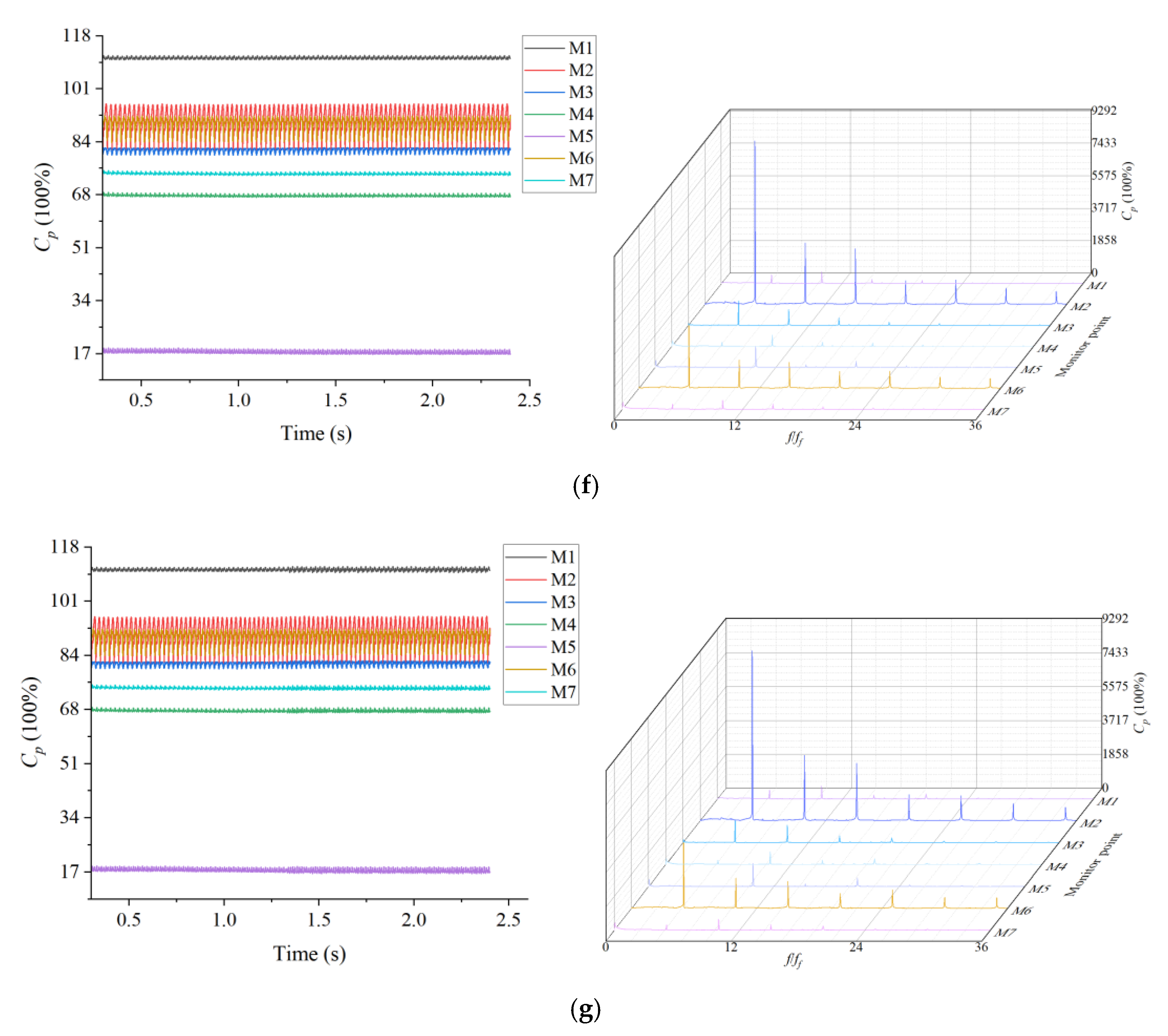
The time domain diagram shown in
Figure 11 shows that the pressure values of the pressure measuring points of each flow-passing component fluctuate relative to a certain reference value. Reducing the thickness of the upper crown gap has a weak effect on the pressure of the monitoring point, and increasing the thickness of the upper crown gap has a more obvious impact on the pressure at the entrance of the upper crown, in front of the labyrinth ring of the upper crown and in front of the labyrinth ring of the lower ring, which can reduce the pressure at the entrance of the upper crown and in front of the labyrinth ring of the upper crown. However, it increases the pressure in front of the labyrinth ring of the lower ring.
According to the frequency spectrum, the lower part of the fixed guide vane is far away from the runner, and the water flow at the outlet of the guide vane is relatively smooth under rated conditions. Therefore, the pressure pulsation at the lower part of the fixed guide vane is relatively small. Because the streamlines in front of the upper crown labyrinth ring, behind the upper crown labyrinth ring and in front of the lower labyrinth ring are relatively smooth and the flow state is stable, the pressure change is not obvious. Because the upper part of the bladeless area, the inlet of the upper crown and the inlet of the lower ring are relatively close to the runner, the interference of the rotating parts is the strongest. Therefore, the pressure pulsation of these three parts is more obvious. The frequency components of the three monitoring points are basically the same under different gap thicknesses. They are the passing frequency of the runner blade and its harmonic frequency. The main frequency of the pressure pulsation is 5 times the rotation frequency, and the secondary frequency is 10 times the rotation frequency. Moreover, under the working conditions of the turbine, the high-speed water flow quickly enters the runner after passing through the guide vanes and impacts the working surface of the blade, which causes RSI between the guide vanes and the runner, resulting in severe vibration and the largest pressure pulsation in the bladeless area between the guide vanes and the runner. Therefore, the high-frequency components are mainly concentrated in the bladeless area. The collision between the water flow in the bladeless area and the blades is also one of the important hydraulic factors for the vibration of the turbine under the working conditions of the turbine.
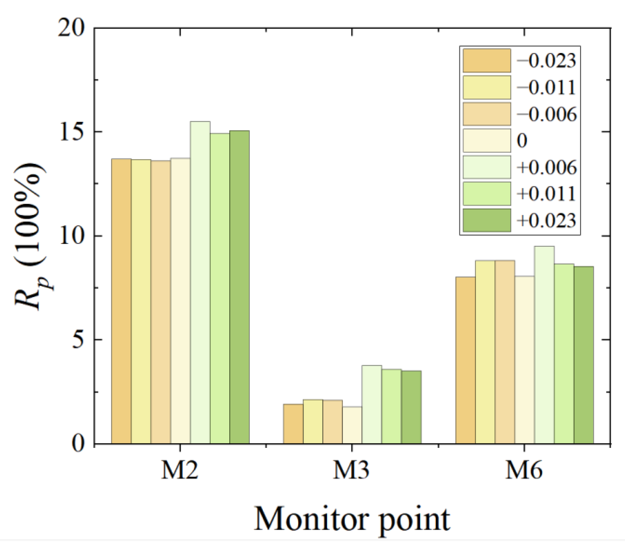
The pressure fluctuations in the vaneless area, the entrance of the upper crown and the entrance of the lower ring are obvious, corresponding to the monitoring points M2, M3 and M4, respectively. The relationship between the peak value of the pressure fluctuation and the water head is shown in Equation (12).
Among them, P is the pressure of the measuring point, ρ is the density of water (1000 kg/m 3), and g is the acceleration of gravity (9.8 m/s 2).
Figure 12 shows the relative pressure fluctuations of the three monitoring points. When the gap thickness of the upper canopy is reduced, the relative pressure fluctuations of the vaneless area are not greatly affected, but the
Rp values at the entrance of the upper canopy and the entrance of the lower ring increase. When the thickness of the gap is reduced to 0.023, the relative pressure fluctuations are almost the same as those corresponding to the original thickness. The relative pressure fluctuations in the vaneless area, upper crown entrance and lower ring entrance increase as the upper crown gap thickness increases, and the relative pressure fluctuation range is the largest when the upper crown gap thickness increases by 0.006.
3.6. Axial Force at Different Gap Thicknesses
If the axial force is upward, it is easy to lift the machine, and if the axial force is downward, it increases the load and frictional power of the thrust bearing. That is to say, the design requirements for the thrust bearing are relatively high, and if the axial water thrust of the pump turbine is vertically downward and the value is large, especially in the case of strong pulsation of the unit, the water thrust has a dual effect on the self-weight of the unit, which easily leads to friction of the thrust bearing and excessive deformation of the frame.
The unsteady calculation of the three-dimensional full flow channel is performed by changing the thickness of the upper crown gap. The rotation frequency of the wheel is shown in Equation (13).
Among them, n is the speed of the runner, 500 r/min, and the rotation frequency is 8.33 Hz.
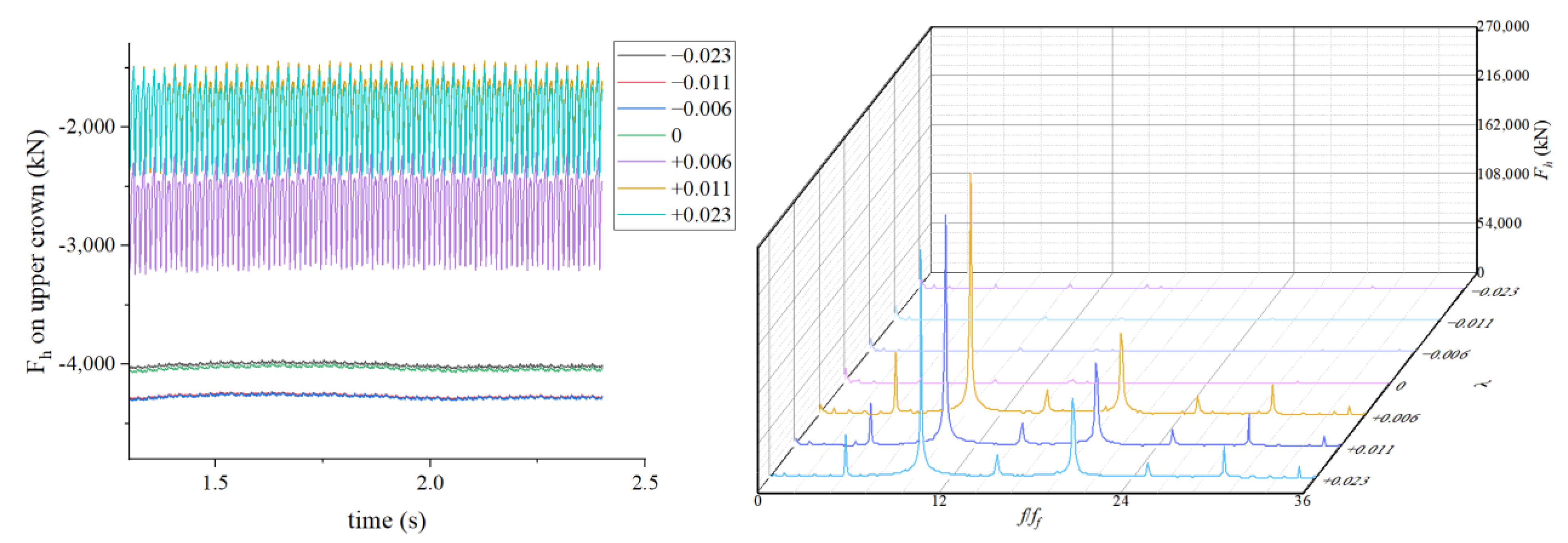
As shown in
Figure 13, taking the vertical downward direction as positive, the axial water thrust on the upper crown is positive. When the thickness of the crown gap is reduced, the axial water thrust on the crown also decreases with little fluctuation. However, when the thickness of the crown gap is reduced, the axial water thrust on the crown increases. By increasing the thickness of the crown gap, the main frequency of the axial water thrust on the crown is 10
ff, and the secondary frequency is 15
ff.
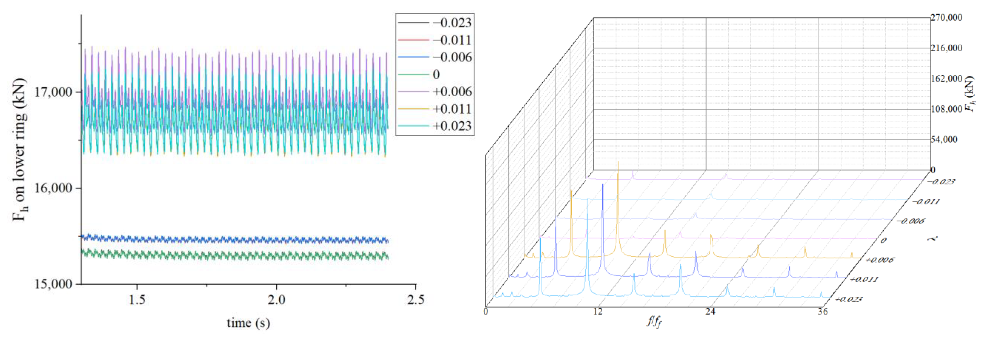
As shown in
Figure 14, taking the vertical upward direction as positive, the axial water thrust on the lower ring is positive. When the gap thickness
λ of the upper crown is reduced by 0.006 and 0.011, the axial water thrust of the lower ring increases, and the axial force value is almost the same. When
λ is reduced by 0.023, the axial water thrust of the lower ring has almost no change compared with the initial thickness. The axial water thrust on the lower ring also increases when
λ is increased, and the axial water thrust on the lower ring is larger when the value is increased by 0.006 compared to increases of 0.011 and 0.023. By increasing the gap thickness of the upper crown, the main frequency of the axial water thrust on the lower ring is 10
ff, and the secondary frequency is 15
ff.
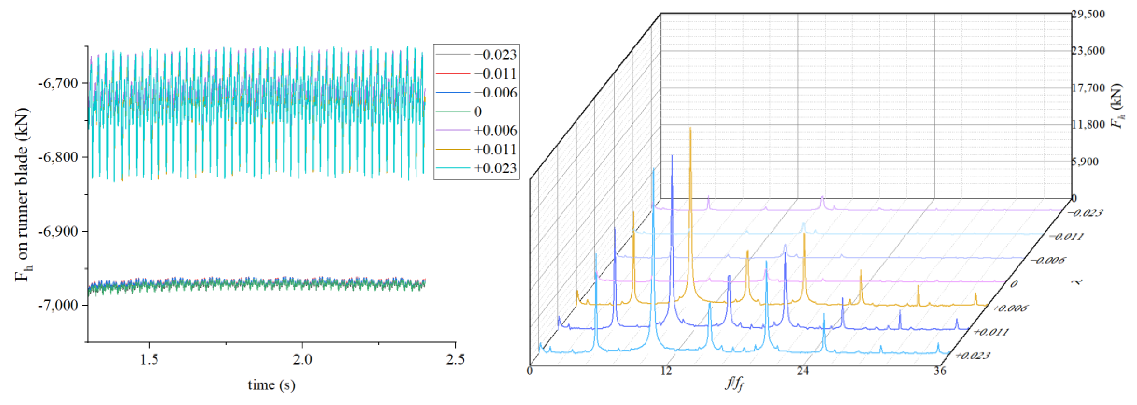
The axial water thrust on the suction surface and pressure surface of the blade is shown in
Figure 15, and the fluctuation of the axial water thrust on the blade is the largest when the increase is 0.023. Reducing the crown gap thickness has little effect on the axial water thrust of the blade. By increasing the crown gap thickness, the primary frequency of the axial water thrust on the blade is 10
ff, and the secondary frequency is 15
ff.
The resultant force of the axial water thrust on the runner is shown in
Figure 16. When the thickness of the upper crown gap is reduced, the resultant force of the axial water thrust decreases to about 77 kN, but the value of the resultant force increases slightly when it decreases to 0.023. When the thickness of the upper crown gap is increased, the axial water thrust increases greatly, and the resultant force increases the most when it increases by 0.011, which is about 3828 kN. By increasing the crown gap thickness, the main frequency of the resultant axial water thrust on the runner is 10
ff, and the secondary frequency is 15
ff.
The results show that increasing or decreasing the thickness of the upper crown gap can effectively change the axial water thrust and the resultant force of the axial water thrust on the upper crown and lower ring. However, the axial water thrust on the blade is only sensitive to increases in the thickness of the upper crown gap, and reducing the thickness hardly changes the axial water thrust on the blade. Increasing the thickness of the upper crown gap has a greater impact on the resultant axial hydraulic thrust compared to reducing the thickness of the upper crown gap. The thickness of the upper crown gap only increases by 0.006, and the average value of the resultant axial hydraulic thrust increases by about 3240 kN compared with the original gap thickness. Decreasing the thickness of the upper crown gap can reduce the axial water thrust. When the gap thickness λ of the upper crown is increased, the value of the axial water thrust and the resultant force of the axial water thrust on the upper crown, the lower ring and the blade increases greatly, and the pulsation frequency also increases significantly. The water thrust changes periodically with time, with a main frequency of 10 ff and a secondary frequency of 15 ff. When the gap thickness of the upper crown is reduced, the overall change in the axial water thrust and the resultant force of the axial water thrust on the upper crown, lower ring and blade is relatively stable. The effect of reducing λ by 0.006 and 0.011 is similar, but reducing it by 0.023 slightly increases the resultant force of the axial water thrust.


 ,
, 


