Article

Tracking Multiphase Flows through Steep Reservoirs with External Constraint

1
Department of Mathematics, Institute of Arts and Sciences, Government College University Faisalabad, Chiniot Campus, Chiniot 35400, Pakistan
2
Section of Environmental Fluid Mechanics, Department of Hydraulic Engineering, Faculty of Civil Engineering and Geosciences, Delft University of Technology, Stevinweg 1, 2826 CN Delft, The Netherlands
3
Department of Mathematical Sciences (FBAS), Balochistan University of Information Technology, Engineering and Management Sciences, Quetta 87300, Pakistan
*
Author to whom correspondence should be addressed.
Water 2023, 15(18), 3300; https://doi.org/10.3390/w15183300
Submission received: 19 August 2023 / Revised: 10 September 2023 / Accepted: 17 September 2023 / Published: 19 September 2023

Abstract

:
Problem statement: The study offers theoretical formulations for high-viscosity particulate flows in inclined reservoirs, taking into account the presence of homogeneous spheroidal particles of various types to produce discrete two-phase suspensions. Purpose: The primary objective of this analytical and comparative study is to identify the most dependable nanoparticles among hafnium and crystal metals that are suspended in an Eyring–Powell fluid through an inclined channel while being subjected to external magnetic and gravitational forces. Solution methodology: The flow dynamics of multiphase flows are formulated utilizing the stress tensor of the base fluid. The regular perturbation method (RPM) is employed to attain a more closed-form solution. The perturbation method is frequently employed in engineering problems to obtain an approximated solution, even when demonstrating the convergence of the solution is challenging. The rough solution is also validated through a thorough parametric analysis that shows the role of relevant parameters that contribute to the multiphase flow. Results: A concise parametric study is carried out against some of the most pertinent parameters and reveals that additional particles have promising effects on the momentum of each multiphase flow, whereas Eyring–Powell multiphase suspensions lessen in momentum due to strong internal viscous forces. The velocity of fluid and particle phases diminish with Hartmann number M and Froude number Fr. The second-order material constant B and concentration of nanoparticles C boost the motion of the fluid. The velocities of the particulate phase are quicker than the fluid phase. The hafnium particle is more reliable than crystal particles. Solution benchmark: Numerical and graphical findings have also been compared with the existing literature for the limiting case and found to be fully in agreement. Applications: This study’s findings provide a wider understanding of subterranean flows, specifically within the petroleum sector, with a focus on multiphase flows. Originality: The current study represents the authors’ original work and has not been previously submitted or published elsewhere.

1. Introduction

The flow of non-Newtonian fluids plays a crucial role in various industries, including biology, chemistry, medicine, oil, and pharmaceuticals, due to the complex tensor deformation relationship. Non-Newtonian fluids are also widely utilized in engineering and technology, such as food clarification, biological liquid motion, lubricant production, and plastic manufacturing. Several non-Newtonian models have been proposed by authors and researchers to gain insight into the rheological behavior of non-Newtonian fluids, such as third-grade fluids, fourth-grade fluids, Jeffrey fluids, Maxwell fluids, Williamson fluids, Phan-Thien–Tanner (PTT) fluids, power-law fluids, Rabinowitsch fluids, and couple stress fluids. Technical terms will be explained upon their first mention. Tangent-hyperbolic, Ellis, Casson, Oldroyed-B, Carreau–Yasuda, Reiner–Philippoff, Sisko, micropolar, Prandtl, Johnson–Segalman, Burgers, modified Burgers, Cross, Bingham plastic, Sutterby, and Eyring–Powell fluids are all examples of non-Newtonian fluids. The Eyring–Powell fluid model was initially introduced by Eyring and Powell [1] in 1944. This flow model is formulated mathematically using the kinetic theory of liquids, rather than relying on empirical data. Eyring–Powell fluid has significant applications in fields such as industry, biological technology, and manufacturing processes. With these various applications in mind, the authors have conducted several studies to demonstrate the significance of this model. Ali et al. [2] discussed non-Newtonian fluid flow through a pipe using a numerical and semi-analytical approach. They also explored non-uniform temperature-dependent viscosity models through a comparative analysis between numerical and semi-analytical solutions. Nazeer et al. [3] applied Eyring–Powell fluid through a pipe using the finite difference and perturbation methods, selecting the space-dependent viscosity model. The authors determined the validity of the perturbation solution for small perturbation parameter values. Bhattacharyya and colleagues [4] investigated the impact of Joule heating on the flow of Eyring–Powell fluid in uniform and non-uniform channels with flexible walls. Their findings demonstrate that the temperature distribution is increased by the Joule heating parameter. Khan et al. [5] investigated the impact of an irregular heat source on Eyring–Powell fluid flow with suspended nanoparticles through numerical analysis. Additionally, they presented the application of Eyring–Powell fluid in wire coating through numerical simulation in a previous study [6].
The study of fluid–particle suspensions in two-phase flows has significant applications in areas such as power plant pipework, transportation of petroleum, vehicle exhaust emissions, blood circulation, corrosive particles in engine oil flow, mining, and more. The analysis of particle contact with solid or liquid body boundaries has attracted considerable interest from authors and researchers. For example, Ellahi et al. [7] studied the flow of multiphase suspensions containing two types of nanoparticles (silver and gold) in a thin-film analysis. Their computational results showed that silver nanoparticles are the most effective option for improving coating processes. The electrokinetic effect in multiphase flow using various shapes of configuration was analyzed by Hussain et al. [8], whilst the analysis of heat transfer in an elastic pipeline that considered multiphase flow was examined by Zhang et al. [9]. Important applications of multiphase flow through the transport of porous medium were presented by Jiang et al. [10] and Al Kubaisy et al. [11]. The study by Bhatti et al. [12] examined the peristaltic motion of fluid–particle phases flowing through a tube with slip boundary conditions, focusing on suspending rigid spherical particles in a non-Newtonian fluid. Using MATEMATICA software 12.0, they derived an algorithm that obtained an exact solution to the problem. The analysis showed that a reduction in particle concentration leads to a decrease in pressure gradient and supports the pressure-rise profile. A study by Abdelsalam and Zaher [13] investigated the heat transfer analysis of Rabinowitsch fluid suspension flowing through a vertical channel experiencing peristaltic waves. The study also took into account constant heat source and electrokinetic forces. First, the authors derived the precise solution to the problem and analyzed the graphical properties of the velocity field, pressure gradient, pressure increase, temperature distribution, and shear stress based on the physical parameters of the study. They then highlighted the practical uses of fluid–particle suspensions in pathological blood with various volume fractions of spherical nanoparticles. Their computational findings indicated that the increase in volume fraction led to an improvement in both axial velocity and shear stress.
The resulting fluid is known as a nanofluid when nanoparticles are suspended in a conventional fluid, such as water, which typically has low thermal conductivity. Nanofluids have gained significant attention from researchers lately due to their wide range of numerical and experimental applications in various engineering problems. He et al. [14] suspended zinc oxide and silver nanoparticles in a water-based nanofluid in order to determine the optimum neuron number, performance and correlation coefficient when using an artificial neural network. The surface fitting method and artificial neural networks were utilized, and it was determined that the surface first agent yielded less error than the second agent. Yan et al. [15] conducted experimental work on a hybrid nanofluid to evaluate the rheological properties of a non-Newtonian fluid. Unyong et al. [16] describe the application of heat transfer rate and entropy generation analyses in hybrid nanofluid over stretching sheets using an analytical approach. Their results indicate an improvement in heat conduction ability with increased values of hybrid nanoparticles. In a numerical technique study, Bhatti et al. [17] report on the use of cobalt oxide and graphene nanoparticles in thermal solar storage systems. The successive linearization method was used to simplify the given system, which was subsequently solved using the Chebyshev spectral method. The results obtained by the researchers indicate that motion of fluid particles is reduced by cobalt oxide nanoparticles, leading to a diminished velocity distribution. In [18], Bhatti and colleagues studied the potential applications of hybrid nanofluids through vertical parallel plates utilizing gold and magnesium oxide nanoparticles suspended in third-grade fluid. Riaz and colleagues [19] conducted an analysis of nanoparticle application within peristaltic motion, taking into account porous medium effects. Awan et al. [20] and Saleem et al. [21] presented research on the application of nanoparticles in the Ellis fluid model, highlighting improved heat transfer analysis when using nanoparticle suspensions. Vidya et al. [22] discussed the effects of suction and injection on entropy generation within a tilted channel. The Hermite wavelet method was employed to solve a system of coupled equations, yielding solutions for velocity, temperature, entropy generation and the Bejan number. The conclusion drawn was that entropy generation increased with Casson fluid parameter. The results were validated using alternative methods, with a notable correlation observed. Noreen et al. [23] analyzed the heat transfer characteristics of Carreau fluid in a tilted asymmetric channel, taking into account viscous dissipation. They derived the analytical solution using the perturbation method, concluding that the pressure gradient increases with the inclination angle.
The specific gravity of a fluid or substance is a pivotal parameter denoting the ratio of its density relative to that of a specified reference substance, commonly water. While gravity perpetually exerts its influence on the natural flow of fluids, it is essential to recognize that this force is not a static constant, but rather a variable that fluctuates across different locations. These gravitational variations have substantial implications, leading to notable fluctuations in various mass-related parameters within the intricate domain of hydraulic models. Gravity, an omnipresent force, exerts its effects whenever fluids are set in motion, whether they traverse the vertical axis or navigate along inclined paths along the horizontal axis. Numerous diligent researchers have embarked on a quest to unravel the multifaceted influence of gravity on fluid dynamics. A case in point is the study undertaken by Li et al. [24], which delves deeply into a challenging and often misconstrued factor related to the structural resilience of steel shear walls under the influence of gravitational forces. In a separate but equally enlightening endeavor, Song et al. [25] developed a numerical model to decipher critical angle governing pipelines, a crucial investigation geared towards mitigating undesired water accumulation within pipes conveying oil–water fluids. Simultaneously, Nazeer et al. [26] embarked on a scientific exploration employing a semi-analytical technique to delve into the intricate realm of multiphase flow applications. Their computational findings unveiled a compelling revelation that the suspension of Hafnium nanoparticles exhibits superior suitability for nuclear reactor applications when compared to crystal nanoparticles. This insight is of profound significance in the realms of materials science and engineering.
The scientific domain of magnetohydrodynamic (MHD) studies the motion of electrically conducting fluids through channels, conduits, and pipes. This area of research is relevant to diverse fields, including geophysics, nuclear reactors, blood flow measurement, and accelerators. The foundational work on MHD flow through parallel walls was conducted by Hartmann [27], who laid the groundwork for numerous MHD devices. After conducting their analysis, the researchers and scientists advanced the field of magnetohydrodynamics in various areas. They presented the application in different contexts, including the numerical investigation of chemically reactive nanofluid flow over a permeable stretching sheet by Maheswari et al. [28]. Turabi et al. [29] examined the problem of MHD nanofluid flow through multiple layers. They obtained a semi-analytical solution to their problem using the homotopy analysis method. They divided the problem’s geometry into two regions. Region I contains the titanium oxide nanoparticles, while graphene-titanium oxide nanoparticles are added in region II. The magnetic parameter has a similar effect on velocity and thermal profiles according to their findings. Recently, Nazeer et al. [30] presented the application of magnetic fields in cavity flow problems using the Galerkin finite element method as a numerical scheme. The authors simulated the nonlinear boundary value problem and calculated the numerical computational results. Technical term abbreviations, such as Galerkin finite element method, were explained upon first use. Their computational findings demonstrated that in the cavity, without considering thermal radiation, the aluminum alloy nanoparticles offer the most favorable cooling. However, with the inclusion of the effects of radiation, the titanium alloy exhibits a faster cooling process than the aluminum alloy. In their study, Saha et al. [31] utilized numerical techniques to report the implementation of a magnetic field in the flow of nanofluid through a thermally heated wavy cavity. The researchers employed the weighted residual Galerkin finite element method to solve their mathematical model and produce the streamlines and isotherm contours. Their numerical findings indicated that the thermal transport rate was raised by 7.65% with blade-shaped nanoparticles, as opposed to the spherical ones, with only 2.86%.
The primary aim of this analytical and comparative study is to identify the most trustworthy nanoparticles suspended in an Eyring–Powell fluid in an inclined channel under the effects of external magnetic and gravitational forces. The study is a novel one and has not been conducted previously. The governing equations are expressed as nonlinear boundary value problems and subsequently simplified using non-dimensional variables. Then, the system of equations is solved analytically and presented as the analytical solution. The effect of the parameters on the flow field is portrayed through graphical representation, which is created using Mathematica software 12.0. The study is formulated in the following way. Section 1 provides an overview of non-Newtonian fluids, including their particle suspensions, responses to gravity, electrically conducting flows, and relevant research studies. Section 2 presents the mathematical formulation of the problem, while Section 3 introduces the dimensionless quantities and dimensions. Section 4 presents the methodology used to solve the problem, while Section 5 provides a physical interpretation of the parameters with regard to important physical quantities. Section 6 benchmarks the solution, and Section 7 offers concluding remarks.

2. Mathematical Modeling

Consider the two-phase flow of Eyring–Powell fluid through inclined infinite plates of distance 2 L as depicted in Figure 1. The hafnium and crystal nanoparticles (red solid circles shown in Figure 1), each with uniform size, are suspended in the base fluid, an Eyring–Powell fluid, in quantities of up to 40%. It is assumed that no slip occurs between the base fluid and nanoparticles. The upper plate is set at y = L , the lower plate is fixed at y = L , and fluid is flowing in x-axis direction. The upper and lower plates are stationary, i.e., u f y = L = 0 and u f y = L = 0 . The fluid is electrically conducting and incompatible, and a homogeneous magnetic field B 0 is applied in a positive y-axis direction and assumed to be one direction as the induced magnetic field is neglected by using the assumption of low magnetic Reynolds number. The channel has an inclination angle of α .
Given the equation of conservation of mass and Navier–Stokes equation for the conservation of momentum, one can easily yield the following:

2.1. Governing Equations for Fluid Phase

The governing equations for the fluid phase are given as [32,33].
. V f = 0 ,
ρ f ( 1 C ) D   V f D   t = ( 1 C ) p + ( 1 C ) S S C ( V p V f ) + J × B + g ρ f .
In the above equation, S ” denotes the non-Newtonian fluid stress tensor [34].
S = [ μ s + 1 k 2 sinh 1 ( k 3 ψ ˙ ) ψ ˙ ] A 1 ,
ψ ˙ = 1 2 t r a c e ( A 1 ) 2 ,
sinh 1 ( k 3 ψ ˙ ) = k 3 ψ ˙ 1 3 ! ( k 3 ψ ˙ ) 3 .
In the above equations, the density number is denoted by C , J is the current vector, B is known as applied uniform magnetic force, S is the drag force, p is the pressure, t is the time, D D t is a material derivative, S is a stress tensor of an Eyring–Powell fluid, g is gravitational acceleration, ρ f is called the density of the fluid, μ s is the viscosity, k 2 and k 3 refer to material constants of an Eyring–Powell fluid, A 1 denotes the Rivlin–Ericksen tensor, and V f , p are used to describe the fluid and particle phase velocity distribution.

2.2. Governing Equations for the Particle Phase

The governing equations for the particle phase are defined as:
. V p = 0 ,
ρ p C D   V p D   t = C p + S C ( V p V f ) + g ρ p .
It is assumed that the fluid and particle phases are initially in a stationary position and the density of the particles is constant throughout the flow analysis. This means that no further particles are added or removed during the flow analysis. V f = [ u f x , y , 0,0 ] and V p = [ u p x , y , 0,0 ] denote the motion of the fluid and solid phases, respectively. Then, the above equations are reduced into the following:
u f x + v f y = 0 ,
ρ f ( 1 C ) ( u f t + u f u f x + v f u f y ) = ( 1 C ) p x + ( 1 C ) { μ s ( 2 u f y 2 ) + A ( 2 u f y 2 ) B 2 ( u f y ) 2 ( 2 u f y 2 ) } S C ( u p u f ) σ B 0 2 u f + g ρ f sin α ,
u p x + v p y = 0 ,
ρ p C ( u p t + u p u p x + v p u p y ) = C p x + S C ( u p u f ) + g ρ p sin α .
Employing the assumption of no-slip boundary conditions:
u f ( ± L ) = 0 .

3. Solution to the Problem

Introducing the following list of quantities in (8)–(12) to analyze the contribution of the most prominent variables, defined as:
X ¯ = x L ,   Y ¯ = y L ,   u ¯ f = u f u ,   u ¯ p = u p u ,   g = g g , F r = u L g ,   ρ r e l = ρ f ρ p ,   p ¯ = p L u μ s ,   M = B o L σ μ s . }
Ignoring the bar signs, it is obtained.
2 u f Y 2 + A μ s 2 u f Y 2 B 2 μ s ( u f Y ) 2 ( 2 u f Y 2 ) M 2 ( 1 C ) u f + ( n 1 + n 3 n 1 n 3 ) g sin α ( 1 C ) ( F r ) 2 1 ( 1 C ) p X = 0 ,
Since the main cause of the present flow analysis is a gravitational force in the inclined channel. Therefore, the role of pressure is considered uniform throughout the channel. As such, we take P = p X , then Equation (14) can be written as:
2 u f Y 2 + A μ s 2 u f Y 2 B 2 μ s ( u f Y ) 2 ( 2 u f Y 2 ) M 2 ( 1 C ) u f + ( n 1 + n 3 n 1 n 3 ) g sin α ( 1 C ) ( F r ) 2 P ( 1 C ) = 0 ,
u p = u f n 2 n 3 C ( F r ) 2 P + n 2 g sin α C ( F r ) 2 n 3 ,
u f ( ± 1 ) = 0 .

4. Approximate Analytical Technique

The intricate description of the two-phase flow phenomenon involving a non-Newtonian fluid is marked by its pronounced nonlinearity, as explicitly demonstrated in Equation (14). This inherent nonlinearity presents a formidable analytical challenge, making it a complex subject for conventional analytical analysis. Consequently, in pursuit of a robust solution to this intricate problem, the esteemed “perturbation method”, a well-established semi-analytical technique, has been judiciously invoked, as referenced in [35]. The perturbation method, a venerable tool in the arsenal of engineering problem-solving, has emerged as a stalwart ally in situations where analytical solutions prove elusive due to the intricate nature of the underlying equations. This method, renowned for its versatility, excels in scenarios where the convergence of the solution may not be readily demonstrable, as noted in [36]. It offers a distinctive advantage over alternative techniques, primarily owing to its economy in computational resources. This method’s computational demands are notably modest, rendering it accessible even on less powerful computing platforms, without necessitating additional computational resources or specialized hardware. Thus, the perturbation method stands as a prudent choice for tackling the intricate intricacies of non-Newtonian fluid dynamics in the context of two-phase flows, exemplifying the resourcefulness and adaptability of engineering problem-solving techniques.
Therefore, it is considered that
u f = u f o + ε u f 1 + o ( ε 2 ) ,
be the required perturbed solution to Equation (15), such that
B = λ ε .
In the above equations, ε is termed a “perturbed parameter”, which assists in formulating the zero-order and first-order problems, respectively, as given below.
ε o :    2 u f o Y 2 + A μ s 2 u f o Y 2 M 2 u f o ( 1 C ) + ( n 1 + n 3 n 1 n 3 ) g sin α ( 1 C ) ( F r ) 2 P ( 1 C ) = 0 ,
u f o ( ± 1 ) = 0 .
Similarly,
ε 1 :    2 u f 1 Y 2 + A μ s 2 u f 1 Y 2 λ 2 μ s ( u f o Y ) 2 ( 2 u f o Y 2 ) M 2 u f 1 ( 1 C ) = 0 ,
u f 1 ( ± 1 ) = 0 .
Solving Equations (20) and (22) subject to the boundary conditions (23), one yields:
u f o = m 4 + m 5 cosh [ Y m 3 ] + m 6 sinh [ Y m 3 ] ,
u f 1 = λ ( cosh [ Y m 3 ] ( m 7 + m 8 cosh [ 2 Y m 3 ] ) + sinh [ Y m 3 ] ( m 9 + m 10 cosh [ 2 Y m 3 ] ) ) .
Using (24) and (25) in (18) provides the flow dynamics of the fluid phase.
u f = ( m 4 + m 5 cosh [ Y m 3 ] + m 6 sinh [ Y m 3 ] ) + B ( cosh [ Y m 3 ] ( m 7 + m 8 cosh [ 2 Y m 3 ] ) + sinh [ Y m 3 ] ( m 9 + m 10 cosh [ 2 Y m 3 ] ) ) .
Similarly, we can get the expression for the velocity of the particulate phase u p .
u p = ( m 4 + m 5 cosh [ Y m 3 ] + m 6 sinh [ Y m 3 ] ) + B ( cosh [ Y m 3 ] ( m 7 + m 8 cosh [ 2 Y m 3 ] ) + sinh [ Y m 3 ] ( m 9 + m 10 cosh [ 2 Y m 3 ] ) )           C n 2 ( n 3 ( F r ) 2 P g sin α ) C n 3 ( F r ) 2 .
In the above m 1 ,   m 2 and m 3 are constants defined in Appendix A.

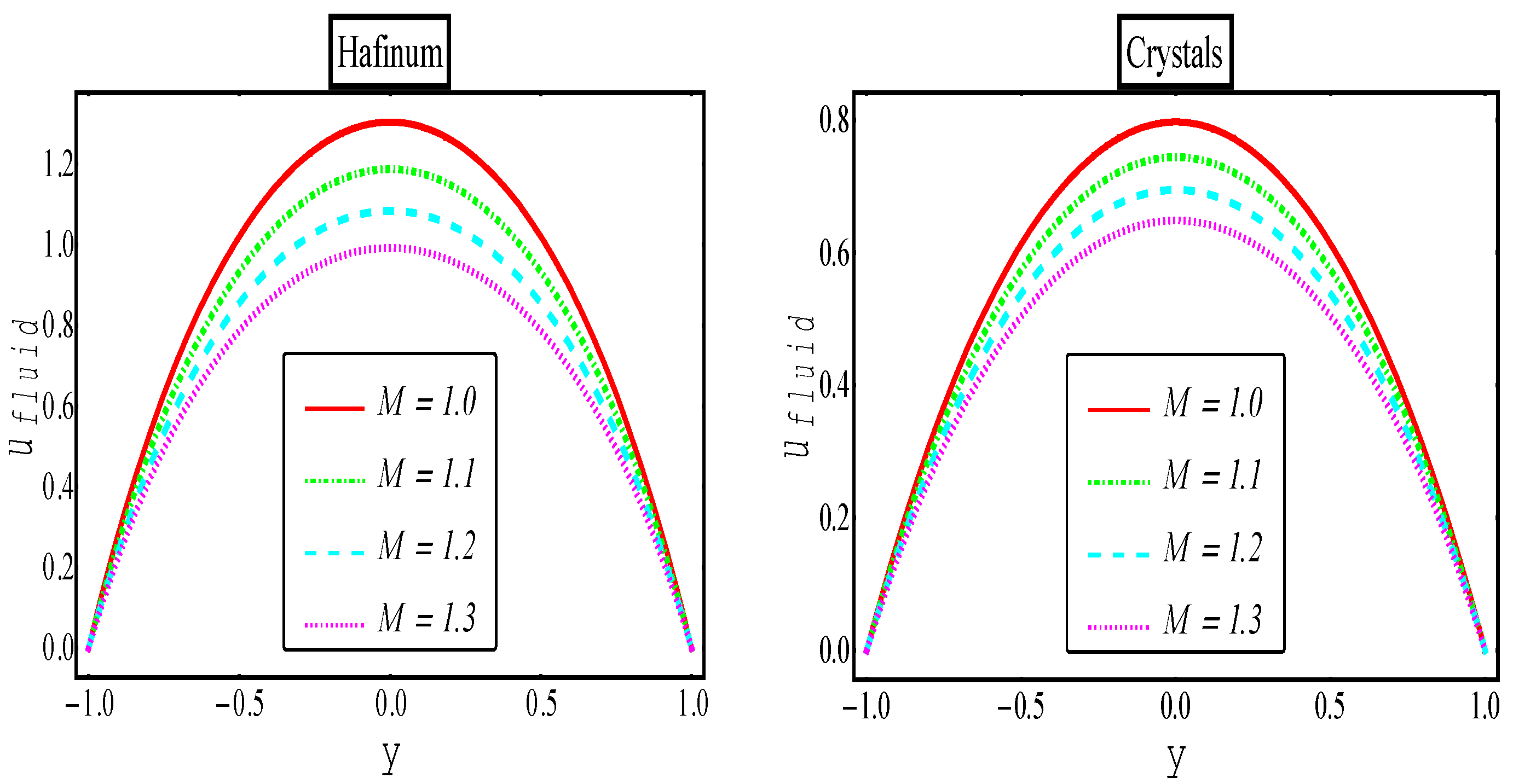
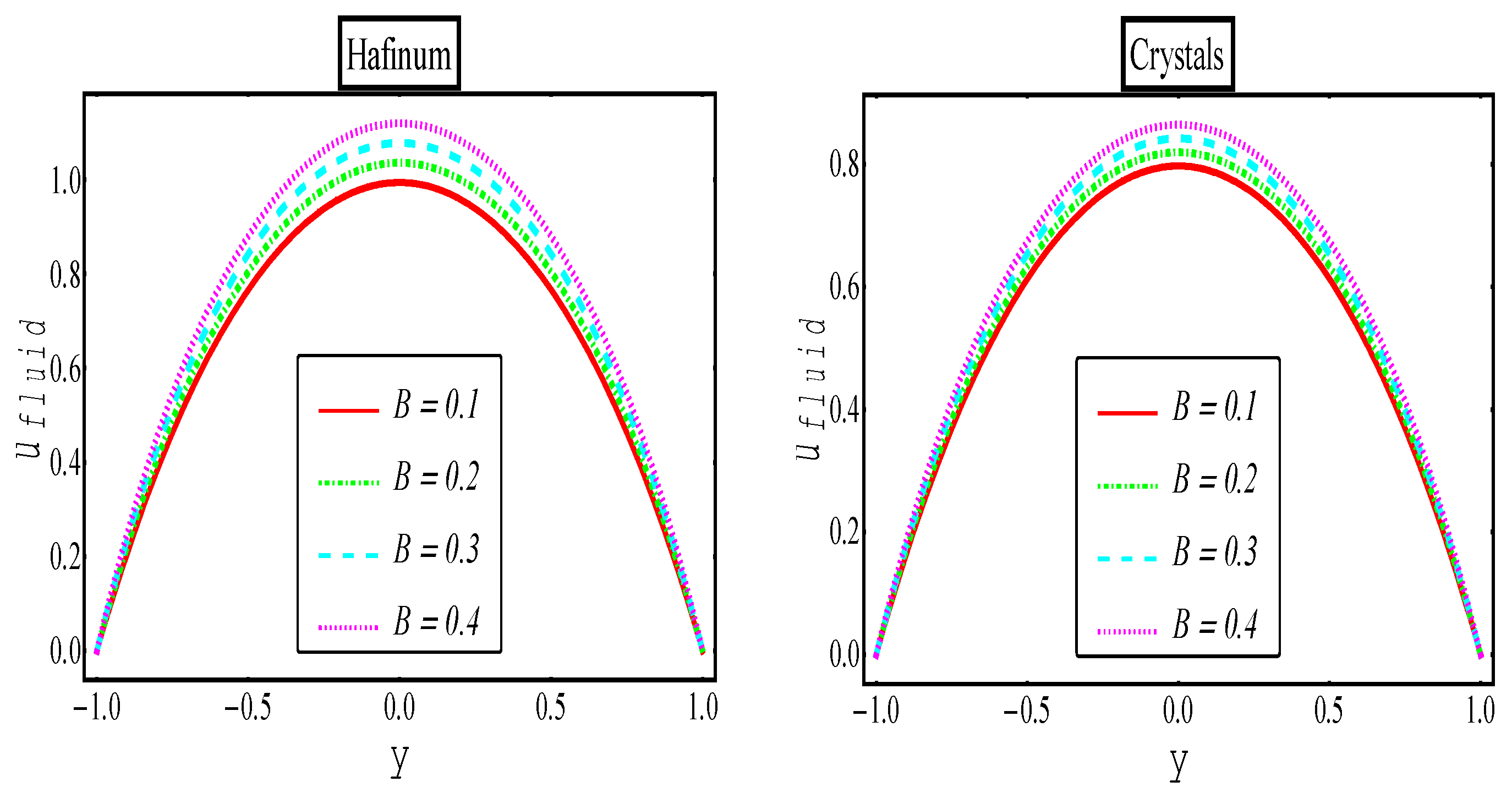
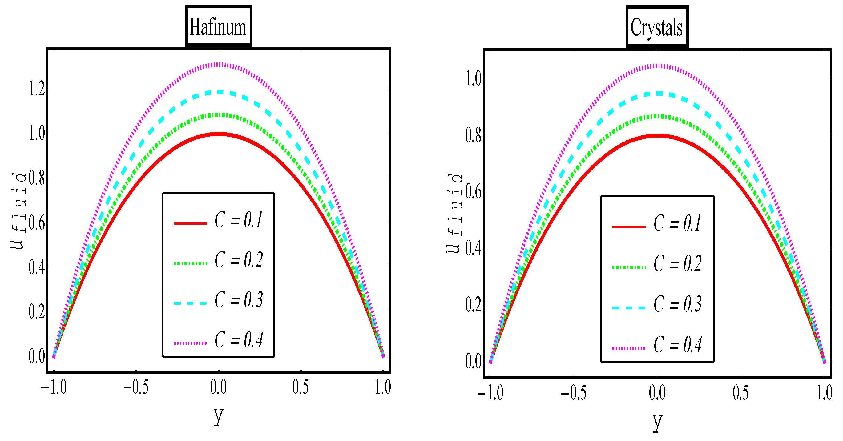
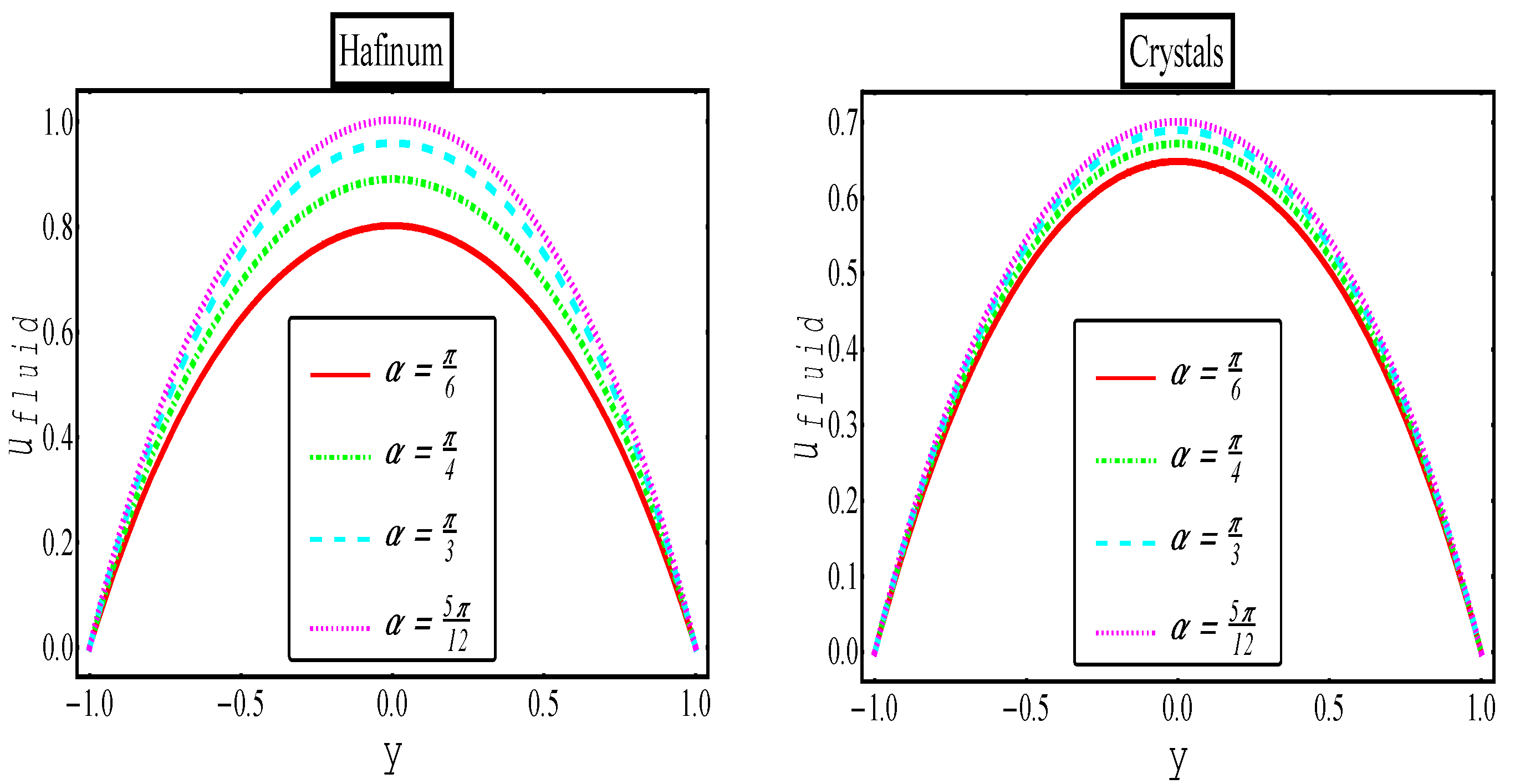
5. Results and Discussion

Various theoretical formulations have been meticulously developed to comprehensively investigate the intricate dynamics governing the flow of exceptionally high-viscosity particulate matter through an inclined reservoir. These innovative formulations are designed to encapsulate the behavior of spherically homogeneous particles, each exhibiting unique characteristics that interplay to create discernible two-phase suspensions within the system. Employing a sophisticated semi-analytical methodology, these formulations enable an in-depth analysis of multiphase flows subjected to the compelling influence of externally applied magnetic fields. Theoretical formulations have been developed for the flow of highly viscous particulate matter through an inclined reservoir. The formulations consider spherically homogeneous particles of different types that combine to form distinct two-phase suspensions. A semi-analytical technique is employed to analyze multiphase flows under the influence of applied magnetic fields. In the final section, a semi-analytical solution is presented. The section includes a parametric study illustrated with graphs. The parameters under study are A, the material constant of order one; B, the material constant of order two; M, the Hartmann number; Fr, the Froude number; C, the particle concentration; and α, the inclination angle.
In Figure 2, Figure 3, Figure 4, Figure 5, Figure 6 and Figure 7, objective evaluations have been captured regarding the momentum of Eyring–Powell multiphase flows against pivotal parameters. Figure 2 illustrates the impact of the Hartmann number on the velocity distribution with both nanometallic particles. Stronger magnetic fields induce strong Lorentz forces, which repel the two-phase flow. Therefore, the velocity of Eyring–Powell multiphase fluid decreases as the Hartmann number increases. Nonetheless, the momentum of the multiphase suspension is noticeably higher when metallic particles are used compared to crystal particles. Figure 3 outlines the effect of material parameter “A” on the fluid phase, demonstrating a decrease in the momentum of the fluid phase suspension. The impact of the Froude number on the fluid phase is illustrated in Figure 4. Variability in the dimensionless quantity also opposes the motion of the two-phase liquid. It can be inferred that the influence of gravitational effects on the oblique flow decreases gradually during the flow. Figure 5 illustrates the effect of the second-order material parameter B on fluid velocity distribution in the presence of dual nanoparticles. The graphs demonstrate that the second-order material parameter B improves the velocity profiles of both suspensions. Figure 6 illustrates the varying contributions of different particle types towards the speed of base liquids flowing through an inclined channel. Increasing the number of particles further enhances the velocity of the liquid. The inclination of the steep channel constitutes the most significant parameter of the study. In Figure 7, the angle of inclination “α” is gradually altered; the faster the motion of the fluid phase for both types of particles, the steeper the incline.

6. Comparative Analysis

Comparative analysis is crucial for verifying the accuracy of computed results. To that end, we have included a section that outlines the benchmarking of our solution against previously published results.

6.1. Current Study vs. a Previous Study

This section of the study presents a comparison between the current and previously published computational findings by Zeeshan et al. [37]. To achieve this objective, Figure 8 validates the results of the liming case, wherein a Newtonian fluid is suspended with the same particle studied in this computational analysis. Zeeshan et al. [37] studied the biphasic flow of Newtonian fluid suspended with hafnium and crystal particles through an inclined channel, including the effects of a magnetic field. In this context, the present study is validated for the limit when the non-Newtonian fluid parameter A = B → 0. Figure 8 presents a comparative analysis with respect to the magnetic field parameter. The solid lines illustrate the variation in the magnetic field for the Eyring–Powell fluid, which is in complete harmony with the previous investigation conducted in [37], represented by dots.

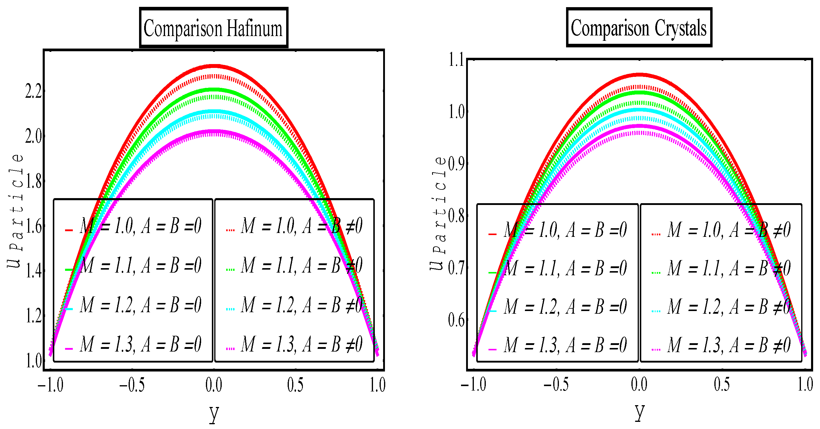
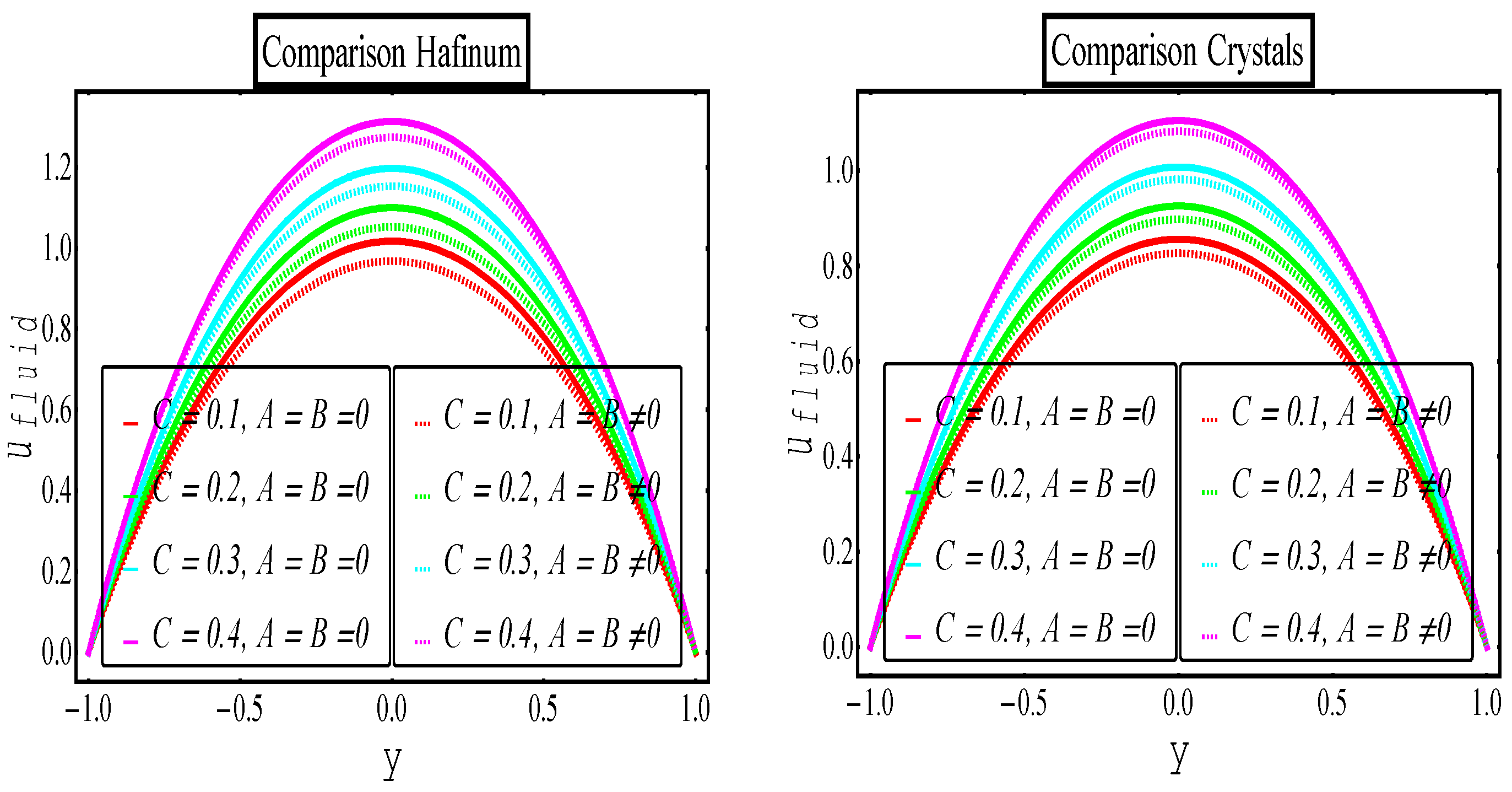
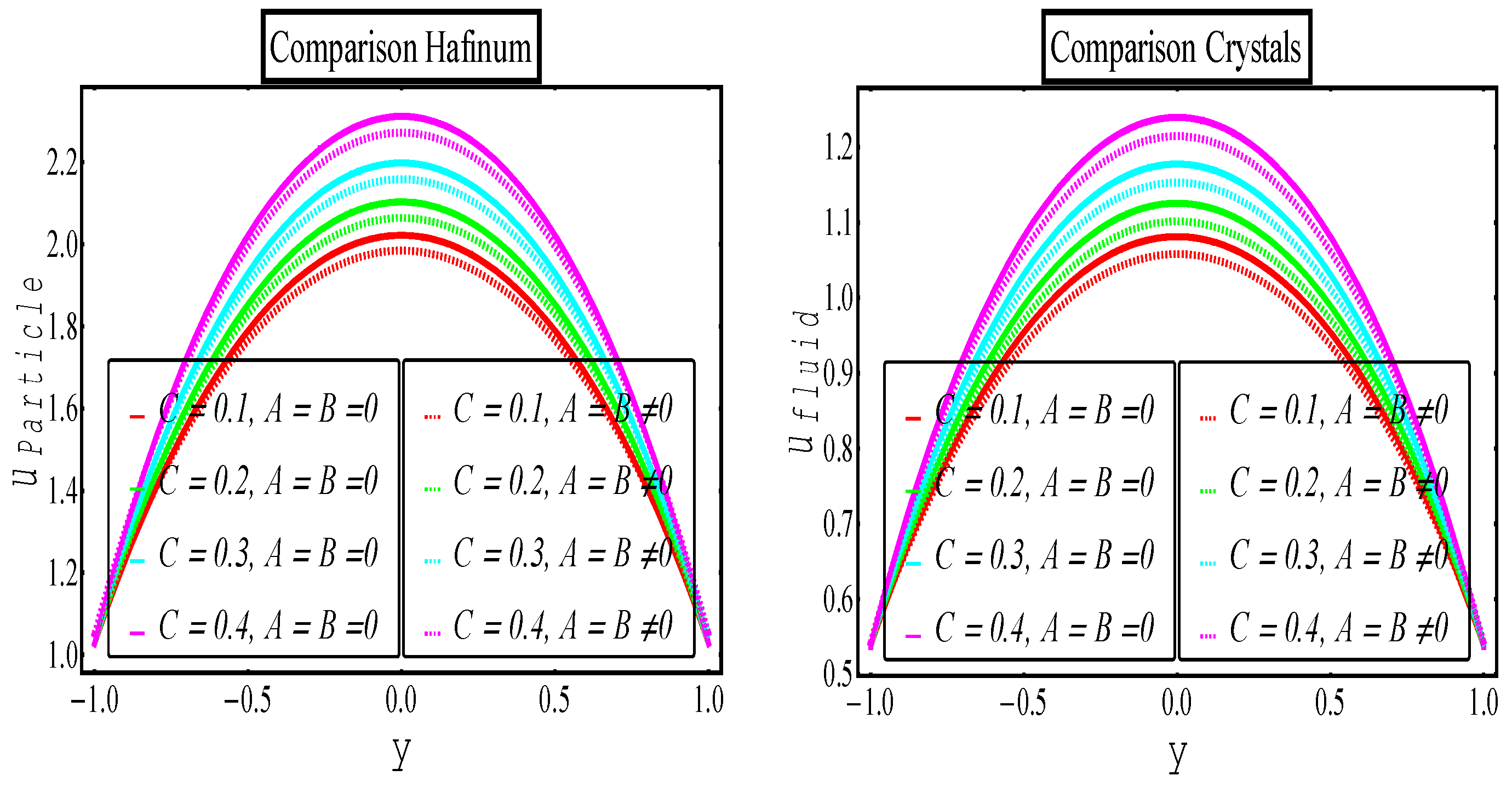
6.2. Eyring–Powell Multiphase vs. Newtonian Multiphase

Within this section of the article, we embark upon a comprehensive comparative analysis between two distinct classes of multiphase suspensions: the Eyring–Powell multiphase suspensions and their Newtonian counterparts. This analytical journey unfolds visually through the elucidating depictions presented in Figure 9, Figure 10, Figure 11 and Figure 12, each of which provides invaluable insights into the intricate interplay of various parameters. The nexus between these suspensions is established by delving into the variations of two pivotal parameters, namely, the Hartmann number, denoted as “M”, and the particle concentration, represented by “C”. It is worth highlighting that the particulate phase within these multiphase suspensions encompasses a rich diversity of nanospecies comprising metallic and crystal components of distinct characteristics and properties. In our visual representations, we employ a deliberate symbolism: the Eyring–Powell multiphase suspensions are artfully depicted using dotted sketches, while their Newtonian counterparts take form as solid, tangible graphs. Beginning our exploration with Figure 9, keen observers will discern a discernible trend. Here, the velocity of Eyring–Powell multiphase suspensions is clearly observed to exhibit a decrease when subjected to the influence of robust magnetic fields, a phenomenon that aligns with prior discussions within this article. However, our narrative transcends this initial observation. As we progress through Figure 10, Figure 11 and Figure 12, a more intricate and multifaceted picture emerges. It becomes evident that the viscous effects within Eyring–Powell multiphase suspensions wield a substantial influence, surpassing those experienced within Newtonian multiphase suspensions. This nuanced difference in viscous effects manifests as a hindrance to the flow dynamics, effectively impeding the fluid’s progress—a captivating revelation brought to life through the illustrative power of Figure 10, Figure 11 and Figure 12.

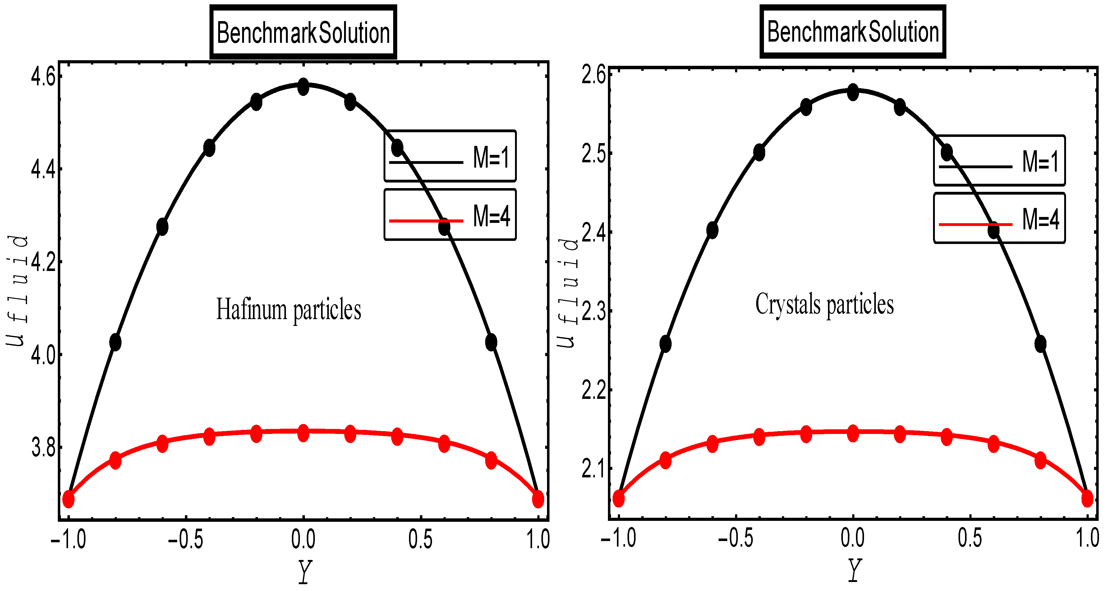
6.3. Computational Validation

Numerical data have been computed in Table 1, Table 2, Table 3 and Table 4 against relevant parameters. Technical abbreviations are explained when first used. The findings of multiphase flows suspended with metallic and crystal particles have been compared with Newtonian multiphase flows for the limiting case. Table 1 presents numerical data for multiphase flow suspensions containing metallic particles against the variation in magnetic fields and the number density of the particles. One can observe a reduction in the momentum of fluid under stronger magnetic fields, whereas the addition of metallic particles enhances the momentum in multiphase flow. A similar trend is evident in the flow dynamics of the Newtonian two-phase flow. Table 2 offers considerations for crystal particles in two-phase suspensions. The fundamental characteristics of multiphase flows remain consistent for both Newtonian and non-Newtonian fluid flows. However, the suspensions produced from metallic particles exhibit greater momentum than those formed with crystal particles. Table 3 and Table 4 present the numerical data on the impact of the Froude number and the inclination of the inclined channel. The velocity of the base liquids decreases as the dimensionless quantity Fr increases, while a reverse trend is evident in the momentum of the base fluid for higher inclinations.

7. Concluding Remarks

Within the realm of theoretical exploration, this study delves comprehensively into the intricate dynamics governing multiphase flows of a non-Newtonian fluid. The primary focus of this theoretical analysis centers on the nuanced examination of two-phase flows transpiring within an inclined channel, all while adhering to specific constraints meticulously defined in our research framework. To emulate the conditions of a suspension, we thoughtfully introduced spherical, uniformly distributed solid nanoparticles, namely, hafnium and crystal, into the foundational fluid—an Eyring–Powell fluid, characterized by its distinctive rheological properties. The accurate representation of both the fluid and particle phases necessitated the formulation of intricate mathematical equations, which in turn were meticulously transformed into a set of nonlinear differential equations to capture the system’s intricacies. For the sake of clarity and ease of understanding, we dutifully elucidated and expanded upon the abbreviations associated with technical terminology whenever they were initially introduced, ensuring that our discourse remains accessible to a wide readership. The perturbation method, a venerable and well-established analytical approach renowned for its prowess in deriving analytical solutions to complex boundary value problems, was judiciously employed. Employing this method, we successfully unearthed explicit expressions that describe the behavior of both the fluid and particulate phases within our intricate system. A comprehensive parametric study, conducted with meticulous attention to detail explores the profound influence of various significant parameters and variables. This exhaustive investigation yielded a treasure trove of noteworthy findings, each possessing the potential to reshape our understanding of multiphase flows involving non-Newtonian fluids. To encapsulate the wealth of insights gleaned from this research endeavor, we present a succinct summary of our pivotal discoveries as follows:
The flow dynamics of multiphase suspensions are influenced by strong magnetic fields.
Promising results for the momentum of each flow can be achieved by adding extra particles.
Metallic suspensions produce better outcomes than those with crystals.
Theoretical and numerical findings were compared to an existing study for the limiting case and were found to be in good coherence.
The momentum of Eyring–Powell multiphase suspensions reduces due to their strong internal viscous forces.
The results of this study enhance our understanding of underground flows, specifically in the petroleum industry, with a particular focus on multiphase flows.

Author Contributions

Methodology, M.N. and F.H.; Software, F.H.; Formal analysis, M.N. and F.H.; Resources, W.A.; Writing—original draft, M.N.; Writing—review & editing, W.A. and F.H. All authors have read and agreed to the published version of the manuscript.

Funding

This research received no external funding.

Data Availability Statement

All authors are agreed to published this research in this journal.

Conflicts of Interest

The authors declare no conflict of interest related to this research.

Nomenclature

S Stress tensor N m 2 D D t Material time derivative
V f Velocity vector of fluid phase (m/s) V p Velocity vector of particle phase (m/s)
A Material constant of first order
k 3 k 2
L Length (m)
B Material constant of second order
k 3 3 k 2
p The pressure N m 2
J Current vector A m 2 B Magnetic force
S Drag force ϵ Perturbation parameter
M Hartmann number B 0 L σ μ s 𝐹𝑟Froude number
α Angle of inclination C Density number
A 1 Rivlin–Ericksen tensor σ Electrical conductivity S m
ρ f Density of the fluid (kg/m3) ρ p The density of particle (kg/m3)
t Time (s) g Gravitational force (N)
k 2 Material constants of Eyring–Powell fluid k 3 Material constants of Eyring–Powell fluid
μ s Viscosity k g   m 1 s 1
Subscripts
𝑝Particle𝑓 Fluid

Appendix A

m 1 = A , m 2 = ( n 1 + n 3 n 1 n 3 ) ( g sin α ( 1 C ) ( F r ) 2 ) + ( 1 ( 1 C ) ) P ,   m 3 = M 1 C + m 1 C m 1 ,
m 4 = ( 1 + C ) m 2 M 2 , m 5 = ( 1 2 S e c h [ m 3 ] m 4 m 4 2 ( cosh [ m 3 ] + sinh [ m 3 ] ) m 4 tanh [ m 3 ] 2 ( cosh [ m 3 ] + sinh [ m 3 ] ) ) ,
m 6 = ( 1 2 S e c h [ m 3 ] m 4 m 4 2 ( cosh [ m 3 ] + sinh [ m 3 ] ) m 4 tanh [ m 3 ] 2 ( cosh [ m 3 ] + sinh [ m 3 ] ) ) ,
m 7 = cosh [ 2 m 3 ] m 3 4 m 5 3 2 ( M 2 + 9 ( 1 + C ) ( 1 + m 1 ) m 3 2 ) C cosh [ 2 m 3 ] m 3 4 m 5 3 2 ( M 2 + 9 ( 1 + C ) ( 1 + m 1 ) m 3 2 ) + 3 cosh [ 2 m 3 ] m 3 4 m 5 m 6 2 2 ( M 2 + 9 ( 1 + C ) ( 1 + m 1 ) m 3 2 ) 3 C cosh [ 2 m 3 ] m 3 4 m 5 m 6 2 2 ( M 2 + 9 ( 1 + C ) ( 1 + m 1 ) m 3 2 ) ,
m 8 = m 3 4 m 5 3 2 ( M 2 + 9 ( 1 + C ) ( 1 + m 1 ) m 3 2 ) + C m 3 4 m 5 3 2 ( M 2 + 9 ( 1 + C ) ( 1 + m 1 ) m 3 2 ) 3 m 3 4 m 5 m 6 2 2 ( M 2 + 9 ( 1 + C ) ( 1 + m 1 ) m 3 2 ) + 3 c m 3 4 m 5 m 6 2 2 ( M 2 + 9 ( 1 + C ) ( 1 + m 1 ) m 3 2 ) ,
m 9 = 3 cosh [ 2 m 3 ] m 3 4 m 5 2 m 6 2 ( M 2 + 9 ( 1 + C ) ( 1 + m 1 ) m 3 2 ) 3 C cosh [ 2 m 3 ] m 3 4 m 5 2 m 6 2 ( M 2 + 9 ( 1 + C ) ( 1 + m 1 ) m 3 2 ) + cosh [ 2 m 3 ] m 3 4 m 6 3 2 ( M 2 + 9 ( 1 + C ) ( 1 + m 1 ) m 3 2 ) C cosh [ 2 m 3 ] m 3 4 m 6 3 2 ( M 2 + 9 ( 1 + C ) ( 1 + m 1 ) m 3 2 ) ,
m 10 = 3 m 3 4 m 5 2 m 6 2 ( M 2 + 9 ( 1 + C ) ( 1 + m 1 ) m 3 2 ) + 3 C m 3 4 m 5 2 m 6 2 ( M 2 + 9 ( 1 + C ) ( 1 + m 1 ) m 3 2 ) m 3 4 m 6 3 2 ( M 2 + 9 ( 1 + C ) ( 1 + m 1 ) m 3 2 ) + C m 3 4 m 6 3 2 ( M 2 + 9 ( 1 + C ) ( 1 + m 1 ) m 3 2 ) .

References

  1. Powell, R.E.; Eyring, H. Mechanisms for the relaxation theory of viscosity. Nature 1944, 154, 427–428. [Google Scholar] [CrossRef]
  2. Ali, N.; Nazeer, M.; Nazeer, F. Flow and Heat Transfer Analysis of an Eyring–Powell Fluid in a Pipe. Z. Naturforschung A 2018, 73, 265–274. [Google Scholar] [CrossRef]
  3. Nazeer, M.; Ahmad, F.; Saleem, A.; Saeed, M.; Naveed, S.; Shaheen, M.; Al Aidarous, E. Effects of Constant and Space-Dependent Viscosity on Eyring–Powell Fluid in a Pipe: Comparison of the Perturbation and Explicit Finite Difference Methods. Z. Naturforschung A 2019, 74, 961–969. [Google Scholar] [CrossRef]
  4. Bhattacharyya, A.; Kumar, R.; Bahadur, S.; Seth, G.S. Modeling and interpretation of peristaltic transport of Eyring–Powell fluid through uniform/non-uniform channel with Joule heating and wall flexibility. Chin. J. Phys. 2022, 80, 167–182. [Google Scholar] [CrossRef]
  5. Khan, U.; Zaib, A.; Ishak, A.; Sherifm, E.S.M.; Sarris, I.E.; Eldin, S.M.; Pop, I. Analysis of assisting and opposing flows of the eyring-powell fluid on the wall jet nanoparticles with significant impacts of irregular heat source/sink. Case Stud. Therm. Eng. 2023, 49, 103209. [Google Scholar] [CrossRef]
  6. Khan, Z.; Rasheed, H.U.; Abbas, T.; Khan, W.; Khan, I.; Baleanu, D.; Nisar, K.N. Analysis of Eyring–Powell fluid flow used as a coating material for wire with variable viscosity effect along with thermal radiation and joule heating. Crystals 2020, 10, 168. [Google Scholar] [CrossRef]
  7. Ellahi, R.; Zeeshan, A.; Hussain, F.; Abbas, T. Study of shiny film coating on multi-fluid flows of a rotating disk suspended with nano-sized silver and gold particles: A comparative analysis. Coatings 2018, 8, 422. [Google Scholar] [CrossRef]
  8. Hussain, F.; Ellahi, R.; Zeeshan, A. Mathematical models of electro-magnetohydrodynamic multiphase flows synthesis with nano-sized Hafnium particles. Appl. Sci. 2018, 8, 275. [Google Scholar] [CrossRef]
  9. Zhang, C.; Su, H.; Zhang, J. On the computation of compressible multiphase flows with heat and mass transfer in elastic pipelines. J. Comput. Phys. 2023, 490, 112257. [Google Scholar] [CrossRef]
  10. Jiang, J.; Tomin, P.; Tchelepi, H. Accelerated Nonlinear Domain Decomposition Solver for Multi-phase Flow and Transport in Porous Media. J. Comput. Phys. 2023, 490, 112328. [Google Scholar] [CrossRef]
  11. Al Kubaisy, J.; Salinas, P.; Jackson, M.D. A hybrid pressure approximation in the control volume finite element method for multiphase flow and transport in heterogeneous porous media. J. Comput. Phys. 2023, 475, 111839. [Google Scholar] [CrossRef]
  12. Bhatti, M.M.; Zeeshan, A.; Ijaz, N. Slip effects and endoscopy analysis on blood flow of particle-fluid suspension induced by peristaltic wave. J. Mol. Liq. 2016, 218, 240–245. [Google Scholar] [CrossRef]
  13. Abdelsalam, S.I.; Zaher, A.Z. Leveraging elasticity to uncover the role of rabinowitsch suspension through a wavelike conduit: Consolidated blood suspension application. Mathematics 2021, 9, 2008. [Google Scholar] [CrossRef]
  14. He, W.; Ruhani, B.; Toghraie, D.; Izadpanahi, N.; Esfahani, N.N.; Karimipour, A.; Afrand, M. Using of artificial neural networks (ANNs) to predict the thermal conductivity of zinc oxide–silver (50%–50%)/water hybrid Newtonian nanofluid. Int. Commun. Heat Mass Transf. 2020, 116, 104645. [Google Scholar] [CrossRef]
  15. Yan, S.R.; Toghraie, D.; Abdulkareem, L.A.; Alizadeh, A.A.; Barnoon, P.; Afrand, M. The rheological behavior of MWCNTs–ZnO/Water–Ethylene glycol hybrid non-Newtonian nanofluid by using of an experimental investigation. J. Mater. Res. Technol. 2020, 9, 8401–8406. [Google Scholar] [CrossRef]
  16. Unyong, B.; Vadivel, R.; Govindaraju, M.; Anbuvithya, R.; Gunasekaran, N. Entropy analysis for ethylene glycol hybrid nanofluid flow with elastic deformation, radiation, non-uniform heat generation/absorption, and inclined Lorentz force effects. Case Stud. Therm. Eng. 2022, 30, 101639. [Google Scholar] [CrossRef]
  17. Bhatti, M.M.; Ellahi, R.; Doranehgard, M.H. Numerical study on the hybrid nanofluid (Co3O4-Go/H2O) flow over a circular elastic surface with non-Darcy medium: Application in solar energy. J. Mol. Liq. 2022, 361, 119655. [Google Scholar] [CrossRef]
  18. Bhatti, M.M.; Bég, O.A.; Ellahi, R.; Doranehgard, M.H.; Rabiei, F. Electro-magnetohydrodynamics hybrid nanofluid flow with gold and magnesium oxide nanoparticles through vertical parallel plates. J. Magn. Magn. Mater. 2022, 564, 170136. [Google Scholar] [CrossRef]
  19. Riaz, A.; Zeeshan, A.; Bhatti, M.M.; Ellahi, R. Peristaltic propulsion of Jeffrey nano-liquid and heat transfer through a symmetrical duct with moving walls in a porous medium. Phys. A Stat. Mech. Appl. 2020, 545, 123788. [Google Scholar] [CrossRef]
  20. Awan, A.U.; Ali, B.; Shah, S.A.A.; Oreijah, M.; Guedri, K.; Eldin, S.M. Numerical analysis of heat transfer in Ellis hybrid nanofluid flow subject to a stretching cylinder. Case Stud. Therm. Eng. 2023, 49, 103222. [Google Scholar] [CrossRef]
  21. Saleem, S.; Hussain, F.; Irfan, M.; Siddique, I.; Nazeer, M.; Eldin, S.M. Theoretical investigation of heat transfer analysis in Ellis nanofluid flow through the divergent channel. Case Stud. Therm. Eng. 2023, 48, 103140. [Google Scholar] [CrossRef]
  22. Vidya Shree, R.; Patil Mallikarjun, B.; Kumbinarasaiah, S. Entropy generation on an MHD Casson fluid flow in an inclined channel with a permeable walls through Hermite wavelet method. Results Control Optim. 2023, 12, 100261. [Google Scholar]
  23. Noreen, S.; Kausar, T.; Tripathi, D.; Ain, Q.U.; Lu, D.C. Heat transfer analysis on creeping flow Carreau fluid driven by peristaltic pumping in an inclined asymmetric channel. Therm. Sci. Eng. Prog. 2020, 17, 100486. [Google Scholar] [CrossRef]
  24. Li, J.; Lv, J.Q.; Sivakumar, V.; Chen, Y.; Huang, X.; Lv, Y.; Chouw, N. Shear strength of stiffened steel shear walls with considering the gravity load effect through a three-segment distribution. Structures 2021, 29, 265–272. [Google Scholar] [CrossRef]
  25. Song, X.; Li, D.; Sun, X.; Mou, X.; Cheng, Y.F.; Yang, Y. Numerical modeling of the critical pipeline inclination for the elimination of the water accumulation on the pipe floor in oil-water fluid flow. Petroleum 2020, 7, 209–221. [Google Scholar] [CrossRef]
  26. Nazeer, M.; Hussain, F.; Shahzad, Q.; Khan, M.I.; Kadry, S.; Chu, Y.M. Perturbation solution of the multiphase flows of third grade dispersions suspended with Hafnium and crystal particles. Surf. Interfaces 2020, 22, 100803. [Google Scholar] [CrossRef]
  27. Hartmann, J. Theory of the laminar flow of an electrically conductive liquid in a homogeneous magnetic field. Mat.-Fys. Medd. 1937, 6, 15. [Google Scholar]
  28. Maheswari, C.; Ramana, R.M.; Shaw, S.M.; Dharmaiah, G.; Noeiaghdam, S. Numerical investigation on MHD forchheimer flow of Fe3O4-H2O, Cu-H2O and Ag-H2O nanofluids over permeable stretching sheet with radiation. Results Eng. 2023, 18, 101194. [Google Scholar] [CrossRef]
  29. Turabi, Y.U.; Amin, A.; Munir, S.; Farooq, U. Investigating flow features and heat/mass transfer in two-layer vertical channel with Gr-TiO2 hybrid nanofluid under MHD and radiation effects. J. Magn. Magn. Mater. 2023, 578, 170800. [Google Scholar] [CrossRef]
  30. Nazeer, M.; Nazir, M.W.; Ali, N.; Javed, T.; Abdelmohsen, S.A.; Khan, M.I. Momentum and thermal transport analysis in MHD nanofluid through the thermally heated square conduit: Finite element method. J. Magn. Magn. Mater. 2023, 580, 170954. [Google Scholar] [CrossRef]
  31. Saha, T.; Islam, T.; Yeasmin, S.; Parveen, N. Thermal influence of heated fin on MHD natural convection flow of nanofluids inside a wavy square cavity. Int. J. Thermofluids 2023, 18, 100338. [Google Scholar] [CrossRef]
  32. Mekheimer, K.S.; El Shehawey, E.F.; Elaw, A.M. Peristaltic motion of a particle-fluid suspension in a planar channel. Int. J. Theor. Phys. 1998, 37, 2895–2920. [Google Scholar] [CrossRef]
  33. Srivastava, V.P. Particle-fluid suspension model of blood flow through stenotic vessels with applications. Int. J. Bio-Med. Comput. 1995, 38, 141–154. [Google Scholar] [CrossRef] [PubMed]
  34. Hussain, F.; Subia, G.S.; Nazeer, M.; Ghafar, M.M.; Ali, Z.; Hussain, A. Simultaneous effects of Brownian motion and thermophoretic force on Eyring–Powell fluid through porous geometry. Z. Naturforschung A 2021, 76, 569–580. [Google Scholar] [CrossRef]
  35. Nazeer, M.; Ramesh, K.; Farooq, H.; Shahzad, Q. Impact of gold and silver nanoparticles in highly viscous flows with different body forces. Int. J. Model. Simul. 2023, 43, 376–392. [Google Scholar] [CrossRef]
  36. Daprà, I.; Scarpi, G. Perturbation Solution for Pulsatile Flow of a Non-Newtonian Fluid in a Rock Fracture: A Logarithmic Model. Water 2020, 12, 1341. [Google Scholar] [CrossRef]
  37. Zeeshan, A.; Hussain, F.; Ellahi, R.; Vafai, K. A study of gravitational and magnetic effects on coupled stress bi-phase liquid suspended with crystal and Hafnium particles down in steep channel. J. Mol. Liq. 2019, 286, 110898. [Google Scholar] [CrossRef]
Figure 1. Flow diagram.
Water 15 03300 g001
Figure 2. Fluid velocity via M.
Water 15 03300 g002
Figure 3. Fluid velocity via A.
Water 15 03300 g003
Figure 4. Fluid velocity via Fr.
Water 15 03300 g004
Figure 5. Fluid velocity via B.
Water 15 03300 g005
Figure 6. Fluid velocity via C.
Water 15 03300 g006
Figure 7. Fluid velocity via α .
Water 15 03300 g007
Figure 8. Comparison with Zeeshan et al. [36].
Water 15 03300 g008
Figure 9. Fluid velocity of Newtonian and Eyring–Powell Fluids via M.
Water 15 03300 g009
Figure 10. Particle velocity of Newtonian and Eyring–Powell Fluids via M.
Water 15 03300 g010
Figure 11. Fluid velocity via C.
Water 15 03300 g011
Figure 12. Particle velocity via C.
Water 15 03300 g012
Table 1. Momentum of the fluid phase ( u f ) for hafnium particles.
u f
Hafnium Particles
MCNewtonianEyring–Powell
1.30.41.015270.824234
1.20.40.931940.971763
1.10.40.9004181.05023
1.00.40.9809221.2324
1.00.31.067591.1058
1.00.20.9732971.00306
1.00.10.8941590.91756
Table 2. Momentum of the fluid phase ( u f ) for crystal particles.
ParametersCrystal Particles
MCNewtonianEyring–Powell
1.30.40.8557820.801604
1.20.40.9319440.905695
1.10.41.015270.98921
1.00.41.104961.08234
1.00.31.007370.981451
1.00.20.9254650.897408
1.00.10.8557820.826402
Table 3. Momentum of the fluid phase ( u f ) for hafnium particles.
ParametersHafnium Particles
F r α NewtonianEyring–Powell
5.2 π / 6 0.7982990.883064
4.8 π / 6 0.8054790.910807
4.4 π / 6 0.8147040.946691
4.0 π / 6 0.8268330.802453
4.0 π / 4 0.8557820.891055
4.0 π / 3 0.8779950.959776
4.0 5 π / 12 0.8919591.00333
Table 4. Momentum of the fluid phase ( u f ) for crystal particles.
ParametersCrystal Particles
F r α NewtonianEyring–Powell
5.2 π / 6 0.7982990.767867
4.8 π / 6 0.8054790.775143
4.4 π / 6 0.8147040.784506
4.0 π / 6 0.8268330.796842
4.0 π / 4 0.8557820.826402
4.0 π / 3 0.8779950.849201
4.0 5 π / 12 0.8919590.863585
Disclaimer/Publisher’s Note: The statements, opinions and data contained in all publications are solely those of the individual author(s) and contributor(s) and not of MDPI and/or the editor(s). MDPI and/or the editor(s) disclaim responsibility for any injury to people or property resulting from any ideas, methods, instructions or products referred to in the content.

