Article

Colored Wastewater Treatment by Clathrate Hydrate Technique

by
Mustafa S. Mohammed
1,
Shurooq T. Al-Humairi
1,
Riyadh S. Al-Mukhtar
1,
Saja Mohsen Alardhi
2,
Auwal Aliyu
3,
Ali Dawood Salman
4,5,
Miklós Jakab
6,
Forat Yasir AlJaberi
7,
Brindusa Sluser
8,* and
Igor Cretescu
8,*
1
Chemical Engineering Department, University of Technology-Iraq, Baghdad 10066, Iraq
2
Nanotechnology and Advanced Materials Research Centre, University of Technology-Iraq, Baghdad 10066, Iraq
3
Department of Chemical Engineering, Ahmadu Bello University, Zaria 810211, Nigeria
4
Sustainability Solutions Research Lab, University of Pannonia, 8200 Veszprém, Hungary
5
Department of Chemical and Petroleum Refining Engineering, College of Oil and Gas Engineering, Basra University for Oil and Gas, Basra 61019, Iraq
6
Research Centre of Engineering Sciences, Department of Materials Sciences and Engineering, University of Pannonia, 8201 Veszprém, Hungary
7
Chemical Engineering Department, College of Engineering, Al-Muthanna University, Samawah 66007, Iraq
8
Department of Environmental Engineering and Management, Faculty of Chemical Engineering and Environmental Protection, “Gheorghe Asachi” Technical University of Iasi, 73 Blvd. D. Mangeron, 700050 Iasi, Romania
*
Authors to whom correspondence should be addressed.
Water 2023, 15(12), 2227; https://doi.org/10.3390/w15122227
Submission received: 30 March 2023 / Revised: 18 May 2023 / Accepted: 19 May 2023 / Published: 13 June 2023
(This article belongs to the Special Issue Sustainable Water Management and Treatment)

Abstract

:
Numerous recent studies have shown that discharging colored wastewater into the environment causes contamination, which has adverse impact due to textile, dyeing, and food industries. The current study presents experimental research on the clathrate hydrate technique used for producing pure water from of wastewater contaminated by dyes. Under constant starting conditions, the clathrate formation for binary (water + refrigerant gas) and ternary (water + refrigerant gas + promotor) systems were studied. The R134a gas was used along with Cyclohexane (2.5 vol%), Tween 80 (100 ppm), and silica gel powder as promotors (100 ppm). Moreover, povidone-iodine (500, 2500, and 5000 ppm) and potassium permanganate (10, 50, and 100 ppm) were used as colored compounds in order to prepare synthetic wastewater (model wastewater). The production of hydrates, which rapidly captured the refrigerant gas molecules in the solid phase, was primarily responsible for the pressure drop. Both povidone-iodine and potassium permanganate have a negligible impact on the hydrate formation rates. It was found that the concentration of povidone-iodine and potassium permanganate in the produced water was decreased. As far as we know, the method of using clathrate hydrate to remove the dyes in water has never been investigated. The results showed that the povidone-iodine removal efficiency ranged between 86% and 92%, and the potassium permanganate removal efficiency ranged between 90% and 95%. The removal efficiency was improved by adding promotors, which increased the dissolved gas quantity and the amount of water hydrates. The maximum removal efficiency was accomplished using silica gel powder and cyclohexane, which are more significant than in pure water and Tween 80. This study demonstrated the viability of the clathrate hydrate technique as a green technology for the treatment of colored wastewater effluents from different industries.

Graphical Abstract

1. Introduction

The term “synthetic textile dyes” refers to a large group of organic substances that may harm the surrounding environment. Many processes sectors, including the pharmaceutical, leather, food processing, cosmetics, and paint industries, use significant amounts of synthetic dyes globally. As a result, humans are exposed to considerable dangers from some of these chemical dyes [1]. Over 8,800,000 eighty-eight hundred thousand metric tons of wide variety of dyes are manufactured annually around the globe. These wastes, in many cases, are dumped onto marine life, posing significant health dangers to the lives of aquatic organisms as well as human beings. In consequence, industrial wastewater that contains colors has to be treated because as the degradation process of the dye pollutants continues, the contaminated water becomes more toxic, recalcitrant, mutagenic and carcinogenic [2,3].
Among different toxic compounds found in pharmaceutical/chemical/medical wastewater, traces of povidone-iodine and/or potassium permanganate can also be presented. Povidone-iodine seems to be an amorphous and hygroscopic yellowish-brown powder [4]. Iodine is a powerful antibacterial agent, and povidone (an organic compound) can include it, in order to form this complex compound, namely povidone-iodine. This provides a lower level of protection against the accumulation of bacterial biofilm on the skin after hand washing [5]. On the other hand, potassium permanganate crystals (KMnO4) have a dark purple or bronze-like color.
Recently, a tremendous amount of study has been dedicated to the expulsion of effluents containing colors with intrinsic toxicity [6]. Adsorption [7], biodegradation by microorganisms [8], coagulation–flocculation [9], electrochemical methods [10], filtration and membrane separation [11,12,13], liquid–liquid extraction [14], ozonation [15], photo-catalytic decolorization [16], and wet air oxidation [17] are some of the dye elimination methods that can be used to decrease the environmental impact.
The dye removal from wastewater is one priority for the wastewater processing before their discharge to the natural effluents, when according to the standards of water quality is not enough only to remove color. One of the most known and applied technology is based on the adsorption, using different type of adsorbents for dyes removal from wastewater. Taking into account the disadvantages of adsorption, such as sorbent regeneration, other techniques were developed for dyes removal in waters, like coagulation/electrocoagulation and membrane’s technics such as filtration (in different version starting from ultra, nano, micro, etc.) and reverse osmosis. It practice it is a really challenge to choose the most suitable method for removal of the different type of dyes from waters (i.e. acid-based dyes, etc.) [18].
Md. Shad Salman et al. [19] studied chitosan-treated cotton fiber composite materials that were synthesized for the toxic reactive dye removal of Remazol Brilliant Red F3B (RR) in the frame of environmental remediation. Their work provided access to studies of various material properties, as well as valuable mechanistic and kinetic interpretation.
The adsorption performance for RR was strictly related to the feeding of the chitosan-cotton composite. They observed that hierarchical structures had functional groups and several adsorption sites. Moreover, the adsorption was highly pH dependent, and the highest removal efficiency was found at pH 7.0.
The adsorption kinetics and maximum adsorption capacity of adsorbing RR were established, showing that the adsorption data fitted well the Langmuir adsorption isotherm model (monolayer coverage). The maximum adsorption capacity of the chitosan-cotton composite for RR was 169.33 mg/g, which was comparable with other sorbents.
Gas hydrates are solid, ice-like compounds that develop spontaneously within a gas/water combination, under proper pressure and temperature (P–T) conditions, in which the water is kept at a certain temperature and pressure specific levels.
Crystals are formed when hydrogen molecules join forces to create a network. They are referred to as hydrates or clathrates (the words may be used interchangeably) [20,21]. Marboeuf et al. [22] provided a simplified clathrate hydrate structure diagram. However, it was in the 20th century that researchers discovered that solid methane clathrate hydrate might clog natural gas pipes and interfere with oil drilling operations. Clathrate hydrates have certain environmentally beneficial properties, such as the ability to store hydrogen and sequester carbon dioxide [23].
The obtaining of hydrates takes place through a process that involves two stages of development. Firstly, basic hydrate structures are formed using a quasi-chemical reaction process. The following presumptions underpin the implementation of the step: (1) gas molecules are able to dissolve in the liquid phase, with guest molecules being encircled by a cluster of dissolved gas molecules together with water molecules, and (2) the dissolved gas molecules are able to be absorbed into the empty hydrate cavity [24].
Hydrates have numerous applications, including (i) the sequestration of carbon dioxide (CO2), (ii) the storage of hydrogen, (iii) the storage of natural gas, (iv) refrigeration and separation technologies, and (v) marine biology. Hydrates are widely used in both the scientific research and the industrial settings. In most cases, the term “gas hydrate” refers to clathrate hydrates, which are formed from very small gas molecules. The types of gas molecules and the thermodynamic circumstances may influence the development of these clathrate hydrates [25,26]. Clathrate hydrate is produced when the circumstances of relatively low temperature and high pressure are present, and it requires the presence of both water and gaseous or liquid organic molecules. The substance came to people’s notice as a possible source of energy in the form of natural gas hydrate, and it may have potential uses in gas storage/separation procedures as well as desalination processes [27]. In addition to the energy that may be produced from natural gas hydrate, the compound has caught the attention of scientists and engineers due to its extraordinary physicochemical qualities. The natural gas hydrate has a highly concentrated methane content, with 180 cubic inches of methane contained inside each cubic inch of the hydrate crystal [28]. This method has the potential to store hydrogen, methane, and several other fuel gases in the form of gas hydrate at pressures that are acceptable for human habitation [29].
There are three common crystal structures of hydrate, the cubic structure I (sI), cubic structure II (sII), or hexagonal structure H (sH) shown in Figure 1. Structure I is formed with guest molecules having diameters between 4.2 and 6 Å, such as methane.
Structure II (SII) contains molecules with diameters both below 4.2Å and between 6 and 7Å.
Still larger molecules (typically 7 Å < d < 9 Å) such as iso-pentane can form structure H. The nomenclature used for describing hydrate structures is nimi. The term “n” is the number of edges in the face type “i”, while “mi” is the number of faces with “ni” edges [30].
Refrigerant gas R-134a, usually forming Structure II (sII) of hydrate crystals, comprises two types of cavities in a unit cell. Small cavities of 512 as in sI, and large cavities of hexakaidecahedron that consist of 16-sided polyhedrons with 12 pentagonal faces and four hexagonal faces (51264) [30].
In Figure 2 are presented the main mechanism steps for clathrate wastewater treatment. The guest molecules cannot diffuse between the cages, even if they are able to rotate inside the cages. The guest molecules don’t need to occupy all the cavities, but the occupancy depends on their size and on the experimental operating parameters (temperature, pressure and system composition) [31].
Taking into consideration that the clathrate hydrates are non-stoichiometric compounds formed by a lattice of water molecules hydrogen bonded, they can encage low molecular weight gases or volatile liquids in different cavities if favorable thermodynamic conditions are created [33]. In this solid–liquid separation process, the water molecules create cages around a guest gas/liquid component, thus efficiently separating from a brine solution even at temperatures higher than the normal freezing point of water. These hydrate crystals, after melting become clean water and the gaseous component can be reused [34].
The hydrate-based water treatment involves 4 important stages, which are illustrated in Figure 3:
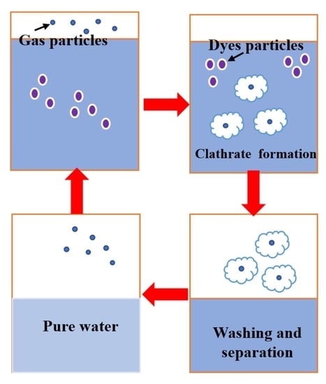
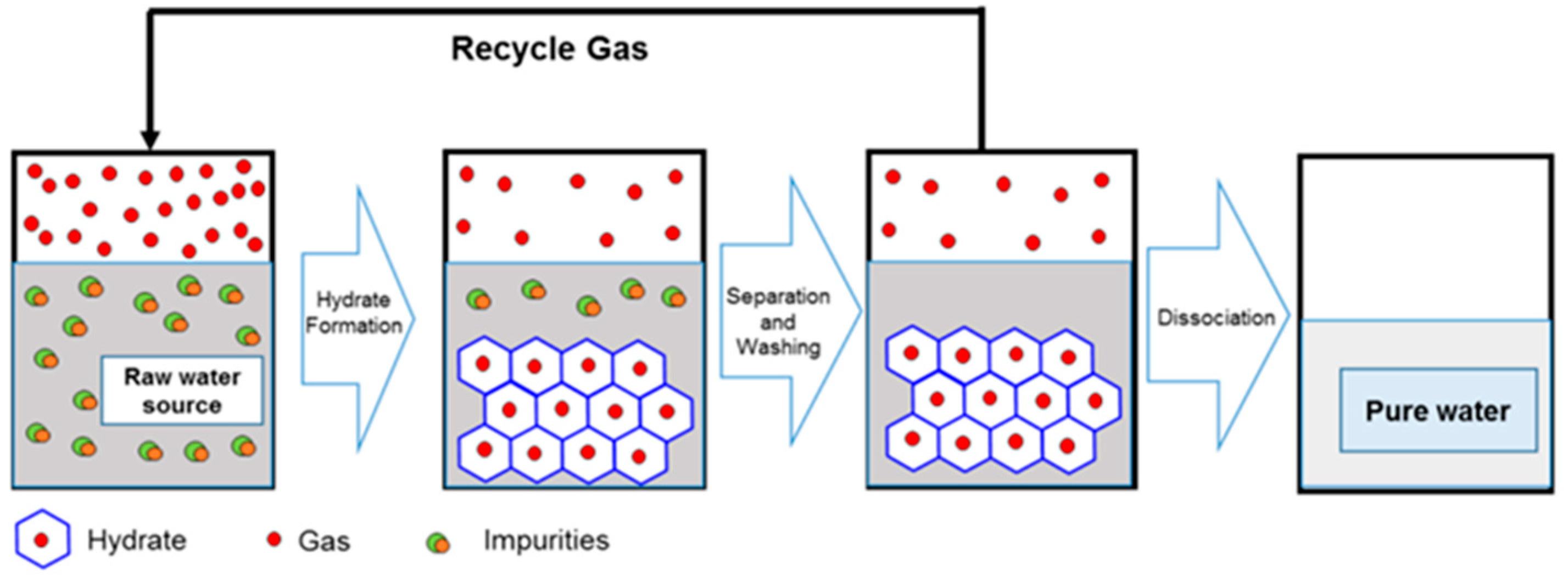
  • gas hydrates formation;
  • hydrates separation;
  • improvement of the obtained water quality, by different operation like centrifugation, washing, etc.;
  • hydrate dissociation, obtaining clean water and recovering the gas [35].
Lately, more studies have been conducted to locate the appropriate chemicals, referred to as promotors, to advocate for stable hydrate formation at a much lower pressure with a trade-off in the storage capacity regulating the dose [36]. The organics are called promotors and inhibitors of the hydrate formation because they change the environment under which hydrates develop. The most common applications for these inhibitors are flow assurance and electricity generation from natural gas hydrates. Promotors are added to hydrate-based applications so that the desired mild hydrate formation conditions may be attained. These circumstances favor stable binary hydrate production between the respective chemicals and the promotors. Most of these promotors and inhibitors are organic compounds, and the vast molecular scale of these molecules adds a layer of complexity to the models of both the hydrate and fluid phases [37].
Despite this, hydrates are used in gas separation based on the varied molecular sizes and partial pressures of the gases, which are the factors responsible for the hydrates of those gases being stable under various thermodynamic circumstances [38]. Another essential quality of hydrate is that salts are not incorporated into the structure during its creation, which makes it a candidate for use in the desalination of salt water [21,39]. Recent research has shown that the singular expansion quality of gas hydrate dissociation may be used to take advantage of a significant pressure differential with a slight temperature shift. In addition, it functions as an environmentally friendly actuator system, creating electric power from a power production system based on hydrates [40]. In order to ensure the smooth functioning of the hydrate-based processes described above, one must have a solid grasp of the characteristics of hydrates as well as the time-dependent and -independent thermodynamic behavior of hydrates.
To produce pure water from wastewater by non-traditional process, this work suggests taking advantage of the gas hydrate phenomena, where hydrate forms crystals, the crystals being formed by pure water and the gas. In the present work, Freon R134a was used as a gas in the hydrate former. Gas hydrate formed at a low temperature of about 4 °C. After forming the crystals, they were separated out of the solution and dissociated after raising the temperature, issuing pure water and R134a gas, which can be reused in the process.
So, obtaining pure water from wastewater became of great importance and attracted many research activities. The purpose of this study was to explore the efficacy of producing pure water from wastewater by using a gas hydrate, which is composed of a refrigerant gas. Furthermore, the impact of promotors on the procedure for extracting colors from the water was determined to study the phenomena of hydrate formation of refrigerant R134a for a binary system (water + R134a) and ternary system (water + R134a + promotor) for different types of promotor. In addition, the induction time of hydrate nucleation for the binary system without the promotor at different concentrations of dyes was evaluated. To our knowledge, no research has ever been completed on the effectiveness of the clathrate hydrate method for removing dyes or decreasing their concentration in water.

2. Materials and Methods

2.1. Chemicals

Refrigerant gas R-134a (CH2FCF3) with a high purity equal to 99% from a supplier (Frisco, Ostend, Belgium) was utilized with distilled water to form a hydrate. The dyes used in these experiments were potassium permanganate (KMnO4) with a purity > 99% from (BDH, Poole, UK) and povidone-iodine ((C6H9NO)n) from (Natural, Instanbul, Turkey). The promotors used in the experiments were silica gel (SiO2) with a purity > 99% from (Drytec industries, New Delhi, India), Tween 80 (C64H124O26) > 99% (Central drug house/India), and Cyclohexane (C6H12) > 99% (J. T. Baker).

2.2. Apparatus

A schematic diagram of the experimental setup used in this study is presented in Figure 4. The central part of the system is the experimental cell with a volume of 1500 cm3. The experimental cell consists of a magnetic stirrer (operated at 250 rpm), a thermocouple type k (0.1 K with a division scale), and a digital pressure gauge (5 × 10⁻⁵ bar with a division scale), used to record the temperature and pressure.
The experimental cell was connected to the system via pipes controlled with the aid of a valve for the injection of gas, a water input, and a drain valve. The experimental cell was enclosed in a plastic container as a sheath to control the temperature in the experimental cell. The cooling mixture was supplied from water bath type Julabo F10-VC, and the cooling medium used in this study was ethylene glycol/water.

2.3. Preparation of Dye Solution

The stock solution was made by dissolving 1g of each colored compound (potassium permanganate and povidone-iodine) in 1 L of distilled water to produce 1000 ppm. The preparation of a 200 mL solution with different concentrations (10, 50, and 100 ppm) of potassium permanganate and (500, 2500, 5000 ppm) povidone-iodine was carried out. From each prepared solution, an amount was taken and a diluted solution corresponding to the mentioned concentrations was made, using the dilution law. The choice of different concentrations for each dye was made according to the ability of each dye to color. The potassium permanganate and povidone-iodine concentrations were determined at a maximum wavelength of 525 nm and 310 nm, respectively, using a UV-VIS–Vis spectrophotometer (Type: U.V-1100, Shanghai, China).

2.4. Experimental Procedure

Firstly, the cell was cleaned to remove the polluted contents. The distilled water was drawn into a hosepipe after cleaning the cell. The aqueous solution entered the cell by opening the cell valve connected to the filled hosepipe. The compressor discharged the air out of the cell at a vacuum pressure of 0 bar for 15 min. The controlled jacket surrounding the cell was set to a lower temperature of 4 °C. Then, R134a gas was loaded into the cell and pressurised to the desired pressure. Initially, the system pressure was set to the expected hydrate formation temperature.
The stirrer was run at 250 rpm when the system reached stability. Then, the nucleation of hydrates was noticed visually when the temperature slowly decreased. In addition, the pressure decreased gradually with the increasing hydrate formation. Moreover, the temperature and pressure were recorded until they reached the state where there was no hydrate formation. The temperature and pressure were recorded at each 2 min interval till reaching no hydrate formation pressure. The same procedure was repeated for two dyes: potassium permanganate and povidone-iodine, with the same initial pressure to take the formation condition. Then, the same procedure was used with different promotors (cyclohexane, Tween 80, and silica gel powder) at a constant concentration of 2.5 vol%, 100 ppm, and 100 ppm, respectively, and the same initial pressure and temperature (4.5 bar and 10 °C) in order to obtain the suitable formation conditions.
When the hydrate was fully formed and grown, the drain valve was opened to discharge the remaining water (the water that had not turned into hydrate). Then, the water bath was heated to dissolve the crystal of hydrate formed. Dissolved hydrates were collected in liquid form, which were further analysed using the UV-VIS spectrophotometer in order to determine the concentration of the dye, leading to the calculation of the dye removal rate.

2.5. Dye Removal Rate

The elemental analysis for dyes in dissociated hydrate was performed using UV-VIS spectroscopy. The concentrations were used for calculating the removal efficiency for each dye as follows [41]:
Removal   Rate   ƞ % = C A 0 C A   C A 0 × 100
where CA0 and CA (in unit ppm) are the dye concentration in the feed solution and in dissociated hydrate crystals, respectively. CA was estimated by the optical UV-VIS spectrophotometer and compared to the calibration values that led to estimating the dye removal efficiency.

3. Results and Discussion

The experimental results illustrated the role of hydrate in the removal of the dyes and the water treatment and the effect of catalysts on the removal efficiency using this innovative technique.

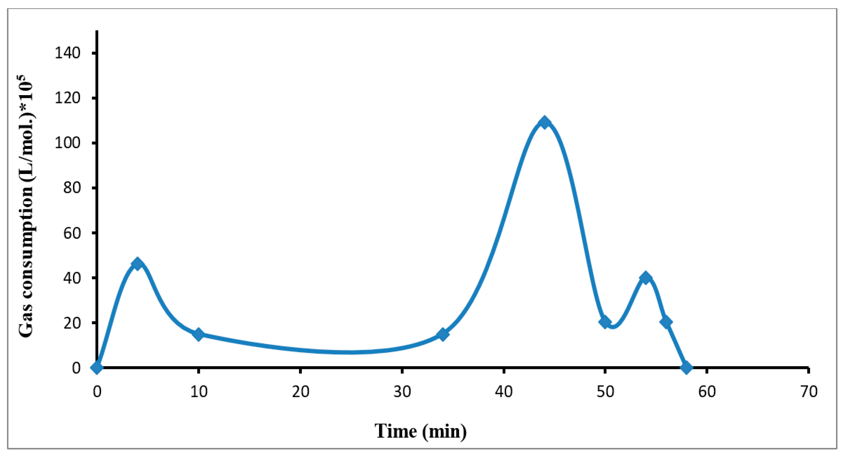
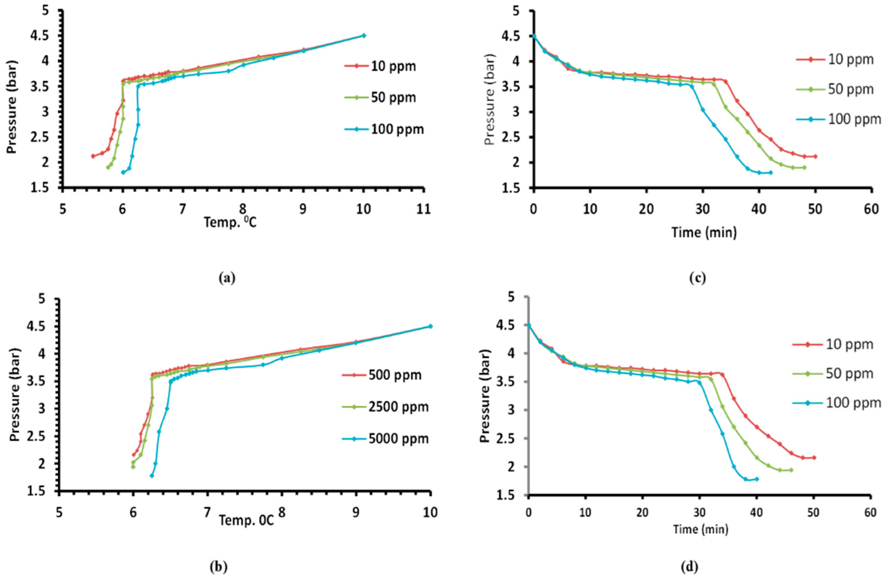
3.1. Growth Rate of R134a Hydrate Formation

The rate of hydrate was mainly expressed as the molecules of R134a that were converted to hydrate. In this work, the growth rate is described as the time for the binary and ternary systems. Figure 5 depicts the difference in the growth rate during the time for the pure water + refrigerant gas R-134a system.
The growth rate in the binary system increased first gradually during the dissolving gas stage. Then it became semi-stable during the nucleation stage, where the particles of hydrate began to grow gradually until it reached the maximum value at the formation point and the start of the hydrate growth (pressure drop), because of the increase in the driving force with pressure. This was followed by a rapid decline in the value of the growth rate of hydrate and then it returned to rising again as a result of the dissolving of a new quantity of gas to replace it, which went to the top in the form of hydrates until the value of the growth of hydrate equaled zero due to stopping the hydrate formation.

3.2. Thermodynamic Behaviour Study

The hydrate formation of R134a + solution system shows a relationship between the pressure and temperature. The temperature gradually decreased inside the cell with a gradual decrease in pressure. After that, the high-pressure drop was observed until reaching the point when the hydrate growth was completed. The decrease in the pressure was mainly owed to the hydrate formation through which rapid capture of the refrigerant gas molecules in the solid phase happened. The effect of both dyes (povidone-iodine and potassium permanganate) on the amount of hydrate formed was small. Hence, its effect was slight on the relationship between pressure and temperature, as shown in Figure 6a,b, respectively.
Generally, the effect of adding dyes on the amount of hydrate formed was small (so its effect was slight on the creation of pressure). The optimum concentrations for the user that result in a lower induction time are 100 ppm and 5000 ppm for the potassium permanganate and povidone-iodine, respectively, as shown in Table 1, because this promotor rapidly loses its effectiveness, as described by Dicharry [42,43]. Silica gel powder slightly affected the pressure of the gas hydrate formation, but on the other hand, the gas/water contact was improved and enhanced the conversion of water to hydrate, as water can be dispersed in the pores of silica gels with a very high surface area and pore volume, and then, hydrates can be formed within the pores as described by Lee and Seo [44]. Since the average pore diameter was greater than 100 nanometers (in this study, 120 nm), that led to increased hydrate formation because of increased diffusion in the larger pores, as described by Kang et al. [45].

3.3. Induction Time

The induction time is the time interval between the formation of an appreciable amount of solid phase clathrate and the initial moment of supersaturation of the solution.
The values for the induction time obtained by the relationship between the pressure and time for the pure water + refrigerant gas R-134a system are presented in Table 1.
Povidone-iodine and potassium permanganate had small effects on the induction time. As shown in Figure 6c,d, the induction time for both the povidone-iodine and potassium permanganate slightly decreased with time. The gas hydrate R-134a is an effective method for dye removal, where the hydrate consists of water and gas without impurities. The efficacy of dye removal is presented in Table 1.

3.4. Treatment Efficiency in Terms of Removal Rate

The promotors increased the removal efficiency by dissolving more gas. Thus, the hydrate increased, increasing the amount of water produced by the hydrates. Table 2 shows the treatment efficiency in terms of the removal rate with and without promotors by testing the water produced by the gas hydrate using the optical UV-VIS spectrophotometer, initially calibrated, as was mentioned in Section 2.
The obtained results for water without promotors led to a removal rate of 89% for the potassium permanganate and 90% for povidone-iodine, respectively. Using the silica gel powder as a promotor determined the highest efficiency of removal, taking into consideration the sorption properties of silica gel, which is well-known as a suitable adsorbent with high porosity [46,47]. The silica gel results were related to the removal rate of 92% for the potassium permanganate and 95% for povidone-iodine, respectively. The cyclohexane achieved results that were comparable to the results achieved for the silica gel (90% for potassium permanganate and 94% for povidone-iodine), but it could be considered the best for the easy separation from dissolved hydrates depending on its density (insoluble in water) as well as easy cleaning of the cell after use. This cannot be achieved with the Tween 80 because of its dissolution in water, and the results achieved were 86% for the potassium permanganate and 91% for povidone-iodine.

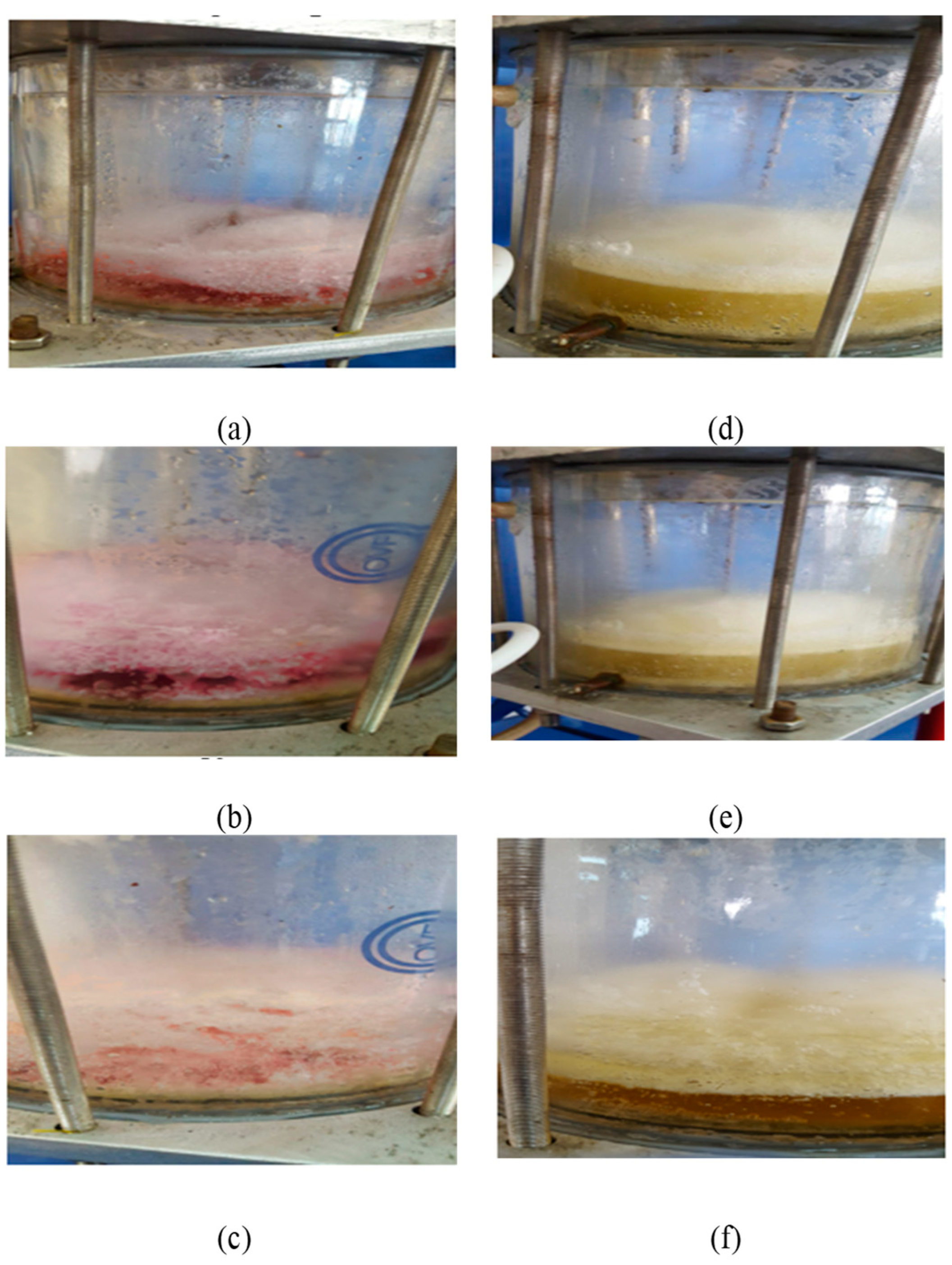
3.5. Gas Hydrate Formation

The pictures showing the formation of hydrate via the cell side are presented in Figure 7.
The experiments were carried out according to the isochoric conditions. After adding water, the gas was injected (until it reached the required pressure while ensuring the initial temperature stability). In the dissolution stage, the temperature decreased slowly and was accompanied by the gas dissolving in water until reaching a low dissolving stage. The pressure stabilized in the nucleation stage.
The gas hydrate R-134a is an effective treatment method for water contaminated with colored compounds, as shown in Figure 8.

4. Conclusions

Water is essential for mankind, and nowadays the global warming effect will makes it even scarce. Industrial water usage has been growing and water shortages require its recycling in industries. Wastewater pollution by dyes represents a high percentage of industrial water fouling. The current work had the main goal of demonstrating the effectiveness of the clathrate hydrate method for removing dyes or decreasing their concentration in water, and focused on the effectiveness of the gas hydrate phenomena applied for dye removal from water, pointing out the role of hydrate in the water treatment as well as the catalytic effects on the treatment efficiency. The clathrate hydrates represent a distinctive, unusual, scientifically significant, and practically important class of solid-state materials. More studies realised that they are simultaneously a tremendous energy source and, in the face of global warming, a potent greenhouse gas release disaster of unprecedented magnitude just waiting to happen. In the presented case study, the R134a refrigerant gas was successfully used to form hydrate with synthetic wastewater, containing two types of colored compounds (potassium permanganate and povidone-iodine).
This technique is effective for removing dyes or reducing their concentration in water, by forming easy dissociable hydrates. Pure water and the hydrate gas form a compact layer at the top of the solution, leaving at the bottom a layer containing a highly dye-concentrated solution. The obtained removal rate ranged between 86–92% for povidone-iodine and 90–95% for potassium permanganate. The removal efficiency increased with dye concentration in the solution, which showed an increase in the clear water amount produced by the hydrates. The effect of dyes on the hydrate formation conditions (decreasing the induction time, temperature, and pressure) had a slight influence. The removal efficiency increased by adding the promotors, which depended on dissolving a larger amount of gas. Thus, the hydrate increased, thus increasing the water amount produced by the hydrates. The use of the gas hydrate technology for dye removal from wastewater has a high potential for practical applications, i.e., the dye removal in the desalination process (the removal of the salts), where the hydrate consists of water and gas without impurities.

Author Contributions

Conceptualization, M.S.M., S.T.A.-H., R.S.A.-M., S.M.A., A.A. and I.C.; methodology, M.S.M., S.T.A.-H., R.S.A.-M., S.M.A., A.D.S. and I.C.; software, M.S.M., A.A., A.D.S., B.S. and I.C.; validation, B.S. and I.C.; formal analysis, M.S.M., B.S. and I.C.; investigation, M.S.M., S.T.A.-H., R.S.A.-M., S.M.A., A.A. and I.C.; resources, B.S., F.Y.A. and I.C.; data curation, I.C.; writing—original draft preparation, M.S.M., S.T.A.-H., R.S.A.-M., S.M.A., A.A., M.J. and A.D.S.; writing—review and editing, B.S. and I.C.; visualization, B.S. and I.C.; supervision, I.C.; project administration, I.C. All authors have read and agreed to the published version of the manuscript.

Funding

This research received no external funding.

Institutional Review Board Statement

Not applicable.

Informed Consent Statement

Not applicable.

Data Availability Statement

Not applicable.

Acknowledgments

The authors would like to thank the University of Technology, Baghdad, Iraq and the “Gheorghe Asachi” Technical University of Iasi for the generous support of this research. The authors thankfully acknowledge the scientific support of the Department of Chemical Engineering and the Nanotechnology and Advanced Material Research Center, University of Technology-Iraq, Baghdad, Iraq.

Conflicts of Interest

The authors declare no conflict of interest.

References

  1. Singha, K.; Pandit, P.; Maity, S.; Sharma, S.R. Harmful Environmental Effects for Textile Chemical Dyeing Practice. In Green Chemistry for Sustainable Textiles; Ibrahim, N., Hussain, C.M., Eds.; Woodhead Publishing: Cambridge, UK, 2021; pp. 153–164. [Google Scholar]
  2. Bayomie, O.S.; Kandeel, H.; Shoeib, T.; Yang, H.; Youssef, N.; El-Sayed, M.M.H. Novel approach for effective removal of methylene blue dye from water using fava bean peel waste. Sci. Rep. 2020, 10, 7824. [Google Scholar] [CrossRef]
  3. Saja, S.; Bouazizi, A.; Achiou, B.; Ouaddari, H.; Karim, A.; Ouammou, M.; Aaddane, A.; Bennazha, J.; Younssi, S.A. Fabrication of low-cost ceramic ultrafiltration membrane made from bentonite clay and its application for soluble dyes removal. J. Eur. Ceram. Soc. 2020, 40, 2453–2462. [Google Scholar] [CrossRef]
  4. Kim, S.; Chen, J.; Cheng, T.; Gindulyte, A.; He, J.; He, S.; Li, Q.; Shoemaker, B.A.; Thiessen, P.A.; Yu, B.; et al. PubChem in 2021: New data content and improved web interfaces. Nucleic Acids Res. 2021, 49, D1388–D1395. [Google Scholar] [CrossRef] [PubMed]
  5. Trott, A.T. Emergency Wound Care: An Overview. In Wounds and Lacerations, 4th ed.; Trott, A.T., Ed.; W.B. Saunders: Philadelphia, PA, USA, 2012; pp. 1–3. [Google Scholar]
  6. Alardhi, S.M.; Abdalsalam, A.H.; Ati, A.A.; Abdulkareem, M.H.; Ramadhan, A.A.; Taki, M.M.; Abbas, Z.Y. Fabrication of polyaniline/zinc oxide nanocomposites: Synthesis, characterization and adsorption of methylene orange. Polym. Bull. 2023, 80, 1–27. [Google Scholar] [CrossRef]
  7. Alardhi, S.M.; Fiyadh, S.S.; Salman, A.D.; Adelikhah, M. Prediction of methyl orange dye (MO) adsorption using activated carbon with an artificial neural network optimization modeling. Heliyon 2023, 9, e12888. [Google Scholar] [CrossRef]
  8. Jamee, R.; Siddique, R. Biodegradation of synthetic dyes of textile effluent by microorganisms: An environmentally and economically sustainable approach. Eur. J. Microbiol. Immunol. 2019, 9, 114–118. [Google Scholar] [CrossRef]
  9. Gadekar, M.R.; Ahammed, M.M. Coagulation/flocculation process for dye removal using water treatment residuals: Modelling through artificial neural networks. Desalination Water Treat. 2016, 57, 26392–26400. [Google Scholar] [CrossRef]
  10. Sala, M.; Gutiérrez-Bouzán, M.C. Electrochemical Techniques in Textile Processes and Wastewater Treatment. Int. J. Photoenergy 2012, 2012, 629103. [Google Scholar] [CrossRef] [Green Version]
  11. Al-Jadir, T.; Alardhi, S.M.; Alheety, M.A.; Najim, A.A.; Salih, I.K.; Al-Furaiji, M.; Alsalhy, Q.F. Fabrication and Characterization of Polyphenylsulfone/Titanium Oxide Nanocomposite Membranes for Oily Wastewater Treatment. J. Ecol. Eng. 2022, 23, 1–13. [Google Scholar] [CrossRef]
  12. Alardhi, S.M.; Alrubaye, J.M.; Albayati, T.M. Hollow Fiber Ultrafiltration Membrane for Methyl Green Dye Removal. Eng. Technol. J. 2020, 38, 1077–1083. [Google Scholar] [CrossRef]
  13. Alardhi, S.M.; Alrubaye, J.M.; Albayati, T.M. Removal of Methyl Green Dye from simulated waste water using Hollow Fiber Ultrafiltration Membrane. IOP Conf. Ser. Mater. Sci. Eng. 2020, 928, 052020. [Google Scholar] [CrossRef]
  14. Elumalai, S.; Muthuraman, G. Removal and Recovery of Methyl Violet Dye from Industrial Wastewater by Liquid–Liquid Extraction; Springer: Singapore, 2018. [Google Scholar]
  15. Wijannarong, S.; Aroonsrimorakot, S.; Thavipoke, P.; Kumsopa, C.; Sangjan, S. Removal of Reactive Dyes from Textile Dyeing Industrial Effluent by Ozonation Process. APCBEE Procedia 2013, 5, 279–282. [Google Scholar] [CrossRef] [Green Version]
  16. Ajmal, A.; Majeed, I.; Malik, R.N.; Idriss, H.; Nadeem, M.A. Principles and mechanisms of photocatalytic dye degradation on TiO2based photocatalysts: A comparative overview. RSC Adv. 2014, 4, 37003–37026. [Google Scholar] [CrossRef]
  17. Fu, J.; Kyzas, G.Z. Wet air oxidation for the decolorization of dye wastewater: An overview of the last two decades. Chin. J. Catal. 2014, 35, 1–7. [Google Scholar] [CrossRef]
  18. Ganaie, R.J.; Rafiq, S.; Sharma, A. Recent Advances in Physico-chemical Methods for Removal of Dye from Wastewater. IOP Conf. Ser. Earth Environ. Sci. 2023, 1110, 012040. [Google Scholar] [CrossRef]
  19. Salman, S.; Sheikh, C.; Hasan, M.; Hasan, N.; Kubra, K.T.; Rehan, A.I.; Awual, E.; Rasee, A.I.; Waliullah, R.; Hossain, M.S.; et al. Chitosan-coated cotton fiber composite for efficient toxic dye encapsulation from aqueous media. Appl. Surf. Sci. 2023, 622, 157008. [Google Scholar] [CrossRef]
  20. Hassanpouryouzband, A.; Joonaki, E.; Farahani, M.V.; Takeya, S.; Ruppel, C.; Yang, J.; English, N.J.; Schicks, J.M.; Edlmann, K.; Mehrabian, H.; et al. Gas hydrates in sustainable chemistry. Chem. Soc. Rev. 2020, 49, 5225–5309. [Google Scholar] [CrossRef]
  21. Al-Hemeri, S.T.; Al-Mukhtar, R.S.; Mahmood, L.W. Thermodynamic and Kinetic Investigation of Desalination by Refrigerant Clathrate Hydrate Formation. Eng. Technol. J. 2019, 37, 29–44. [Google Scholar] [CrossRef]
  22. Marboeuf, U.; Schmitt, B.; Petit, J.-M.; Mousis, O.; Fray, N. A cometary nucleus model taking into account all phase changes of water ice: Amorphous, crystalline, and clathrate. Astron. Astrophys. 2012, 542, A82. [Google Scholar] [CrossRef]
  23. Lee, J.; Kenney, J.W. Clathrate Hydrates. In Solidification; IntechOpen: London, UK, 2018. [Google Scholar]
  24. Chen, G.-J.; Guo, T.-M. A new approach to gas hydrate modelling. Chem. Eng. J. 1998, 71, 145–151. [Google Scholar] [CrossRef]
  25. Ahmadi, M.A.; Bahadori, A. Gas Hydrates. In Fluid Phase Behavior for Conventional and Unconventional Oil and Gas Reservoirs; Gulf Professional Publishing: Boston, MA, USA, 2017; pp. 405–444. [Google Scholar]
  26. AL-Mukhtar, R.S.; Remedhan, S.T.; Hussin, M.N. Study of The Influence of Different Variables on Clathrate Practical Applications in Phenol Removal. Eng. Technol. J. 2020, 38, 1373–1383. [Google Scholar] [CrossRef]
  27. Thakre, N.; Jana, A.K. Physical and molecular insights to Clathrate hydrate thermodynamics. Renew. Sustain. Energy Rev. 2020, 135, 110150. [Google Scholar] [CrossRef]
  28. Dong, H.; Zhang, L.; Wang, J. Formation, Exploration, and Development of Natural Gas Hydrates. Energies 2022, 15, 5951. [Google Scholar] [CrossRef]
  29. Yu, C.; Fan, S.; Lang, X.; Wang, Y.; Li, G.; Wang, S. Hydrogen and chemical energy storage in gas hydrate at mild conditions. Int. J. Hydrogen Energy 2020, 45, 14915–14921. [Google Scholar] [CrossRef]
  30. Marwa, N. Experimental Investigation to Study Clathrate Based for Removal Heavy Metals and Phenol from Wastewater. Master’s Thesis, Chemical Engineering Department—University of Technology, Baghdad, Iraq, 2019. [Google Scholar]
  31. Hegde, G.A.; Sum, A.K.; Danielson, T.J. Multiphase flow modeling for gas hydrates in flow assurance. In Proceedings of the Offshore Technology Conference, Houston, TX, USA, 4–7 May 2015. [Google Scholar]
  32. Max, M. Natural Gas Hydrate in Oceanic and Permafrost Environments; Springer: Berlin/Heidelberg, Germany, 2003. [Google Scholar]
  33. Hai, S. Water Purifying by Gas Hydrate: Potential Applications to Desalination and Wastewater Treatments. Chem. Eng. Trans. 2020, 78, 67–72. [Google Scholar]
  34. Babu, P.; Nambiar, A.; He, T.; Karimi, I.A.; Lee, J.D.; Englezos, P.; Linga, P. A review of clathrate hydrate-based desalination to strengthen energy–water nexus. ACS Sustain. Chem. Eng. 2018, 6, 8093–8107. [Google Scholar] [CrossRef]
  35. Seo, S.D.; Hong, S.Y.; Sum, A.K.; Lee, K.H.; Lee, J.D.; Lee, B.R. Thermodynamic and kinetic analysis of gas hydratesfor desalination of saturated salinity water. Chem. Eng. J. 2019, 370, 980–987. [Google Scholar] [CrossRef]
  36. Gupta, A.; Baron, G.V.; Perreault, P.; Lenaerts, S.; Ciocarlan, R.-G.; Cool, P.; Mileo, P.G.; Rogge, S.; Van Speybroeck, V.; Watson, G.; et al. Hydrogen Clathrates: Next Generation Hydrogen Storage Materials. Energy Storage Mater. 2021, 41, 69–107. [Google Scholar] [CrossRef]
  37. Hussain, H.H.; Husin, H. Review on Application of Quaternary Ammonium Salts for Gas Hydrate Inhibition. Appl. Sci. 2020, 10, 1011. [Google Scholar] [CrossRef] [Green Version]
  38. Kim, E.; Ko, G.; Seo, Y. Greenhouse Gas (CHF3) Separation by Gas Hydrate Formation. ACS Sustain. Chem. Eng. 2017, 5, 5485–5492. [Google Scholar] [CrossRef]
  39. Xu, H.; Khan, M.N.; Peters, C.J.; Sloan, E.D.; Koh, C.A. Hydrate-Based Desalination Using Cyclopentane Hydrates at Atmospheric Pressure. J. Chem. Eng. Data 2018, 63, 1081–1087. [Google Scholar] [CrossRef]
  40. Obara, S.; Mikawa, D. Electric power control of a power generator using dissociation expansion of a gas hydrate. Appl. Energy 2018, 222, 704–716. [Google Scholar] [CrossRef]
  41. Cha, J.-H.; Seol, Y. Increasing Gas Hydrate Formation Temperature for Desalination of High Salinity Produced Water with Secondary Guests. ACS Sustain. Chem. Eng. 2013, 1, 1218–1224. [Google Scholar] [CrossRef]
  42. Dicharry, C.; Duchateau, C.; Asbaï, H.; Broseta, D.; Torré, J.P. Carbon dioxide gas hydrate crystallisation in porous silica gel particles partially saturated with a surfactant solution. Chem. Eng. Sci. 2013, 98, 88–97. [Google Scholar] [CrossRef] [Green Version]
  43. Al Hemeri, S.T.; Al Mukhtar, R.S.; Mohammed, M.S. Study the effect of organic promoters on thermodynamics behaviour for refrigerant gas clathrate hydrate. IOP Conf. Ser. Mater. Sci. Eng. 2019, 579, 012021. [Google Scholar] [CrossRef]
  44. Lee, S.; Seo, Y. Experimental Measurement and Thermodynamic Modeling of the Mixed CH4 + C3H8 Clathrate Hydrate Equilibria in Silica Gel Pores: Effects of Pore Size and Salinity. Langmuir 2010, 26, 9742–9748. [Google Scholar] [CrossRef]
  45. Kang, S.-P.; Lee, J.-W.; Ryu, H.-J. Phase behaviour of methane and carbon dioxide hydrates in meso-and macro-sized porous media. Fluid Phase Equilibria 2008, 274, 68–72. [Google Scholar] [CrossRef]
  46. Mondal, S. Methods of Dye Removal from Dye House Effluent—An Overview. Environ. Eng. Sci. 2008, 25, 383–396. [Google Scholar] [CrossRef]
  47. Salman, S.; Hasan, N.; Hasan, M.; Kubra, K.T.; Sheikh, C.; Rehan, A.I.; Waliullah, R.; Rasee, A.I.; Awual, E.; Hossain, M.S.; et al. Improving copper(II) ion detection and adsorption from wastewater by the ligand-functionalized composite adsorbent. J. Mol. Struct. 2023, 1282, 135259. [Google Scholar] [CrossRef]
Figure 1. Simple clathrate hydrate structure, adapted from [30].
Water 15 02227 g001
Figure 2. Mechanisms of wastewater treatment by clathrate, adapted from [32].
Water 15 02227 g002
Figure 3. A concept for water treatment via gas hydrate process, adapted from the open source [33].
Water 15 02227 g003
Figure 4. The schematic diagram of the experimental setup for treatment of contaminated water with potassium permanganate and povidone-iodine using clathrate hydrate technique: (1) gas cylinder; (2) needle valve; (3) gas compressor; (4) condenser; (5) accumulator of gas; (6) experimental cell; (7) magnetic stirrer; (8) water pump; (9) digital pressure gauges; (10) temperature sensor; (11) valve drain; (12) chiller; (13) interface system; (14) computer.
Water 15 02227 g004
Figure 5. The R134a hydrate growth rate against time in the pure water + refrigerant gas R-134a system.
Water 15 02227 g005
Figure 6. The various effect during the formation of R-134a hydrate for (a) potassium permanganate and (b) povidone-iodine in studying the effect of different concentrations on temperature and pressure, and (c) potassium permanganate and (d) povidone-iodine in studying the effect of pressure and time.
Water 15 02227 g006
Figure 7. Typical sequence for R134a clathrate hydrate formation via (a) dissolution and the start of nucleation, (b) turbidity point and the beginning of the formation of growth, and (c) termination of growth.
Water 15 02227 g007
Figure 8. Photos showing images through the formation stage with potassium permanganate at (a) 10 ppm, (b) 50 ppm, (c) 100 ppm, and povidone-iodine at (d), 500 ppm, (e) 2500 ppm, and (f) 1000 ppm.
Water 15 02227 g008
Table 1. Induction time (min) and dye removal efficacy for potassium permanganate and povidone-iodine.
DyesConcentration
(ppm)
Induction Time
(min)
Dye Removal Efficacy
(%)
Potassium permanganate103586
503288.5
1002992
Povidone-iodine5003490
25003192
50003095
Table 2. Dye removal efficiency with and without promoters.
PromotorsDye Removal Rate %
Potassium Permanganate (ppm)Povidone-Iodine (ppm)
105010050025005000
Without8690
Tween 80878889909191
Cyclohexane888990919394
Silica gel899192929495
Disclaimer/Publisher’s Note: The statements, opinions and data contained in all publications are solely those of the individual author(s) and contributor(s) and not of MDPI and/or the editor(s). MDPI and/or the editor(s) disclaim responsibility for any injury to people or property resulting from any ideas, methods, instructions or products referred to in the content.

