Review

Process Water Management and Seepage Control in Tailings Storage Facilities: Engineered Environmental Solutions Applied in Chile and Peru

1
Civil Works and Geology Department, Catholic University of Temuco, Temuco 4780000, Chile
2
Geológica Consultores, Lima 15001, Peru
3
School of Civil Engineering, Pontificia Universidad Católica de Valparaíso, Valparaíso 2340000, Chile
4
Department of Management, Economics, and Industrial Engineering, Politecnico di Milano, 20156 Milan, Italy
*
Author to whom correspondence should be addressed.
Water 2023, 15(1), 196; https://doi.org/10.3390/w15010196
Submission received: 28 November 2022 / Revised: 23 December 2022 / Accepted: 26 December 2022 / Published: 3 January 2023

Abstract

:
In the past thirty years many mining projects in Chile and Peru have used: (i) polymeric geomembranes and (ii) design-and-build cutoff trenches, plastic concrete slurry walls, and grout curtain systems to control seepage at tailings storage facilities (TSFs). Geosynthetics are a viable alternative at a TSF dam for clay cores or impermeable materials, mainly because of their marked advantages in cost, installation, and construction time. This article describes the use of geosynthetics liners and cutoff trench–plastic concrete slurry walls–grout curtain systems in TSF dams in Chile and Peru mining, with the objective to decrease seepage to the environment, considering different dam material cases such as: cycloned tailings sand dams, borrow dams, and mine waste rock dams. Finally, this article discusses aspects of geosynthetic technology acceptance in the local regulatory frameworks, lessons learned, and advances. It focuses on the use and implementation of geosynthetics in TSFs in Chile and Peru, which have some of the highest TSF dams in the world, as well as a wet environment, dry environment, extreme topography, and severe seismic conditions. These conditions constitute a challenge for manufacturers, engineers, and contractors, who must achieve optimal technical solutions, while being environmentally aware and economic.

1. Introduction

1.1. Environmental Issues Related to Tailings Storage Facilities

Historically Chile and Peru have been known as mining countries. Some of the biggest copper mining operations in the world take place in these countries, in some cases achieving 150,000 metric tons per day (mtpd) of sulfide copper ore production. These nations have focused their economies on mining over recent decades. These copper mines, which use concentration metallurgical processes, produce a total of approximately 145,500 mtpd of mine tailings that must to be stored in a responsible and sustainable manner [1].
Considering the selective properties of the physical–chemical metallurgical process, the unprofitable fraction, which represents for copper minerals about 97% of the ore processed, is classified as waste and is called mine tailings or gangue [2]. In general, copper gangue is the mine waste that remains after the copper concentrate is extracted from the ore. Copper mine tailings are described as like a slurry of ground rock (containing different metals, e.g., Co, Cd, Al, Cr, As, Mn, Pb, Fe, Zn, Hg, Ni, Va, Cu, and Mo, among others), process water (containing different nonmetal elements, e.g., sulfates, nitrates, chloride, ammonia, among others), and chemical reagents (e.g., copper sulfate, sodium cyanide, sodium ethyl xanthate, pine oil tar, fatty acid soaps, collectors, dithiophosphates, foaming agents, flocculants, and lime, among others) that remain after flotation processing. The chemical structure of mine tailings is complex and diverse, and varies according to the mineralogy and how the ore is treated. These mine wastes are generally made up of slurry; they are conveyed in pipelines or flumes to a TSF. In the past, in some cases mine tailings have been discharged into lakes, rivers, and the sea; nowadays, this is banned, and currently mine tailings are managed on land in different topographical areas [2].
Therefore, from an environmental perspective, most mine tailings cannot be classified as inert material, and must be managed in a responsible manner with due care for nature [2,3,4]. Mining wastes, specifically mine tailings, must be isolated from interaction with water, soil, and air. Even in circumstances where mine tailings material is geochemically inert, the quantity of tailings may overload the capacity of the environment [5,6].
This means TSFs, which in some cases store hundred million of tons of mine tailings and have a 200 m dam height, must be designed and built for:
  • Safe storage of mine tailings, process water, and rainfall water;
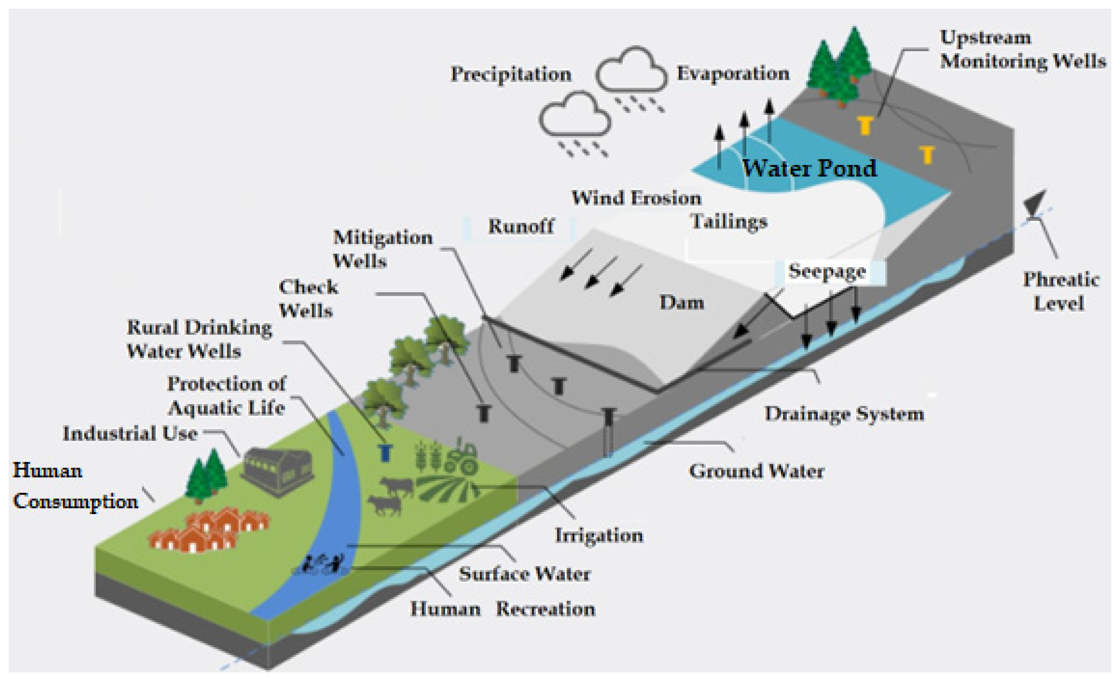
  • Mitigating leakage from the TSF through the dam and adjacent zones, for environmental care of soils, and ground water;
  • Controlling internal dam erosion (piping issues);
  • Providing filter and drainage capacity of the dam;
  • Improving the long-term physical and geochemical stability of the TSF (operation closure and post closure), considering severe seismic activity and potential extreme floods.
Over the past decades many TSFs in Chile and Peru have considered the use of the following materials to build dams: cycloned tailings sand (hydrocyclone underflow), and borrow or mine waste rock materials. Some factors that need to be analyzed to select an optimal dam material are: impoundment/dam ratio, construction materials availability, geochemical characteristics, seismic conditions, and the topographic/climate characteristics for construction schedule issues.
Several social and environmental issues associated with mine tailings governance in Chile and Peru are linked to the potential pollution of the environment (soil, ground water, surface water, and air) [2,5]. A key environmental feature to take into account is to depress dust emission carried by winds from TSFs to communities. Particulate matter emission mitigation will play a key role in respect to regulatory air quality admissible limits. Some mine tailings particulate matter control solutions to apply are: cover (soil or borrow material), phytostabilization, top soil, and chemical agglomeration [7].
In the past decades, there were relevant advances in mine tailings dewatering technologies (best available technologies considering high solid content by weight (Cw) in tailings), TSF infiltration mitigation, and mine tailings control worldwide. However, mine tailings spill accidents still happen, such as the events at Mount Polley (Canada, 2014), Fundao Samarco (Brazil, 2015), Corrego do Feijao Brumandinho (Brazil, 2019), Jagersfontain (South Africa, 2022), and Williamson (Tanzania, 2022), mainly due to: (i) natural causes (floods, earthquakes, debris flows, etc.) and (ii) human origin causes (dam failure, inadequate tailings/water management, inadequate construction, etc.) [2]. These events confirm that for mine tailings, there is not yet a level of safety for neighboring communities that would guarantee their physical stability and protect ecosystem. As a consequence, tailings transport and storage activities require careful control and responsible social and environmental governance [8].
Likewise, mine tailings frequently face social and environmental controversy, considering the proximity of the TSF to villages, towns, and cities, the potential environmental effects on the surrounding soil and water, the use of land with heritage and cultural significance, and dust emissions, among others [9].
For its part, seepage from process water (contacted water with mine tailings) of TSF also signifies an important issue that the mining industry must address, due to its potential negative impacts on the health of the population, nature, and other economic activities’ development, such as that of cities, forestry, agriculture, fishing and livestock [3] (see Figure 1).
Nowadays, socioenvironmental conflicts affect 50% of the current mine tailings production in Chile and Peru, and future forecast indicate that due to the increase in the generation of commodities such as Au, Ag, Cu, and Mo, the quantities of mine tailings will increase, generating the expansion of the current TSFs and the implementation of new sites [3].
Today, unprecedented levels of mine tailings production are being reached in Chile and Peru, in the order of 800 million metric tons and 400 million of metric tons of mine tailings per year, respectively [3]. They are stored in valleys with steep topographies located in the Andes mountain range, where the heights of the tailings storage dams exceed 100 m and even in some cases 200 m and 300 m (see Table 1).
All the aspects mentioned above show that, today, the governance of TSFs is a concern of great relevance for society. Mines must face not only the challenges of technical and economic aspects associated with designing, constructing, operating, closing, and post-closing of their TSFs, but also those manifested from the ecological nature, making necessary the establishment and development of a holistic mine tailings management system that considers all the issues necessary to ensure the adequate performance of these TSFs, minimizing their risk of instability and favoring safe operation in accordance with the sustainable development of our society [9,10].
A discussion of design, construction, and operation applications with geosynthetics elements at TSFs located in Chile and Peru will be presented in the following sections.

1.2. Aim of the Article

This article describes the use of geosynthetics liners and cutoff trench–plastic concrete slurry wall–grout curtain systems in TSF dams in Chile and Peru, considering different dam materials such as: cycloned tailings sand dams, borrow dams, and mine waste rock dams, with the objective to decrease seepage to environment.
In addition, the following key technical and design aspects are discussed in this article: (i) types of geosynthetic materials (PVC), (HDPE), (LLDPE), (ii) thickness and performance of geosynthetics, (iii) types of cushion layers for geosynthetic materials, (iv) constructability, (v) QA/QC, and (vi) sustainability.
Finally, this article discusses aspects of geosynthetic technology acceptance in the local regulatory frameworks, lessons learned, and advances. It focuses on the use and implementation of geosynthetics in TSFs in Chile and Peru, which have some of the highest TSF dams in the world, as well as a wet environment, dry environment, complex topographical characteristics, and extreme seismic conditions. These conditions constitute a challenge for manufacturers, engineers, and contractors, who must achieve optimal technical solutions, while being environmentally aware and economic.

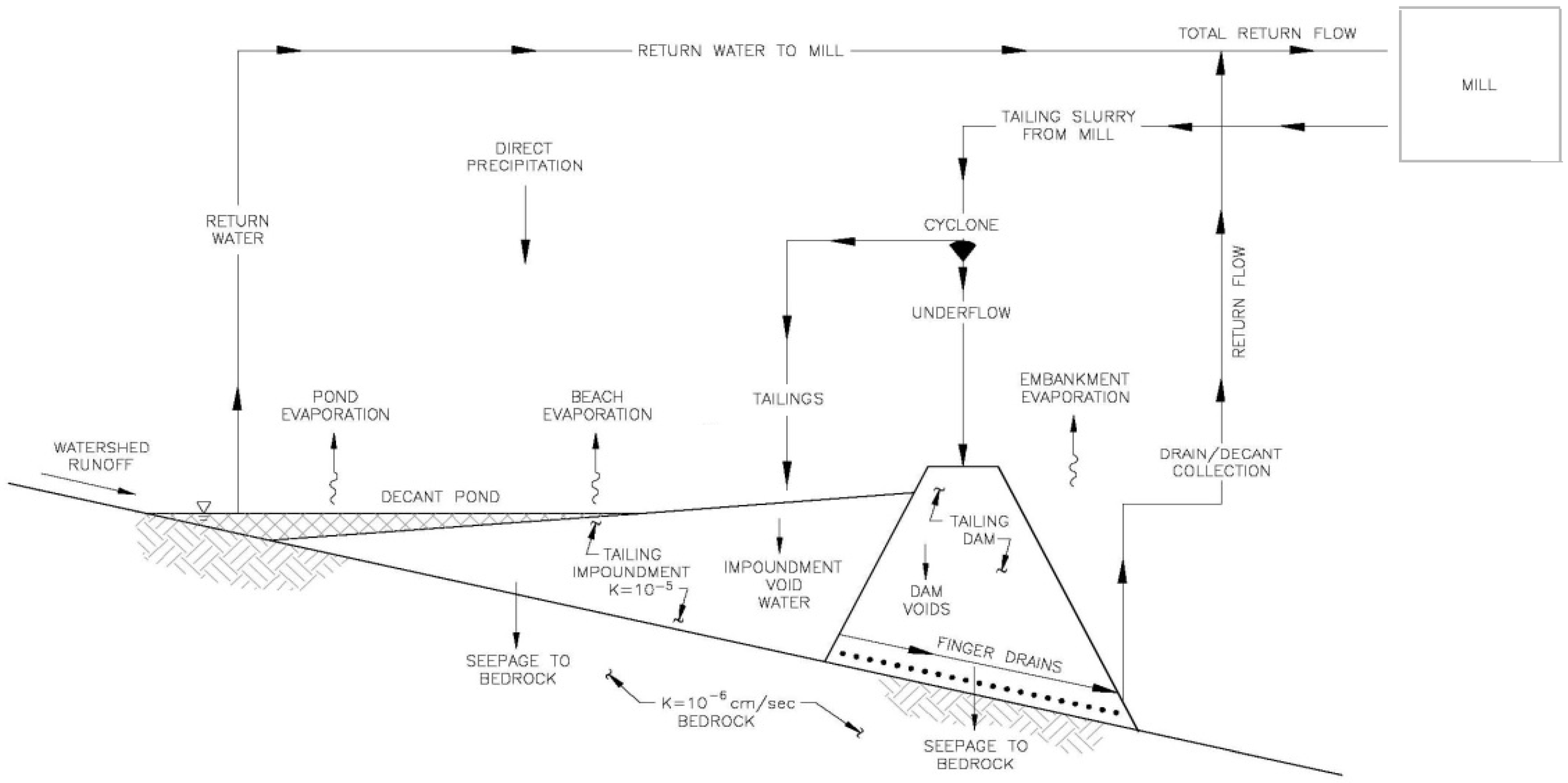
2. Process Water Management and Seepage Control in Tailings Storage Facilities

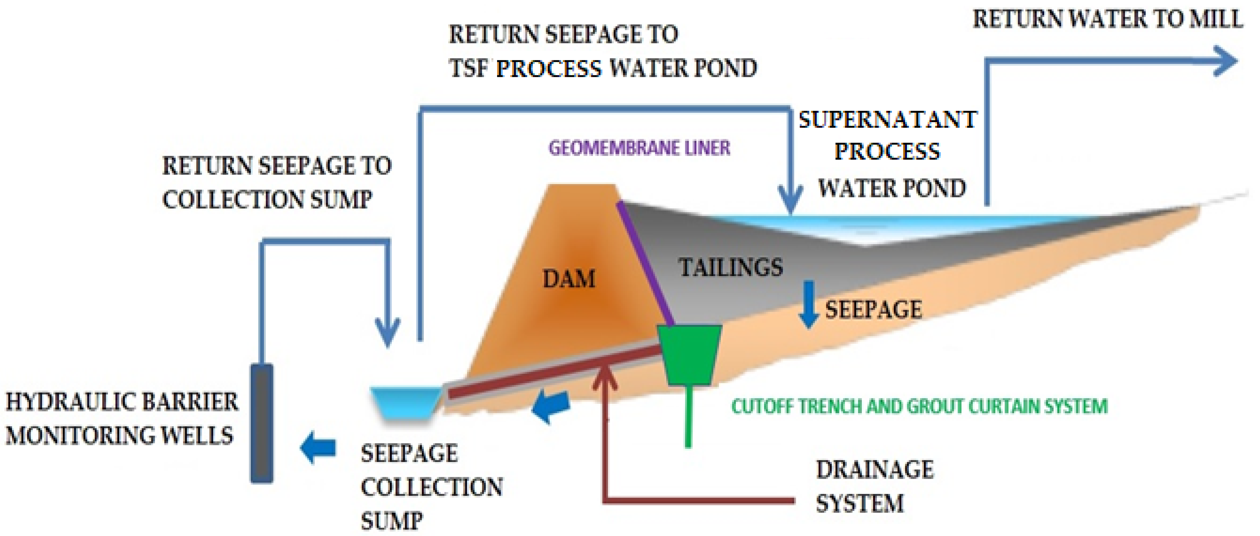
2.1. Seepages in Tailings Storage Facilities

Seepage is the movement of process water (water that has had contact with mine tailings) through and around the TSF embankment. The main characteristics altering the flux of seepage in a dam are infiltration mobility of the unsaturated zone with mine tailings and depth to the ground water table [11,12].
The preferred method to control flux of seepage through TSF dams has been to increase stability of the embankment, decreasing the phreatic line. Evaluation of the flux and pathway of seepage is conducted using hydraulics. The same parameters that are considered during the engineering study stage to forecast the phreatic line can be considered to estimate the flux of seepage during the TSF operation phase. Similarly, parameters, such as permeability of the TSF dam and rock–soil foundation system, that might influence the phreatic line, also change seepage fluxes [11,12] (see Figure 2).
Seepage study can require data from geologic, geotechnic, geomechanics, hydrologic, and hydrogeologic evaluations, and characterizations of fluxes such as: (i) runoff, (ii) infiltration–percolation, and (iii) consolidation of mine tailings [11,12].
Geological factors influencing seepage are the occurrence of damaged rock, karstic rocks, fine soil lenses, and geologic failures with large differences in hydraulic conductivity characteristics. Hydrological information is influenced by rainfall pattern, topsoil presence, vegetation, surface conditions, and provides data to estimate infiltration fluxes [11,12].
Hydrogeological analysis can resolve: (i) the degree of anisotropy and critical path of the seepage, (ii) the rock and soil conditions for ground water fluxes studies, (iii) the consolidation degree of the mine tailings and foundation soil, (iv) the capillary stratum and the size of the unsaturated zone, and (v) hydraulic conductivity, transmissivity, and the storage capacity of the mine tailings and underlying aquifer [11,12].

2.2. Seepage Control

There are two alternatives for managing contact process water in TSFs: keeping it in the TSF or capturing it after it exits the TSF. Infiltration actions are studied in the engineering stages of TSFs [13,14,15]. The main goals are to maintain secure the TSF dam stability, decrease leakages, and protect the chemical characteristics of the water in the environment. Alternatives for seepage mitigation include: (i) installation of geosynthetic liners beneath the entire impoundment zone of the TSF, (ii) building a drainage system for seepage collection, (iii) constructing a seepage collection sump, (iv) pumping systems (recycled process water), (v) seepage treatment systems, sometimes in conjunction with hydraulic barriers, (vi) installation of low-permeability barriers (e.g., cutoff trenches, plastic concrete slurry walls, grout curtains), (vii) thickening and filtering of tailings prior to disposal (thickened, paste or filtered tailings), and (viii) decreasing the hydraulic head in the embankment by locating the supernatant process water pond away from the TSF dam. Some of these alternatives are described in the follow paragraphs below [1,3,7,11,12,16].

2.2.1. Geomembrane Liners

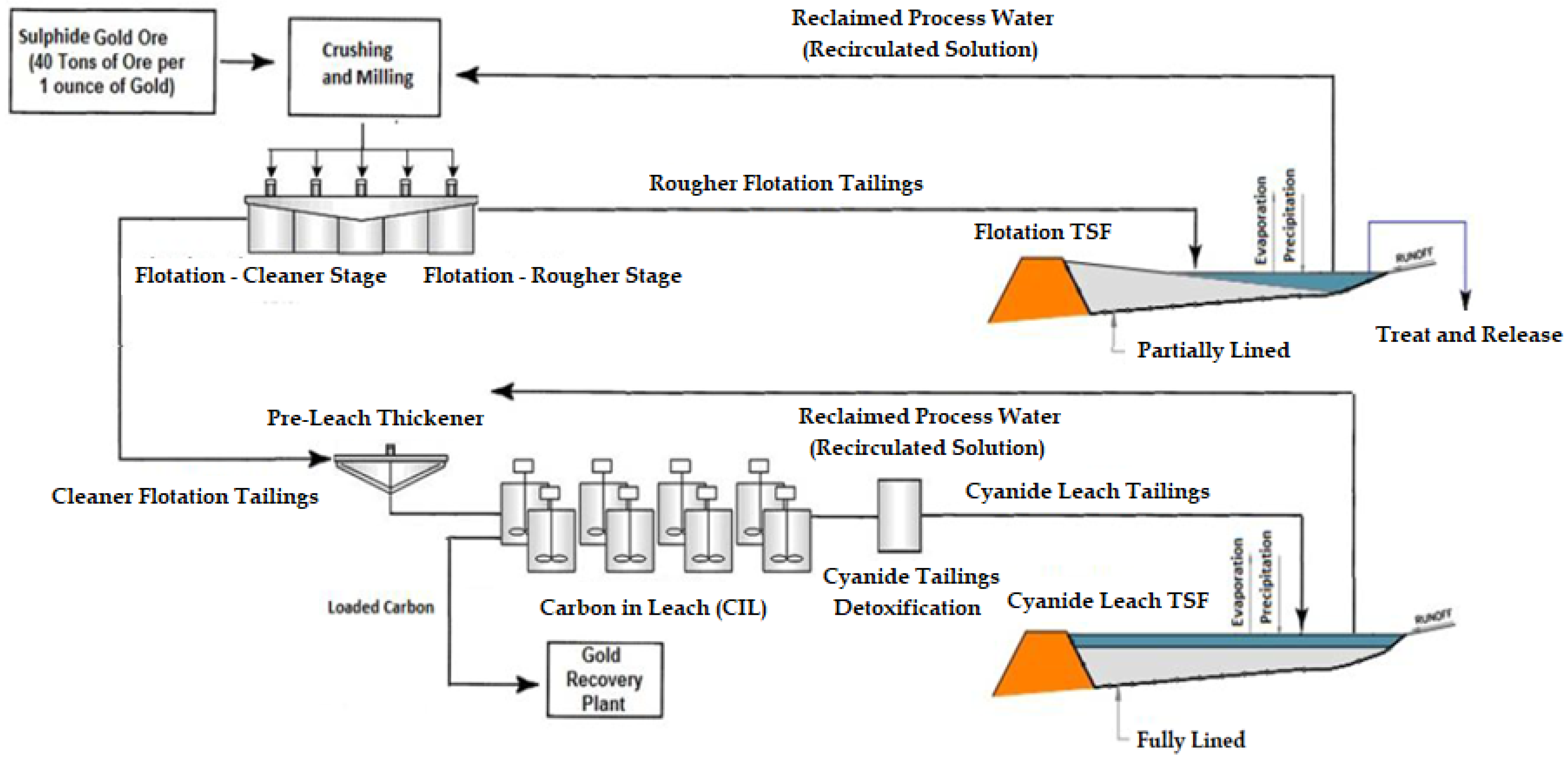
  • Management of Gold Tailings Storage Facilities
The TSFs are the final waste impoundment for the flotation and cyanide leach tailings, and the settling basin for the mill process water. The correct operation of a TSF allows it to recycle water from the grinding and leaching circuits. The dimension of the TSF is based upon the total quantity of tailings generated over the life of the mine, the solid–liquid separation time required, and the adequate management of process water (contact water with tailings) to be kept on hand. In some cases, the possible water volume from a storm event (non-contact water) needs to be considered. The ground sulphide ore and mill water makes the slurry, which is beneficiated by a physical–chemical separation process (flotation). During the rougher stage of flotation, mine tailings without cyanide are produced and impounded in a flotation TSF (Figure 3), while concentrates are conducted to a cleaner stage of flotation. At this stage, typically sodium cyanide is added along with air and/or oxygen, which are catalysts for the chemical reaction of gold and silver [17]. Mine tailings produced from gold cyanide milling operations contain traces of: (i) residual cyanide; (ii) spent cyanide solution; (iii) and solubilized metal–cyanide complexes, which can be toxic for nature and humans [4,17]. Considering these issues, cyanide tailings detoxification is incorporated in the process previous to tailings deposition in the TSF.
Additionally, cyanide-leach TSFs are typically fully lined: a GCL-geotextile–geomembrane liner is placed at the upstream face of the dam and impoundment to prevent seepage through the impoundment [4,17]. An example of this process is found at the Tambomayo gold mining project located in Arequipa, Peru, where mine tailings are disposed into a TSF fully lined with a geotextile–geomembrane system to prevent seepage and leakages to the environment (Figure 4).
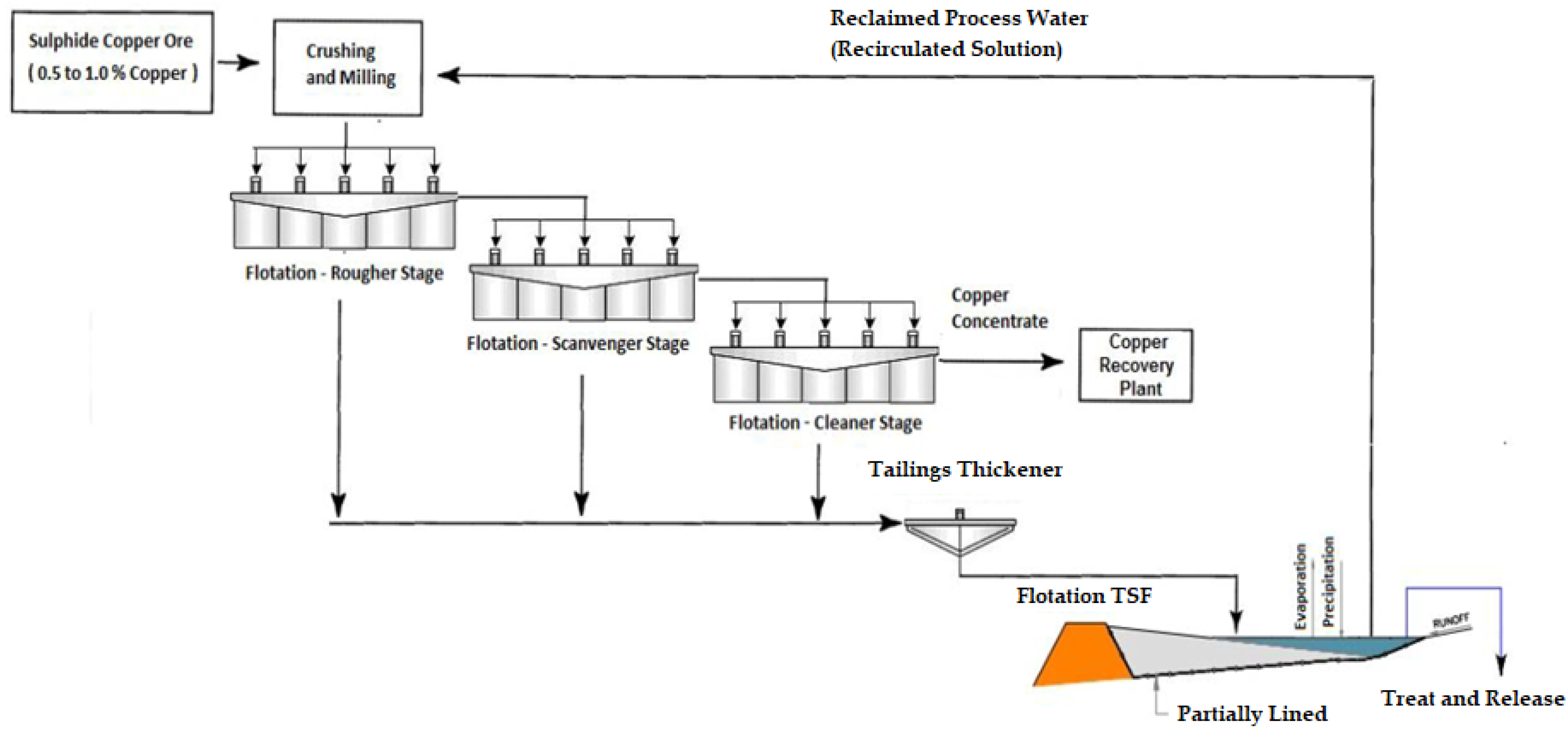
  • Management of Copper Tailings Storage Facilities
Conventional flotation cells are applied in sulphide copper mining and consist of a tank with a mechanical agitator device made to disperse air into the ore slurry, as is presented in Figure 5, assembled typically in a diverse-stage circuit, with rougher, cleaner, and scavenger cells. Lastly, the copper concentrate is conducted to a metallurgical plant, while mine tailings are thickened and conducted to the TSF for long-term storage [4].
In the past, management of mines made the storage as cheap as possible, which led to the development of the upstream dam construction method, but accidents at the El Cobre tailings dam in Chile [18] and Amatista tailings dam in Peru [19] resulted in the upstream dam construction method being banned in both countries. At present, most of the TSFs dams are constructed by the centerline and downstream construction methods, because of seismic stability issues. Copper TSFs are typically partially lined [11] to mitigate infiltration through the foundation and the TSF dam. A cutoff trench, plastic concrete slurry wall and grout-curtain system are installed along the upstream toe of the dam, and a geotextile–geomembrane liner system is placed at the upstream face of the dam. This means that TSF dams have a continuous impervious layer running all along their upstream face from the bottom cutoff trench, which waterproofs the riverbed [4].
An example of this process is at Los Pelambres copper mine, located in Salamanca (Chile). There, mine tailings are disposed into the Los Quillayes TSF, which is partially lined with a geotextile–geomembrane system in order to prevent seepage and leakages to the environment (Figure 6). This dam was constructed with cycloned tailings sand and has a final height of 198 m.

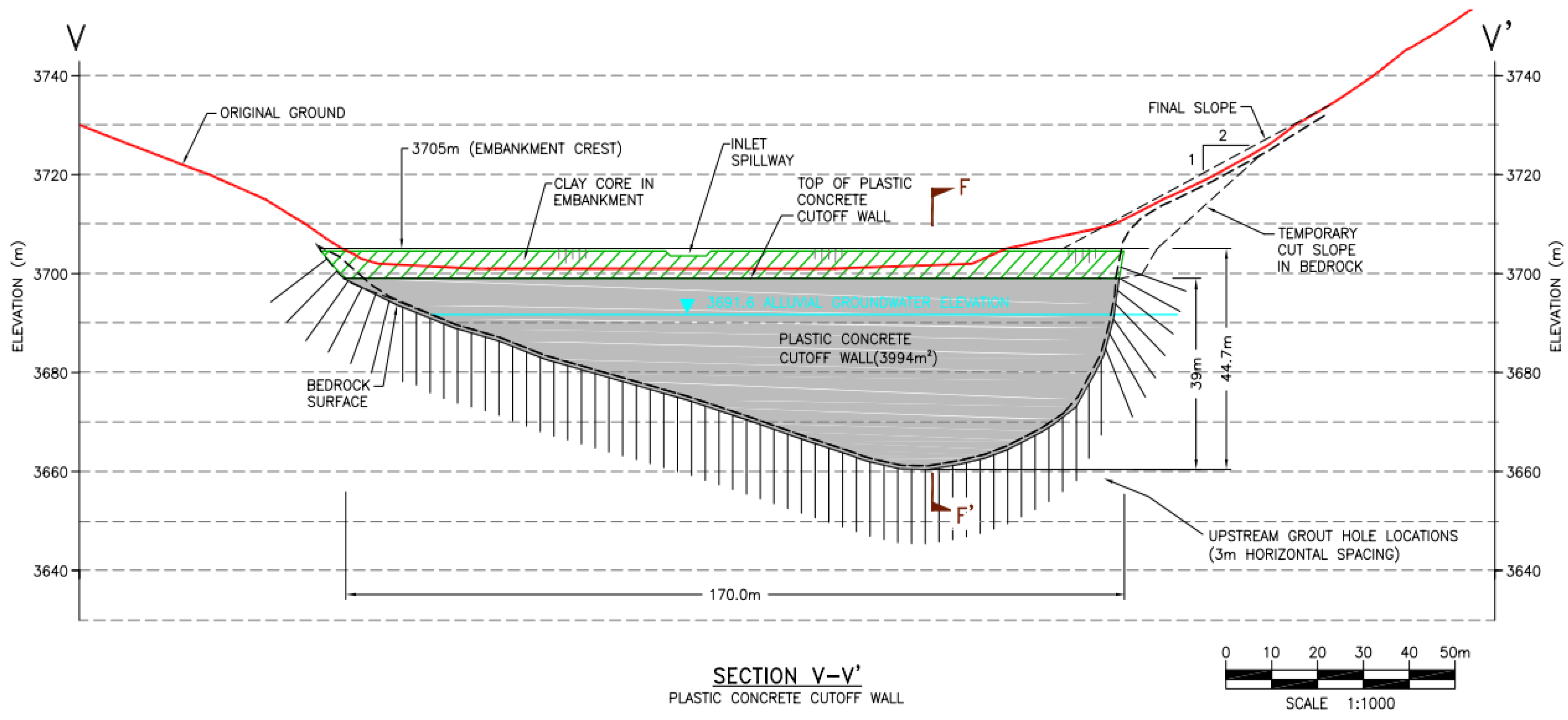
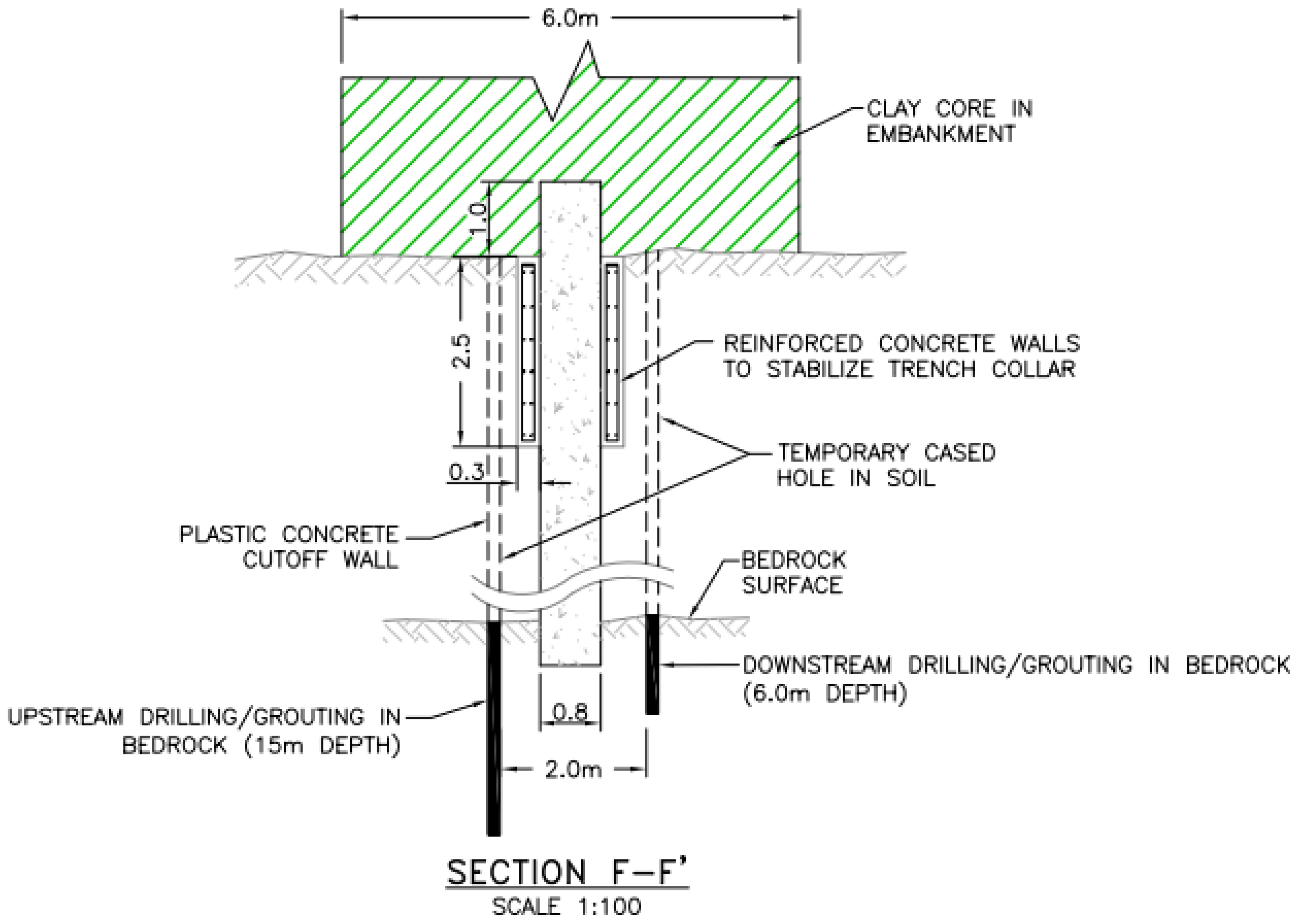
2.2.2. Cutoff Trench, Slurry Walls, and Grout Curtain Systems

Hydraulic barriers are built below the TSF and consist of cutoff trenches, plastic concrete slurry walls, and grout curtains. These control systems are installed: (i) underneath the upstream portion of a TSF dam constructed by the downstream method, and (ii) the central portion of a TSF dam constructed by the centerline method; they are not compatible with upstream TSF dams. When considering hydraulic barriers, an adequate water-quality monitoring program is needed [11,12,20,21].
Cutoff trenches, usually 1.5 to 6.0 m in depth, are the most widely used kind of hydraulic system for TSF dams, especially in terrains with big quantities of natural fine soils. Pumping may be necessary in the construction phase of cutoff trenches considering the presence of ground water. An example of cutoff trenches is shown in Figure 7.
Plastic concrete slurry walls are built in terrains with a level of morphology and containing fine-grained or saturated soils. These civil works are not adequate with fractured bedrock elements. Plastic concrete slurry walls are built by creating a trench to a zone of low-hydraulic conductivity material and then installing the plastic concrete or with a soil/bentonite slurry in the trench. Depths average 12 m and hydraulic conductivity can be obtained as low as 10−7 cm/sec as in a clay material [11,12,20,21].
Grout curtain systems used as a barrier to seepage fluxes are made of: (i) cement, (ii) silicate materials, or (iii) acrylic resins. Grout curtain systems are limited to sites with fractured rock and can be allowed to depths of 30 m. Permeability registered can be as low as 10−8 cm/s [11,12,20,21].
To guarantee the impermeability of the rock under a plastic concrete in a slurry wall–grout curtain system, an additional project should be considered that consists of a waterproof curtain based on injections of cement–bentonite grout to a depth such that it provides sufficient guarantees of the impermeability of the whole system (see Figure 8 and Figure 9). For the above, the background of drilling and infiltration tests will be studied in order to recognize in depth the quality of the foundation rock and thus define the depth of the impermeable grout curtain. According to the results, the grout curtain can be designed with one, two or three injection lines. If considered necessary based on the data obtained, the execution of complementary explorations within the first exploration line would be proposed to specify the depth of the injections.
The injections of the waterproof curtain must be carried out taking the following criteria as a guide.
  • Perforations: The perforations for the injection curtain will be made with rotary-percussion equipment or rotary probes, in the places established in the project, always using clear water as a lubricating and dragging fluid. Its minimum diameter in rock will be 50 mm for rotary percussion and HQ3 for rotation with core extraction. To cross the fluvial fill, the drilling must consider the placement of casing pipes to the rock and thus ensure a controlled injection process;
  • Water: The water used in the injection works, which may be available in the area or brought from another place, must be clean, with a pH close to neutral and comply with the standard established for mixing water for cement mortars and Portland concrete;
  • Cement: The cement used in injections must be pozzolanic in order to guarantee its resistance to the aggression of contact waters, have a Blaine specific surface of the order of 5000, must not present lumps or foreign matter, and have a manufacturing age of less than three months;
  • Bentonite: The bentonite to be used must be sodium and have a liquid limit greater than 250% and a plasticity index greater than 200%.
Some examples of different configurations of cutoff trench–grout curtain systems in mining tailings storage dams are presented in Figure 10, where it is possible to see a central core-type dam, a downstream core dam, and a rockfill dam with an upstream liner.

2.2.3. Slimes (Fine Fraction of Mine Tailings)

Tailings impoundments were a good field for experimentation since—as opposed to water dams—with these, the service of the geomembrane is limited in time, because during the TSF’s operation, the geomembrane is covered with tailings in the TSF reservoir zone discharged from the spigot located along the dam crest, and the supernatant water pond forms far away from the dam [22]. The disposal of non-dewatered mine tailings from the TSF dam produces the mine tailings beaches which typically have a disposal slope. It is considered that the progressive covering by the mine tailings acts as a seal that decreases leakages from eventual tears generated [23]. Considering the cycloned tailings sand dams, slimes are discharged from the dam crest into the TSF reservoir zone. Slimes are very fine material, have a low disposal density and retain a great percentage of water. This process implies in higher water losses trapped in voids of slimes, with a very low hydraulic conductivity of about ~10−6 cm/s [24]. This tailings discharge method allows a high freeboard, and wide beach distances achieved at TSFs are in the order of 500 m. In order to mitigate infiltration through the TSF dam foundation, a cutoff trench, plastic concrete slurry wall, and grout–curtain system can be built along the upstream toe of the dam to collect the seepage. A geosynthetic liner composed of a geotextile and geomembrane is installed at the upstream face of the cutoff trench (see Figure 11), thus providing the dam with a continuous impervious layer running all along its upstream face, from the bottom cutoff trench, which waterproofs the riverbed.
The seepage collection sump is an excavation lined with geosynthetic and geomembrane material to store filtrations. It allows the filtrations collected by the drainage system to be stored and its mission is to prevent any type of leaks, and is located downstream of the toe of the dam. The seepages are driven through pumping that recirculates them to the tailings deposit water pond, and then returned to the mill for reuse in the metallurgical process (see Figure 12).

3. Types of Geotextile and Geomembrane Used in Tailings Storage Facility Dams

3.1. Geosynthetic Base Layer—Geotextiles

The type of geotextile commonly used at the upstream face of dams at TSFs is a nonwoven, needle-punched geotextile. These materials are manufactured from the fibers of polypropylene polymers, and are highly durable and resistant to attack by chemicals, ARD (acid rock drainage), and bacteria [25].
The geotextiles manufactured in this process have good mechanical benefits, high elongation, which gives them adequate site suitability, excellent properties for protection (often referred to as the cushion effect), and very good filtration and separation functions [26].
Their main function is to provide cushion properties for the upper liner layer of geomembrane [27].

3.2. Geosynthetic Liner Layer—Geomembranes

The most common types of geomembrane materials used in TSFs include: polyvinyl chloride (PVC), high-density polyethylene (HDPE), and linear-low-density polyethylene (LLDPE) geomembrane liners. These liners are available in smooth and rough textures, as well as in a white, black, and green color, for use in different applications [27,28].
A PVC liner (flexible and easy handle) may require as little as 20% of the field seams required by a HDPE liner (tough and nonflexible) [27,28].
Textured HDPE liners were developed to compete with the slope-stability characteristics of smooth PVC, much as LLDPE liners were developed to compete with the flexibility characteristics of PVC [27,28].
The selection of geomembrane type depends on cost; more flexible geomembranes can improve the liner strength and puncture-resistance of the liner system [27,28].
A rigorous QA/QC plan needs to be applied at the geosynthetics installation stages. It is also necessary to have manufacturing quality control/assurance (MQC/MQA), and construction quality control/assurance (CQC/CQA), to ensure the compliance of manufacturers and installers [27,28].
The following tables show a characterization of geotextiles and geomembranes commonly used in Chile and Peru mining in upstream face dams as a TSF liner (See Table 2 and Table 3). Some physical properties are considered: strength/tensile properties, flow properties, and durability.
It is recommended to install a cushion comprising a nonwoven, needle-punched geotextile layer below the geomembrane to prevent punctures. In some cases when the HDPE or LLDPE geomembranes are exposed to UV rays for several days, it is recommended to install a sacrificial, nonwoven geotextile layer over the geomembrane to provide UV ray protection. The following Table 4 shows a geomembrane liner design matrix.

3.3. Geomembrane Liner Leakage Rates

No geomembrane liner is absolutely impermeable. Therefore, a zero leakage rate through a single geomembrane is impossible to achieve, and it should not be specified, and should not be a regulated requirement. In the USA, the philosophy is that all individual geomembrane liners leak; hence the use of double geomembrane lining systems. These do not leak provided a hydrostatic head is not allowed to build up on the secondary (lower) liner. Giroud [39,40] has shown that water vapor diffuses through an HDPE geomembrane, without any holes, at the rates (liters per hectare per day—lphd) shown in Table 5.
The presence of holes in the geomembrane leads to the leakage flow rate increases shown in Table 6. Therefore, a 1 mm HDPE geomembrane, again without physical holes, under a 300 mm hydrostatic head will “leak” at a flow rate of 0.8 L per day (lpd). In this case, the leakage flow rate through a 2 mm diameter pinhole with a 300 mm head is 400 L per day (lpd). As the head increases to 3 m, the leakage flow rate becomes 1300 L per day (lpd).
Electrical leak location surveys, performed by now on several hundred geomembrane lining systems throughout the world, typically show 2 to 12 leaks per 10,000 m2 to be present in high- to low-area geomembrane liners on which state-of-practice CQA has been performed [39,40]. These leaks vary from pinholes at T-seams to bulldozer blade gouges as long as 1 m at the toes of slopes.

4. Geosynthetic Solution Applications in Tailings Storage Facility Dams

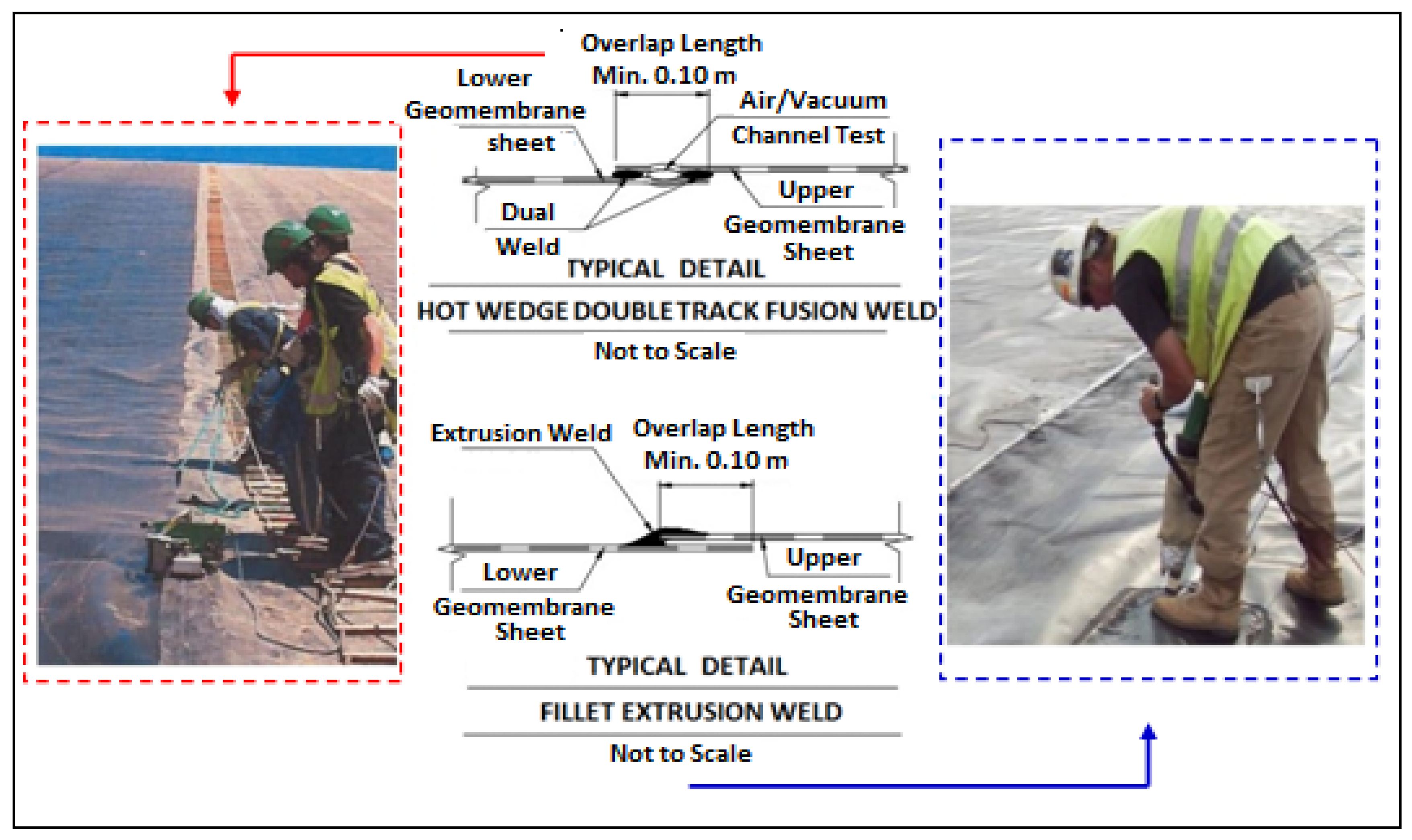
4.1. Geosynthetic Constructability Issues

Mining operations in Chile and Peru are placed mainly in mountainous areas of the Andes Range, mostly in the semiarid to hyperarid climate conditions. Due to the severe climate and adverse topographic conditions, the construction of TSFs presents extreme challenges, considering geosynthetic installation procedures in complex topographies, difficulties in sourcing specialized contractors, and demanding strict schedules.
The typical geomembrane sheet installation in a TSF dam requires grading slopes not higher than 2H:1V (see Figure 13). In order to adequately develop the system panel staging plan of the liner, the geosynthetic contractor should have a clear understanding of the predominant wind direction(s) and consider that in some cases the dams may be more than 50 m high (starter dams). Under these extreme topographical characteristics, the installation of sandbags to secure the geomembrane sheet static position is necessary.
The geomembrane sheets are unrolled down the dam slope as a first step. Then in a second step, the geomembrane sheets are cut to the appropriate length to cover the inclined dam slope. In a third step, the geomembrane sheets are joined by manual thermofusion weld seaming along the dam slope. Then, the geomembrane sheets are joined by manual extrusion weld seaming along the length of the dam [41]. As a final step, it is necessary that all welds and geomembrane sheets be inspected using industry-accepted QA/QC controls and test procedures [41]. The following Figure 14 shows the typical panels-joining works used in TSFs.

4.2. Starter Dams of TSF Built with Borrow Materials

The starter dam is the initial embankment of the tailings storage facility in the start up phase, when it is required to correctly ensure the impermeability of the riverbed. For this purpose, a continuous impervious layer along the upstream face of the starter dam is usually used, as well as the installation of a cutoff, plastic concrete slurry wall, and grout curtain system.
A low-permeability layer is installed on starter dams constructed with borrow materials. This consists of a 1.5 mm flexible HDPE geomembrane bedding with two nonwoven, needle-punched geotextiles. These two geotextiles have the function of anti-puncture layers that protect it against possible puncture damage. The starter dam is constructed with horizontal 0.5 m-thick lifts of selected borrow fill material for building the body and filter layer of the dam.
Once the dam contractor has finished the first construction stage, from the cutoff and grout curtain system to the intermediate berm at mid-height level of the borrow dam, a QA/QC engineer verifies that the surface fully complies with the technical specifications. Any deviation regarding placement of the waterproofing system is immediately corrected.
In the checked areas, the geosynthetic contractor immediately starts placing a 200 g/m2 nonwoven geotextile on the silty sand filter layer, typically 1 m wide. The geotextile is commonly conveyed to the site in 4.5 m-wide × 100 m-long rolls. Then, the geotextile sheets are unrolled down the dam slope and cut to the appropriate length to cover the entire inclined dam slope. Once cut, the geosynthetic material is placed vertically along the top–bottom of the starter dam slope, with an overlapping of at least 15 cm between adjacent geosynthetic sheets. Along the overlapping, the geotextile sheets are joined by manual thermofusion seaming. Figure 15 shows a geotextile and geomembrane liner installation schematic view on a starter dam constructed with borrow materials:
Then, in the toe of the starter dam slope, the placement of geotextile and geomembrane is carried out in the cutoff, plastic concrete slurry wall, and grout curtain system. Once the installation of the anti-puncture geotextile is in progress, the geosynthetic contractor begins to place the HDPE geomembrane. The geomembrane is commonly supplied in 7 m-wide × 150 m-long rolls. The geomembrane rolls are placed along the temporary crest of the starter dam, the edge of the geomembrane sheet is unrolled to cover 2 m on the flat dam crest, and after verification of the correct alignment the sheet is completely unrolled down the slope. The geomembrane sheets are anchored in trenches at the intermediate berm of the TSF dam. Adjoining sheets overlap at least 10 cm, and are joined by thermofusion seaming. The seams are executed by a machine creating a double-track seam. A relevant aspect of this type of seam is the presence of a small channel that allows performing a nondestructive test with air under pressure. HDPE geomembrane panel joints between stages 1 and 2 are seamed by manual extrusion weld seaming along the dam’s intermediate berm. All the executed seams are tested. Figure 16 shows the typical geosynthetic installation schematic view described above.
After the HDPE geomembrane is anchored at the lower and upper levels, the geomembrane is protected from the wind by placing sandbags over it during the time it is exposed to the environment, waiting for the tailings to be added. Once the first construction stage has finished, a second stage starts from the intermediate berm to the starter dam crest. The dam contractor and geosynthetic contractor follow the same geosynthetic installation procedures described above. The following Figure 17 shows an installation of a 100,000 m2 geomembrane liner at the upstream face of a TSF starter dam, after the second stage of construction was complete, reaching a 60 m height.
The geosynthetic liner system thus creates a low-permeability layer running all along the longitudinal axis of the started dam from the bottom cutoff trench–plastic concrete slurry wall–grout curtain system up to dam the crest.

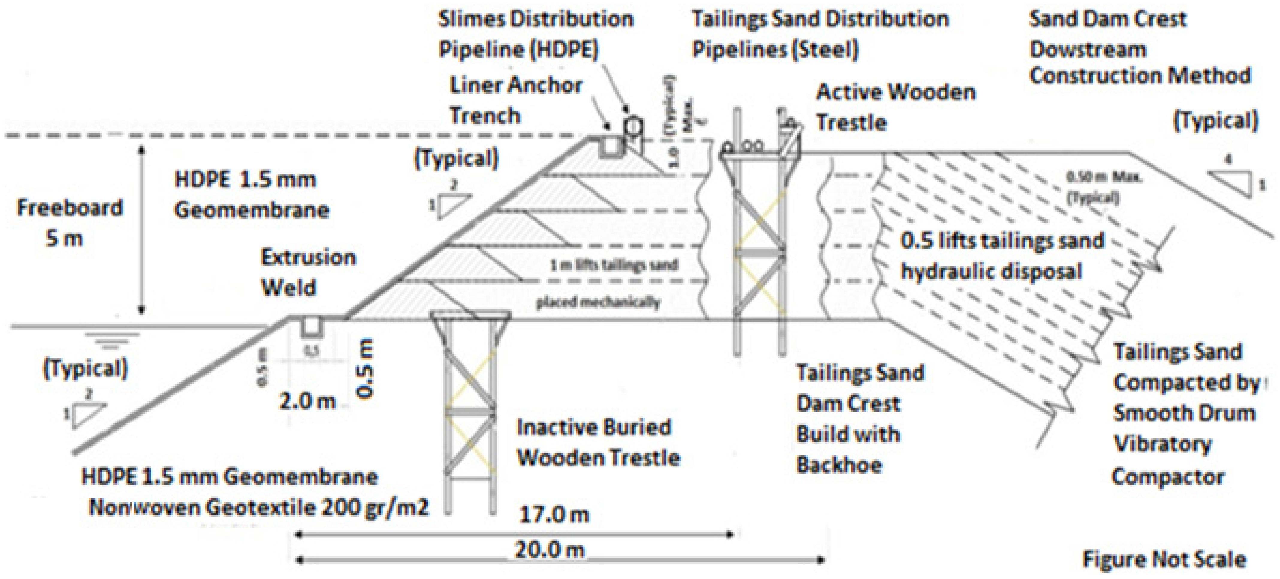
4.3. Cycloned Tailings Sand Dams

Most cycloned tailings sand dams in Chile and Peru are constructed using the centerline method and downstream method over a borrow material starter dam, using cycloned tailings sand (underflow) produced by hydrocyclones, containing no more than 18% of fines (material passing ASTM No. 200 sieve size), to develop the dam’s ultimate configuration with a 4H:1V downstream slope. The process of cycloned tailings sand dam construction involves five main steps:
  • Dispose of hydrocyclone underflow materials (cycloned tailings sand) in a loose 0.5 m thick layer;
  • Allow the deposited hydrocyclone underflow materials to drain;
  • Compact the underflow materials with smooth vibratory rollers;
  • Construct the geometry of the dam (slopes and crest width, providing adequate freeboard);
  • Install the waterproofing liner at the upstream face of the dam.
Figure 18 shows a schematic view of cycloned tailings sand dam construction. The cycloned tailings sand obtained in a hydrocyclone station is hydraulically transported by pipelines along the dam crest and discharged through spray bars that are mounted on the delivery pipeline, installed on a wooden trestle system (Figure 19). The dam is raised in lifts of compacted cycloned tailings sands, being mechanically compacted by smooth vibratory rollers, to achieve 95% of the maximum dry density per ASTM D698 (Proctor Standard Test). A minimum of 5 m of freeboard between the dam crest elevation and the elevation of the impounded tailings (slimes) against the dam must be maintained at all times.
To provide an appropriate site for construction maneuvers, the crest of the cyclone tailings sand dam must at least have a width equivalent to 20 m and a slope upstream of the dam equivalent to 2H:1V. Thus, it is possible to install the wooden structure for the placement of the cyclone tailings sand pipes, as well as having a sufficient width for the circulation of construction and maintenance vehicles. In addition, it is necessary to install an anchorage trench for the geotextile–geomembrane lining that will be placed on the slope upstream of the dam. Finally, a place is needed for the slimes pipe system.
The construction sequence for the dam overgrowths is the following:
  • Is necessary to install a new wooden structure to assemble the sand transport pipes;
  • The louver discharge pipe must be relocated;
  • An anchor trench for the geosynthetic materials must be built along the entire crest of the dam;
  • A new roll of geotextile and geomembrane needs to be installed on the slope upstream of the dam.
The following construction procedures show:
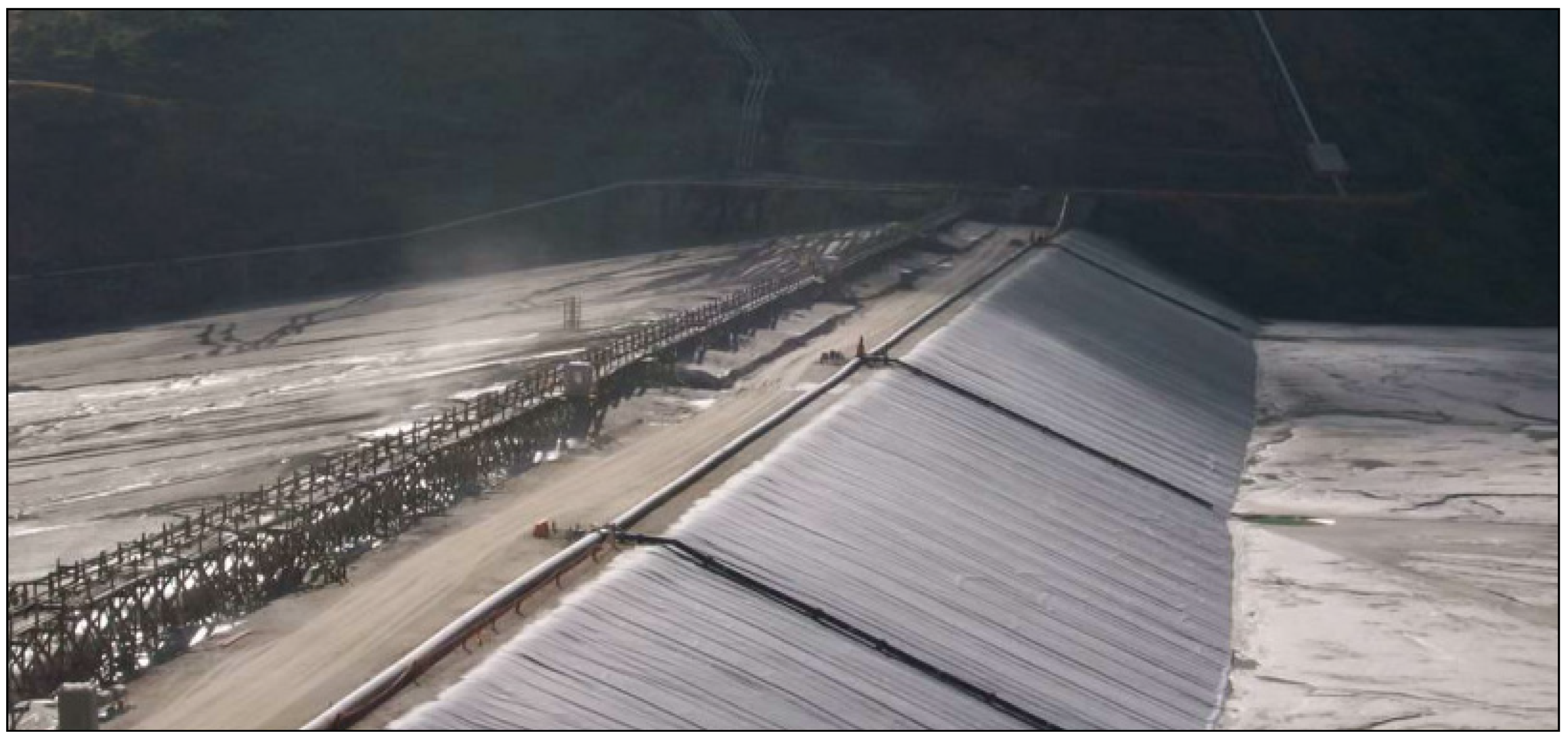
  • A typical cycloned tailings sand dam crest with wooden trestles for tailings sand pipelines, slimes pipeline with spigots, and geosynthetic liner (Figure 20);
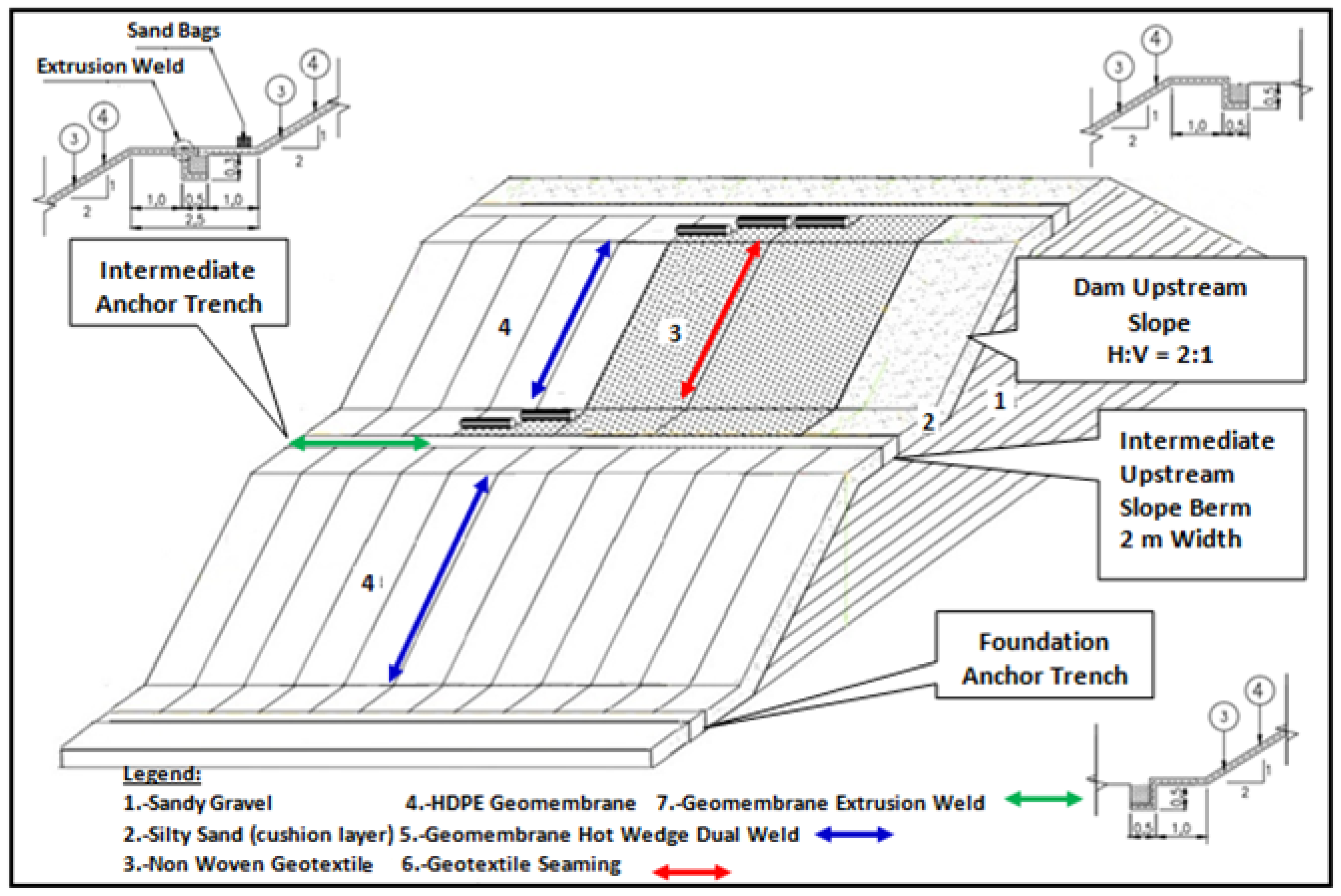
  • A geosynthetic installation schematic view of a cycloned tailings sand dam using the downstream construction method (Figure 21);
  • A construction procedure in cycloned tailings sand dam crest (Figure 22).

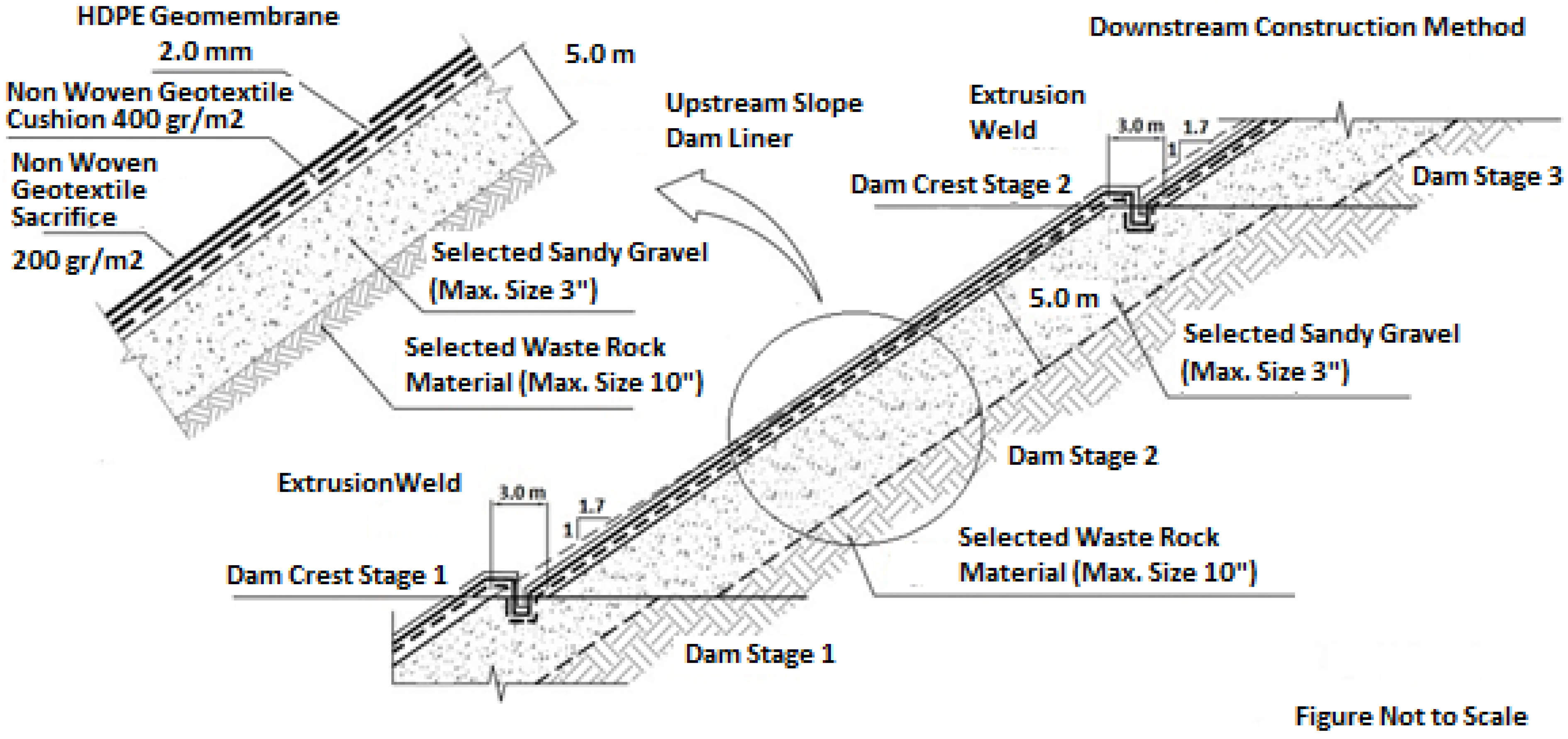
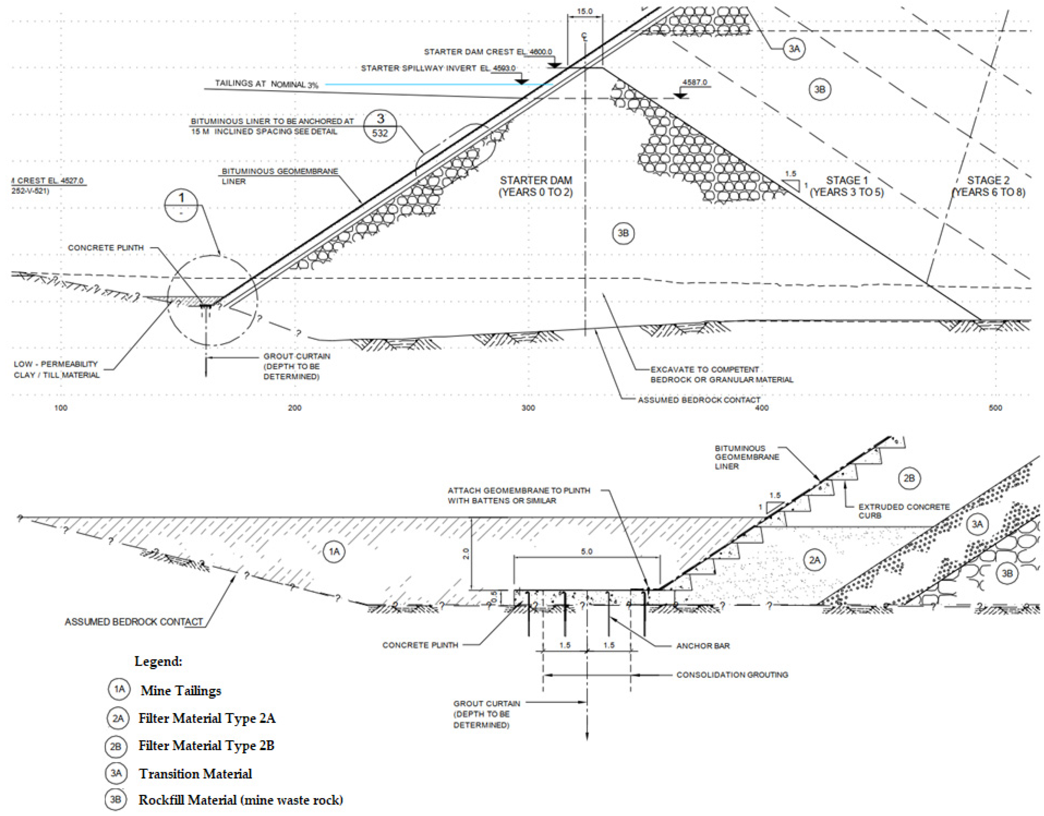
4.4. Mine Waste Rock (Rockfill) Dams

Some mining operations use the mine waste rock from the stripping mine phase, or from mine waste rock dumps, for building a rockfill dam for their TSFs (see Figure 23). This solution is adopted usually when:
  • The mining waste rock materials have no potential to generate AMD (acid mine drainage);
  • There is a lack of borrow material availability and high waste rock/ore ratios;
  • There are short hauling distances between the waste rock sources and the TSF site;
  • There are flatter terrains, such as in the Atacama Desert areas, where mines need to build TSFs with a ring-dike configuration with large dams (more than 4 km long). This presents difficulties regarding transport and construction of cycloned tailings sand dams.
In the mine waste rock dam section, zoning is needed with different materials, with the objective to accomplish with the piping and filter criteria [45]. This design criteria can be achieved by varying soil layers specifications thickness and the degree of compaction. Rockfill material (mine waste rock) with a maximum particle size of 25.4 cm is commonly placed in 1 m lifts, expected to generally require no processing except for the removal of oversized particles. This lift zone will be spread by a dozer DR10 and compacted with a vibratory drum roller or by the mine haul fleet. A filter layer is built between the tailings and the rockfill material on the upstream face of the dam. In order to function as a filter, this zone consists primarily of silty sand-sized particles, with some gravel and minimal fines content. These materials will be placed in 0.3 m lifts (Figure 24).
A low-permeability core of 2 mm HDPE geomembrane cushioned by one 400 g/m2 anti-puncture, nonwoven geotextile is placed on the upstream face of the dam. The nonwoven geotextile protects the geomembrane against possible puncture damage by the dam materials. The following Figure 25 shows typical detail of a geotextile–geomembrane liner on the upstream face of a rockfill dam.

5. Discussion

5.1. Lessons Learned Considering Experience

The use of geosynthetics depends on many factors, such as: material of the dam, type of mine tailings, and climate and topographic conditions, among others. The following paragraphs include some key issues that need to be considered in the design, construction, operation, and closure of TSFs.

5.1.1. Advantages

The following aspects are considered advantages in the use of geosynthetics in TSF dams.
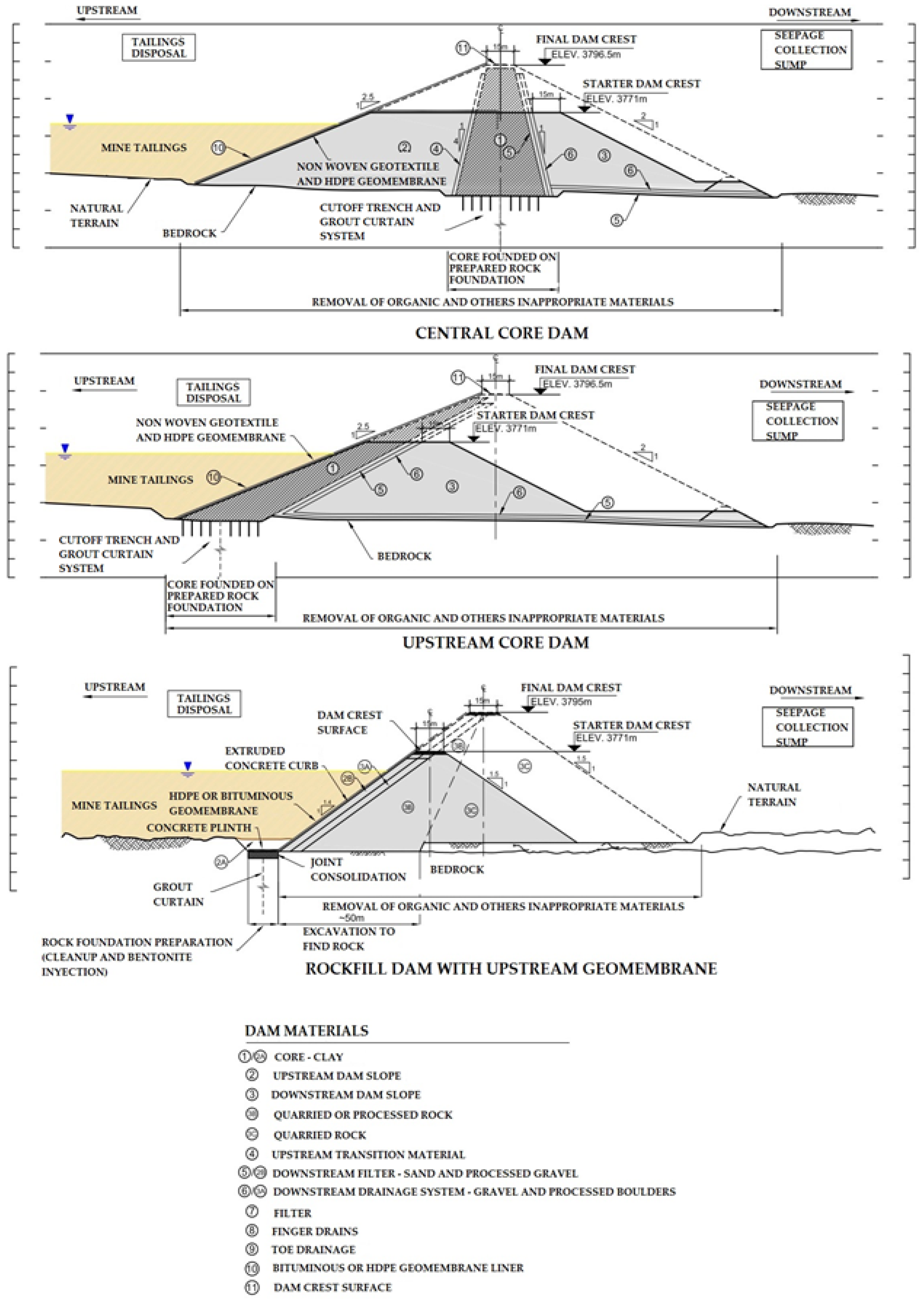
  • No use of clay layers: geotextiles and geomembranes allow a chance to minimize the use of costly clay soil filter materials in the dam. The geomembrane lining system is adequate, because it is flexible and resists differential settlement, allowing control of the hydraulic gradients, and providing both physical and environmental containment of tailings [46,47,48];
  • Simplicity: geotextiles and geomembranes help in the installation process so that the overall construction schedule period is minimized [46,47,48];
  • Safety: geosynthetics increase the undrained shear strength of the dam with a hydrostatic loading during a seismic event, providing an acceptable factor of safety that is safer than the concrete-faced rockfill dam alternative [46,47,48];
  • Long-term performance: geotextiles and geomembranes offer better effective performance against acid-mine drainage (AMD) generation, and their structural properties do not change due to the effects of oxidization and leaching caused by sulfide-rich mine tailings [46,47,48].

5.1.2. Disadvantages

The following aspects are considered disadvantages in the use of geosynthetics in TSF dams.
  • Risk to puncture: geomembranes are more susceptible to damage caused by differential deformations, settling of the support surface, or sensible when exposed to small, sharp protrusions [46,47,48];
  • Water and mine tailings loading in order to provide adequate geotextile–geomembrane systems resistance: it is necessary to consider water loading, excessive mine tailings confining pressures [46,47,48];
  • Susceptible to climate change: severe temperature changes cause thermal material contraction. Geotextiles and geomembranes can be affected by wind and can be damaged by UV rays if they are permanently exposed to them [46,47,48].

5.2. New Trends

Bituminous geomembrane (BGM) liners are a bituminous waterproofing system, unique in terms of their 5.10 m width. A BGM combines an elastomeric bitumen-based binder and an internal structure made from nonwoven polyester geotextile; it is designed to guarantee excellent mechanical and chemical resistance over the long term. Some key benefits are:
  • Resistance to aggressive environments even without adding an anti-puncture geotextile;
  • Compatible with all subgrades and covering material (hot-mix, asphalt, concrete, stone, gravel);
  • Excellent resistance to ageing (UV, weather, biological agents and oxidation);
  • Suitable for extreme weather conditions (rain, wind, extreme cold (–40 °C));
  • Remarkable dimensional stability and flexibility guaranteeing permanent support with the supporting ground;
  • Durability under real conditions exceeding 40 years;
  • Friction angle up to 34°, greater than any other geomembrane;
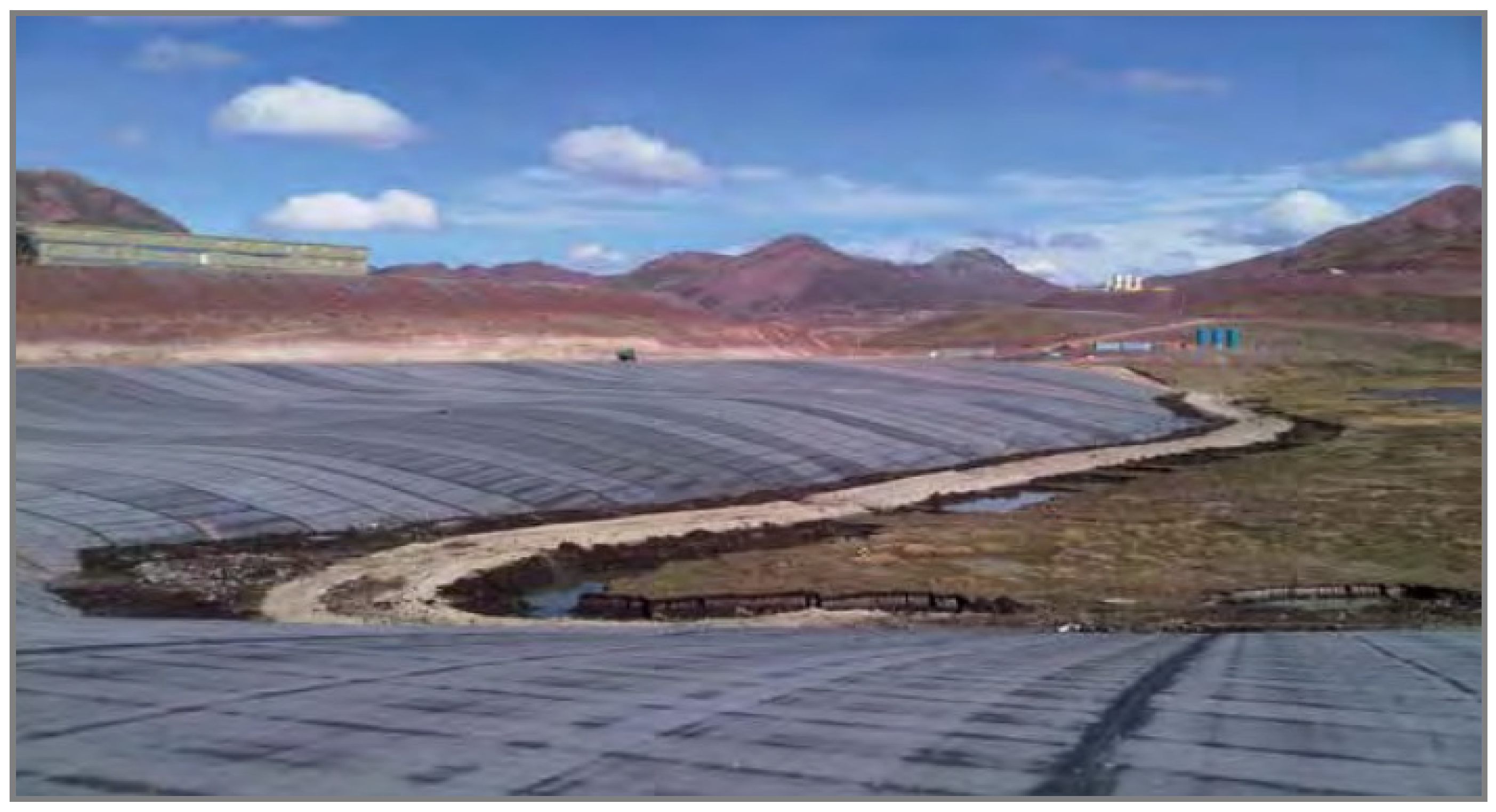
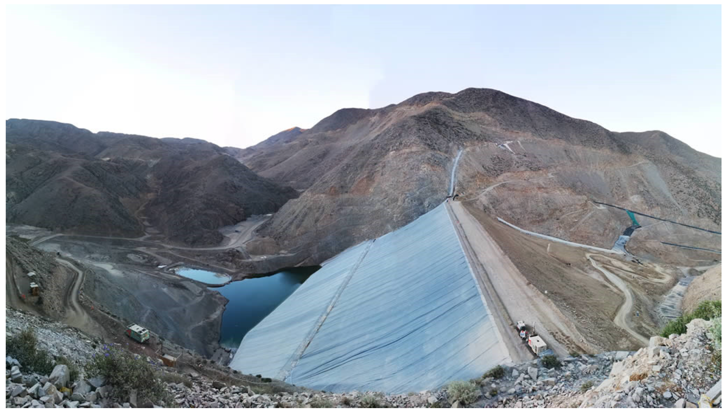
  • Figure 26 shows an example of application of BGM in the Toromocho TSF project in Peru.
An alternative bituminous geomembrane (BGM) liner is implemented in mine operations around the world and shows the low permeability of this type of geomembrane in cases of dams with gentle slopes. Figure 27 shows an example of construction details of implementation of a BGM liner.
The joints between the BGM sheets are welded at a high temperature using a simple gas torch, ensuring an additional advantage over other types of geomembranes. The installation of BGM panels is a fast, controlled activity, considering that special equipment is not required.
A new technology emerges in the era of industry 4.0, which corresponds to intelligent geosynthetics with the use of fiber optics, in order to acquire real-time data on deformations, displacements, and stresses of the tailings dam [49,50].
The intelligent geotextile can be considered as a sensor, which can measure temperature changes in the optical fiber in order to detect leaks together with the drainage properties of the geosynthetic. The filtration characteristics of the geotextile also allow the stability of the soil by inhibiting the process of internal erosion.
On the other hand, an advantage of considering a geotextile as a sensor is its high coefficient of friction properties when interacting with the ground. This friction interface also allows for the transfer of soil displacements from the geotextile to the fiber optic line [49,50] (see Figure 28).

5.3. Hydrogeological Aspects to Note

Tailings dams in Chile and Peru are usually located in mountain ranges, or surrounded by island hills, due to the fact that the outcropping rock forming a topographical height acts as a natural dam, reducing the amount of artificial embankment that will be necessary to build for the construction of the reservoir. The permeability of the basement rocks will be controlled by the density of fractures and their connectivity [50]. Although current regulatory frameworks already require structural studies to characterize the permeability of these rocks, these can underestimate the hydraulic conductivity through the rock. Eventually, a flow of contacted process water may infiltrate through the secondary permeability of the fractured-rock aquifer, which is normally connected to the overlying alluvial aquifer in the surrounding areas of the dam [51,52,53,54]. In addition, the possibility of seepage will increase as the tailings height grows (confining pressures increases), and the exposed rock area covered by tailings increases. In this context, another advantage of geomembrane liners is that they have the feasibility of being installed, not only in the dam, but along all exposed rock surfaces on the sides of the tailings storage facility, thus reducing the contact of process water with rock walls, which are susceptible to presenting permeability due to fractures or other structural weaknesses (Figure 29). Therefore, the widespread installation of geosynthetic liners is a guarantee of protection against infiltrations through fractures in the rock, being an economic measure and easy to develop [51,52,53,54].

5.4. Final Remarks

The following key technical, design, and construction aspects are considered in the practice.
  • Types of geosynthetic materials: many types of geomembranes have been used in TSFs, including: polyvinyl chloride (PVC), high-density polyethylene (HDPE), and linear-low-density polyethylene (LLDPE). The criteria for the selection of the geosynthetics are based on technical environmental and cost issues;
  • Thickness and performance of geosynthetics: the current state-of-the-art practices to prevent leakage, to provide durability, and to enhance resistance to UV rays;
  • Types of cushion layers for geosynthetic materials: the criteria used to choose materials on which to place geomembranes, with a focus on limiting damage by puncturing;
  • Constructability: a key aspect is the installation of the geosynthetics on the upstream face slope of the tailings dams, taking into consideration the mine tailings discharges (spigots), wind, and rainfall conditions;
  • QA/QC: quality assurance and quality control—the geosynthetic quality is monitored at all stages of design, manufacturing, construction, and operation;
  • Sustainability: the application of geosynthetics is environmentally friendly because (i) they minimize the environmental impacts of borrow material pits and quarry operations by providing filters, grading the materials in the dam, and (ii) they mitigate tailings dam seepage.

6. Conclusions

At present, management of the mining tailings stored in the territory must be carried out in a responsible and controlled way, in order to avoid any negative impact to the ecosystem and surrounding communities. The implementation of geosynthetic liners and cutoff trench–plastic concrete slurry wall–grout curtain systems allow the reduction and control of seepage flows from the TSFs. To ensure the quality and efficiency of these seepage control systems, it is necessary to carry out an appropriate design, adequate construction, and permanent monitoring during the operation, closure, and post-closure stage of the TSF.
Regardless of the mining tailings management with the best available technologies (BATs) being considered (conventional tailings, thickened tailings, paste tailings, or filtered tailings), seepage control systems should always be implemented, as all types of tailings release contact water, either in smaller or larger quantity.
Management of gold mining tailings with the use of sodium cyanide reagents requires a complete lining with a geomembrane in the area of the tailings deposit reservoir, according to the code for the management of tailings with cyanide residues. On the other hand, management of copper mining tailings requires at least partial lining with a geomembrane in the area of the upstream face of the dam.
Although geomembrane liners are not completely impermeable, they are nearly waterproof when compared to other materials like clay soils. The main function of geosynthetics on TSFs is to serve as a liner layer between different materials to mitigate eventual leaks that may occur. The covering by the mine tailings acts as a seal that attenuates seepage derived from eventual perforations or tears in the geomembrane liner generated during its useful life.
There is a possibility that, by applying variable environmental thermal conditions considering climate change, the geomembrane may change its properties so that it no longer provides long-term resistance to the physical and chemical factors to which it will be exposed. In this case, at the joints, the risk of infiltrations is somewhat high. Experimental studies are recommended regarding the comparison of lifetime of the welded areas versus the geomembrane sheet.
The experience of Chile and Peru, which have the highest tailings dams in the world, and climate conditions ranging from wet to hyper arid, complex topography, and exposure to seismic events, represent a worldwide example of state of the art practice in engineering and construction of this type of civil works.
For these reasons, the use of geosynthetics in TSFs in environmentally responsible mining is growing daily. Moreover, this is encouraged by regulatory frameworks that support environmentally friendly mine tailings management solutions that control tailings seepage and reduce environmental impacts.

Author Contributions

Conceptualization, C.C. and E.A.; formal analysis, C.C.; investigation, C.C.; resources, E.A.; writing—original draft preparation, C.C.; writing—review and editing, C.C. and A.P.; visualization, C.C. and A.P.; supervision, E.A. and P.V. All authors have read and agreed to the published version of the manuscript.

Funding

The research is funded by the Research Department of the Catholic University of Temuco, Chile.

Data Availability Statement

The data presented in this study are available on request from the corresponding author.

Conflicts of Interest

The authors declare no conflict of interest.

Abbreviations

TSFTailings storage facility
BATsBest available technologies
AMDAcid mine drainage
CwSlurry tailings solids content by weight
mtpdMetric tonnes per day
HDPEHigh density polyethylene
LLDPELinear low-density polyethylene
PVCPolyvinyl chloride
BGMBituminous geomembrane
GCLGeosynthetic clay liner
maslMeters above sea level
UV raysUltraviolet rays
QA/QCQuality assurance and quality control
MQA/MQCManufacturing quality assurance/control
CQA/CQCConstruction quality assurance/control
lphdLiter per hectare per day
lpdLiter per day

References

  1. Cacciuttolo, C.; Valenzuela, F. Efficient Use of Water in Tailings Management: New Technologies and Environmental Strategies for the Future of Mining. Water 2022, 14, 1741. [Google Scholar] [CrossRef]
  2. Cacciuttolo, C.; Atencio, E. An Alternative Technology to Obtain Dewatered Mine Tailings: Safe and Control Environmental Management of Filtered and Thickened Copper Mine Tailings in Chile. Minerals 2022, 12, 1334. [Google Scholar] [CrossRef]
  3. Cacciuttolo, C.; Atencio, E. Past, Present, and Future of Copper Mine Tailings Governance in Chile (1905–2022): A Review in One of the Leading Mining Countries in the World. Int. J. Environ. Res. Public Health 2022, 19, 13060. [Google Scholar] [CrossRef] [PubMed]
  4. Cacciuttolo, C.; Cano, D. Environmental Impact Assessment of Mine Tailings Spill Considering Metallurgical Processes of Gold and Copper Mining: Case Studies in the Andean Countries of Chile and Peru. Water 2022, 14, 3057. [Google Scholar] [CrossRef]
  5. Edraki, M.; Baumgartl, T.; Manlapig, E.; Bradshaw, D.; Franks, D.M.; Moran, C.J. Designing mine tailings for better environmental, social and economic outcomes: A review of alternative approaches. J. Clean. Prod. 2014, 84, 411–420. [Google Scholar] [CrossRef]
  6. Franks, D.M.; Boger, D.V.; Côte, C.M.; Mulligan, D.R. Sustainable development principles for the disposal of mining and mineral processing wastes. Resour. Policy 2011, 36, 114–122. [Google Scholar] [CrossRef]
  7. Cacciuttolo Vargas, C.; Pérez Campomanes, G. Practical Experience of Filtered Tailings Technology in Chile and Peru: An Environmentally Friendly Solution. Minerals 2022, 12, 889. [Google Scholar] [CrossRef]
  8. East, D.; Fernandez, R. Managing Water to Minimize Risk in Tailings Storage Facility Design, Construction, and Operation. Mine Water Environ. 2021, 40, 36–41. [Google Scholar] [CrossRef]
  9. Oberle, B.; Brereton, D.; Mihaylova, A. Towards Zero Harm: A Compendium of Papers; Global Tailings Review: St. Gallen, Switzerland, 2020. [Google Scholar]
  10. Schoenberger, E. Environmentally sustainable mining: The case of tailings storage facilities. Resour. Policy 2016, 49, 119–128. [Google Scholar] [CrossRef]
  11. US EPA. The Feasibility of Lining Tailings Ponds; U.S. Environmental Protection Agency, Office of Solid Waste: Washington, DC, USA, 1997.
  12. U.S. Environmental Protection Agency, Office of Solid Waste, Special Waste Branch. Design and Evaluation of Tailings Dams: Technical Report; U.S. Environmental Protection Agency, Office of Solid Waste: Washington, DC, USA, 1994; pp. 5–14.
  13. Fourie, A.B.; Bouazza, A.; Lupo, J.; Abrão, P. Improving the Performance of Mining Infrastructure through the Judicious Use of Geosynthetics. In Proceedings of the 9th International Conference on Geosynthetics, Guarujá, Brazil, 23–27 May 2010. [Google Scholar]
  14. Davies, M.P.; Lightall, C.; Rice, S.; Martin, T.E. Design of Tailings Dams and Impoundments. In Proceedings of the Processing Plant Design, Practice, and Control Conference, Phoenix, AZ, USA, 25–27 February 2002. [Google Scholar]
  15. Caldwell, J.; Smith, A. Material Considerations in the Design of Downstream Embankments for Tailings Impoundments. Min. Sci. Technol. 1985, 3, 35–49. [Google Scholar] [CrossRef]
  16. Cacciuttolo, C.; Marinovic, A. Sustainable Management of Thickened Tailings in Chile and Peru: A Review of Practical Experience and Socio-Environmental Acceptance. Sustainability 2022, 14, 10901. [Google Scholar] [CrossRef]
  17. Adams, M. Approaches to Cyanide Code Compliance Tailings Storage Facil. In Gold Ore Processing: Project Development and Operations; Elsevier: Amsterdam, The Netherlands, 2016; Volume 13. [Google Scholar]
  18. Dobry, R.; Alvarez, L. Seismic Failures of Chilean Tailings Dams. J. Soil Mech. Found. Div. ASCE 1967, SM6, 237–259. [Google Scholar] [CrossRef]
  19. Alva-Hurtado, J.E. Causas, Conclusiones y Remediación de Presas de Relave Colapsadas por Eventos Sísmicos. In Proceedings of the Primer Simposio Nacional de Medio Ambiente y Seguridad Minera, Colegio de Ingenieros del Peru (CIP), Lima, Peru, 18–21 May 1997. [Google Scholar]
  20. USACE General Design and Construction Considerations for Earth and Rock-Fill Dams. Eng. Des.-U.S. Army Corps Eng. 1994, EM 1110-2, 78. Available online: http://www.usace.army.mil/inet/usace-docs/ (accessed on 23 December 2022).
  21. USACE Seepage Analysis and Control for Dams. Eng. Des.-U.S. Army Corps Eng. 2005, EM 1110-2, 392. Available online: https://books.google.co.jp/books/about/Seepage_Analysis_and_Control_for_Dams.html?id=ggVSAAAAMAAJ&redir_esc=y: (accessed on 23 December 2022).
  22. McLeod, H.; Murray, L. Tailings Dam Versus a Water Dam, what is the Design Difference. In Proceedings of the ICOLD Symposium on Major Challenges in Tailings Dams, Montreal, QC, Canada, 15 June 2003. [Google Scholar]
  23. Barrera, S.; Lagas, R. Evolution in the Use of Geomembranes in Tailings Dams. In Proceedings of the 3rd Pan-American Geosynthetic Conference GeoAmericas, Lima, Peru, 6–9 May 2012. [Google Scholar]
  24. Barrera, S. Deposition Densities of Tailings in Chilean Deposits. In Proceedings of the 5th International Conference on Tailings and Mine Waste, Fort Collins, CO, USA, 26–28 January 1998; pp. 109–116. [Google Scholar]
  25. Cacciuttolo, C.; Tabra, K. Water Management in the Closure of Tailings Storage Facilities. Available online: https://www.imwa.info/docs/imwa_2015/IMWA2015_Cacciuttolo_138.pdf (accessed on 23 December 2022).
  26. Lavoie, F.L.; Kobelnik, M.; Valentin, C.A.; da Silva Tirelli, É.F.; de Lurdes Lopes, M.; Lins da Silva, J. Environmental Protection with HDPE Geomembranes in Mining Facility Constructions. Constr. Mater. 2021, 1, 122–133. [Google Scholar] [CrossRef]
  27. Tuomela, A.; Ronkanen, A.K.; Rossi, P.M.; Rauhala, A.; Haapasalo, H.; Kujala, K. Using geomembrane liners to reduce seepage through the base of tailings ponds—A review and a framework for design guidelines. Geosciences 2021, 11, 93. [Google Scholar] [CrossRef]
  28. Spagnoli, G.; Clement, F.; Zeleke Dilnesa, B.; Cao, F.; Feng, P. A new waterproofing membrane for tailings ponds. In Proceedings of the 22nd International Conference on Paste, Thickened and Filtered Tailings, Cape Town, South Africa, 8–10 May 2019; pp. 153–164. [Google Scholar] [CrossRef] [Green Version]
  29. ASTM D 698; Standard Methods for Laboratory Compaction Characteristics of Soil using Standard Effort. American Society for Testing and Materials: West Conshohocken, PA, USA, 2000.
  30. ASTM D 751; Standard Test Methods for Coated Fabrics. American Society for Testing and Materials: West Conshohocken, PA, USA, 2011.
  31. ASTM D 4595; Tensile Properties of Geotextiles by the Wide Width Strip Method. American Society for Testing and Materials: West Conshohocken, PA, USA, 2017.
  32. ASTM D 4632; Tensile Properties of Geotextiles by Grab Tensile Test Method. American Society for Testing and Materials: West Conshohocken, PA, USA, 2003.
  33. ASTM D 4884; Standard Test Method for Seam Strength Sewn Geotextiles. American Society for Testing and Materials: West Conshohocken, PA, USA, 2009.
  34. ASTM D 6392; Standard Test Method for Determining the Integrity of Nonreinforced Geomembrane Seams Produced Using Thermo-Fusion Methods. American Society for Testing and Materials: West Conshohocken, PA, USA, 2012.
  35. ASTM D 5820; Standard Practice for Pressurized Air Channel Evaluation of Dual Seamed Geomembranes. American Society for Testing and Materials: West Conshohocken, PA, USA, 2011.
  36. ASTM D 5641; Standard Practice for Geomembrane Seam Evaluation by Vacuum Chamber. American Society for Testing and Materials: West Conshohocken, PA, USA, 2011.
  37. ASTM D 6365; Standard Practice for the Nondestructive Testing of Geomembrane Seams Using the Spark Test. American Society for Testing and Materials: West Conshohocken, PA, USA, 2018.
  38. Lupo, J.F.; Morrison, K.F. Geosynthetic Design and Construction Approaches in the Mining Industry. Geotext. Geomembr. 2005, 25, 96–108. [Google Scholar] [CrossRef]
  39. Giroud, J.P.; Bonaparte, R. Leakage through Liners Constructed with Geomembranes, Part I: Geomembrane Liners. Geotext. Geomembr. 1989, 8, 27–67. [Google Scholar] [CrossRef]
  40. Giroud, J.P.; Bonaparte, R. Leakage through Liners Constructed with Geomembranes, Part II: Composite Liners. Geotext. Geomembr. 1989, 8, 71–111. [Google Scholar] [CrossRef]
  41. Koerner, R.M. Designing with Geosynthetics, 5th ed.; Hall, P.P., Ed.; Pearson Prentice Hall: Hoboken, NJ, USA, 2005; ISBN 0-13-145415-3. [Google Scholar]
  42. Belfi Obras Chile. Available online: http://www.belfi.cl/obra-belfi.php?idTipoObra=10&idObra=116 (accessed on 31 October 2022).
  43. Incolour Chile. Available online: http://www.incolur.cl/servicios-tierra.php (accessed on 31 October 2022).
  44. Barrientos, S. Design, Operation and Control of the Mauro Tailings Dam. In Proceedings of the Plenary Presentation at 1st International Seminar on Tailings Management, Santiago, Chile, 1–3 September 2013. [Google Scholar]
  45. Mafra, J.M.Q.; Mello, J.; Eldridge, T.; Breu, B. Two Case Histories of Dams Waterproofing with Bituminous Geomembrane. In Proceedings of the First Pan American Geosynthetics Conference & Exhibition, Cancun, Mexico, 2–5 March 2008. [Google Scholar]
  46. Cacciuttolo, C.; Barrera, S. Variation of Tailings Density in Depth—A Model. In Proceedings of the 16th International Conference on Tailings and Mine Waste, Keystone, CO, USA, 14–17 October 2012; pp. 151–162.
  47. ICOLD. Geomembrane Sealing Systems for Dams—Design Principles and Review of Experience. Bulletin No. 135. 2008. Available online: https://www.infona.pl/resource/bwmeta1.element.springer-doi-10_1007-S41062-017-0089-0 (accessed on 23 December 2022).
  48. Giroud, J.P. Leakage Control using Geomembrane Liners. Soils Rocks 2016, 39, 213–235. [Google Scholar] [CrossRef]
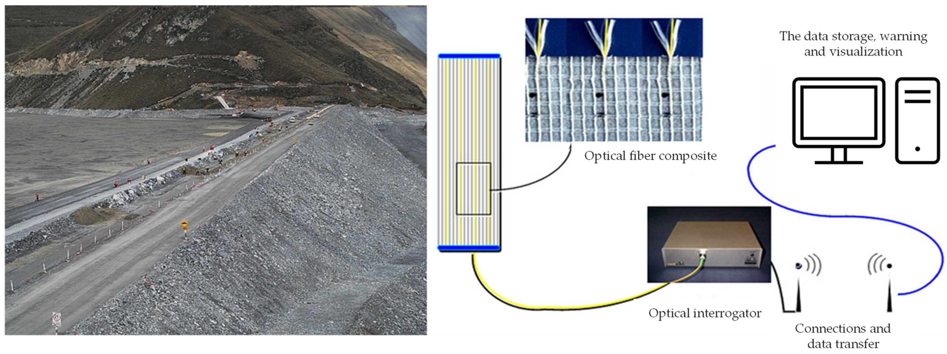
  49. Dijcker, R.; Van Der Wijk, M.; Artieres, O.; Dortland, G.; Lostumbo, J. Geotextile Enabled Smart Monitoring Solutions for Safe and Effective Management of Tailings and Waste Sites. In Proceedings of the 15th International Conference on Tailings and Mine Waste, Vancouver, BC, Canada, 6–9 November 2011. [Google Scholar]
  50. Strachan, C.; Caldwel, J. New Directions in Tailings Management. In Proceedings of the 14th International Conference on Tailings and Mine Waste, Vail, CO, USA, 17–20 October 2010. [Google Scholar]
  51. Brixel, B.; Caldwell, J. Thirty Years of Tailings Seepage History from Tailings & Mine Waste. Available online: https://open.library.ubc.ca/cIRcle/collections/59368/items/1.0107754 (accessed on 21 December 2022).
  52. Klohn, E. Seepage Control for Tailings Dams. 1979. Available online: https://www.imwa.info/docs/imds_1979/IMDS1979_Klohn_671.pdf (accessed on 23 December 2022).
  53. Schwank, S. Cut-off systems for dikes and tailings dams in mining. In Proceedings of the 17th African Regional Conference on Soil Mechanics and Geotechnical Engineering, Cape Town, South Africa, 7–9 October 2019. [Google Scholar]
  54. Yang, J.; Hu, J.; Wu, Y.; Zhang, B. Numerical Simulation of Seepage and Stability of Tailing Dams: A Case Study in Ledong, China. Sustainability 2022, 14, 12393. [Google Scholar] [CrossRef]
Figure 1. Schematic view of process water (water in contact with mine tailings) management and seepage control in TSF.
Water 15 00196 g001
Figure 2. Typical process water management and seepage control in a TSF.
Water 15 00196 g002
Figure 3. Typical sulphide gold ore flowsheet process—gold mine tailings management [4].
Water 15 00196 g003
Figure 4. Gold mine tailings management—fully lined TSF—Tambomayo TSF, Peru [7].
Water 15 00196 g004
Figure 5. Typical sulphide copper ore flowsheet process—copper mine tailings management [4].
Water 15 00196 g005
Figure 6. Copper mine tailings management–partially lined TSF—Los Quillayes TSF, Chile.
Water 15 00196 g006
Figure 7. Example of cutoff trench and grout curtain system construction in a TSF.
Water 15 00196 g007
Figure 8. Example of plastic concrete slurry wall–grout curtain system in TSF dam.
Water 15 00196 g008
Figure 9. Example of detail of plastic concrete slurry wall with cement–bentonite grout curtain in TSF.
Water 15 00196 g009
Figure 10. Examples of a geomembrane liner, cutoff trench, and grout curtain system in a TSF.
Water 15 00196 g010
Figure 11. Schematic example of seepage collection system in TSF.
Water 15 00196 g011
Figure 12. Seepage collection sumps in a TSF-Chile.
Water 15 00196 g012
Figure 13. Geomembrane installation—typical construction activities, 2H:1V dam slope–Peru.
Water 15 00196 g013
Figure 14. Geomembrane seams—typical details.
Water 15 00196 g014
Figure 15. Schematic view of a starter dam with typical geosynthetics installation.
Water 15 00196 g015
Figure 16. Starter dam upstream face geotextile–geomembrane liner installation first stage finished—TSF Starter Dam, Chile [42,43].
Water 15 00196 g016
Figure 17. Starter dam upstream face geotextile–geomembrane liner installation second stage finished—TSF Starter Dam, Chile [42,43].
Water 15 00196 g017
Figure 18. Schematic view of cycloned tailings sand dam construction.
Water 15 00196 g018
Figure 19. Panoramic view of TSF starter dam with geomembrane liner and mine tailings hydrocyclone station—TSF, Chile.
Water 15 00196 g019
Figure 20. Cycloned tailings sand dam upstream face waterproofing—TSF, Chile [44].
Water 15 00196 g020
Figure 21. Cycloned tailings sand dam upstream face waterproofing construction detail.
Water 15 00196 g021
Figure 22. Cycloned tailings sand dam upstream face waterproofing construction process—TSF, Chile.
Water 15 00196 g022
Figure 23. Panoramic view—mine waste rock dam upstream face waterproofing construction detail— TSF, Peru.
Water 15 00196 g023
Figure 24. Front view—mine waste rock dam upstream face waterproofing construction detail—TSF, Peru.
Water 15 00196 g024
Figure 25. Mine waste rock (rockfill) dam upstream face waterproofing construction detail.
Water 15 00196 g025
Figure 26. Mine waste rock dam upstream face waterproofing with bituminous geomembrane—TSF, Peru.
Water 15 00196 g026
Figure 27. Mine waste rock dam upstream face waterproofing with bituminous geomembrane—construction details.
Water 15 00196 g027
Figure 28. Example of smart geosynthetic with fiber optics technology.
Water 15 00196 g028
Figure 29. Example of use of geosynthetic liner in the zone of a TSF in contact with rock–TSF Peru.
Water 15 00196 g029
Table 1. Characteristics of tailings storage facilities with the highest dams in the world—mining projects in Chile and Peru [3].
Tailings Storage Facility NameMine NameCountryTailings Production Rate (mtpd)Dam Construction MaterialProjected Dam Height (m)
Los LeonesAndinaChileClosure PhaseBorrow material160
Pampa PabellonCollahuasiChile170,000Mine waste rock90
TalabreChuquicamataChile200,000Mine waste rock50
Los QuillayesLos PelambresChileClosure PhaseCycloned tailings sand198
El MauroLos PelambresChile205,000Cycloned tailings sand237
OvejeriaAndinaChile75,000Cycloned tailings sand130
Las TortolasLos BroncesChile125,000Cycloned tailings sand150
Pampa AustralSalvadorChile35,000Borrow material36
CarenEl TenienteChile180,000Borrow material70
Quebrada BlancaQuebrada Blanca Phase IIChile140,000Cycloned tailings sand310
La BreaCaseronesChile50,000Borrow material248
CandelariaCandelariaChileClosure PhaseMine waste rock160
Los DiquesCandelariaChile75,000Mine waste rock156
AndacolloCarmen de AndacolloChile55,000Mine waste rock150
Quebrada LingaCerro VerdePeru240,000Cycloned tailings sand305
Quebrada EnlozadaCerro VerdePeruClosure PhaseCycloned tailings sand200
Quebrada AyashAntaminaPeru145,000Mine waste rock265
Las BambasLas BambasPeru140,000Mine waste rock220
ConstanciaConstanciaPeru90,000Mine waste rock170
Quebrada HondaCuajone and ToquepalaPeru150,000Cycloned tailings sand180
Quebrada CortaderaQuellavecoPeru127,500Cycloned tailings sand300
QuebradaTunshurucoToromochoPeru140,000Mine waste rock245
Table 2. Nonwoven, needle-punched geotextile properties [29,30,31,32,33,34,35,36,37].
Properties of MaterialTest
Method
Unit of MeasureRequired ValueRequired Value
Weight Per Area UnitASTM D5261g/m2 (oz/yd2)≥335 (10)≥180 (6)
Apparent Opening Size, Sieve No.ASTM D4751mm≤0.15≤0.21
Grab Tensile StrengthASTM D4632N≥1110≥600
Grab ElongationASTM D4632%≥50≥50
Puncture StrengthASTM D4833N≥665≥350
Trapezoidal TearASTM D4533N≥445≥240
PermittivityASTM D44911/s≤1.2≤1.4
Flow RateASTM D4491l/min/m2≤3100≤4500
UV Resistance (after 500 h)ASTM D4355%≥70≥70
Table 3. HDPE smooth-textured, black-colored geomembrane properties [29,30,31,32,33,34,35,36,37].
Properties of MaterialTest MethodUnit of MeasureRequired Value
ThicknessASTM D5199mm (mil)≥1.5 (60)
DensityASTM D1505g/cm3≥0.94
Strength at YieldASTM D6693N/mm≥22
Strength at BreakASTM D6693N/mm≥40
Elongation at YieldASTM D6693%≥12
Elongation at BreakASTM D6693%≥700
Tear ResistanceASTM D1004N≥186
Puncture-ResistanceASTM D4833N≥480
Oxidative Induction TimeASTM D3895Min≥100
Carbon Black ContentASTM D1603%2.0–3.0
Table 4. Geomembrane liner design matrix [38].
Foundation Conditions (α)Liner
Bedding Soil (β)
Overliner
Material
(γ)
Effective Normal Stress (MPa) (σ)
σ < 0.50.5 < σ < 1.2σ > 1.2
Firm or High StiffnessCoarse grainedCoarse grained Fine grained2.0 mm HDPE
1.5 mm HDPE
2.0 mm HDPE
2.0 mm HDPE
2.5 mm HDPE
2.5 mm HDPE
Fine grainedCoarse grained Fine grained1.5 mm HDPE
1.0 mm HDPE
1.5 mm HDPE
1.5 mm HDPE
2.0 mm HDPE
2.0 mm HDPE
Soft or Low StiffnessCoarse grainedCoarse grained Fine grained2.0 mm LLDPE
1.5 mm LLDPE
2.0 mm LLDPE
2.0 mm LLDPE
2.5 mm LLDPE
2.5 mm LLDPE
Fine grainedCoarse grained Fine grained2.0 mm LLDPE
1.5 mm LLDPE
2.0 mm LLDPE
2.0 mm LLDPE
2.5 mm LLDPE
2.5 mm LLDPE
(α): Foundation condition’s description is a relative measure of stiffness. The foundation conditions need to be investigated and tested to determine compatibility with the geomembrane. (β): Liner bedding soil refers to the soil in direct contact with the underside of the geomembrane. To assess compatibility with the geomembrane, testing and design calculations are required. (γ): Overliner refers to the material placed directly onto the geomembrane. To assess compatibility with geomembrane, testing and design calculations are required. (σ): Effective normal stress is the maximum stress onto the geomembrane due to the tailings and other externally applied loads.
Table 5. Calculated unitized leakage rates, 1 L per hectare per day (lphd), due to permeation of water through an HDPE geomembrane (1 mm) [39,40].
Water Depth on Top of the Geomembrane, hw
0 m
(0 ft)
0.003 m
(0.01 ft)
0.03 m
(0.1 ft)
0.3 m
(1 ft)
3 m
(10 ft)
>10 m
(>30 ft)
Coefficient of Migration, mg (m2/s)09 × 10−209 × 10−189 × 10−169 × 10−143 × 10−13
Unitized leakage rate, qg------
(m/s)09 × 10−179 × 10−159 × 10−139 × 10−113 × 10−10
(lphd)08 × 10−50.0080.880260
(gpad)08 × 10−60.00080.08828
Values of leakage rate in liters per hectare per day (gallons per acre per day).
Table 6. Calculated leakage rates due to pinholes and holes in a geomembrane (1 mm) [39,40].
Water Depth on Top of the Geomembrane, hw
Defect
Diameter
0.003 m
(0.01 ft)
0.03 m
(0.1 ft)
0.3 m
(1 ft)
3 m
(10 ft)
30 m
(100 ft)
Pinholes1 mm0.0060.060.6660
(0.004 in)(0.0015)(0.015)(0.15)(1.5)(15)
0.3 mm0.55505005000
(0.012 in)(0.1)(1)(13)(130)(1300)
Holes2 mm4013040013004000
(0.08 in)(10)(30)(100)(300)(1000)
11.3 mm1300400013,00040,000130,000
0.445 in)(300)(1000)(3000)(10,000)(30,000)
Values of leakage rate in liters/day (gallons/day).
Disclaimer/Publisher’s Note: The statements, opinions and data contained in all publications are solely those of the individual author(s) and contributor(s) and not of MDPI and/or the editor(s). MDPI and/or the editor(s) disclaim responsibility for any injury to people or property resulting from any ideas, methods, instructions or products referred to in the content.

