1. Introduction
Due to the increasing demand for water resources in urban settings of the Alberta Plains region, there is an urgent need to quantify the resource in order to manage it sustainably. Several studies have established the glacial melt contribution to watersheds and to surface run-off near the CRM and directed to the Alberta Plains [
1,
2]. In addition, ref [
3] showed that even if the ice-melting contribution to streamflow is not as important as the snowpack melt contribution, the glacier acts as a retention area for the snowpack. Nevertheless, only a few studies have focused on the glaciers’ contribution to groundwater flow in the region, particularly focused on a regional area such as the Alberta Plains [
1,
2,
4,
5]. Using isotopes and natural tracers, a recent study detected the driving forces and mechanisms of recharge in mountains, south of the border in the Columbia River Basalt Province [
6].
Deep groundwater flow is poorly understood due to the inaccessibility of the terrain and thus, the lack of data. Hydrogeological models of deep groundwater flow have been built for other mountainous regions of the world, often linking the flow to topographic elevation but also identifying deeper flow systems directed towards the plains and foothills [
7,
8]. Still, glaciers are not present in these study areas. The effect of the overpressure imposed by the glaciers in mountainous region on regional flow towards sedimentary plains has not been well documented, and very few studies exist on the effects of postglacial rebound [
9].
In western Canada, as in most cold regions, receding glaciers and ice fields are affecting surface and groundwater resources downstream and more generally the dynamics of the water cycle. The most relevant and recent research on the effects of the snowpack melt on recharge on the plains in the proximity of mountain ranges are Medici et al., [
10] and Behrens et al., [
6].
It is widely accepted that aquifer recharge near or within mountainous regions originates from infiltration of liquid or solid precipitation, or indirectly from the melting of glaciers [
11,
12]. Glaciers located on the Canadian Rocky Mountains (CRM) are considered as the water source of the geology-delimited aquifers in the Canadian Plains; thus, it is speculated that increasing melt runoff from those glaciers would affect their recharge dynamics. Two recent studies explored the groundwater storage changes in the prairies of Alberta, East and closer to the CRM. Huang et al. [
13] decomposed the GRACE signal to infer an increasing groundwater storage trend gradient, higher in Eastern Alberta than close to the CRM, suggesting that glacier mass loss is not the main driver of this observed increase. Bhanja et al. [
14] studied the relations between in situ groundwater storage change observations in Alberta, with precipitation and GRACE-derived groundwater storage changes. They observed poor degrees of correlation for most watersheds connected to the CRM, suggesting for instance, that recharge processes other than direct vertical infiltration from precipitation occur. Thus, there remains debate on whether recharge is driven primarily by focused or diffused near-surface infiltration, surficial horizontal groundwater exchanges within shallow groundwater systems, or by basal groundwater flux through deep-seated basin fractures. While glacial melt is generally well quantified at the global scale, little is known about the associated changes on downstream flow systems, infiltration into the ground, and their potential impacts on surface water and groundwater-dependent human communities settled downstream [
2].
This paper aims to evaluate the possible contribution of CRM glaciers to the groundwater resource of the Alberta Plains, with 2D hydrogeological finite-element analyses of regional deep groundwater flow. The work follows and complements a recent study by Castellazzi et al. [
2]. These authors evaluated glacier melt and potential impacts on water resources in the Canadian Rocky Mountains (CRM) using GRACE and glacial mass balance modelling.
This work provides a review and integrates the available data for the study area prior to the three-dimensional geological modelling of the area. Thereafter, three 2D hydrogeological models of cross-sections extended from the CRM to the Alberta Plains are built to verify the extent of the flow from the glaciers and, if the flow reaches the Plains, quantify the contribution of the glaciers to the groundwater flow in the Plains. Groundwater flow systems are identified and used in order to discretize the models in sub-flow areas. From the groundwater flow system division, a sensitivity analysis on multiple parameters of the models is executed to also identify the major influence factors on this flow.
2. Study Area and Climate
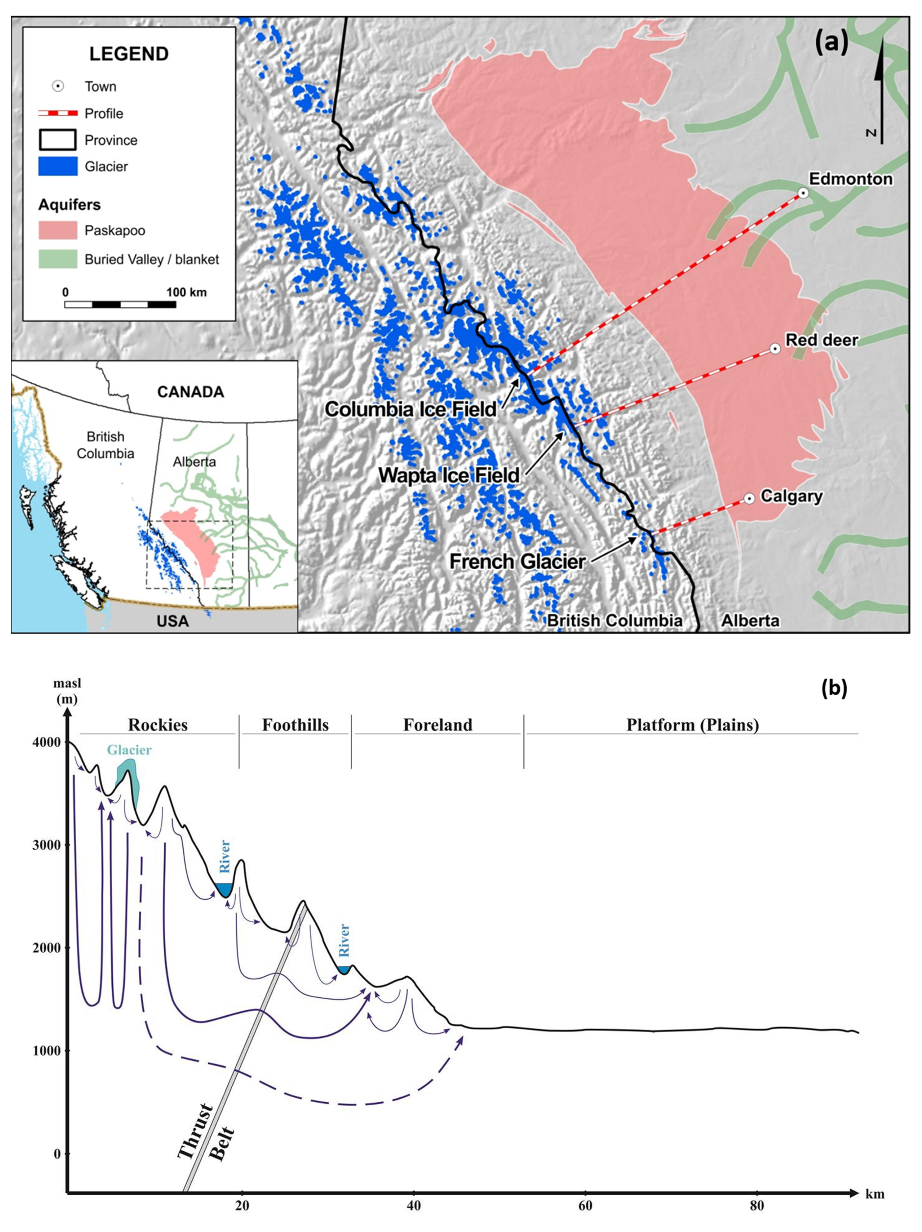
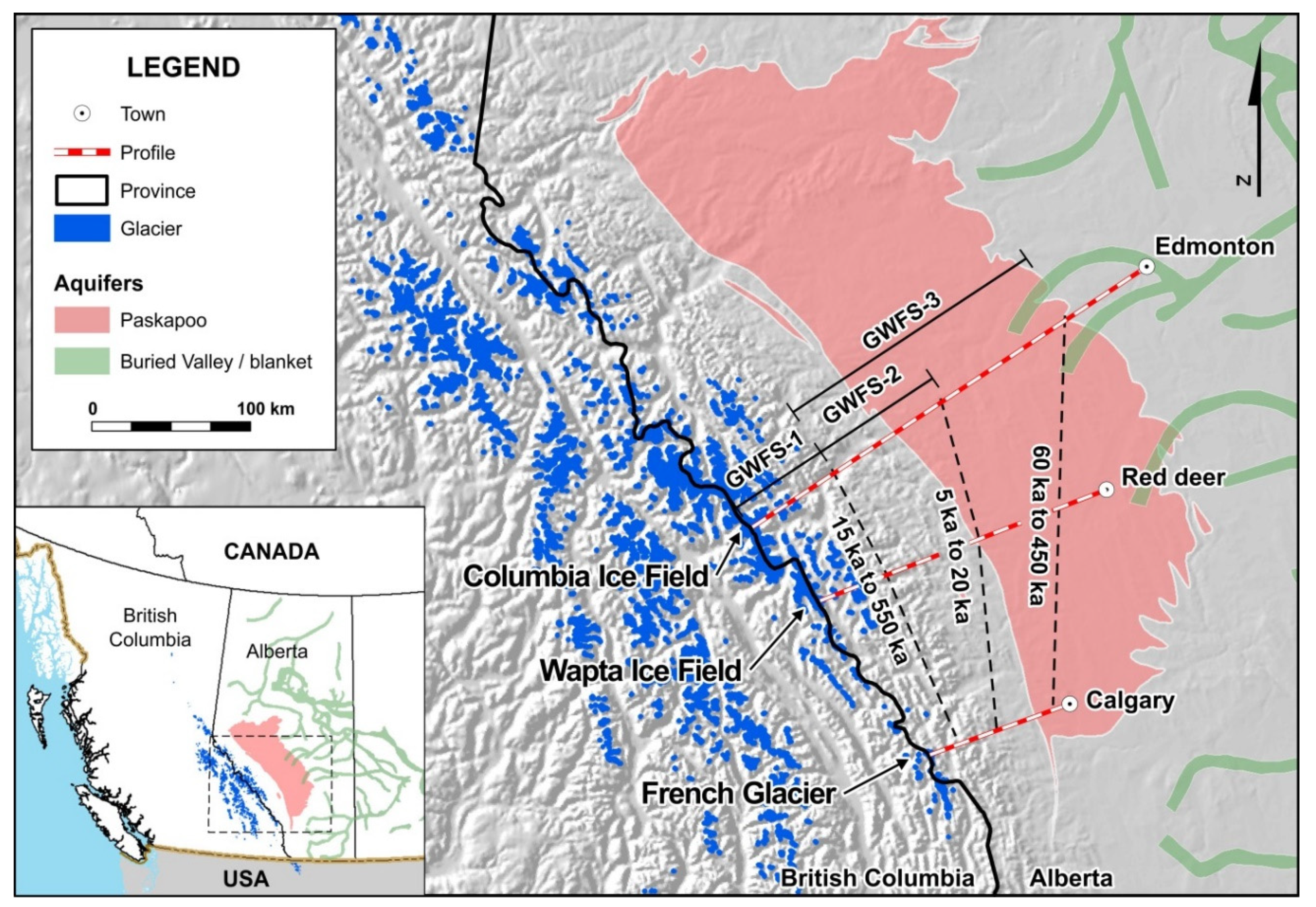
The study area is located in the central and southern parts of Alberta, Canada (
Figure 1a). Since the objective of this study is to quantify the contribution of the glaciers to groundwater in urban catchments of Alberta, the domain of interest is limited by the CRM ridge to the West and by the major cities of Alberta to the East. The northern extent is set by the city of Edmonton and the southern extent is set by the city of Calgary.
The land is divided into four topographical and geomorphological regions and sub-regions which are, from West to East, the Main Ranges and Front Ranges (Rockies), the Foothills, the Foreland, and the Sedimentary platform of the Canadian Plains, as shown in the conceptual generalized schematic cross section of
Figure 1b (in this study we present cross sections and 2D models results with vertical exaggeration to emphasize groundwater flow features). According to Graf [
15] and Töth [
16], the presence of those geomorphological features may have regional effects on major basinal flow patterns defined as “cordillera-cum-foreland”. These types of basins comprise one side of cordillera-type high mountain ranges, their foothills, and the adjacent rolling plains, i.e., the Foreland (
Figure 1b). Usually, the mountains are tectonically detached from the foothills by a belt of low angle thrust faults [
16]. In the Western Canada Sedimentary Basin (WCSB, situated mainly in Alberta), convective geothermal-energy transport is generally driven by recharge in the foothills and Rocky Mountains, flowing down into the basin and up-dipping to the northeast and east [
15], which is a manifestation of the presence of groundwater storage in the mountains.
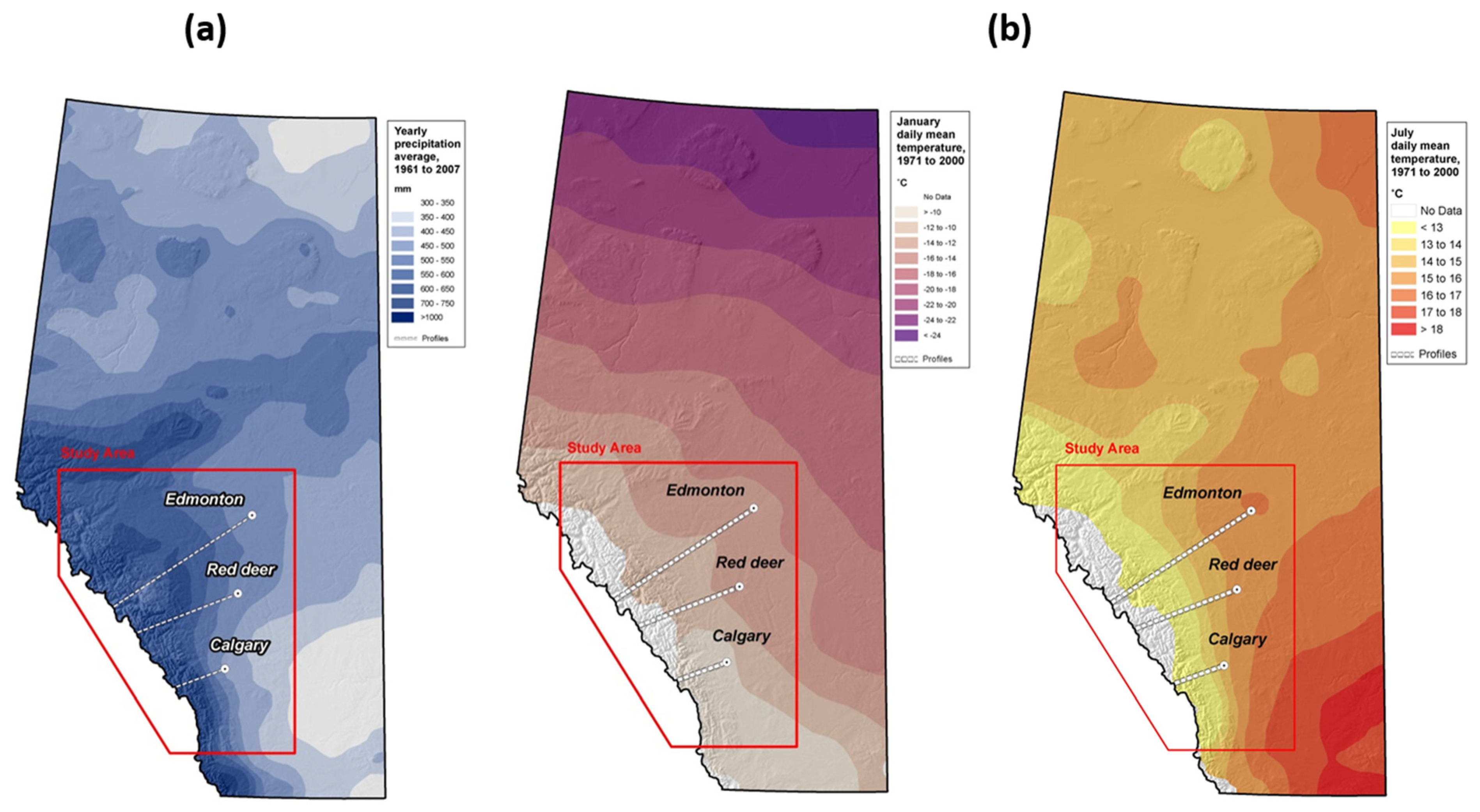
There is a wide range of varying and contrasting environmental factors in the Rocky Mountains and lower Plains. Precipitation ranges from 300 mm per year in the lower valleys to 1500 mm per year locally on the highest peaks. Average January temperatures can range from −25 °C in in higher altitudes, to 0 °C in Calgary.
Figure 2 shows mean annual precipitation and temperature distributions in the Province of Alberta. According to Clarke et al. [
17], the current warming climate is expected to completely melt the remaining glaciers, located in the Rockies, by 2120.
3. Geological Setting
The geology of Alberta can be described from the Western Canada Sedimentary Basin divided into two sedimentation zones; one from the Paleozoic to the Jurassic and another one from the Jurassic to Paleocene [
20]. The Jurassic to Paleocene zone was deposited in an active tectonic orogenic environment, during the development of the Canadian Cordillera. In general, the three-dimensional geological model (see numerical models below) was built using sequence stratigraphy and structural geology. Cross sections were extracted from the 3D geological model and compared with the characterization of aquifers/aquitards from other authors, for reliability (e.g., Grasby et al. [
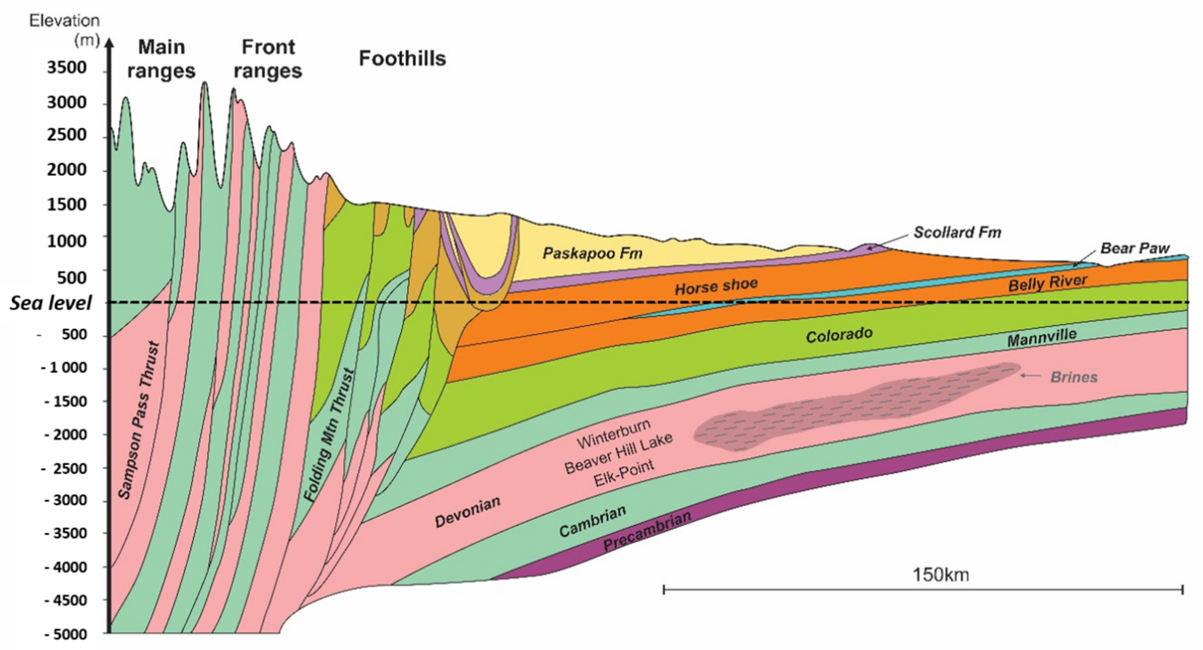
21]. The conceptual model of the geological settings is presented in
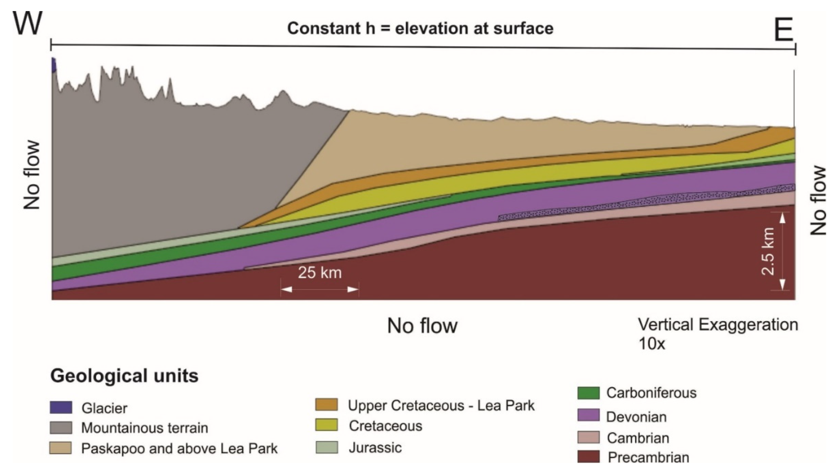
Figure 3 with a west-east cross section.
Hydrostratigraphy
The domain of interest is described in terms of lithological units forming the rock mass, neglecting the unconsolidated sediments. From the surface, the first unit is the Paskapoo Tertiary unit, one of the most important aquifers supplying groundwater for the Province of Alberta. This unit lies on the Edmonton Group succession, counting an alternation of aquifers and aquitards and joining the Upper Cretaceous period and the Tertiary. This group lies on the Lea Park aquitard, a marine shale formation from the Upper Cretaceous [
23].
The Tertiary/Top Cretaceous—Paskapoo and above Lea Park is composed of sandstone-dominated rocks with numerous sand channels encased in mudstones. The Paskapoo Formation is an extensive Tertiary fluvial mudstone and sandstone complex covering 65,000 km
2 [
22]. It forms the westernmost and most extensive erosional remnants of Tertiary deposits equivalent to those in Saskatchewan and Manitoba. The Tertiary/Top Cretaceous, which includes the Paskapoo Fm, is an extremely heterogenous sedimentary layer, mostly composed of clastic rocks. We conceptualized the Upper Cretaceous/Lea Park as clastic aquifers, also dominated by sandstone with intercalation of mudstones. Carbonate rocks are present in scattered places along the Foothills or in deep layers such as the Colorado group and the Devonian; metamorphic and igneous rocks are mostly present in the mountainous terrain.
The Upper Cretaceous—Lea Park include the Edmonton group composed of the Scollard, Horseshoe and Bearpaw clastic formations. The Cretaceous unit includes the Mannville and Colorado groups and the Belly River formation all three considered integrated in the Cretaceous unit as clastic aquifers. The Jurassic unit is the last geological formation in the second sedimentation zone of the basin and it is included as an aquifer in the models. The Carboniferous is included in the sequence representing the first sedimentation zone in the basin and it is included as an aquifer with a rather poor permeability. The Devonian unit contains brines and it is included as an aquitard in the models. The Cambrian and Precambrian units are included as aquitards in the models.
4. Hydrogeology
The principal hydrogeological features of the Plains in the Alberta region are described in this section, including the multi-layered aquifer-aquitards system, groundwater flow systems and principal parameters.
4.1. Aquifers
The Plains region is characterized by a regional-wide basin of low relief sub-horizontal, multi-aged sedimentary rocks. Carbonate and ancient fluvial rocks set mainly in mudstone units. Overlying thick glacial deposits may be extensive and contain buried valleys. Incised postglacial valleys provide local relief. Fresh, potable groundwater is abundant in shallow fractured aquifers, thick muddy glacial sediment host buried valleys, as well as in inter-till aquifers. Groundwater availability with depth is limited due to overlying aquitards, a dry climate with restricted modern recharge, and in some areas, high concentrations of dissolved solids. Most groundwater supplies draw on shallow aquifers which are recharged locally. Deeper confined aquifers receive very little recharge, perhaps only sub-horizontal, time-delayed fluxes from the West.
The flow of groundwater through the bedrock aquifers located in the study area occurs mainly through fractured media, essentially driven by topography at the regional scale, mostly with west-east and southwest-northeast directions. Local-scale groundwater flows also exist but are mostly heterogeneous flows driven by localized conditions such as pumping, presence of multilayered systems, geothermal gradients, or the high concentration of dissolved solids [
23]. Given the regional scale of our models, we adopted the Equivalent Porous Media (EPM) approach, that is, we did not simulate fracture flow. The flow of groundwater is through an EPM, the depth of flow is controlled by the hydraulic conductivity and topography of the discretized layers in our models.
4.2. Hydraulic Conductivity
Table 1 shows the expected average hydraulic conductivities found in the study area based on a literature review. The Paskapoo and Upper Cretaceous units above Lea Park are considered to have a hydraulic conductivity of 1 × 10⁻⁵ m/s, based upon the value identified by Barker et al. [
23] giving more importance to the permeable Paskapoo aquifer for the entire strata. The other units of the Tertiary and Upper Cretaceous hydraulic conductivities vary from 1 × 10⁻⁵ to 1 × 10⁻⁹ m/s [
23]. The Lea Park unit’s hydraulic conductivity is considered smaller than the unit above; a value of 1 × 10⁻⁶ m/s is expected for this unit. As for the mountainous terrain, an equivalent porous media is considered to represent this area. A hydraulic conductivity of 1 × 10
−7 m/s is estimated, based on the work of Gleeson and Manning [
8]. Slightly North of the domain extent, the Upper Devonian permeability has been characterized with values ranging from 2.5 × 10
−17 m
2 to 3.9 × 10
−11 m
2 (equivalent to hydraulic conductivities of 2.3 × 10
−10 to 3.6 × 10⁻
4 m/s [
24]). The same study determined the permeability values for the Jurassic aquifers, extending from 10
−17 m
2 to 2.09 × 10
−12 m
2 (equivalent to hydraulic conductivities of 1.1 × 10
−10 to 2.3 × 10⁻⁵ m/s). No data was available for the Precambrian hydraulic conductivity, so the value for this lithology is set to 1 × 10
−11 m/s, based upon the works of Jayne et al. [
7]. The other units of the Tertiary and Upper Cretaceous hydraulic conductivities vary from 1 × 10⁻⁵ to 1 × 10⁻⁹ m/s [
23]. The hydraulic conductivity set for the Cretaceous is slightly smaller (4.9 × 10⁻⁸ m/s) than the Lea Park conductivity, since it is also an aquitard (Colorado group), combined with a lower aquifer (Mannville group). The Jurassic aquitard is set again with a slightly higher value (1 × 10⁻⁷ m/s), because of the Nikanassin formation [
25] which is part of the Lower Mannville aquifer, in the upper part of this Period. The lower lithologies are set with gradually decreasing hydraulic conductivities with increasing depth. The lowest hydraulic conductivity is set for the Precambrian strata with a value of 1 × 10⁻
11 m/s. A default value of 1 × 10
−4 m
−1 is used as specific storage, since the real capacity of each layer has not been established in previous studies
4.3. Salinity
The salinity of formation waters varies widely from one hydrogeological unit to another. For the Lea Park Unit and above, the salinity has been established in a range of 1600 to 10,000 mg/L. Water density in the Alberta Basin has been established by Michael and Bachu [
25]; they stated that the water density varies from 1003 kg/m
3 to 1040 kg/m
3 for the Upper Cretaceous (Brazeau-Belly aquifer) and the Lower Cretaceous (Mannville aquifer), respectively. There is presence of brines at depths in the Devonian geological unit. The salinity concentration of the Devonian brines reaches up to 213,000 kg/m
3 [
26]. These large values are of interest because groundwater quality and groundwater flow may be affected by the brines; this effect is not included in this study. Values of salinity were determined by collecting samples from brine springs discharging from the Devonian carbonates on the Western Canada Sedimentary Basin. As reported by Grasby and Chen [
26], stable isotope data suggested the brine springs originated as Pleistocene meltwater with distinct water chemistry from brines in laterally equivalent units deeper in the basin. Other hydrochemical data was collected from drill-stem tests [
25].
4.4. Conceptual Hydrogeological Model
The deep cross sections from the Rockies to the Plains are based on the current knowledge of the hydrogeological settings of the region [
21,
23]. Most recharge occurs in the eastern, higher altitudes of the Rockies, where precipitation is greater and where the glaciers are located. It is widely believed that the glaciers from eastern Rockies are the geological source of groundwater for the aquifers in the Plains, e.g., providing base flow to numerous rivers [
1,
4,
5].
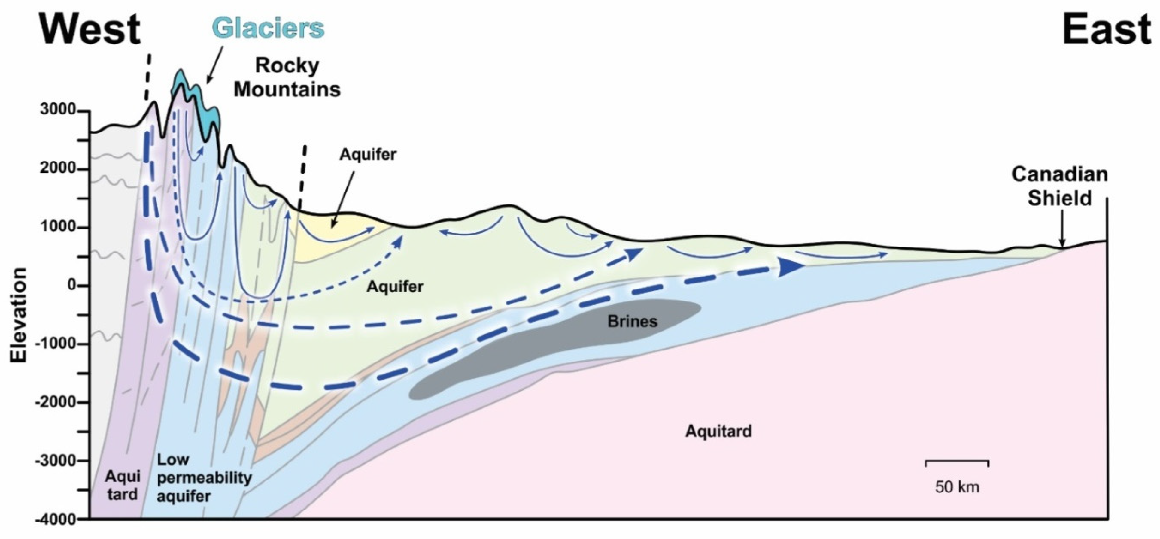
As shown conceptually in
Figure 4, recharge from melting glaciers, flows vertically but stays above the Cambrian formation, generally flowing through the Tertiary, Cretaceous, and Devonian formations. Grasby and Chen [
26] suggest that the Devonian brines eventually manifest themselves as springs at the eastern edge of the Canadian Shield. Ferguson et al. [
27] suggest that brines persist in the Devonian and are not driven out due to gravity. Numerical modelling will assist us in understanding how long it takes for recharge water, in the form of melting glacier water, to flow through the Rockies and geological formations of the Plains.
5. Numerical Methods
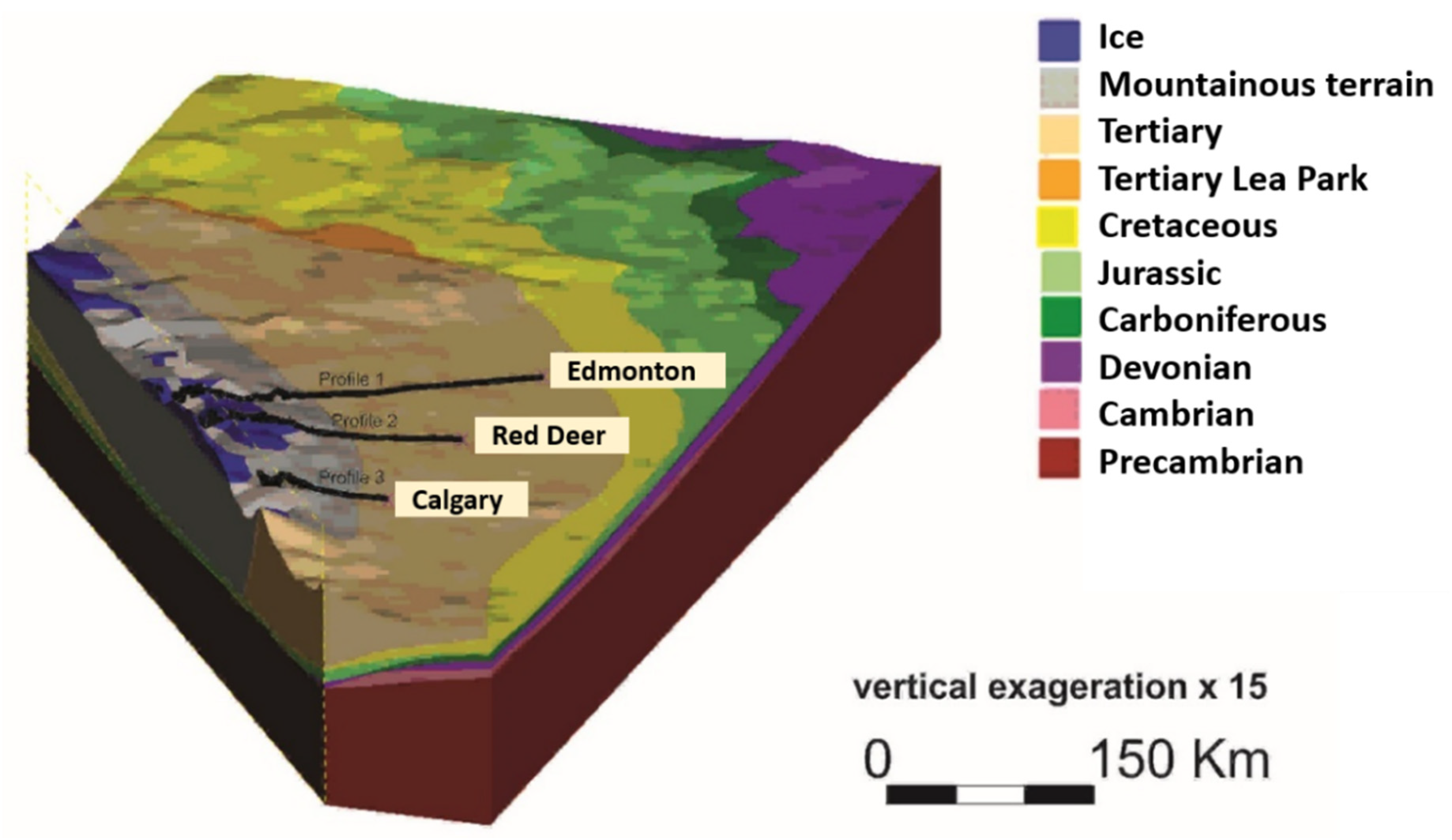
A three-dimensional geological model was built for the study area extending from the Rockies on the West of the study area to the three main cites of Alberta to the East: Edmonton, Red Deer and Calgary. This model includes the major stratigraphic units, divided upon their depositional period. Once the 3D geological model was completed, cross sections were extracted from it, extending from the CRM to each of the three-main cities of Alberta. The geological cross-sections were then used to build the 2D hydrogeological models. This approach was chosen because of the scale of the study area, the depth of the layered systems, and the coupled processes to be modelled. Building and running a full three-dimensional hydrogeological model would have been much more expensive numerically; this is further explained in the results and discussion sections. For simplification purposes, saturated media was assumed over the entire domain and for every model. Given the regional scale of the analysis, Quaternary non-consolidated sediments forming aquifers were neglected, only bedrock layers were considered. Every bedrock layer was considered as an equivalent porous medium, which is a reasonable approximation given the expected groundwater-flow scales.
5.1. Three-Dimensional Geological Model
The 3D geological model was built for this study using LeapFrog
® Hydro 2.0 [
28]. The quaternary sediments and other unconsolidated materials were neglected and bedrock elevation was set as the topography for the geological models. The construction of the stratigraphic geological model made use of available point sets of geological formations imported into the geological modelling software and interpolated from geological solids representing the stratigraphy.
The choice of the geological units was based upon the availability of the isopachs for the study area from Mossop and Shetsen [
20]. It should be noted that all the data were only available from the Foothills to the Alberta sedimentary Plains. Hence, the main Ranges and Front Ranges cannot be divided in strata and are considered as a bulk homogeneous unit called Mountainous Terrain. Since the area of interest is at the regional scale, and due to the restricted available data, the Tertiary and Upper Cretaceous units are considered as one single unit. This consideration gives a simpler model and reduces the errors that could occur from dividing this region in lenses and channels of variable hydraulic conductivity and saturation. Though, it was decided that the Lea Park formation of Upper Cretaceous needed to be separated from the above units. This decision was based upon the hydrogeological character of this formation, which acts as a major aquitard, as opposed to more permeable units of the Tertiary and Upper Cretaceous, i.e., Edmonton Gp [
25].
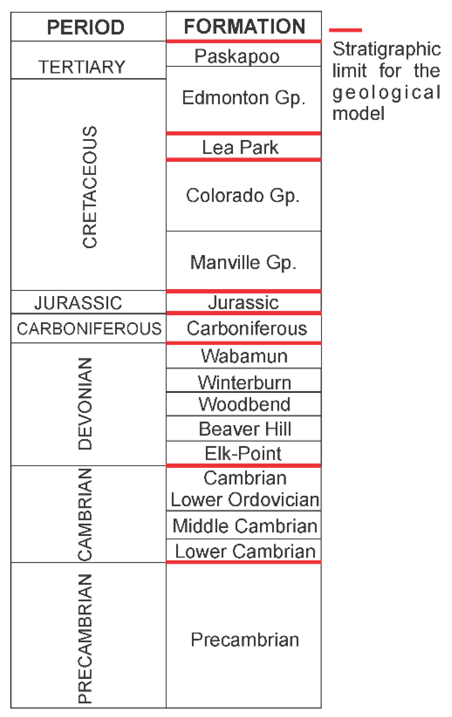
The stratigraphy and divisions of the geological model in the Alberta Sedimentary Plains reference the geological time scale presented in
Figure 5.
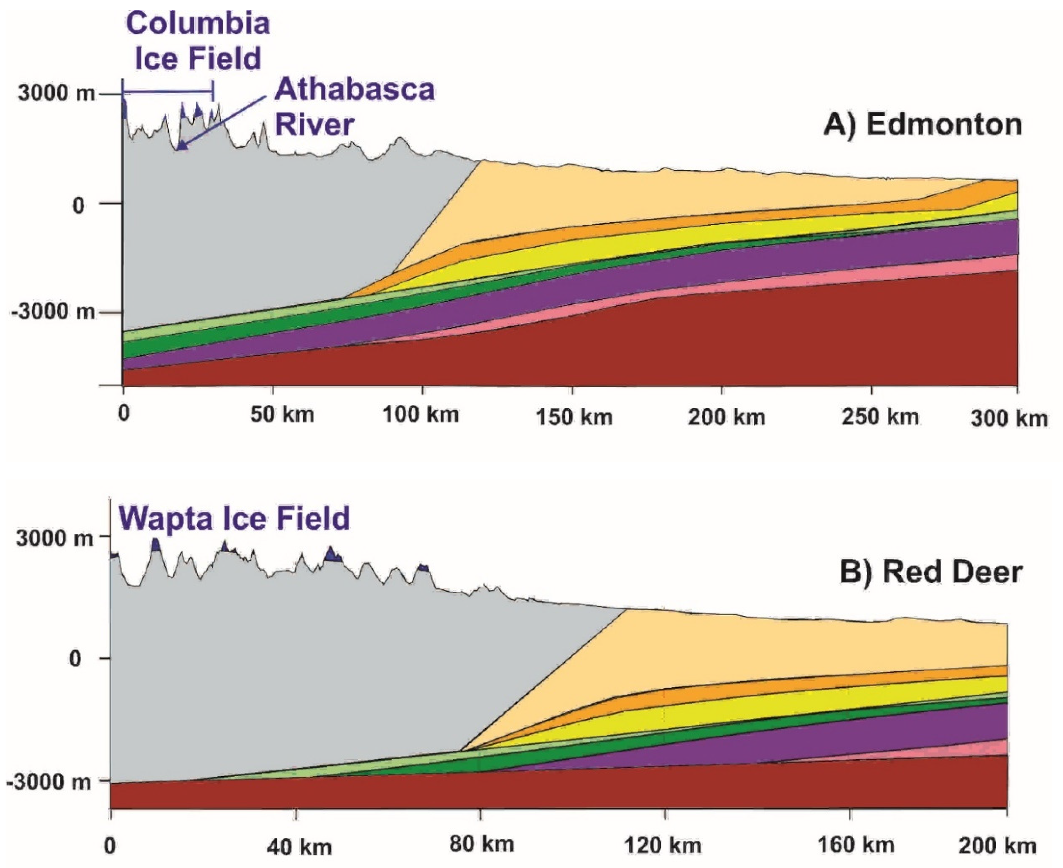
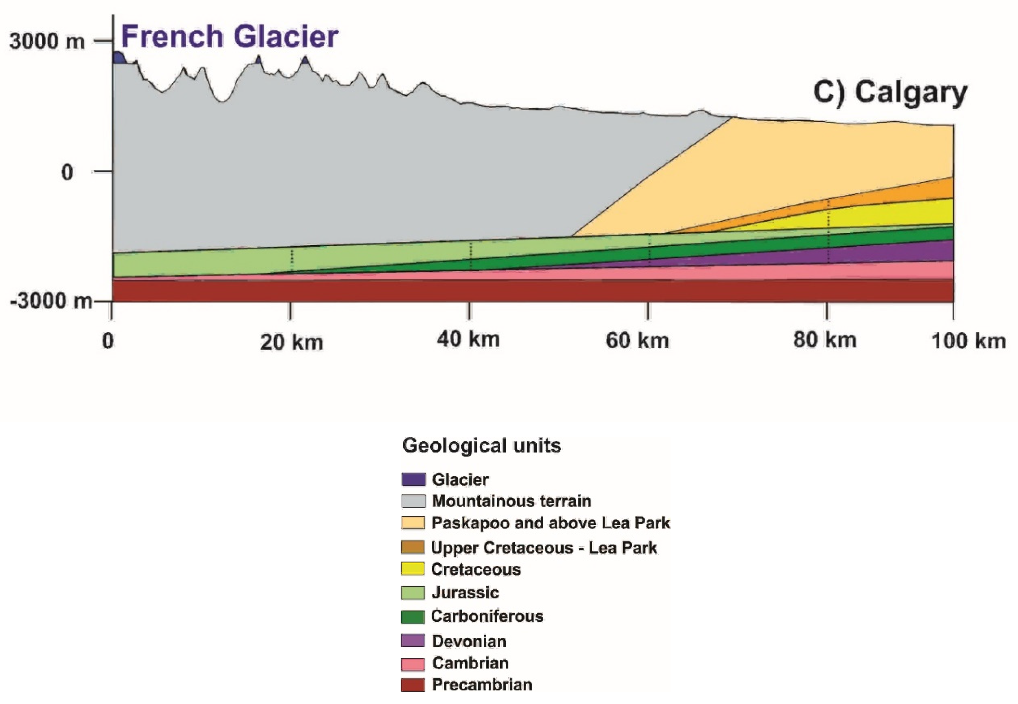
Figure 6 presents the generated 3D geological model with three selected cross sections. The location of the three transects was chosen based on the expected groundwater flow paths to three major Albertan cities (
Figure 1a). The extracted cross sections are presented in
Figure 7. As a general rule, the more the cross sections are located southward, the more the mountainous terrain extends further east and the Paskapoo formation decreases in its extent between the mountains and the major cities.
5.2. Two-Dimentional Groundwater Flow
A series of 2D homogeneous isotropic confined aquifer numerical models were built to simulate steady state and transient fluid flow using FEFLOW [
29]. FEFLOW uses a finite-element approach to solve differential equations for steady-state and transient fluid flow, as well as mass transport in porous media.
6. Simulated Cases
A series of four two-dimensional groundwater-flow cases were simulated as described in
Table 2. The boundary conditions for these cases are described in the following section. Three models with steady-state freshwater flow were run (simulations 1 to 3), one for each 2D cross section: model 1 (Edmonton model), model 2 (Red Deer model), and model 3 (Calgary model). Transient flow for over 800 000 years was run for the Edmonton transect (simulation 4).
Simulations of the Edmonton, Red Deer, and Calgary models helped define groundwater flow directions and magnitudes. Later they also assisted in understanding and defining the time-dependent groundwater flow systems (GWFS) of the study area.
Particle tracking provided flow path directions and associated times. Transient flow simulations cover a period of up to 800,000 years and steady state flow simulations are run for up to 10 million years of transient transport. In the case of transient flow, the simulation time was limited by the historical data going back 800,000 years.
Advective particle tracking may be estimated using values of effective or dynamic porosity, total porosity, or specific yield. Effective porosity represents the proportion of the total porosity involved in groundwater movement; however effective porosity is difficult to measure, values are rare and are generally obtained at the local or site scale. There are no values of effective porosity in the region and at the scale covered by our study. We used a default porosity value of 0.3, which is a reasonable choice for consolidated sediments such as sandstone, siltstone, limestone and basalts [
30]; those are the consolidated bedrock aquifers/aquitards forming the layers in our numerical models.
6.1. Boundary Conditions (BC)
6.1.1. Steady State Flow
Hydraulic heads in the Paskapoo formation can be related to the topographic elevation. Hence, the upper limit of the model, over the Sedimentary Basin, is set equal to the topographic elevation with a Dirichlet boundary condition. Since it is a long-term simulation, through 10,000,000 years, seasonal variability and inter-annual variability [
11] are neglected.
The boundary conditions for the steady state flow of the Edmonton transect (simulation 1) are presented in
Figure 8. For simplicity, the Edmonton transect is used to demonstrate how the boundary conditions were set for the two other transects. The boundary conditions for the two other transects (simulations 2 and 3) are similar to transect 1; hydraulic heads are equal to elevation at the surface; and no flow boundaries on the bottom, eastern and western sides.
The adopted conceptual models in our study, and observations on the regional-scale piezometric distribution, justify the choice of the Dirichlet boundary condition for steady-state flow. The lateral no-flow boundary condition is justified by the horizontal length of the three transects. The western limit is aligned with continental water divide, and the eastern side with the end of the most permeable layer, the Pasakpoo Fm.
6.1.2. Transient Flow, Varying Hydraulic Heads
Only the Edmonton transect was used to simulate transient flow with varying hydraulic head. The transient simulations were run between 800,000 years before present and the year 2100. Variations in hydraulic heads over the past 800,000 years are based on climate data derived from CO
2 records [
31]. Ice height over the study area is represented by a time-variable constant head. Ice elevation is used to infer meters of head using
p =
ρgh where
p is pressure in Pa,
ρ is the density in kg/m
3,
g is the gravitational constant (9.8 m/s
2) and
h is the head from the ice (m).
A direct correlation between CO
2 values in ice cores and temperature has been established by many authors [
31,
32,
33]. There is also a direct correlation between ice volume or ice height and temperature [
33,
34,
35,
36]. Furthermore, estimates of ice elevation over the CRM over the past 800 000 years are based on Marshal et al. [
37] and Peltier et al., [
38], where it is estimated that the last glacial maximum, ice volume and height reached approximately 3000 m in the region.
Historical ice heights, based on empirical data from the study area, dating back more than a few thousand years were not available, thus the Vostok Ice core [
31] was used to infer global temperatures, ice height, and hydraulic head at the Columbia Ice field over 800k years.
Based on the direct relationship observed between CO
2 concentrations and ice volume (e.g., Petit et al. [
33]), ice height in the Canadian Rockies is obtained from CO
2 concentrations in the Vostok Ice core by a simple conversion:
where CO
2 max is the maximum recorded concentration in the Vostok Ice core [
31], CO
2 is the recorded value in the ice core [
31] and the conversion factor (cf) of 23.6 is the value obtained by:
Thus, all ice height values presented here range between 0 m and 3000 m.
Hydraulic head at the surface is set to , where h is the hydraulic head, z is elevation, p is pressure, ρ is the density of ice and g is the gravitational force.
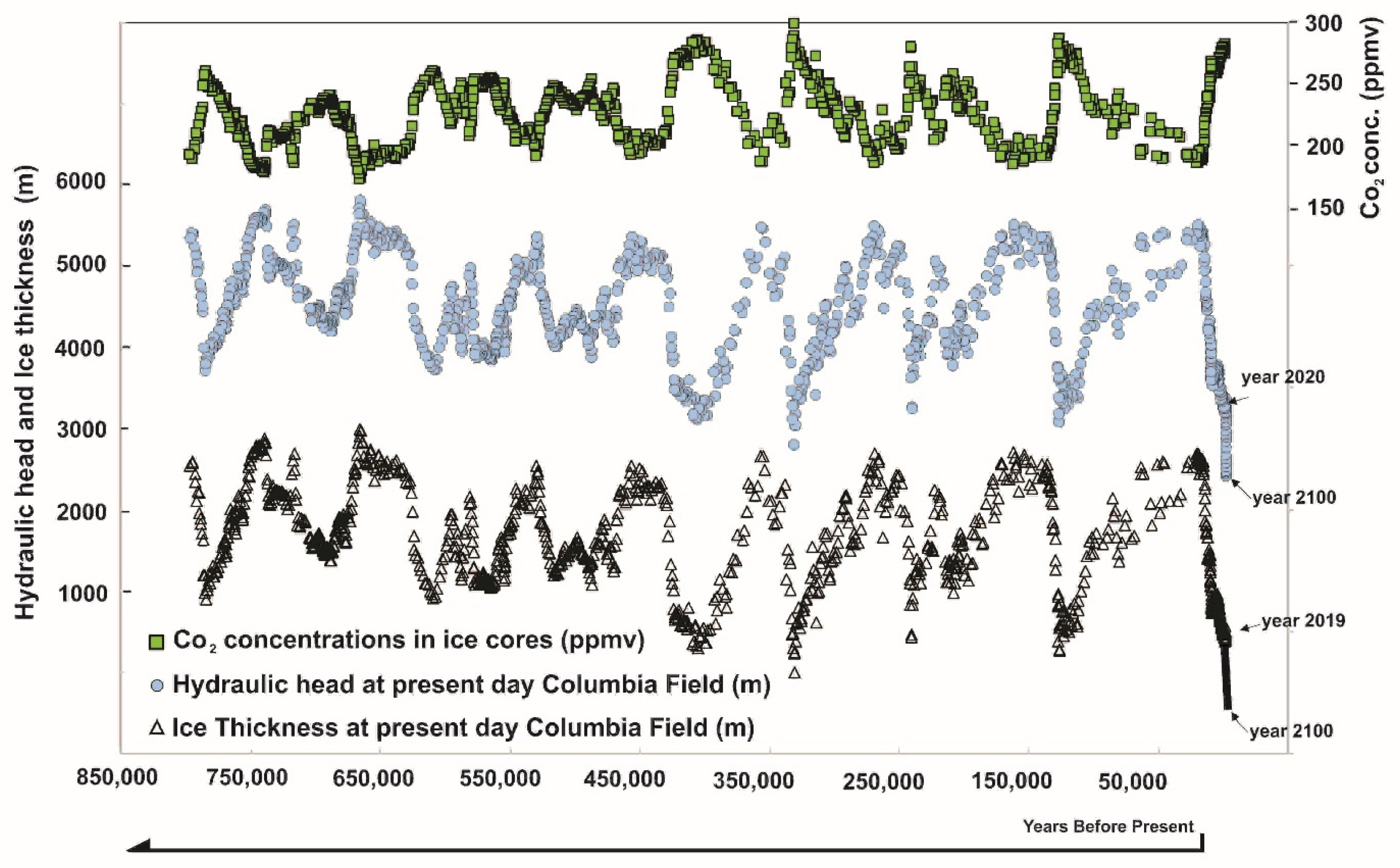
Figure 9 shows the distribution of CO
2 concentrations in ice cores, estimated ice thickness, and estimated hydraulic conductivities over the past 800,000 years and predictions up to the year 2100. The Vostok records [
31] also indicate that the last glacial maximum, approximately 21,000 years ago, was similar in magnitude to other glacial maximums over the past 800,000 years. In addition, the record also indicates that ice volumes of today are at historic lows over the same time period. Therefore, it is assumed that Ice thickness over the CRM, which is currently near zero [
17], has varied between 0 and 3000 m.
Although it is expected that the ice height or hydraulic heads varied by as much as 3000 m over the past 800,000 years, it is assumed that the maximum height values do not apply to the entire domain. There are various models and opinions on ice height over the CRM and the plains over the past ice age [
35,
39,
40]; Person et al. [
41]; Marshal et al. [
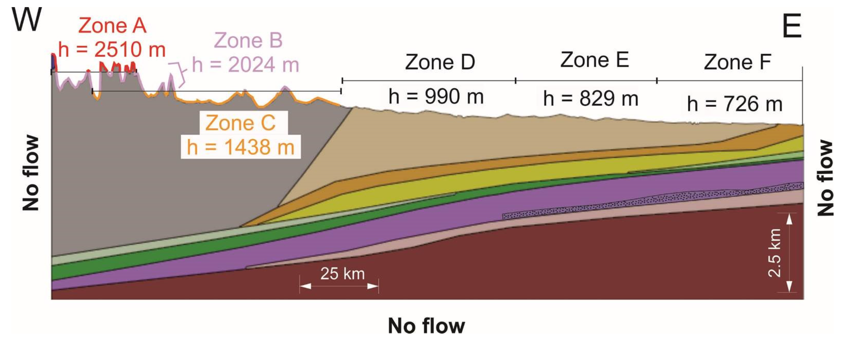
37]. We set the maximum ice height higher in the mountainous regions and lower in the Plains. The lower heights have a maximum of approximately 2000 m. Thus, a proportional variation in ice height was applied to six different zones representing six average elevations, see
Table 3 and
Figure 10.
6.1.3. Initial Conditions, Hydraulic Heads
Hydraulic heads were assigned equal to the topographic elevation. Hydraulic conductivity (K) was assigned as a function of the available literature for each geological formation, and transient simulations involved varying hydraulic heads as a function of glacier height. A first set of satisfactory results was achieved and additional simulations were run to test the sensitivity of the model parameters and other features.
7. Results
7.1. Steady State Flow, Models 1, 2 and 3
Hydraulic head values at the surface were set to ground elevation for the steady-state flow simulations, and for each of the three transect (Edmonton, Red Deer, and Calgary). There was no variation of the hydraulic head with time for this scenario. This scenario assisted in defining the groundwater flow systems presented in
Section 9.
Generally, particles seeded on the surface do not reach the Cambrian and pre-Cambrian formations and, as expected, hydraulic heads follow the topographically-driven flow as described by Tóth [
42].
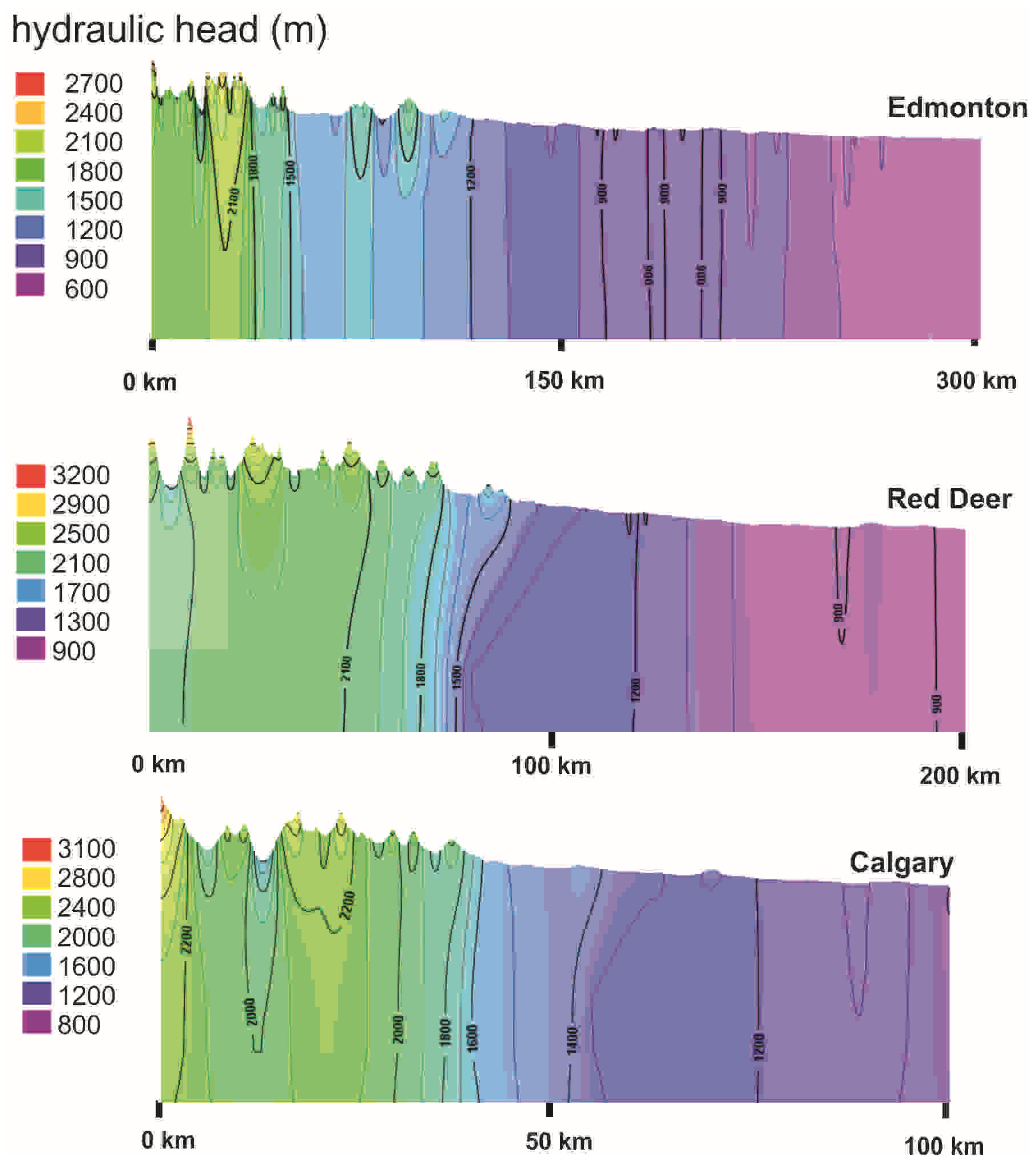
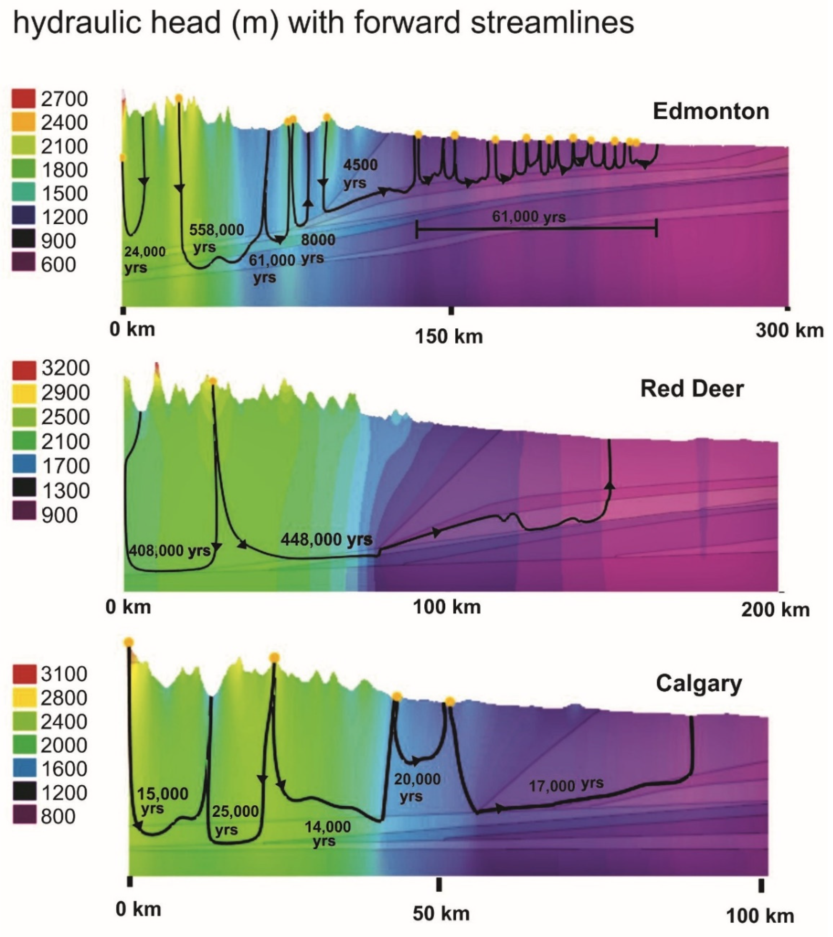
Given the prescribed boundary condition of heads equals to elevation along the top of the models to mimic topographical-driven flow, the results of hydraulic head and flow paths generally indicate that recharge water originating in the peaks flow vertically downward 3.5 to 4 km until they reach low permeability (Carboniferous, Cambrian) formations, at which point the flow is lateral for a brief period and then heads vertically upward. The hydraulic head distribution results for each model are shown in
Figure 11. Isolines across the three transects are also indicated. The Edmonton transect (model 1) is the longest transect and has the largest variation in hydraulic head, ranging between 2700 m in the Rockies to 600 m near Edmonton. The distances for the Red Deer and Calgary transects are shorter with 200 km and 100 km, respectively, however the vertical distances are both larger than the Edmonton transects, each varying 2300 m. As seen by observing
Figure 7 and
Figure 11 for all models, there are changes in flow directions once the flow exits the mountainous terrain. This can be explained by the sudden changes in hydraulic conductivity (see
Table 1) between the Mountainous and Paskapoo or Lea Park formations.
Travel times and paths of particles released from the surface for the 3 models are presented in
Figure 12. Generally, the particles represented in
Figure 12 were chosen because they were the particles that took the longest paths. All other particles along the surface had shorter travel times. No particles are represented in the easternmost section of the three models because the travel times are very short and the paths are very close to the surface. When looking at the groundwater flow in the Plains, one observes a shorter time frame for Model 1 (10s of thousands of years) compared to Models 2 and 3 (hundreds of thousands of years). This is explained by the fact that, for Model 1, flow is mainly occurring in the high hydraulic conductivity Paskapoo formation. Particles originating from the surface in the two other models flow into deeper (Lea Park, Cretaceous, Carboniferous, and Devonian) formations. Particle tracking times in the mountainous region is generally in the hundreds of thousands of years before reaching the Plains.
Groundwater flow rates driven essentially by differences in elevation are shown with ranges from 0.25 to 8 m/y for the three models in deep aquifers (Paskapoo, Lea Park, and Cretaceous). These flow rates indicated with flow paths in
Figure 13 are similar to the typical values in deep aquifers with similar conditions as reported by Garven and Freeze, [
43,
44].
7.2. Transient Flow Model 1
This transient simulation case 4 was run only in model 1 through Edmonton. As described in the transient-flow section of the boundary conditions, the transient flow involved varying hydraulic heads with time to simulate ice thickness over time.
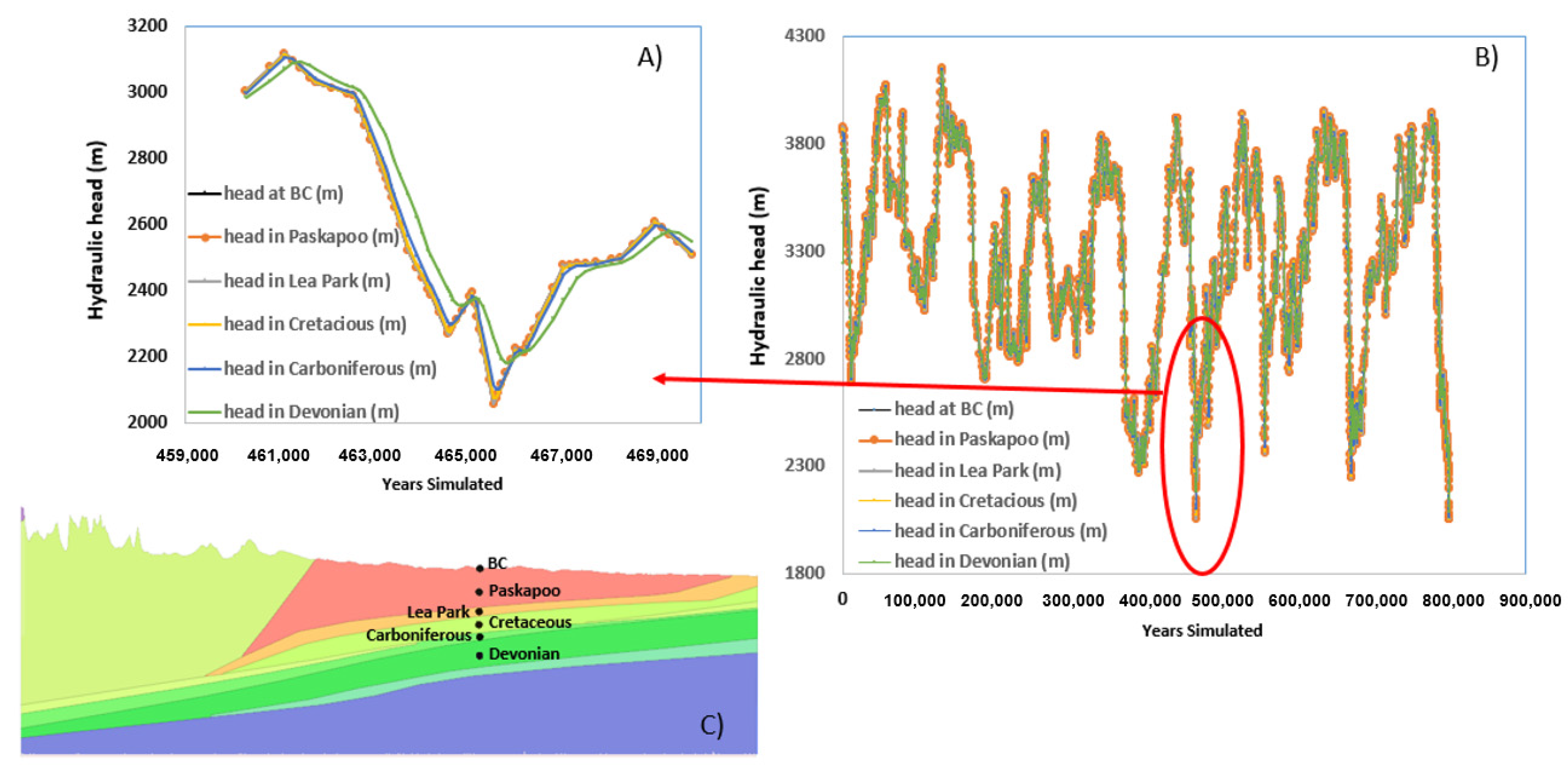
The simulation was run for just under 800,000 years, which coincides with the CO
2 record used to infer ice thickness. By observing
Figure 13A–C, we notice that the hydraulic heads are very closely related to the changing boundary condition over time. Looking more closely at
Figure 13A, it can be observed that there is a delayed response to the changing boundary condition in the deeper layers. Notably, the hydraulic head in the Devonian and the Carboniferous formations—which are the deepest formations observed—are the slowest to react to changes in the hydraulic head boundary condition. Steady-state is not reached in any of the formations following each pressure pulse induced by changes in the cyclic glaciation-deglaciation imposed as boundary condition onto the model at a rate of approximately 100k yr (see
Figure 9).
Thus, as expected, the presence of glaciers over the late Pleistocene (
Figure 9) has a transient effect on the groundwater heads of the upper most aquifers in model 1.
8. Sensitivity Analysis: Model Parameters
8.1. Sensitivity Analysis
A sensitivity analysis was performed to test the most important parameters that influence the flow entering the study area. The variation of the flow in the groundwater flow systems as a function of the variation of a few targeted parameters was carried out for multiple scenarios, including: variations in hydraulic conductivity (Paskapoo and Mountainous terrain), the presence of a conductive fault in the mountainous terrain, and anisotropy for the full model. The reference parameters (base case) are the ones provided in
Table 1. This sensitivity analysis was performed in model 1 only (Edmonton cross section) for the freshwater case.
It is widely recognized that most of the groundwater recharge in the study area takes place in the Foothills, the Main and Front Ranges, and mountains of the eastern Rockies Mountains [
11,
12]. However, given that precise recharge values in the mountains are not available, we represented the main gravity-driven hydraulic driver for groundwater flow in our three models, with a constant head BC, which was set equals to elevation at surface (
Figure 8). Thus, a sensitivity analysis of recharge is not possible.
8.1.1. Paskapoo
The hydraulic conductivity was first tested for the Paskapoo formation with K values ranging two orders of magnitude higher and lower than the base case value of 10
−5 m/s (
Table 4);
Figure 14 shows the results.
The results are shown with forward particles seeded in the Mountainous terrain east of the beginning of the Paskapoo Fm. As expected, the results show that travel times are faster than the base case for the two higher K values by factors of 1.8 and 2, respectively. The results for the two lower K values show much slower travel times than the base case, by factors of –55 and -2.5, respectively. These last two strikingly different values are explained by the fact that the particle in model1v4 follows a route through the Cretaceous and travels to the east, whereas the particle of model1v5 finds the Upper Cretaceous/Lea Park formation and leaves the system in the first valley located to the west in the Mountainous terrain.
8.1.2. Mountainous Terrain
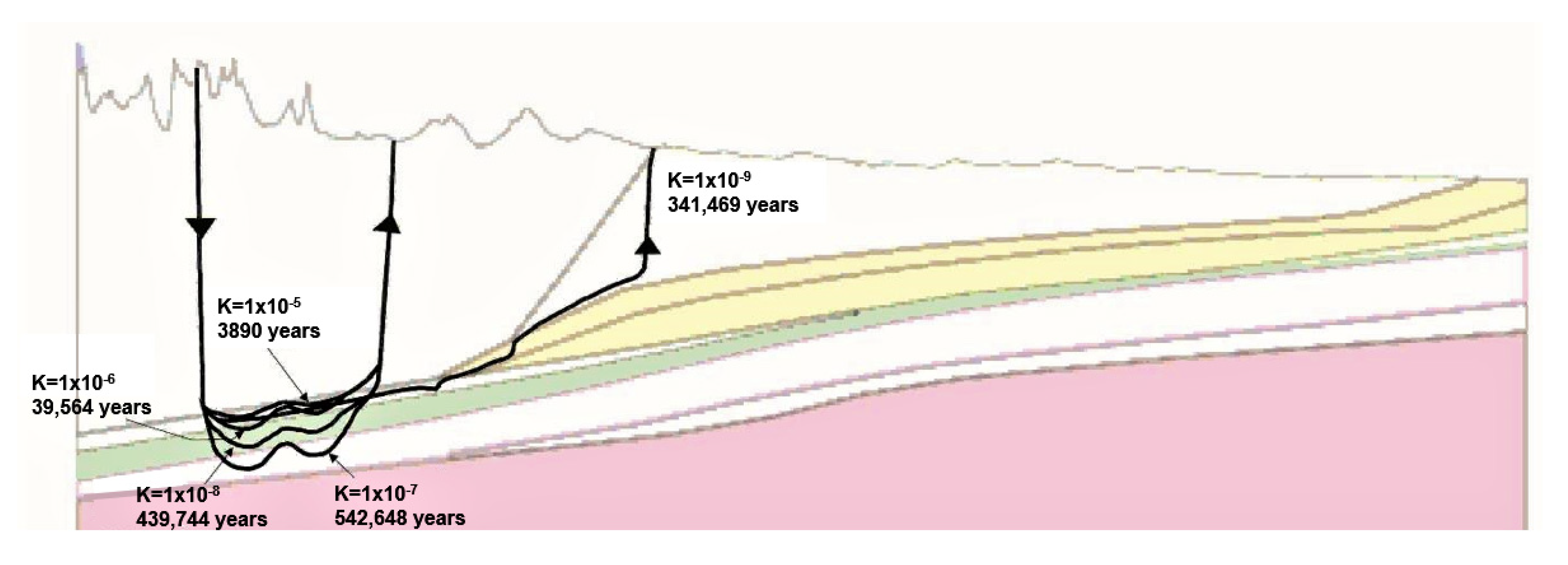
Variation in values of hydraulic conductivity was also tested in the Mountainous terrain with K values ranging two orders of magnitude higher and lower than the base case value of 10
−7 m/s (
Table 5);
Figure 15 shows the results.
The results are shown with forward particles seeded in the highest location in the mountains. The particles for the base-case scenario take more than half a million years to leave the multilayer system from the Mountainous terrain (
Figure 15). As expected, using higher K values, the results show that travel times are much faster than the base case; by enhancing the K values in the Mountainous terrain, the particles travel within the same formation leaving the system in the next lowest valley at ca 3.9ka and 39.5ka (
Figure 15). On the other hand, by decreasing two-orders of magnitude of the K values in the Mountainous terrain, the particles find different routes and their travel times remain close to the base case.
Figure 15 shows that the particles for model1v4 follow a very similar route as the base case, crossing the Jurassic and Devonian before reentering the Mountainous terrain. Similar to the base case, the particles for model1v5 travel vertically toward the Jurassic but find the Upper Cretaceous and the Paskapoo Fm where it leaves the system after 341ka.
8.1.3. Presence of a Fault
Regional-scale groundwater flows may be impacted by deformation along faults in the shallow crust (less than 1 km), which introduces permeability heterogeneity and anisotropy. The capacity of fault zones to be a hydraulic conduit connecting shallow and deep geological environments, was demonstrated by Bense et al., [
45], who also showed that the fault cores of many faults often form effective barriers to flow. To test both effects with the presence of faults, we simulated the sensitivity of our models by placing a general (not specific) schematic fault to test the sensitivity of this feature to the numerical model.
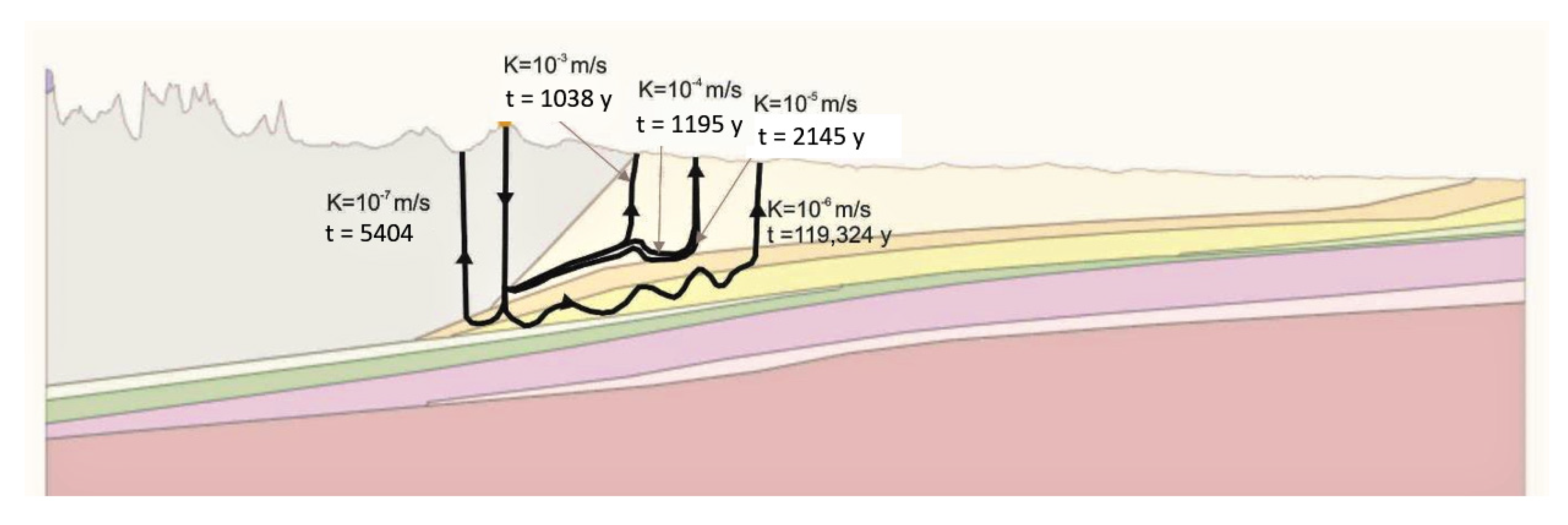
A high conductivity fault was placed between the Mountainous formation and the Paskapoo formation. The hydraulic conductivity was varied between 10
−7 and 10
−3 m/s where 10
−3 m/s represents a very high conductivity fracture and 10
−7 m/s represents the same value for hydraulic conductivity as the Mountainous formation (
Table 6).
Flow directions and travel times were observed for each scenario (
Figure 16). For values between 10
−5 m/s and 10
−3 m/s the chosen particle flows eastward with travel times ranging, respectively, from 124 756 years to 3420 years. For K values of below 10
−5 m/s the flow direction is reversed to the West with travel time values ranging between 17,687 and 20,493 years. It is apparent that fractures can have a profound effect on travel times and flow directions.
8.1.4. Anisotropy
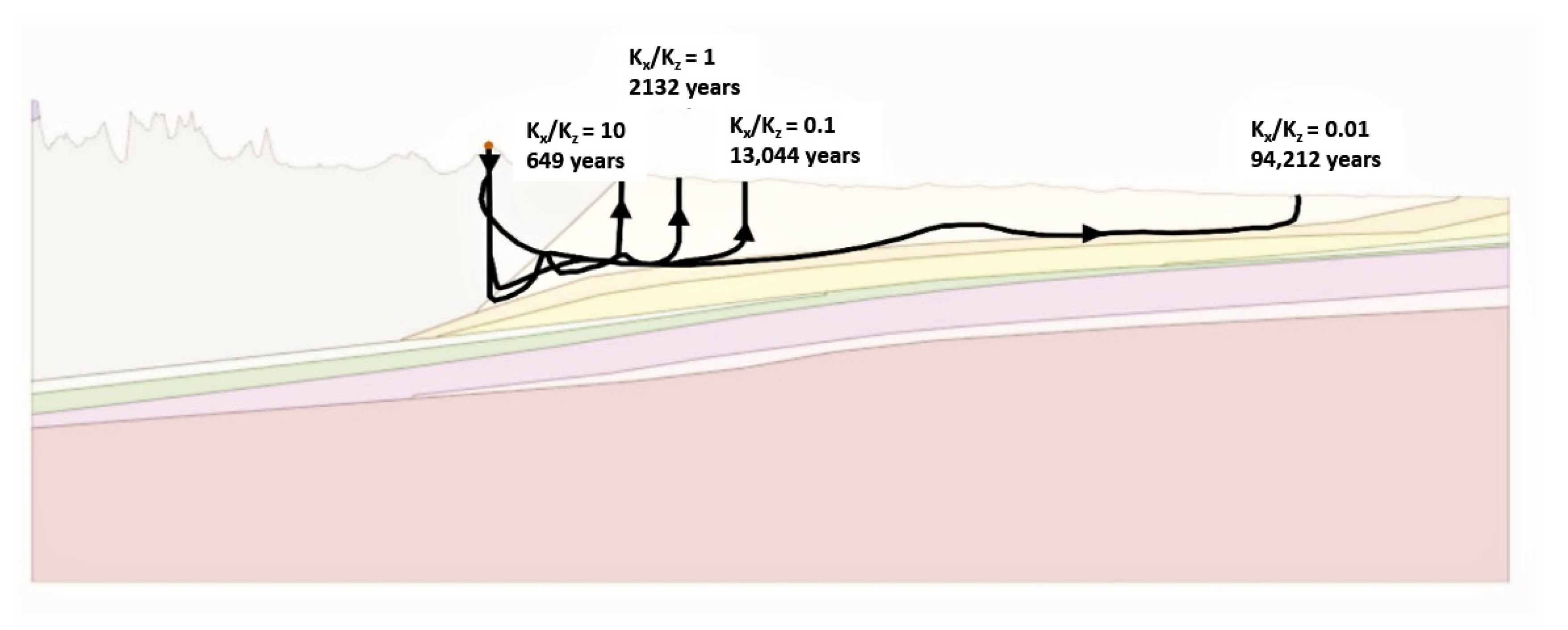
In the base case, the ratio of vertical to horizontal conductivity for the entire model is Kx/Kz = 1. Three other ratios were tested to evaluate the effects of anisotropy: 0.01, 0.1 and 10 (
Table 7) and the preferential flow directions.
Figure 17 shows the results.
Particles seeded in the highest peak in the Mountainous terrain closest to the Paskapoo Fm, follow a vertical direction within the Mountainous terrain, and a horizontal flow as soon as they reach the Paskapoo Fm. It takes in the order of 2100 years for the base-case particles to leave the system vertically in the Paskapoo. Particles in model1v4 take the same direction as the base case but are three times faster to leave the system due to the horizontal hydraulic conductivity (Kx) being 10 times greater than vertical hydraulic conductivity (Kz), enhancing the process of subsurface lateral flow.
The other two lower-ratio models follow the same route too but are slower than the base case to leave the system, with model1v1 being the slowest with 94.2ka due to the much higher vertical K value.
9. Groundwater Flow Systems
The partition of the study area into sub-flow regions helps to target the major groundwater flow systems (GWFS) and compare one model to another. The division of flow systems has been performed by other authors [
45,
46,
47] using field data and modelling. Nevertheless, this approach has yet to be tested with numerical data alone.
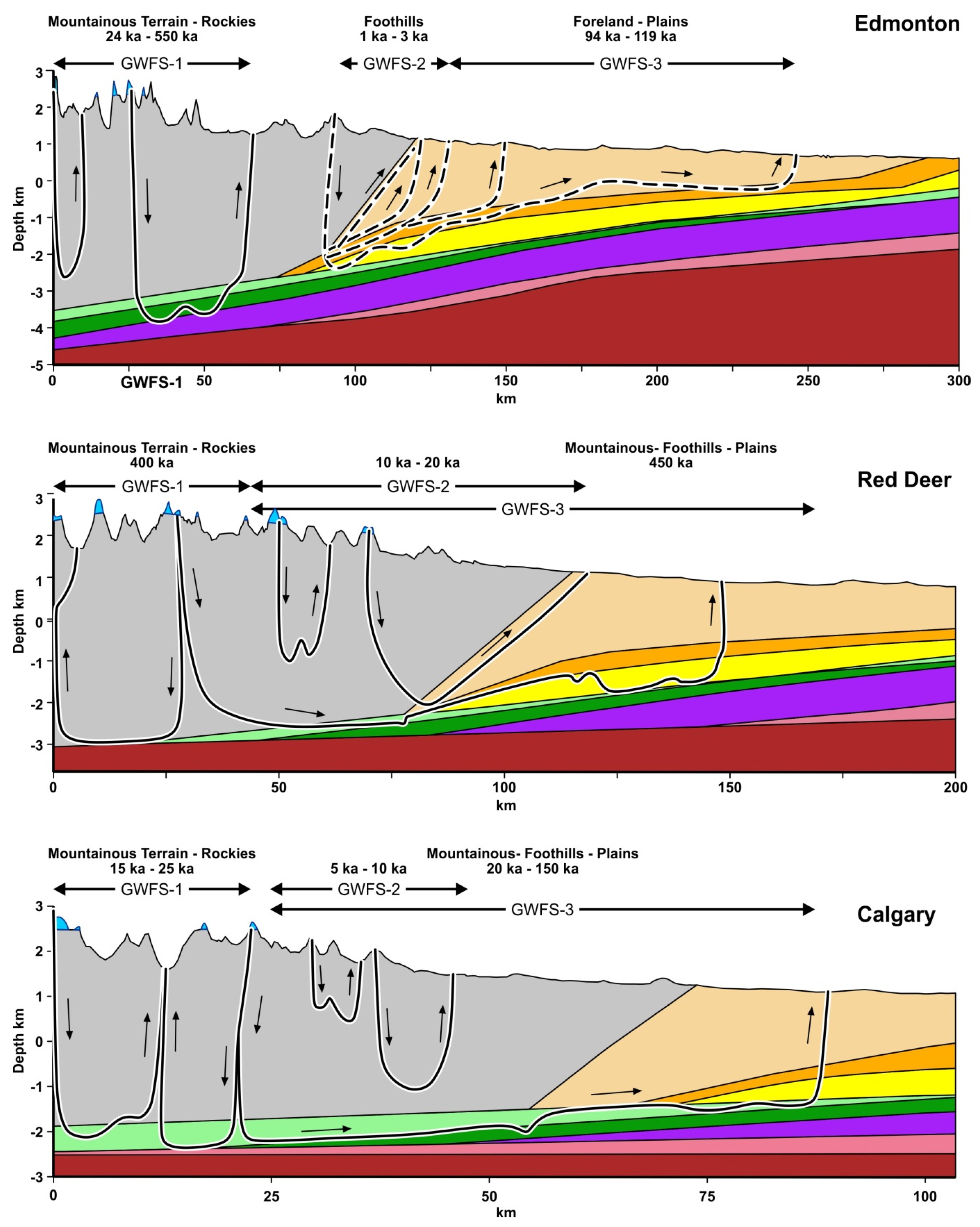
For the purpose of this study, an approach was adopted by evaluating the streamlines behavior for some of the simulated cases shown in
Table 2. A distinction was made for three groups of similar behavior across the three two-dimensional models. This method was applied to all three hydrogeological models in the steady-state freshwater base-case scenario, as presented in
Figure 18, and for a few results of the parameter sensitivity analysis applied to model 1 only.
The results of the groundwater flow systems show three distinct flow regions for the three cross sections, as outlined in
Figure 18. The flow paths for GWFS-1 in the three models are spread out 20 to 100 km across the Mountainous terrain and vary between 15ka to 550ka. The large differences in the advective times are due to three factors; the length and thicknesses of each model, the contrasts in hydraulic conductivity of the layers in contact with the Mountainous terrain, and the topography of the mountains for each model. For instance, model 1 (Edmonton) is the one with the largest range of advective times, whereas model 3 is the shortest.
The thickness of the Mountainous terrain of model 3 (Calgary) is circa 4 km and its length only 50 km. In addition, in model 3 the Mountainous terrain is in direct contact with the Jurassic Fm (K = 10−7 m/s) all along its length. Groundwater originated in the glaciers located in model 3, takes 15ka to 25ka to travel 4 km vertically and 5 to 10 km horizontally, before it finds its outlet in the valleys within the Mountainous terrain.
The timings of the flow paths for GWFS-2 are essentially located in the foothills for model 1, between the foothills and the Plains in model 2, and within the Mountainous terrain in model 3. The advective travel times for GFWS-2 are in the range of 5ka to 20ka in models 2 and 3 as indicated in
Figure 18.
The flow paths of the third groundwater flow system (GWFS-3) are streamlines originating in the highest peaks of the Mountainous terrain that travel deeper into the multilayered system, and longer horizontally through the layers. The flow paths in model 2 take hundreds of thousands of years to travel in the GWFS-3 before they reach the outlets in the Paskapoo Fm. It takes 450ka to travel 150 km in model 2 (Red Deer), and 150ka to travel 60 km in model 3 (Calgary). No similar flow path system is observed in model 1 (Edmonton). The travel times for other paths originating in lower peaks in model 3, find the Jurassic and Carboniferous layers (K = 10−8 m/s) and travel through the foothills and the Plains until they find the lowest elevation in the Paskapoo Fm, after 150ka.
The results of three cases of the parameter sensitivity analysis for model 1 are also used in the GWFS analysis: effects in the variation of conductivity for the Paskapoo Fm, presence of a conductive fault, and anisotropy effects. The results of flow paths for the sensitivity analysis are shown only on model 1 (Edmonton) as dashed lines in
Figure 18. The effects of the variation of K in the Paskapoo Fm, and the presence of a fault are seen mostly within the foothills with travel times between 1ka and 3ka. Decreasing the hydraulic conductivity of the Paskapoo Fm of one order of magnitude (K = 10
−6 m/s), increases advective travel times one hundred times; this is due to the fact that the flow paths travel vertically through the upper Cretaceous (Lea Park), which underlies the Paskapoo Fm and take much longer times to travel horizontally.
An interesting result is shown for the case of anisotropy of Kx/Kz = 0.01; the travel time strongly increases to 94ka (longest dashed line in
Figure 18) relative to the base case, due to the twofold increase in vertical conductivity.
From the results of these models, a map of the GWFS was derived by joining the limits of each cross-section GWFS’ coordinates. The three GWFS are shown on the two-dimensional horizontal map of the study area in
Figure 19, with lines of approximate equivalent flows and associated travel times. Without being precise flows, this horizontal presentation of groundwater flow systems helps illustrate lengths of flow patterns within the geological and hydrogeological context of the study area, helping visualize how far and for how long groundwater from the eastern CRM travel into the Plains region. It is a numerically-modeled look of how the eventual melting of glaciers in the Rockies would affect groundwater in the Plains region. These results show that the glaciers from the eastern CRM are not the main geological source of groundwater for the aquifers located in the Plains at the regional scale and the human scale.
10. Discussion
10.1. On the Conceptual Numerical Modelling
Conceptual hydrogeological numerical models are excellent tools to simulate groundwater flow in complex settings and with coupled phenomena at large scales, such as groundwater flow and mass transport, and to forecast the fate of water following glacier melt.
Given the depth of the numerical models developed in this study, there was no attempt to calibrate these conceptual models. The depths of wells in the study area are less than 300 m deep for bedrock, mainly in the sandstone formations. These depths only cross the uppermost layer in the models. Thus, the models cannot be calibrated against water levels; nonetheless they were verified against other similar studies in the region and against analytical solutions.
This study uses three 2D large numerical models hundreds of kilometres long and several kilometres deep, to investigate the groundwater flow of glacial melt in the Canadian Rockies and potential effects on groundwater in the Plains region. Other conceptual modelling studies in the region include the relations between in situ groundwater storage change observations in Alberta, with precipitation and GRACE-derived groundwater storage changes [
14]; glacial melt and associated changes on downstream flow systems, infiltration into the ground, and their potential impacts on water resources in the CRM using GRACE and glacial mass balance modelling [
2]; and geothermal flow in deep sedimentary basins in Alberta to forecast the productivity of geothermal reservoirs with a coupled numerical model [
15].
The numerical results for the time scales of groundwater flow are comparable to the response times provided by analytical solutions (see next sub-section). The conceptual regional-scale numerical models are based on the current knowledge of the hydrogeology of the study area. Typical hydrogeological parameter values of the main geological formations are used in the models.
10.2. On the Response Times
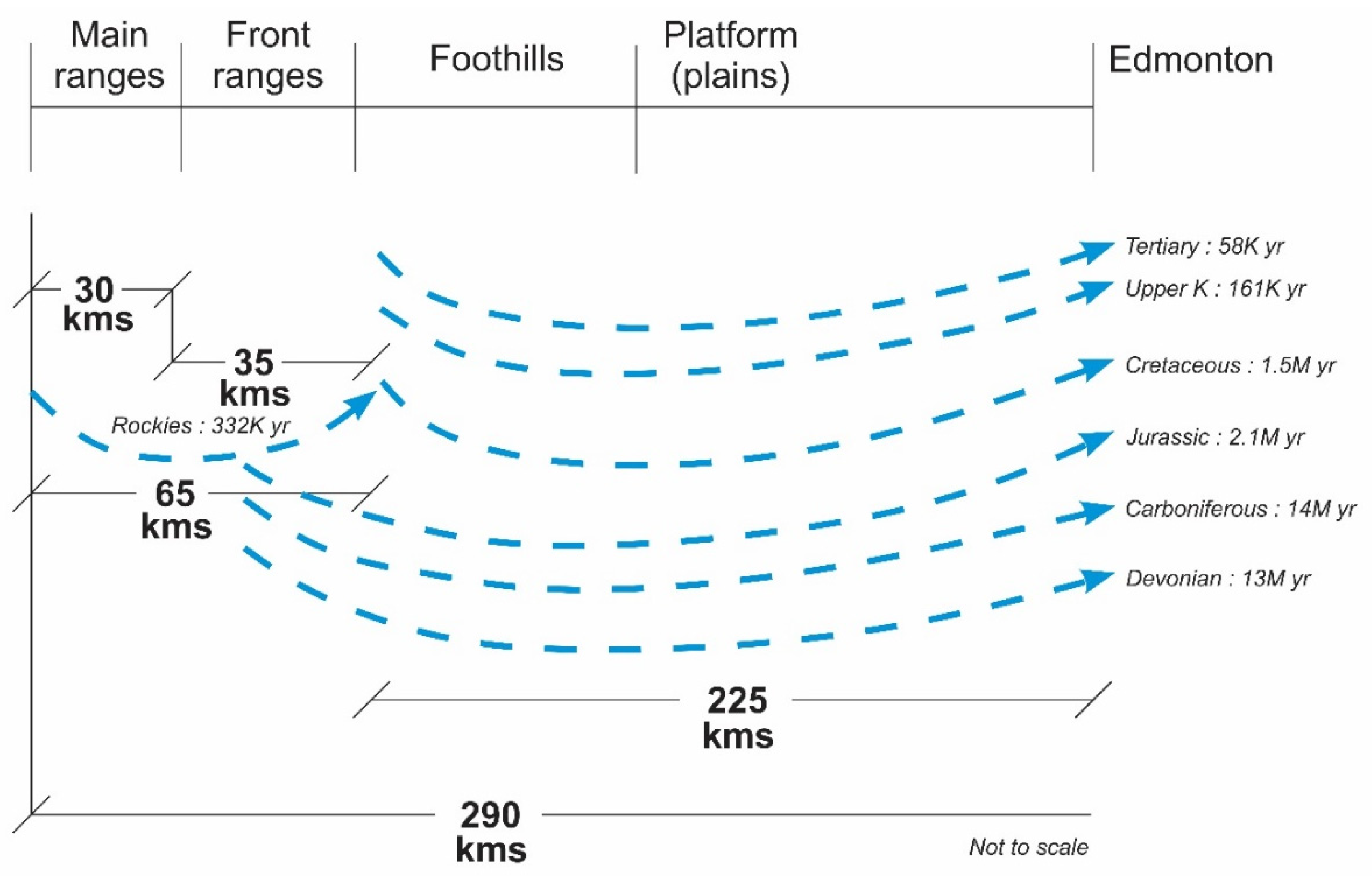
To complete the analysis of the groundwater flow systems (
Figure 18 and
Figure 19), in addition to particle tracking that provides transit time, we calculated the response times as well—the time for a pressure pulse, or large hydraulic perturbation, to reach a near-steady state condition. The present hydraulic heads in the multi-layer aquifer-aquitard system analyzed in this study, may be the response induced from current and past hydrologic conditions in the region, including glacial-interglacial changes (100 ka cycles, [
48]).
To estimate the time to reach a near-equilibrium state in aquifers following a large hydraulic perturbation (such as glaciations), an analytical solution of the flow equation with the diffusivity concept can be used [
49,
50,
51]. The analytical solutions make use of the diffusivity factor for example by using the simple relation response-time = L
2/D with L = distance to travel and D is the aquifer diffusivity D = T/S, with T = transmissivity and S = storage coefficient.
In these solutions, near-equilibrium (or near-steady state) is defined as the time for an initial aquifer perturbation to dissipate by an average 95% across the aquifer. The analytical solution has been obtained by solving the flow system of a simplified conceptual model of a mixed aquifer using Laplace transforms [
51]. The conceptual model is based on two assumptions: (1) the groundwater flow can be reduced to a horizontal 1-D problem and (2) the transmissivity, a function of the saturated thickness, is assumed constant on the unconfined portion.
Following a large hydraulic perturbation, changes in recharge, discharge, or hydraulic parameters can result in the groundwater system being in disequilibrium which will initiate some transient groundwater behavior. Different mechanisms such as geologic processes or morphologic and climatic variations can lead to hydrodynamic changes [
51]. Transient behaviors of groundwater systems are related to a balance between the origin of the perturbation (e.g., glaciers) and the resulting flows, which tend to dissipate it. A major control of this dissipation is the aquifer diffusivity, the ratio of aquifer transmissivity to storativity.
Using the approach described by Rousseau-Gueutin et al. [
51] for long aquifers (L > 10 km), we estimated the time constant to reach near-equilibrium for each layer.
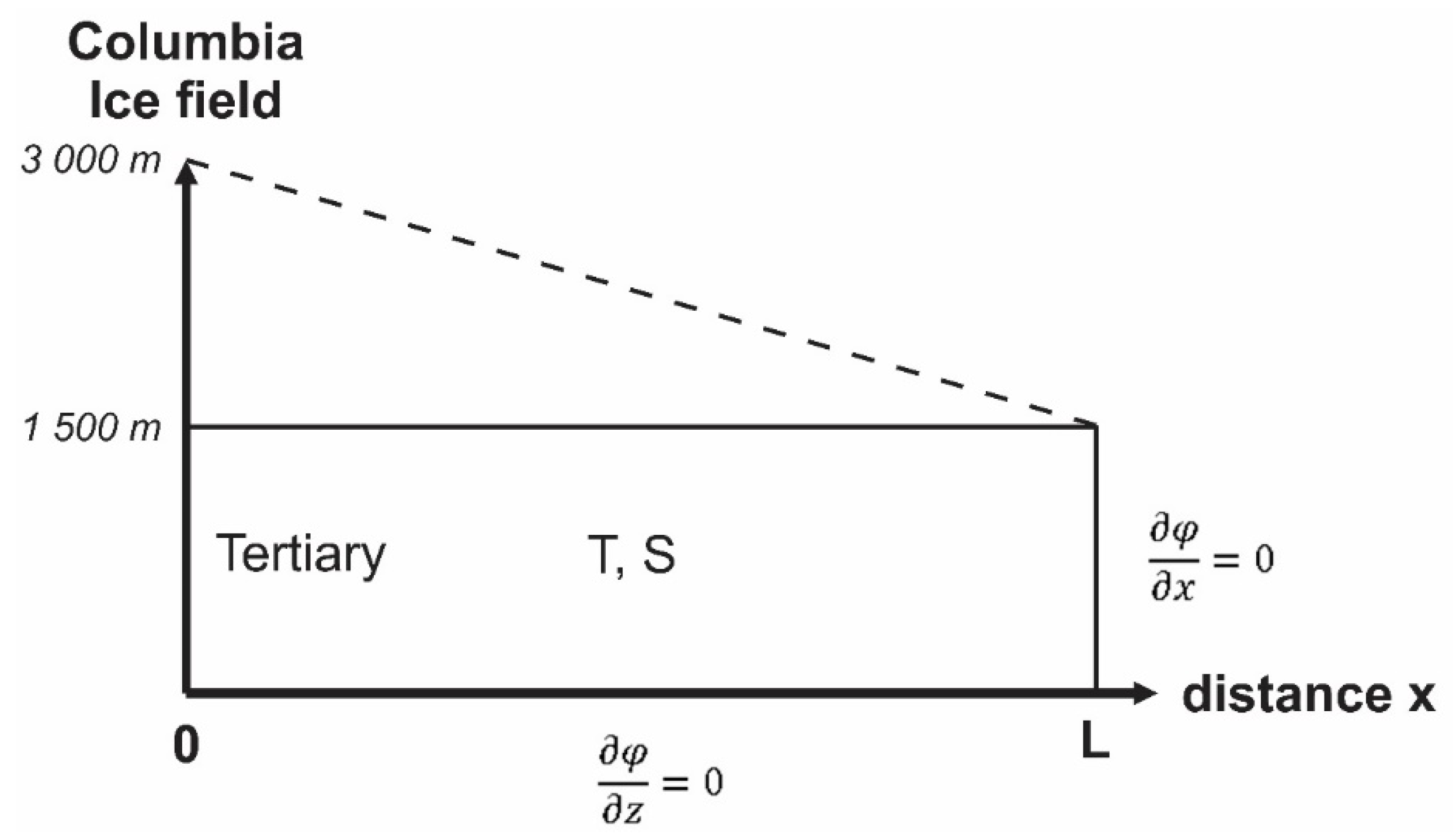
Figure 20 shows a schematic conceptual model for the conditions of the Tertiary and top Cretaceous above Lea Park (Paskapoo and Edmonton Gp.). For this case, we considered the Dupuit approximation, which states that for long aquifers the vertical component of the velocity can be neglected and the problem reduces to a 1-D one, along the horizontal distance
x, where the hydraulic potential satisfies the diffusion equation:
where ν is the hydraulic potential, and D is the hydraulic diffusivity defined by D = K/S
s = T/S.
An analytical expression for the time constant, ϑ, was proposed by Domenico and Schwartz [
30] for a homogeneous, isotropic and fully confined aquifer with a purely horizontal flow:
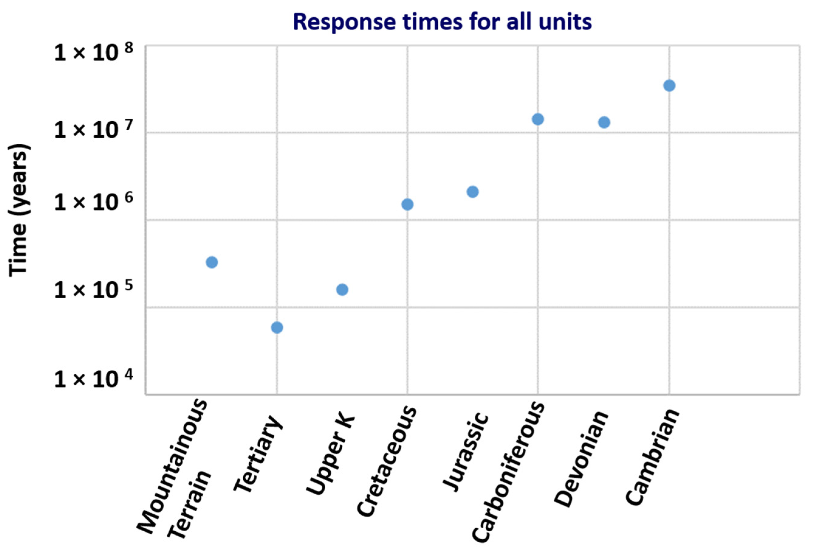
This solution was used to estimate the time to reach near-equilibrium in each of the geological formations in our study area. For those formations, the time to reach near equilibrium ranges between thousands to hundreds of thousands of years to millions of years (
Figure 21). These results suggest that the present hydraulic heads in these aquifers and aquitards are typically a mixture of responses induced from current and past hydrologic conditions and thus climate conditions. For some aquifers, the modern hydraulic heads may in fact depend upon hydrologic conditions resulting from several past climate cycles (glaciations).
Only the hydraulic heads in layers within the Tertiary and top Cretaceous (Paskapoo and above Lea Park) formations are likely the result of the last glaciation. The diffusivity of these layers falls in the range of 0.1 to 0.01 m
2/s, respectively; maximum times of 58 ka and 161 ka are needed to reach a near-equilibrium state (
Figure 21).
Using parameters and lengths of the layers in model 1 (Edmonton) for the base-case simulation, we estimated the transient times needed to reach near steady-state conditions for each layer. The results are plotted in a schematic view in
Figure 22. The travel times for all the layers below the upper Cretaceous fall in the range of 1 to 14 million of years to travel through the Front ranges, Foothills and Platform (Plains) to the city of Edmonton. Thus, it is likely that only the groundwater flowing in the Paskapoo Fm (Tertiary) and Upper Cretaceous (above Lea Park) is from the Rockies as a result of a hydraulic perturbation (recharge) following the last climatic transition (glaciations).
Using a different approach, Castellazzi et al. [
2] suggested that the response time of surficial aquifers is rather short with tens of years while deeper aquifers in mountainous terrains are in the order of thousands of years. For deeper aquifers, they further suggested that groundwater remains stored in the mountainous terrain for longer periods of time. Our modelling results confirm these assumptions for the deeper aquifers.
Our modelling results illustrate that groundwater resources in the Plains are not likely affected by the recent melting of glaciers in the eastern CRM.
10.3. On the Sensitivity of the Adopted Models
In the 2D models, the Paskapoo Formation was conceptualized as an aquifer system, integrated with the Tertiary/Top Cretaceous and above Lea Park, assigning a single value of hydraulic conductivity K; however, it is well known that this formation is extremely heterogenous. Values of K for the Paskapoo were tested with two-orders of magnitude higher and lower than the base case in the models, which more or less cover the range of known K values of for the Paskapoo. Further, testing the sensitivity to anisotropy for the whole model was helpful in understanding the very important role of the Paskapoo in the regional layered system. Mimicking heterogeneity through conceptualizing as a highly layered system demonstrates that flow systems could extend into the plains. To further test the Paskapoo, an improvement would be to split the Paskapoo layer into 3 sub-layers (high-K; low-K; high-K) but testing a detailed Paskapoo formation was beyond the purpose of this study.
The uncertainties on the conceptualization and adopted parameters of the mountains block may be high. Unravelling the complexity of the hydrogeological conceptual framework proposed in this study through future research would help close a gap in knowledge identified by the authors in this regard.
Other limitations of these 2D conceptual numerical models include the changing topography and surface drainage systems. It is acknowledged that a more rigorous modelling approach could have been changing the upper boundary condition to mimic the surface drainage systems reconfigured with each glacial cycle; the approach used with modern-day topography as a specified upper hydraulic boundary may only represent recent timeframe. Since we did not have precise horizons of the topography over the last 800k years, we opted for an upper boundary condition equals to topography and observed that, at the regional scale, factors other than the topography were more important. Lastly, the simple analytical solution compares well with the results of the numerical models, which provides confidence in the adopted numerical models.
11. Conclusions
We have developed a series of three numerical models in two vertical dimensions across the eastern CRM and the Plains, kilometers in the vertical dimension and hundreds of kilometers in the horizontal dimension. The three cross sections are parallel to the west-east topographic gradient in the region, which allows a two-dimensional approximation of a three-dimensional flow system.
The numerical simulations, based on the current knowledge of the hydrogeology of the region, show that it is highly unlikely that the current melting of glaciers affect groundwater in the Plains in the immediate future. The contribution of glaciers water in the eastern part of the Rockies is time-dependent with delayed groundwater flows of 100s of years in the front ranges, 1000s of years in the foothills; and 100,000s to millions of years to the Foreland at the regional scale.
The presence of glaciers in the eastern part of the Rockies contributes very little groundwater flow to the foothills and nothing to the Foreland at the regional scale. The melting of those glaciers, however, may have a shorter-term contribution to the base flow of rivers whose source originate on the mountainous terrain and drain each side of the Rockies, as shown by previous and recent studies.
Most of the water originating at the base of the glaciers is discharged locally through the lower slopes of the valleys and valley floors in 10s to 100s of years; only minor amounts of water that infiltrate deeper are left for longer and deeper groundwater flow systems reaching the foreland in millions of years.
These results are important for a variety of calculations ranging from estimates of local and regional groundwater availability believed to have their sources in the Rockies’ glaciers. Knowing the ice mass losses in the glaciers and their effects in the Canadian Plains is crucial for projecting any future development of groundwater.
At the human scale, groundwater resources in the Plains are not likely affected by the melting of glaciers in the eastern CRM.
Simple analytical solutions to estimate the time to reach a near-equilibrium state in aquifers, using the hydraulic diffusivity concept, reach similar conclusions to the numerical simulations.
Finally, based on these modelling results, it is very unlikely that modern satellites (e.g., GRACE-FO) detect additions or subtractions of groundwater in the Canadian Plains at the human scale, as a consequence of melting of glaciers in the Rockies.
