Author Contributions
Conceptualization, R.T., J.W. and B.Z.; methodology, R.T., B.Z., S.F. and J.W.; software, S.R., J.W., J.H. and R.T.; validation, M.A., G.U., B.Z. and J.W.; formal analysis, R.T. and B.Z.; investigation, R.T., J.H., S.F. and B.Z.; resources, M.A., B.B. and G.U.; data curation, R.T., S.R. and J.W.; writing—original draft preparation, R.T.; writing—review and editing, R.T., J.H., S.F., G.U., B.Z., J.W., S.R. and M.A.; visualization, R.T., S.R. and J.W.; supervision, M.A. and B.B.; project administration, M.A., B.Z., R.T. and B.B.; funding acquisition, M.A. and B.B. All authors have read and agreed to the published version of the manuscript.
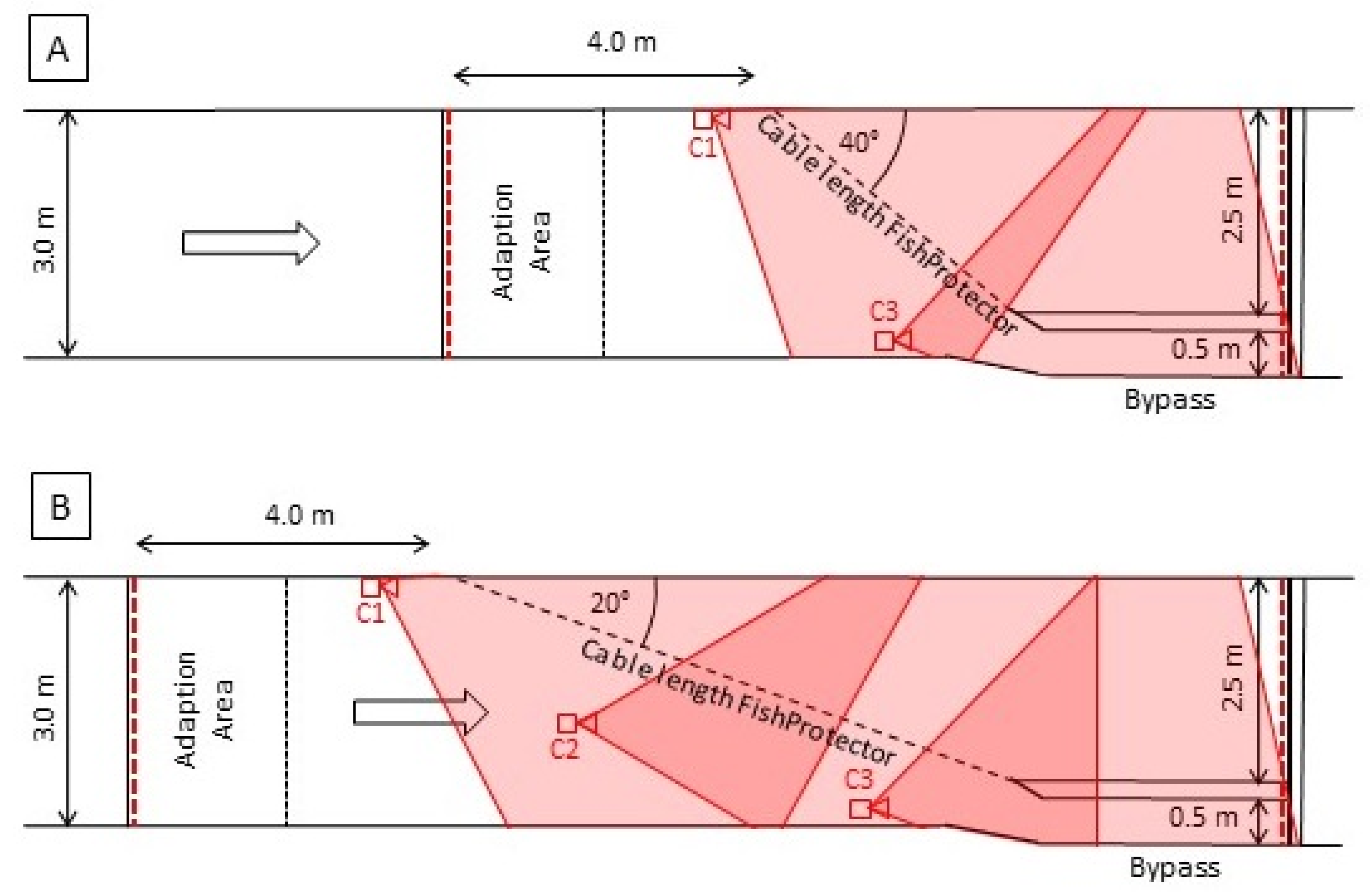
Figure 1.
Design of the 3.0 m-wide experimental area with the two investigated exposition angles, 40° (A) or 20° (B), with two or three cameras (depending on the cable length of the Flexible FishProtector C1 and C3 or C1–C3) with the covered areas of the cameras shaded in red. Red dashed lines show the limits of the experimental area, the black dotted line (grid) shows the limit of the adaption area, and the grid was pulled after the adaption time of 0.5 h.
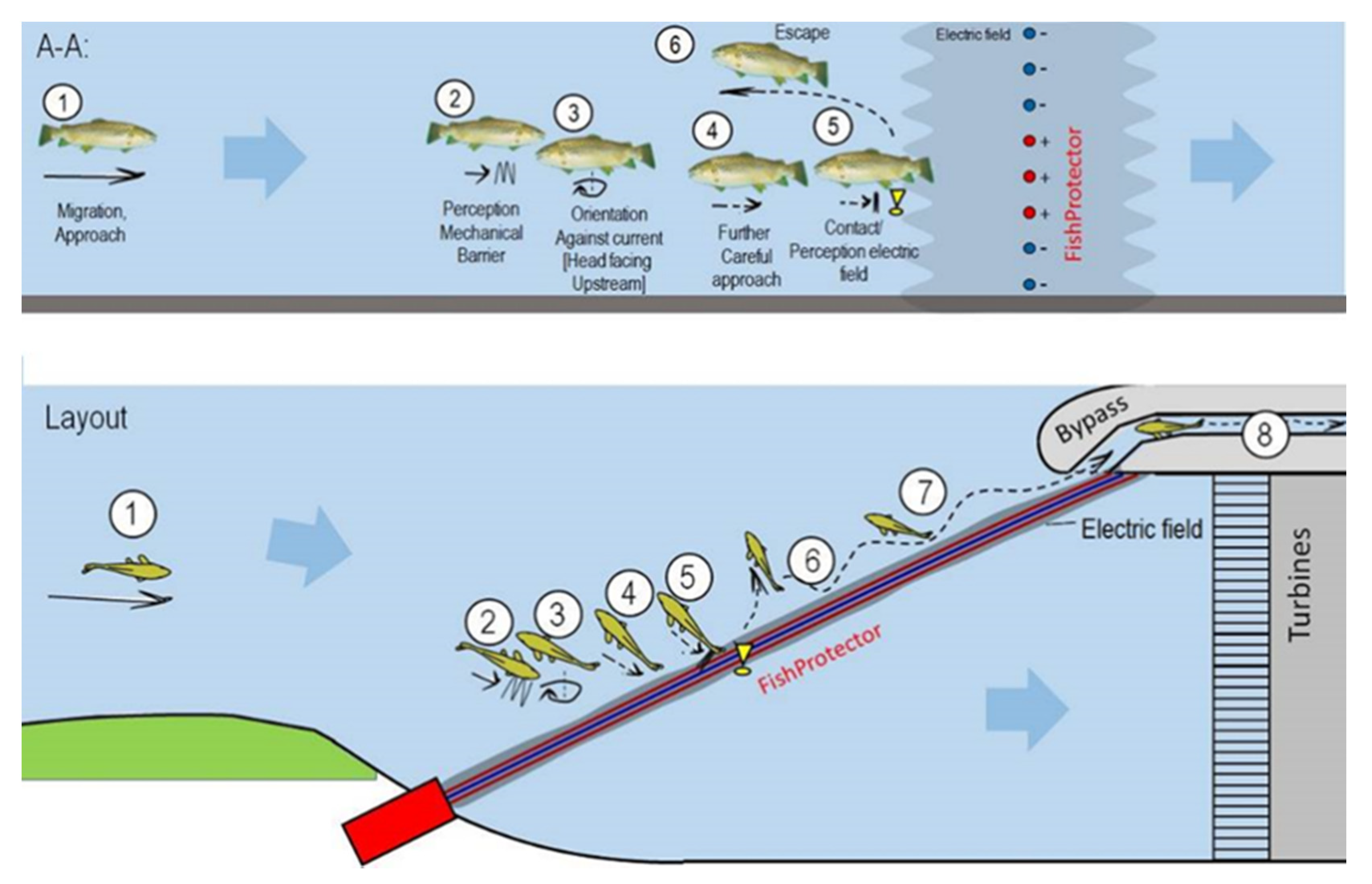
Figure 2.
Fish protection principle at the hybrid barrier Flexible FishProtector: interaction of the physical barrier and the behavioral barrier. Numbers from 1 to 8 indicate the sequence of fish behavior when fish approach the Flexible FishProtector. (1) Downstream migration, (2) perception of physical barrier, (3) rheotactic swimming position, (4) approaching FishProtector, (5) entering electric field, (6) flight reaction, (7) guiding, and (8) bypass use. Protection principle shown in A-A as section and underneath as layout. Source: Aufleger, 2019 [
41].
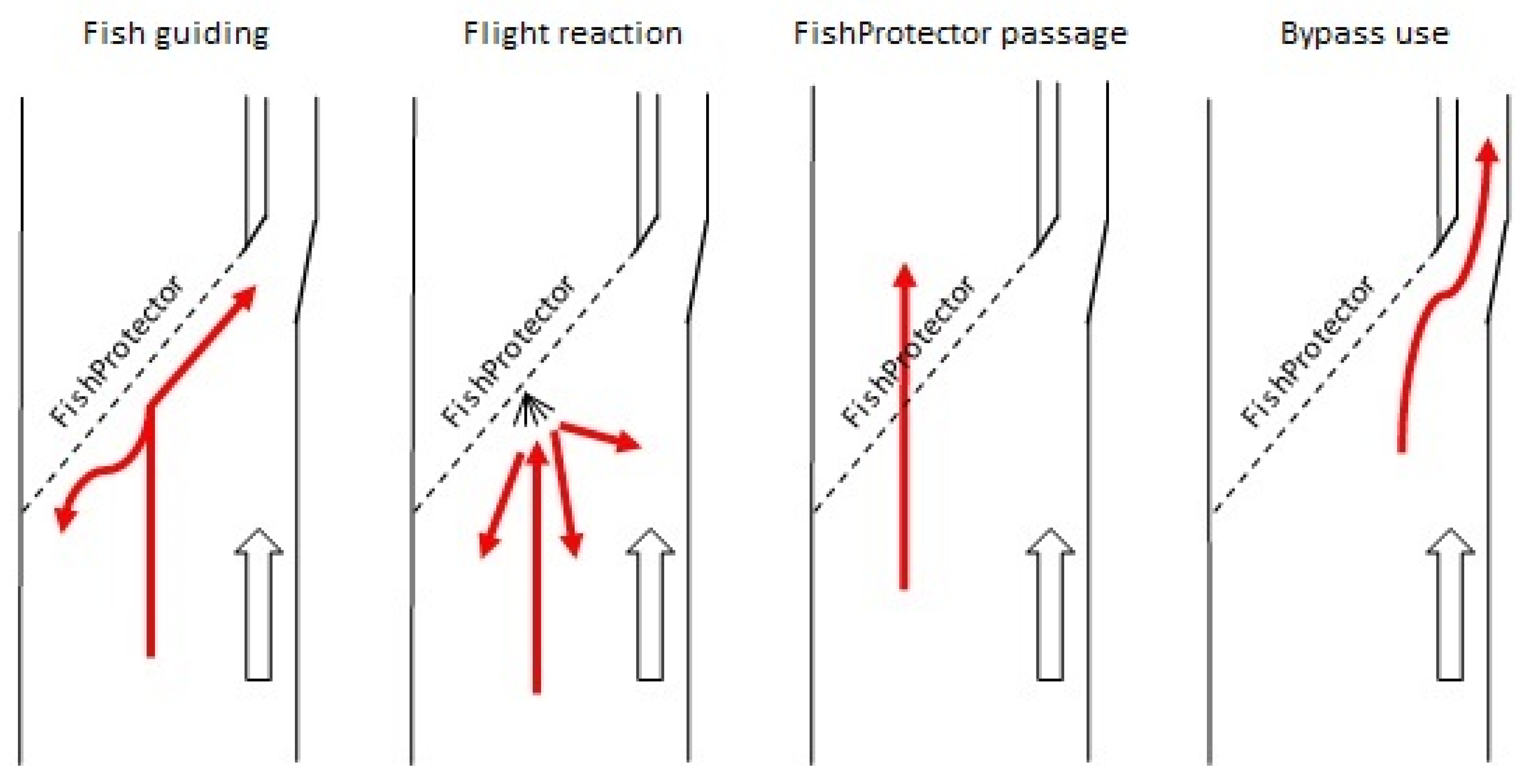
Figure 3.
The four behavioral categories that were used in the (statistical) analysis are visualized in the sketch of the experimental layout: fish guiding, flight reaction, FishProtector passage, and bypass use from left to right. The fish movement is shown in red, while the white arrow denotes flow direction. The physical and behavioral barrier are indicated by the dashed line.
Figure 4.
Guiding activities along the Flexible FishProtector per fish, dependent on the setups with the parameter exposition angle (°), cable clearance (mm), and electric field (no electric field (white), small electric field (light gray), large electric field (dark gray)). A single boxplot represents robust statistical measures, such as minimum, 1st quartile, median, 3rd quartile, maximum, as well as extreme values defined as 3rd quartile plus 1.5 times the interquartile range, interquartile range equals 3rd quartile minus 1st quartile.
Figure 5.
Decision tree for guiding along the Flexible FishProtector per fish showing the importance of the parameters. Following the left branch at a split always means “yes” for the stated parameter value, while following the right branch at a split means “no”. In the boxes, the corresponding mean guiding per fish is provided as well as the number of experiments and its percentage of all experiments.
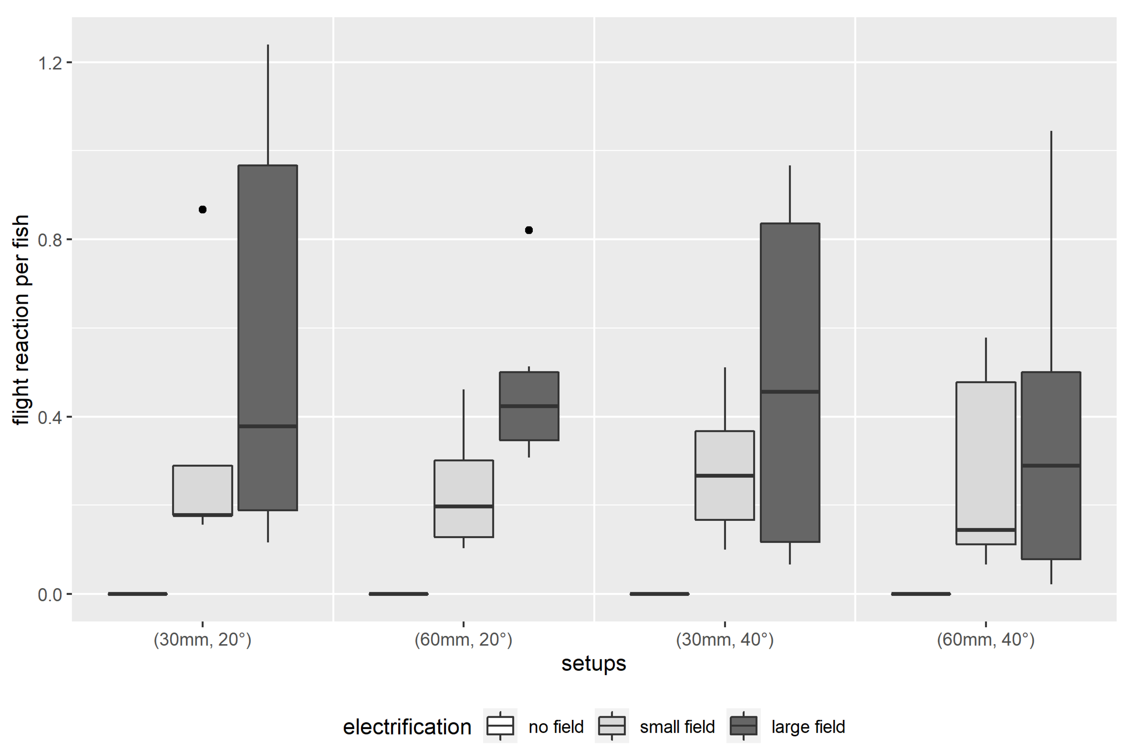
Figure 6.
Flight reactions per fish dependent on the setups with the parameter exposition angle (°), cable clearance (mm), and electric field (no electric field (white), small electric field (light gray), large electric field (dark gray)). A single boxplot represents robust statistical measures, such as minimum, 1st quartile, median, 3rd quartile, maximum, as well as extreme values defined as 3rd quartile plus 1.5 times the interquartile range, interquartile range equals 3rd quartile minus 1st quartile.
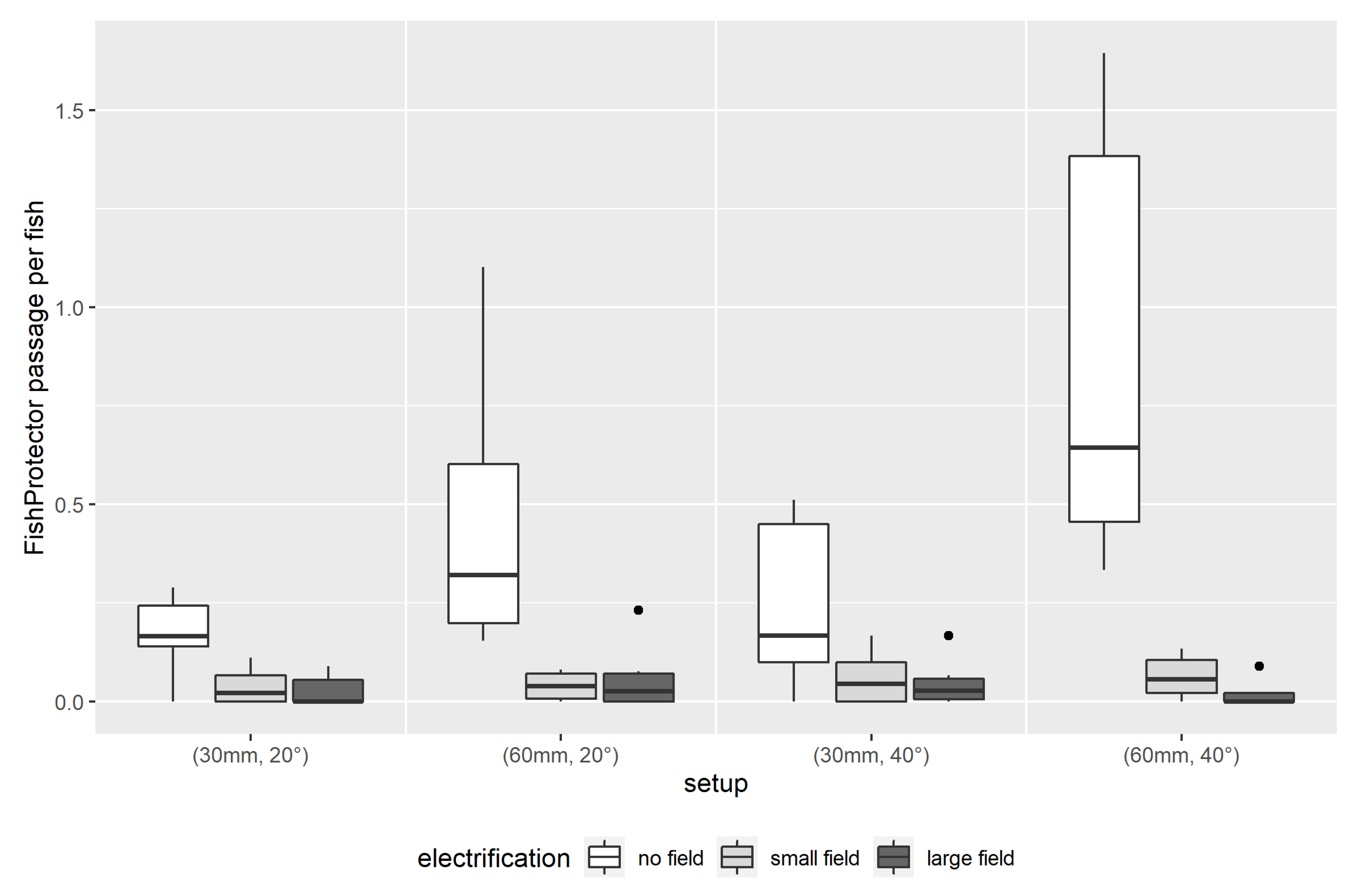
Figure 7.
FishProtector passages per fish dependent on the setups with the parameter exposition angle (°), cable clearance (mm), and electric field (no electric field (white), small electric field (light gray), large electric field (dark gray)). A single boxplot represents robust statistical measures, such as minimum, 1st quartile, median, 3rd quartile, maximum, as well as extreme values defined as 3rd quartile plus 1.5 times the interquartile range, interquartile range equals 3rd quartile minus 1st quartile.
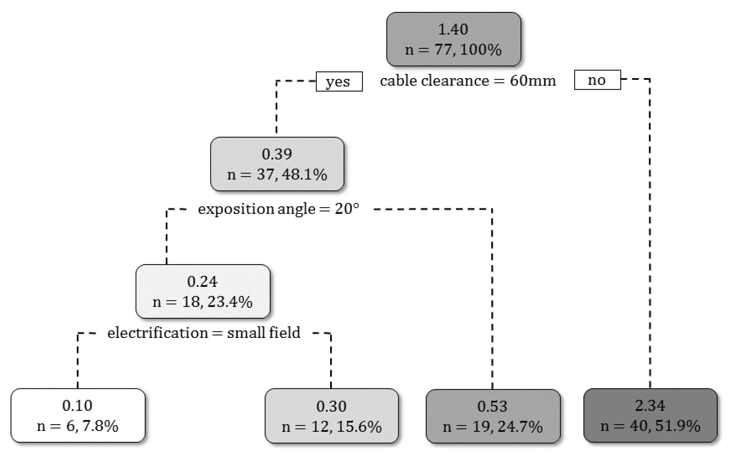
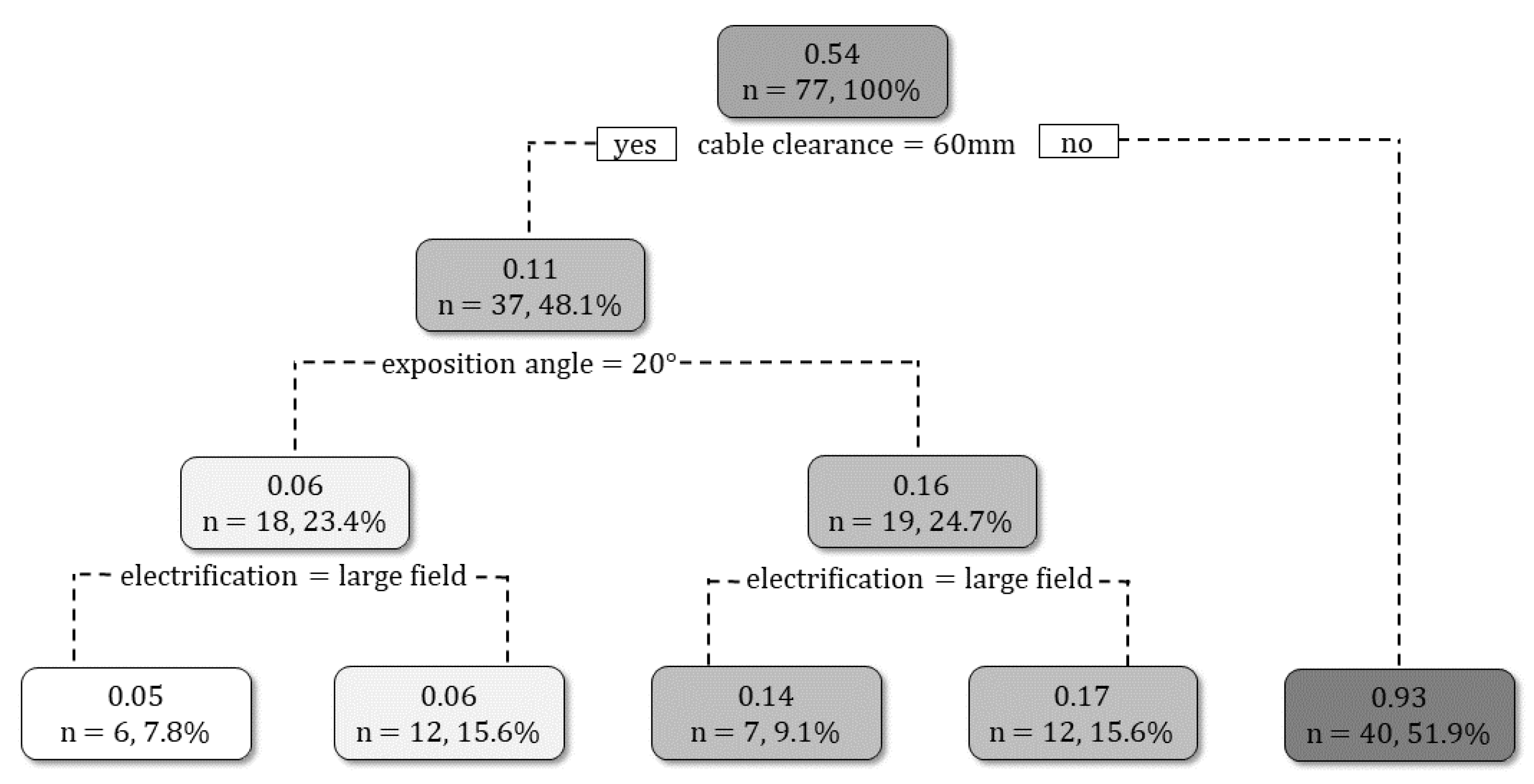
Figure 8.
Decision tree for FishProtector passage per fish showing the importance of the parameters. Following the left branch at a split always means “yes” for the stated parameter value, while following the right branch at a split means “no”. In the boxes, the mean passages per fish are provided as well as the number of experiments and the percentage of all experiments.
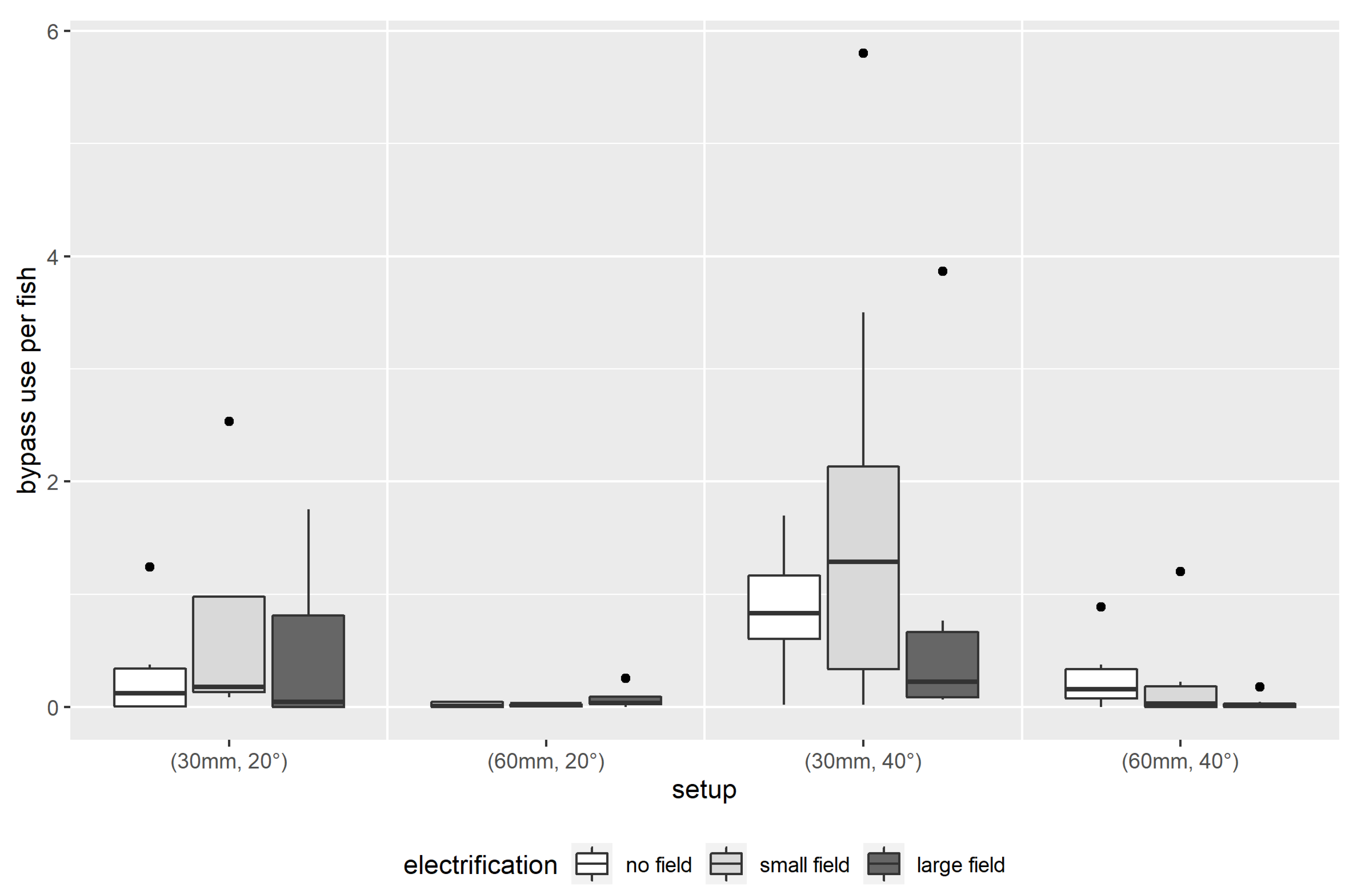
Figure 9.
Bypass use activities per fish dependent on the setups with the parameter exposition angle (°), cable clearance (mm), and electric field (no electric field (white), small electric field (light gray), large electric field (dark gray)). A single boxplot represents robust statistical measures, such as minimum, 1st quartile, median, 3rd quartile, maximum, as well as extreme values defined as 3rd quartile plus 1.5 times the interquartile range, interquartile range equals 3rd quartile minus 1st quartile.
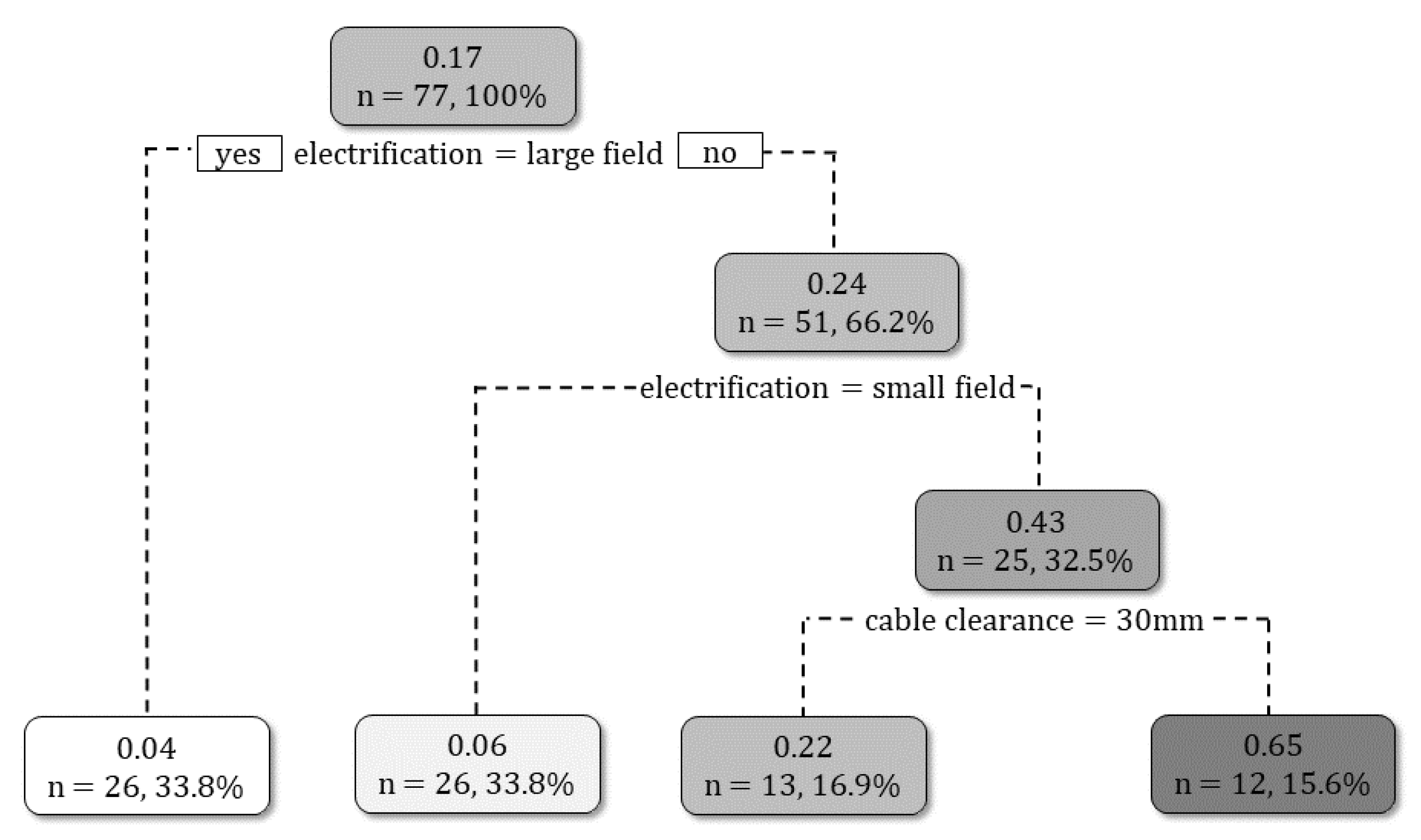
Figure 10.
Decision tree for bypass use per fish showing the importance of the parameters. Following the left branch at a split always means “yes” for the stated parameter value, while following the right branch at a split means “no”. In the boxes, the mean bypass use for per fish is provided as well as the number of experiments and the percentage of all experiments.
Table 1.
Fish species—trout (Salmo trutta fario and Oncorhynchus mykiss), chub (Squalius cephalus), and grayling (Thymallus thymallus)—used in the evaluated ethohydraulic experiments with the total number of available individuals, mean frequency of use per specimen across the 77 experiments, and mean and standard deviation (SD) of fish length.
| Species | Number of Individuals | Mean Frequency of Use per Specimen | Length
Mean ± SD (mm) |
|---|
| Trout | 179 | 6.5 | 187 ± 38 |
| Chub | 226 | 5.1 | 171 ± 38 |
| Grayling | 73 | 11.6 | 257 ± 16 |
Table 2.
The number (#) of independent experiments used for the statistical analysis dependent on the investigated setups: cable clearance (30 mm, 60 mm), electric field (none, small field, large field), and exposition angle (20°, 40°).
Table 2.
The number (#) of independent experiments used for the statistical analysis dependent on the investigated setups: cable clearance (30 mm, 60 mm), electric field (none, small field, large field), and exposition angle (20°, 40°).
| | | # Experiments |
|---|
| Cable Clearance | Electric Field | 20° | 40° |
|---|
| 30 mm | None | 6 | 7 |
| Small Field | 5 | 9 |
| Large Field | 7 | 6 |
| 60 mm | None | 6 | 6 |
| Small Field | 6 | 6 |
| Large Field | 6 | 7 |
Table 3.
For guiding along the Flexible FishProtector per fish, a summary of the coefficient estimates of the gamma regression model with interactions (cf. Equation (1)) is provided.
Table 3.
For guiding along the Flexible FishProtector per fish, a summary of the coefficient estimates of the gamma regression model with interactions (cf. Equation (1)) is provided.
| Parameters | Estimate | Std. Error | z Value | p-Value | Sig. |
|---|
| (intercept) | 0.398 | 0.244 | 1.633 | 0.107 | ns |
| electrification small field | 0.180 | 0.310 | 0.582 | 0.562 | ns |
| electrification large field | −0.508 | 0.315 | −1.613 | 0.111 | ns |
| spacing 60 mm | −1.551 | 0.321 | −4.828 | 0.001 | *** |
| angle 40° | 0.780 | 0.184 | 4.231 | 0.001 | *** |
| spacing 60 mm: electrification small | −1.049 | 0.451 | −2.327 | 0.023 | * |
| spacing 60 mm: electrification large | 0.387 | 0.450 | 0.859 | 0.393 | ns |
| pseudo R2 (sample size) | 0.447 (n = 77) |
Table 4.
For the flight reactions per fish, a summary of the coefficient estimates of the gamma regression model (cf. Equation (1)) without interactions, as they were not statistically significant, is provided.
Table 4.
For the flight reactions per fish, a summary of the coefficient estimates of the gamma regression model (cf. Equation (1)) without interactions, as they were not statistically significant, is provided.
| Parameters | Estimate | Std. Error | z Value | p-Value | Sig. |
|---|
| (Intercept) | −1.099 | 0.209 | −5.249 | 0.001 | *** |
| electrification large field | 0.507 | 0.203 | 2.495 | 0.016 | * |
| spacing 60 mm | −0.220 | 0.203 | −1.085 | 0.283 | ns |
| angle 40° | −0.120 | 0.204 | −0.590 | 0.558 | ns |
| Pseudo R2 (sample size) | 0.138 (n = 52) |
Table 5.
For passing through the Flexible FishProtector per fish, a summary of the coefficient estimates of the gamma regression model with interactions (cf. Equation (1)) is provided.
Table 5.
For passing through the Flexible FishProtector per fish, a summary of the coefficient estimates of the gamma regression model with interactions (cf. Equation (1)) is provided.
| Parameters | Estimate | Std. Error | z Value | p-Value | Sig. |
|---|
| (Intercept) | −1.648 | 0.309 | −5.330 | 0.001 | *** |
| electrification small field | −1.369 | 0.393 | −3.483 | 0.001 | *** |
| electrification large field | −1.601 | 0.400 | −4.006 | 0.001 | *** |
| spacing 60 mm | 1.111 | 0.408 | 2.725 | 0.010 | ** |
| angle 40° | 0.212 | 0.234 | 0.904 | 0.369 | ns |
| spacing 60 mm: electrification small | −1.081 | 0.572 | −1.889 | 0.063 | . |
| spacing 60 mm: electrification large | −1.049 | 0.571 | −1.836 | 0.071 | . |
| Pseudo R2 (sample size) | 0.572 (n = 77) |
Table 6.
For swimming into the bypass per fish, a summary of the coefficient estimates of the gamma regression model (cf. Equation (1)) without interactions, as these were not statistically significant, is provided.
Table 6.
For swimming into the bypass per fish, a summary of the coefficient estimates of the gamma regression model (cf. Equation (1)) without interactions, as these were not statistically significant, is provided.
| Parameters | Estimate | Std. Error | z Value | p-Value | Sig. |
|---|
| (Intercept) | −0.913 | 0.380 | −2.402 | 0.019 | * |
| electrification small field | 0.351 | 0.411 | 0.854 | 0.396 | ns |
| electrification large field | −0.033 | 0.411 | −0.080 | 0.936 | ns |
| spacing 60 mm | −2.087 | 0.335 | −6.227 | 0.001 | *** |
| angle 40° | 1.053 | 0.336 | 3.132 | 0.002 | ** |
| Pseudo R2 (sample size) | 0.287 (n = 77) |


 ,
, 
