Design and Field Monitoring of a Pile–Anchor–Brace Supporting System in a Soft Soil Area
Abstract
:1. Introduction
2. Project Profile
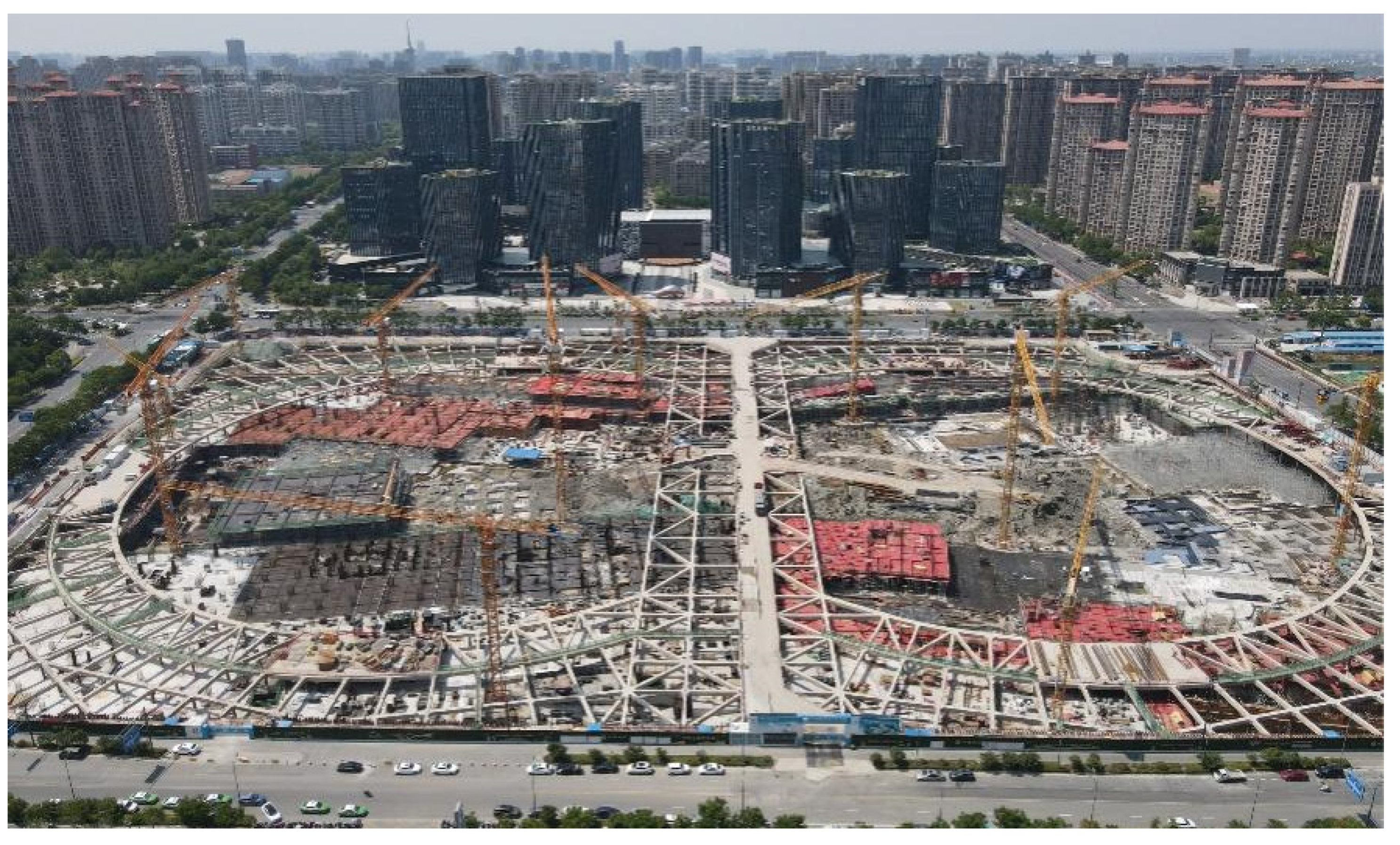
2.1. Site Overview
2.2. Hydrogeological Conditions
3. Design and Construction
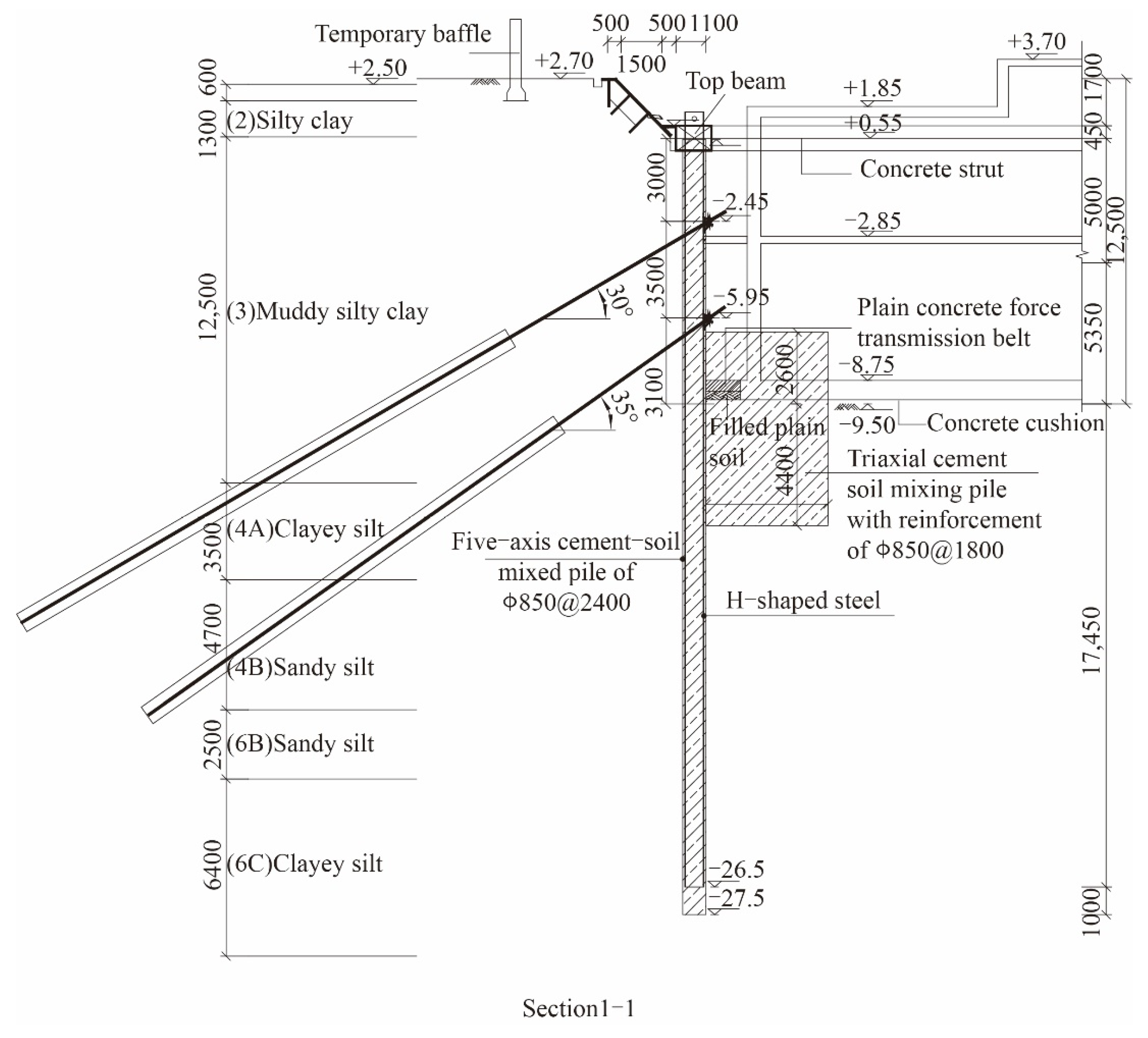
3.1. Selection of Supporting Structure
3.2. SMW Pile
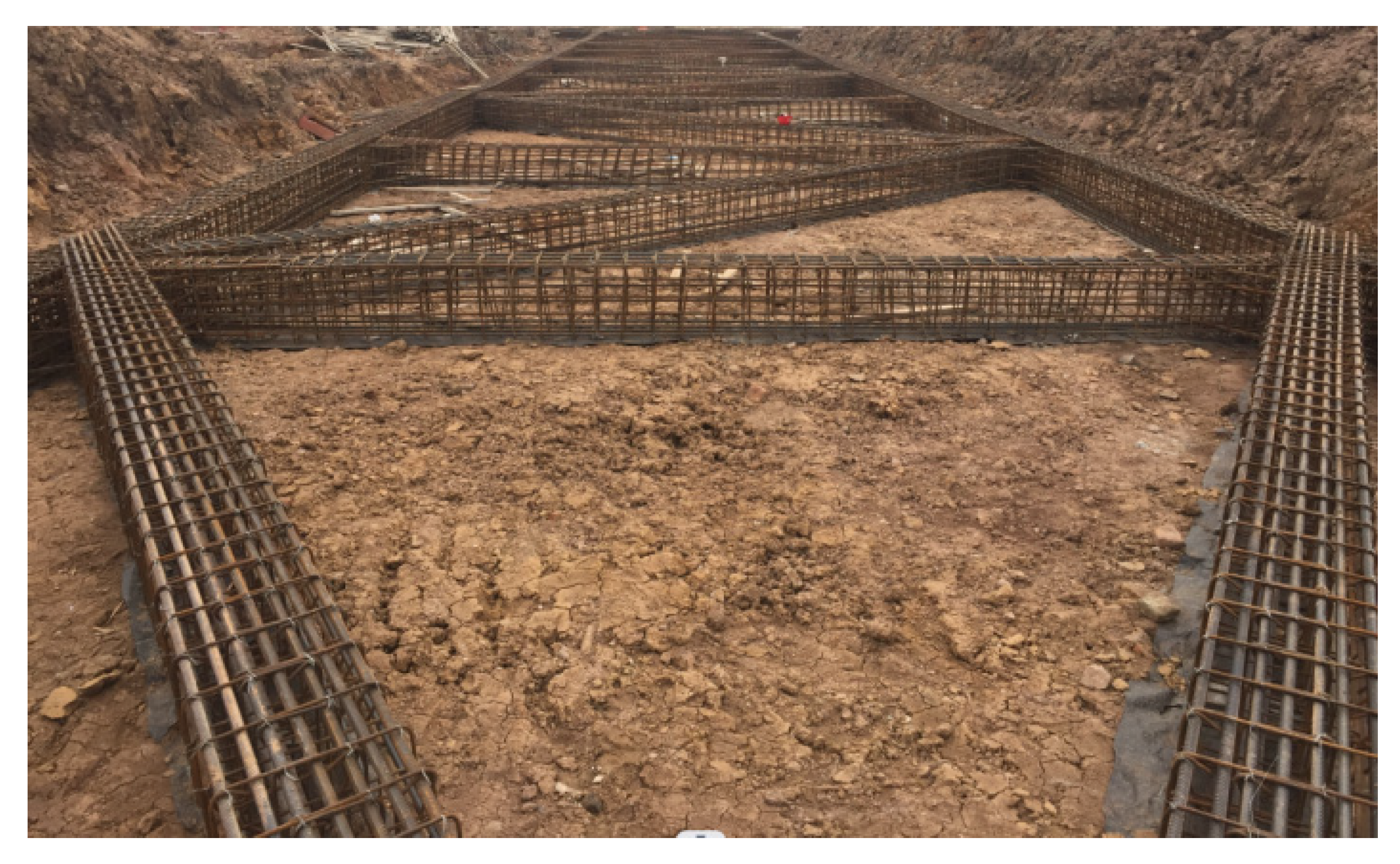
3.3. Concrete Brace
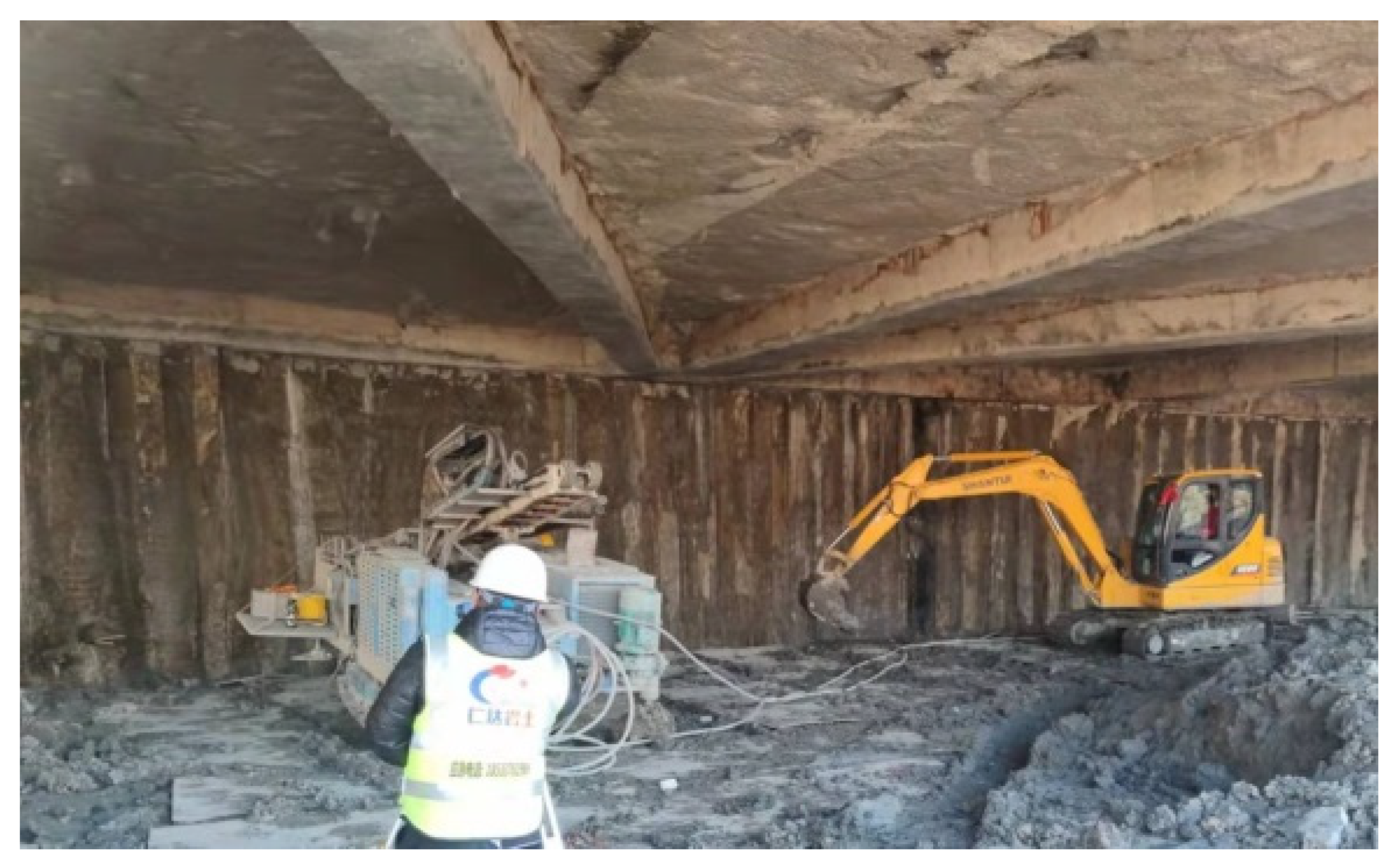
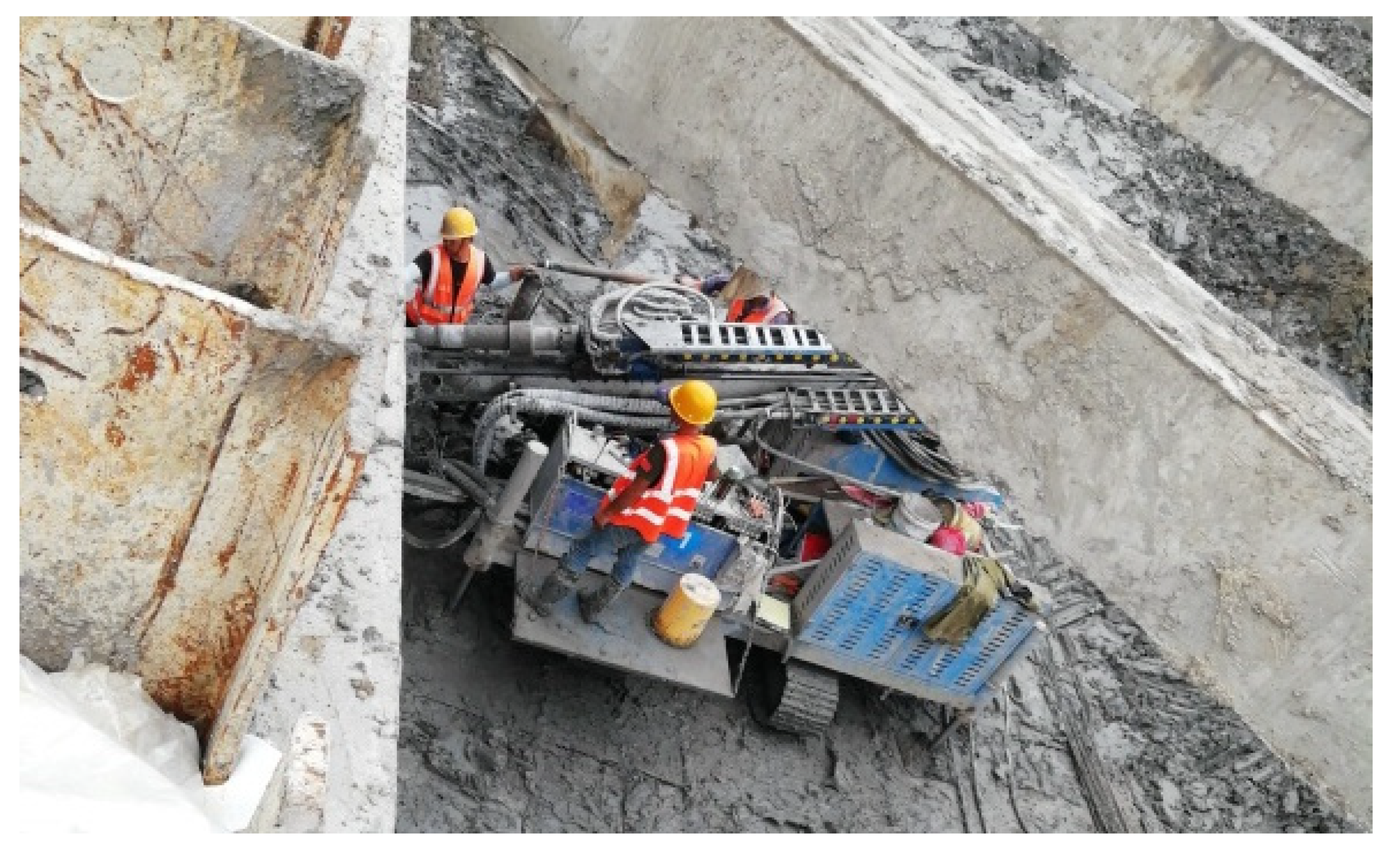
3.4. Rotary Spray Anchor Cable
3.5. Work Conditions
4. On-Site Monitoring and Data Analysis
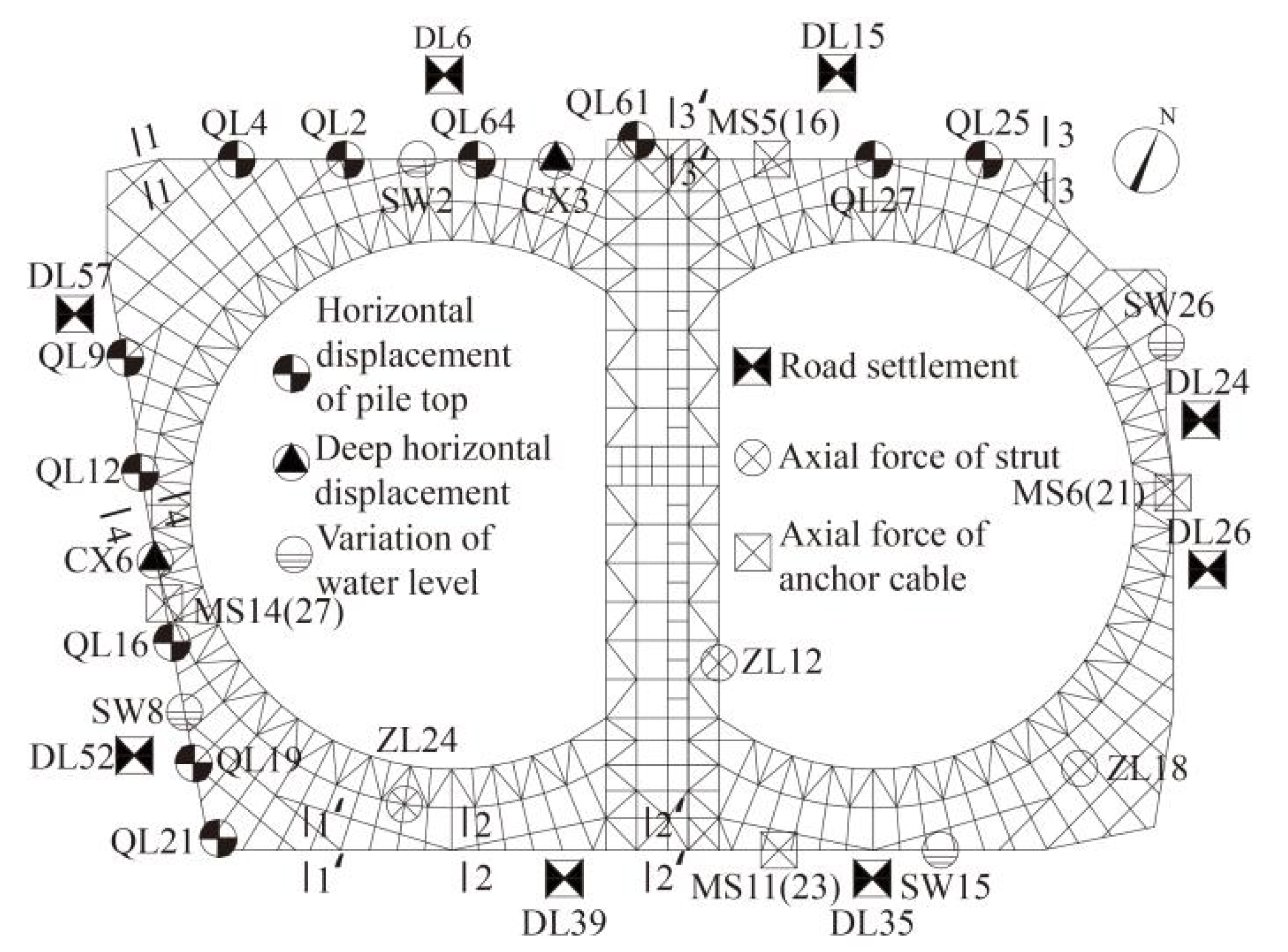
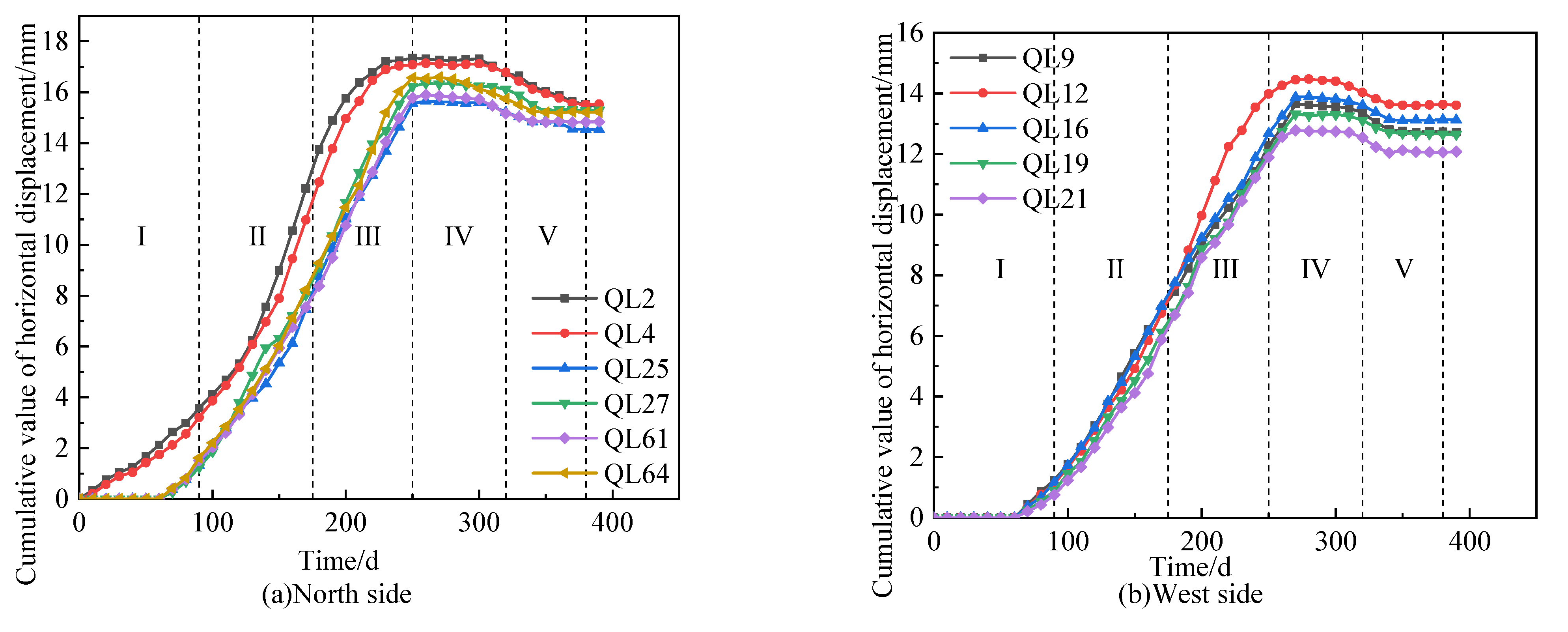
4.1. Horizontal Displacement of the Pile Top
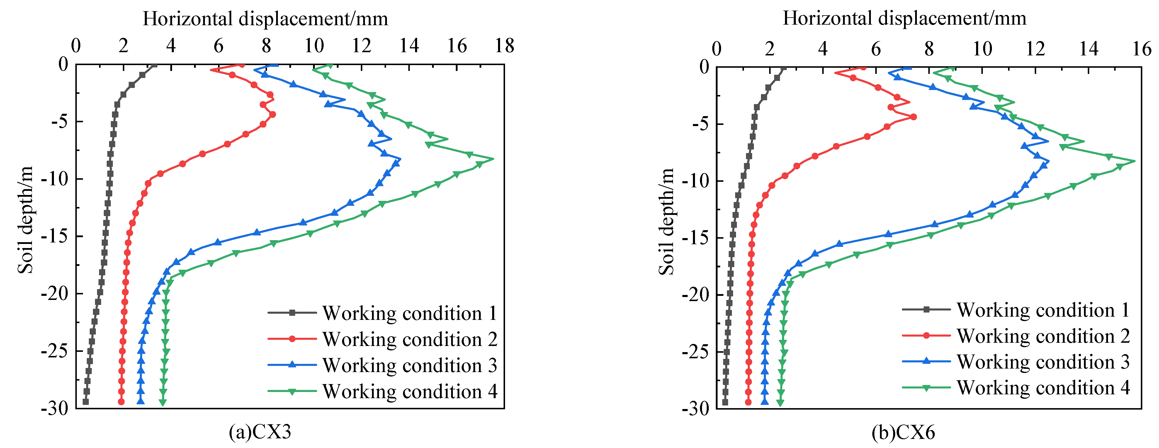
4.2. Deep Horizontal Displacement of the Soil
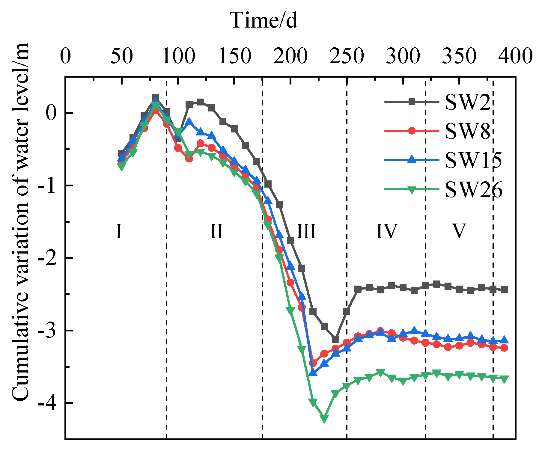
4.3. Groundwater Level Outside the Foundation Pit
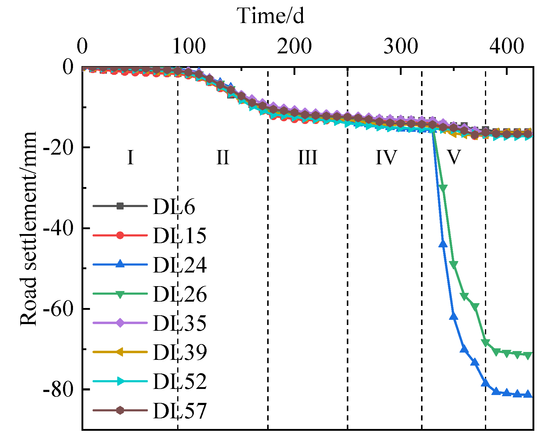
4.4. Road Settlement
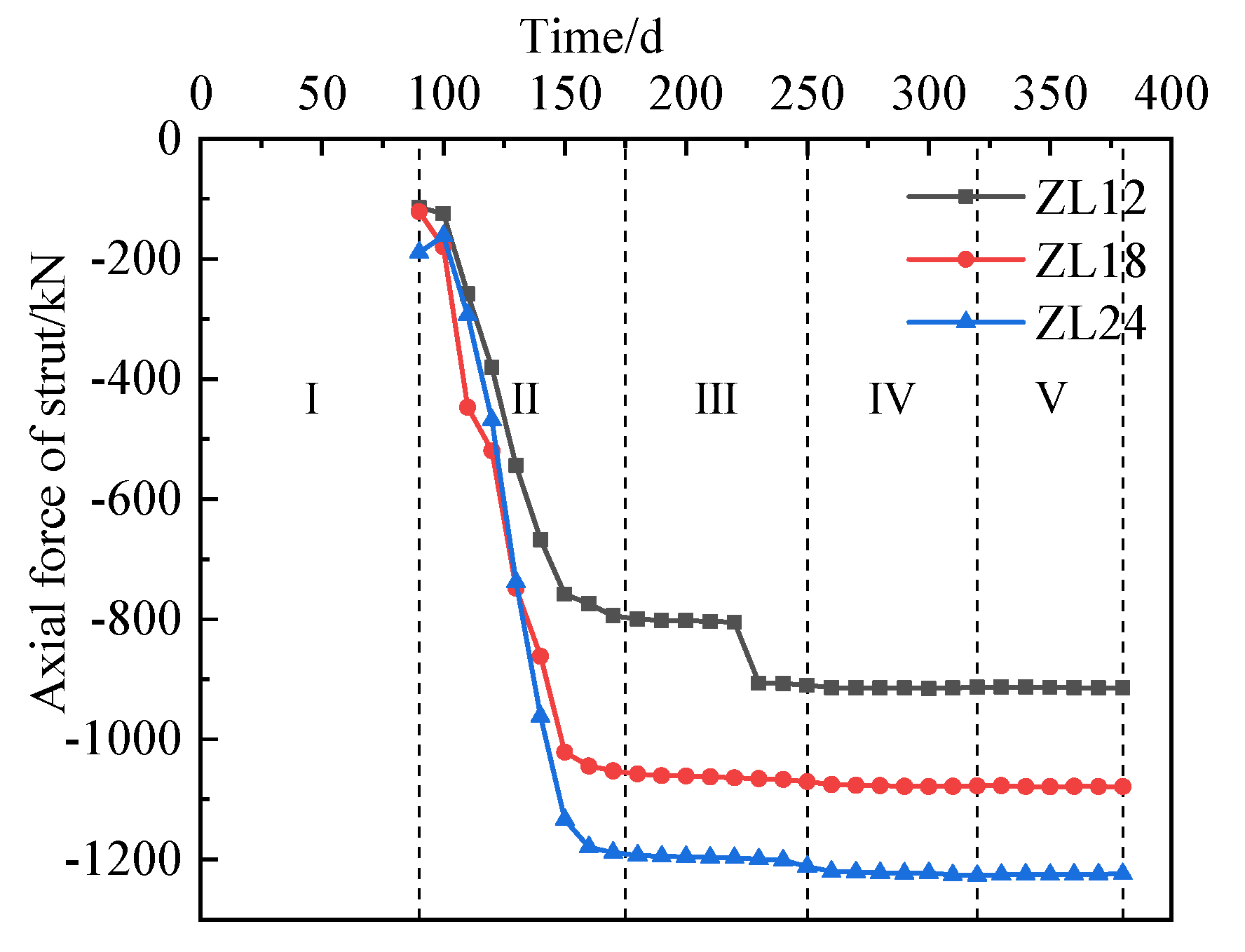
4.5. Axial Force of Brace
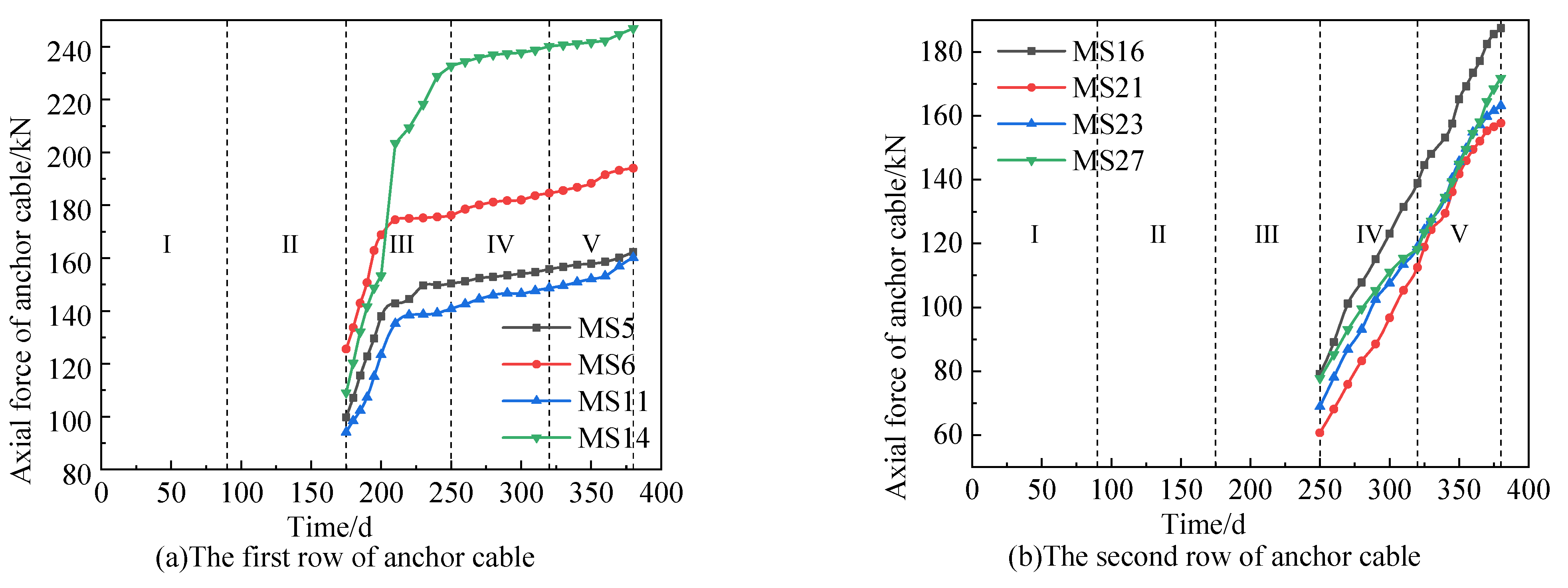
4.6. Axial Force of Anchor Cables
5. Conclusions
- (1)
- The deformation of the foundation pit supported by the pile–anchor–brace supporting system also has an obvious spatial effect. The deformation of the supporting system in the middle of the foundation pit is greater than that in the corner and the deformation of long side of foundation pit is greater than of the short side. Therefore, the deformation monitoring of the supporting system in the middle part of the foundation pit should be strengthened in the process of construction.
- (2)
- The deep horizontal displacement of the soil in the foundation pit supported by the pile–anchor–brace supporting system is initially in the shape of a ‘cantilever’. With the advance of foundation pit excavation, it gradually presents a ’bulge‘ shape. At the position with the inner brace and anchor cable, the horizontal displacement has an obvious sudden change.
- (3)
- The brace axial force would increase rapidly before the construction of anchor cable, but after the completion of the first anchor cable construction, the axial force would gradually become gentle. The axial force of the ring brace is larger than the corner brace, which is larger than the opposite brace.
- (4)
- The change trend of the axial force of the two rows of anchor cables is different. The accumulated axial force of the first anchor cable is large and tends to be gentle after the foundation mat is poured, while the change in the axial force of the second row of anchor cables is relatively gentle. The axial force of the first row of anchor cables is generally greater than the second row. The axial force of the two anchor cables does not exceed their design value, so it can be used as a reference for other projects.
Author Contributions
Funding
Data Availability Statement
Conflicts of Interest
References
- Clough, G.W.; O’Rourke, T.D. Construction induced movements of in situ wall. In Design and Performance of Earth Retaining Structures; Geotechnical Special Publication; American Society of Civil Engineers (ASCE): Reston, VA, USA, 1990; pp. 439–470. [Google Scholar]
- Mana, A.I.; Clough, G.W. Prediction of movement for braced cut in clay. J. Geotech. Eng. Div. 1981, 107, 759–777. [Google Scholar] [CrossRef]
- Ou, C.Y.; Hsieh, P.G.; Chiou, D.C. Characteristics of ground surface settlement during excavation. Can. Geotech. J. 1993, 30, 758–767. [Google Scholar] [CrossRef]
- Hashash, M.A.; Whittle, A.J. Ground movement prediction for deep excavations in soft clay. J. Geotech. Eng. 1996, 122, 474–486. [Google Scholar] [CrossRef]
- Yang, Z.H.; Guo, Z.X. Monitoring analysis of pre-stressed load of anchor cables for deep excavations. Chin. J. Geotech. Eng. 2012, 34, 145–148. [Google Scholar]
- Ju, C.; Li, J.C.; Zhou, X.J. Analysis of foundation pit supporting design and monitoring results in deep saturated soft soil area. Build. Sci. 2012, 28, 107–110. [Google Scholar]
- Xu, W.; Xia, Q.W.; Xu, P.F.; Wang, J.F. Monitoring and analysis of synchronized excavation of extra large-scale adjacent riverside deep foundation pits in soft soil. Chin. J. Rock Mech. Eng. 2013, 32, 2676–2683. [Google Scholar]
- Li, X.L.; Wei, X.; Liang, Z.R. Design practice and analysis of deformation control of deep excavations in soft soil areas. Chin. J. Geotech. Eng. 2014, 36, 160–164. [Google Scholar]
- Zhang, Y.J.; Zeng, J.W. Dynamic monitoring and emergency treatment of deep foundation pit in ultra deep silt layer. Chin. J. Geotech. Eng. 2014, 36, 202–207. [Google Scholar]
- Gong, H.; Xiong, Z.B.; Song, S.H.; Dai, W.K.; Wang, R.J. Structural design and monitoring analysis of deep foundation pit supporting under complex surroundings. Chin. J. Undergr. Space Eng. 2015, 11, 732–738. [Google Scholar]
- Wei, G.; Hua, X.X.; Yu, X.F. Construction monitoring analysis of deep foundation pit excavation of a metro station in Hangzhou. Eng. J. Wuhan Univ. 2016, 49, 917–923. [Google Scholar]
- Li, Y.B.; Dong, W.; Wang, B. Monitoring and analyzing deformation characteristics for deep foundation pit in soft soil area. Bull. Surv. Mapp. 2017, 2017, 116–120. [Google Scholar]
- Li, K.X.; Yang, Z.N.; Li, S.C. Monitoring analysis of deep foundation pit of shield launching section of highway tunnel in soft soil area. Highway 2017, 62, 282–288. [Google Scholar]
- Jiang, J.; Xiao, M.; Liu, Z.Y.; Wang, Z.; Zhang, X.C.; Yang, D. Monitoring of deep foundation pit with a combination of various supporting systems under complicated environment. J. Guangxi Univ. 2018, 43, 269–278. [Google Scholar]
- Long, L.; Li, Z.D. Monitoring and deformation law research of a deep foundation pit project in Changsha. Build. Struct. 2020, 50, 133–137. [Google Scholar]
- Yancheng: Jiangsu Wanda Survey and Detection Design Co., Ltd. Investigation Report of Yancheng First People’s Hospital Phase II and Medical Complex Project; Yancheng Publishing House: Yancheng, China, 2022. [Google Scholar]
- JGJ/T 199-2010; Technical Specification for Soil Mixed Wall. Architecture Press: Beijing, China, 2010.
- Liu, G.B.; Wang, W.D. Manual for Foundation Pit Engineering, 2nd ed.; Architecture Press: Beijing, China, 2009. [Google Scholar]
- GB50010-2010; Code of Design of Concrete Structures. Architecture Press: Beijing, China, 2015.
- China Academy of Building Sciences. Technical Specification for Retaining and Protection of Building Foundation Excavations; Architecture Press: Beijing, China, 2012. [Google Scholar]
- Li, D.P.; Tang, D.G.; Yan, F.G.; Huang, M. Mechanics of deep excavation’s spatial effect and pressure calculation method considering its influence. J. Zhejiang Univ. 2014, 48, 1632–1639. [Google Scholar]

| Soil Layer Sequence | Layer Name | Depth of Soil Layer/m | γ/(kN/m3) | ω/(%) | c’/kPa | φ’/(°) |
|---|---|---|---|---|---|---|
| Layer 1 | Plain fill (Q4m1) | 0.10~1.10 | 17.5 | / | 8.0 | 10.0 |
| Layer 2 | Silty clay (Q4l) | 1.30~2.20 | 18.9 | 29.9 | 20.7 | 8.1 |
| Layer 3 | Muddy silty clay (Q4l) | 12.20~19.20 | 17.3 | 43.7 | 12.5 | 7.1 |
| Layer 4A | Clayey silt (Q4m) | 13.80~19.50 | 18.3 | 32.6 | 14.7 | 14.2 |
| Layer 4B | Sandy silt (Q4m) | 15.00~22.80 | 19.0 | 28.1 | 8.3 | 27.4 |
| Layer 5 | Clayey silt (Q4m) | 18.20~24.10 | 18.3 | 33.3 | 14.8 | 16.8 |
| Layer 6A | Clayey silt (Q4m) | 18.40~24.00 | 18.3 | 32.9 | 13.8 | 17.0 |
| Layer 6B | Sandy silt (Q4m) | 21.70~25.70 | 18.9 | 28.9 | 8.2 | 27.0 |
| Layer 6C | Clayey silt (Q4m) | 24.50~26.00 | 18.4 | 32.1 | 14.9 | 18.0 |
| Type of Brace | Concrete Grade | Sectional Height/mm | Section Width/mm | Reinforcement of Top of Brace | Reinforcement of Bottom of Brace | Longitudinal Stirrup | Lateral Stirrup |
|---|---|---|---|---|---|---|---|
| Opposite brace | C30 | 900 | 800 | 6C25 | 6C25 | C8@200/400 | C8@100/200 |
| Top beam | C30 | 900 | 1300 | 6C20 | 8C20 | 4C8@300 | 4C8@150 |
| Inner ring brace | C30 | 900 | 1400 | 6C20 | 8C20 | 4C8@300 | 4C8@150 |
| Outer ring brace | C30 | 900 | 1300 | 6C20 | 8C20 | 4C8@300 | 4C8@150 |
| Coupling beam | C30 | 900 | 700 | 5C25 | 5C25 | C8@200/400 | C8@100/200 |
| Vertical Position | Dip Angle/(°) | Length of Free Section/m | Anchoring Length/m | Design Value of Axial Force for Anchor Cable/kN | Prestress of Anchor Cable/kN |
|---|---|---|---|---|---|
| First row | 30 | 9 | 23 | 260 | 300 |
| Second row | 35 | 6 | 22 | 205 | 200 |
| Work Condition | Specific Construction Stage | Duration of Experience |
|---|---|---|
| I | Dig the first layer of soil to 3.5 m below the surface and construct the inner brace | 90 d |
| II | Dig the second layer of soil to 6.5 m below the surface and construct the first row of anchor cables | 85 d |
| III | Dig the third layer of soil to 9.5 m below the surface and construct the second row of anchor cables | 75 d |
| IV | Dig the fourth layer of soil to 12 m below the surface and pour the cushion and floor | 70 d |
| V | Construct underground structure to the negative two-layer roof | 60 d |
Publisher’s Note: MDPI stays neutral with regard to jurisdictional claims in published maps and institutional affiliations. |
© 2022 by the authors. Licensee MDPI, Basel, Switzerland. This article is an open access article distributed under the terms and conditions of the Creative Commons Attribution (CC BY) license (https://creativecommons.org/licenses/by/4.0/).
Share and Cite
Sun, L.; Mao, K.; Wang, Z.; Ye, S.; Su, T.; Dai, G.; Xu, G.; Sun, J. Design and Field Monitoring of a Pile–Anchor–Brace Supporting System in a Soft Soil Area. Water 2022, 14, 3949. https://doi.org/10.3390/w14233949
Sun L, Mao K, Wang Z, Ye S, Su T, Dai G, Xu G, Sun J. Design and Field Monitoring of a Pile–Anchor–Brace Supporting System in a Soft Soil Area. Water. 2022; 14(23):3949. https://doi.org/10.3390/w14233949
Chicago/Turabian StyleSun, Lin, Ke Mao, Zhengzhen Wang, Shuaihua Ye, Tiantao Su, Guoliang Dai, Guangxiang Xu, and Jilong Sun. 2022. "Design and Field Monitoring of a Pile–Anchor–Brace Supporting System in a Soft Soil Area" Water 14, no. 23: 3949. https://doi.org/10.3390/w14233949
APA StyleSun, L., Mao, K., Wang, Z., Ye, S., Su, T., Dai, G., Xu, G., & Sun, J. (2022). Design and Field Monitoring of a Pile–Anchor–Brace Supporting System in a Soft Soil Area. Water, 14(23), 3949. https://doi.org/10.3390/w14233949


