1. The Pumped Storage System and Its Constituent Elements
Pumped storage hydro is a mature energy storage method. It uses the characteristics of the gravitational potential energy of water for easy energy storage, with a large energy storage scale, fast adjustment speed, flexible operation and high efficiency [
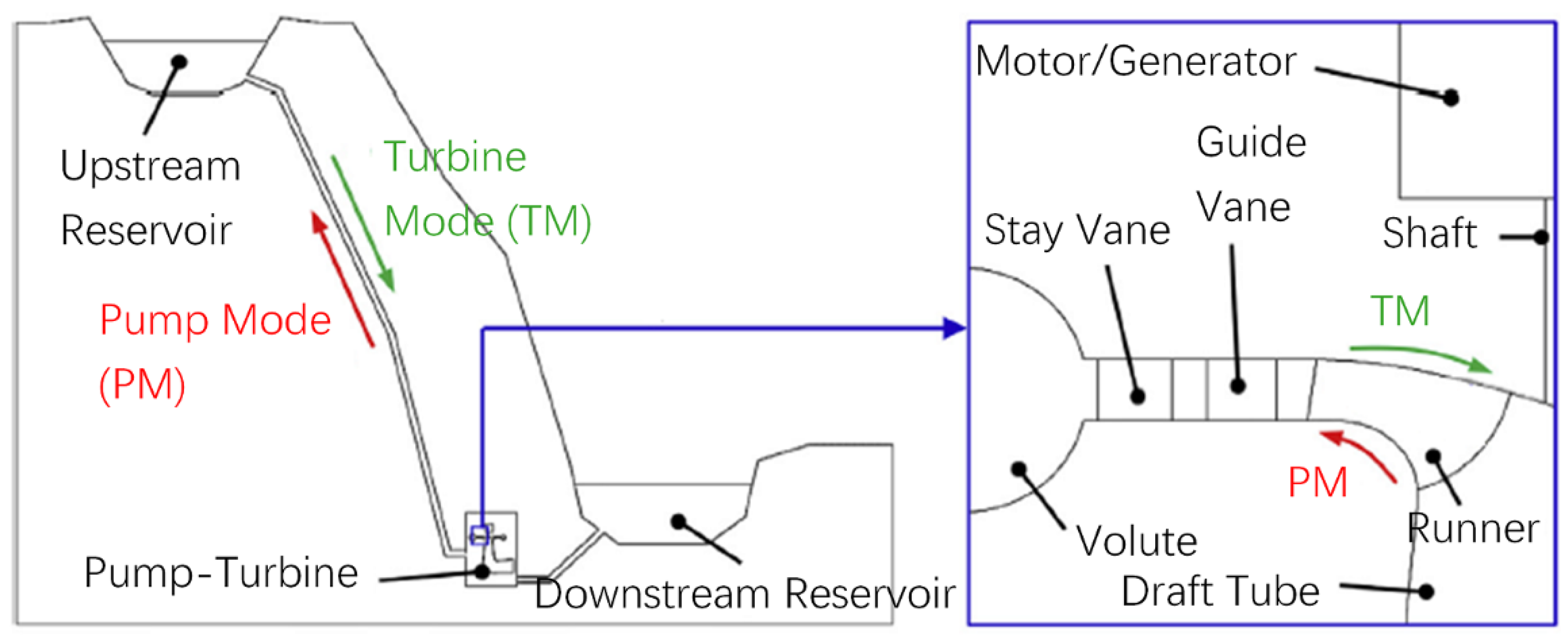
1]. The pumped storage power station, as the equipment for the peak shaving, frequency modulation and phase modulation of the power grid, has been applied in recent decades and can effectively compensate for the instability of the power grid. As shown in
Figure 1, in order to store energy in the form of the mechanical energy of water, an upper reservoir and a lower reservoir are necessary. Penstock is used to connect the two reservoirs. The key components of a pumped storage power station are the hydro turbine and pump, which usually adopt the form of bladed hydraulic machinery. The mechanical energy of the water and the mechanical energy of the runner can be converted to each other. The mechanical energy of the runner depends on the mutual interaction between the generator, or motor, and the electrical energy. In recent years, because of a series of significant advantages, the runners and motors of pumped storage units have come to be designed as reversible [
2,
3]. At the peak level of power consumption during the day, water flows from the lower reservoir into the reservoir. The mechanical energy of the water is converted into the mechanical energy of the runner and then into electrical energy in order to generate electricity. When the power consumption is low at night, the motor drives the runner to rotate, pumping water from the lower reservoir into the upper reservoir for its storage. Pumped storage technology is simple in principle, powerful in function and significant in terms of engineering [
4].
2. Reversibility of Bladed Hydraulic Machinery
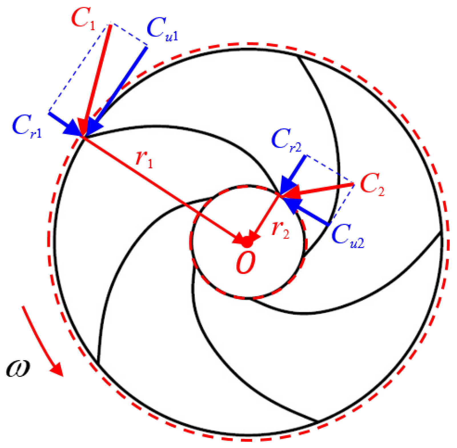
Bladed hydraulic machinery is the foundation of energy conversion in pumped storage technology. According to the theorem of the moment of momentum, the change in the moment of momentum of an axis in unit time is equal to the sum of all the external forces acting on the control body on the same axis. When the external torque is 0, the moment of momentum of the control body remains unchanged. The bladed hydraulic machinery is regarded as the control body (see
Figure 2), and the change in the moment of momentum Δ
L of the fluid can be written as:
where
ρ is the density,
Q is the volumetric flow rate,
r is the radius position of the blade,
Cu is the circumferential component of the absolute velocity
C, and subscripts 1 and 2 represent the runner inlet and outlet. In an ideal state, the energy lost by the water flow is equal to that obtained by the runner:
where
ω is the rotational angular speed of the runner, and
H is the energy difference between the runner inlet and outlet. According to the theorem of the moment of momentum, the change in the moment
M and moment of momentum Δ
L is equal:
If
U represents the linear speed of the runner, we obtain:
As for the relationship between
U and
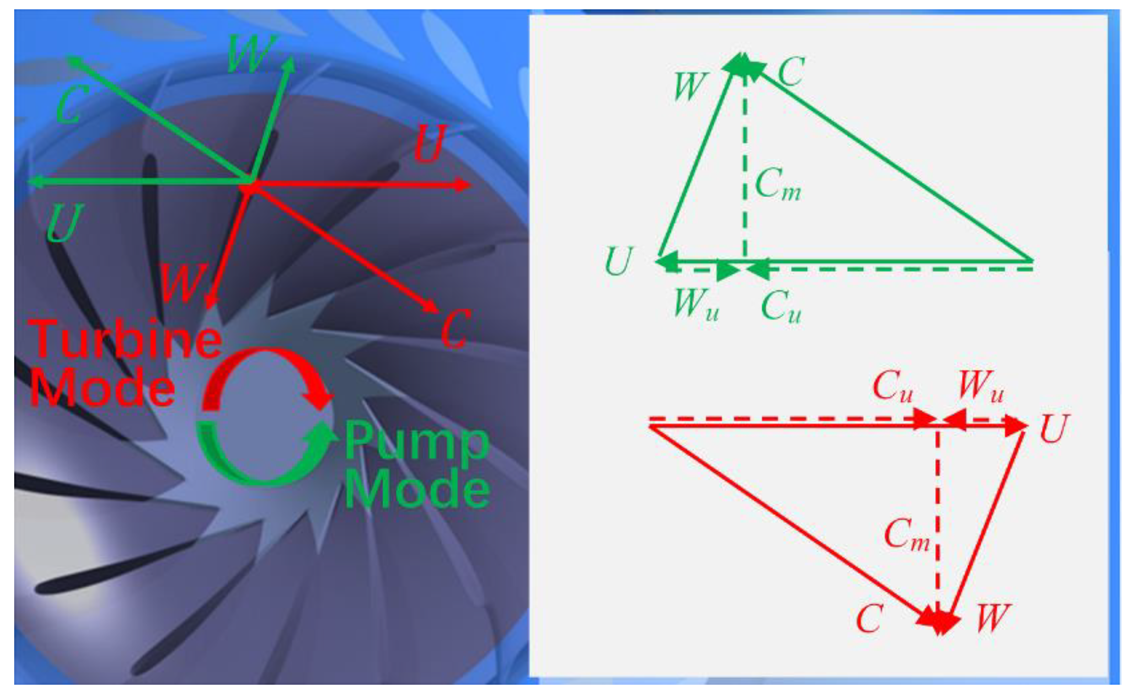
Cu and the relationships between the other velocity components, the velocity triangle shown in
Figure 3 is commonly used in bladed hydraulic machinery [
5]. The relative speed
W is controlled by the blade shape, and the axial speed
Cm is affected by the flow rate. At a certain flow rate, the reasonable design of the blades can cause the runner to convert the ideal energy
H. For a hydro turbine runner whose motor drives it to rotate reversely (the rotational speed is unchanged), the
U magnitude is the same, and the direction is the opposite. The blade shape provides the fluid with the same relative velocity
W in the opposite direction. The resultant absolute velocity
C is the same in terms of the magnitude and opposite in terms of the direction. Components such as
Cu and
Cm also have the same magnitude and reverse direction. According to Equation (5), the fluid obtains energy
H and flows to the upstream reservoir, and the turbomachinery is switched to the pump mode. According to Equations (1) and (2), the momentum moment increases after the fluid flows in and out of the runner. Under ideal conditions, the energy lost by the runner is equal to the energy obtained by the water flow. There are losses under non-ideal conditions, and the runner efficiency in the turbine mode
ηt and pump mode
ηp can be calculated by the following equations:
The reversibility of the bladed hydraulic machinery provides a good solution for the problem of pumped storage technology. One design can be applied to two working modes. The reverse rotation of the runner completes the conversion of the working modes and responds to the demands of the power grid. From an economic perspective, the pumped storage is generally designed with a head of up to 800 m, and the runner is the Francis type [
6]. For the tidal energy, the rising and ebbing tides can be dammed in the bay to realize the forward and reverse pumping and forward and reverse power generation. The low-head
H, full-condition pumped storage hydro units become feasible, similar to the tubular turbine or axial flow pump [
7]. It can also achieve a two-way efficient operation.
3. Cooperation between Pumped Storage and Renewable Energy
China strives to reach peak carbon dioxide emissions by 2030 and achieve the goal of carbon neutrality by 2060. Reducing the use of fossil energy and increasing the proportion of renewable energy are important goals. At present, with the rapid growth of wind power generation and solar power generation, there is a serious problem of instability. Many renewable energy sources, including wind energy, solar energy, tidal energy, wave energy and ocean current energy, require the cooperation with respect to large-scale energy storage technology [
8]. In order to ensure the security and stability of the power system, many countries have built a large number of pumped storage power plants to regulate energy flexibly, efficiently and cleanly. In many developed countries, the proportion of pumped storage power plants in the power system exceeds 10%. At present, the global installed capacity of pumped storage exceeds 160 million kW, accounting for more than 94% of the total energy storage capacity. More than 100 pumped storage projects are under construction, which aim to realize the cooperation with renewable energy demands. High-head, large-capacity, and variable-speed pumped storage units are the focus of subsequent development and construction. The study of the flow problems of vane-type hydraulic machinery pumps and turbines is of great significance for the stable operation of pumped storage units. In particular, in the development of pumped storage technology, this is very important for efforts to clarify the
Q-H stability characteristics, start-up
S-characteristics, inception cavitation, pressure pulsation and other issues.


