Article

Analysis of Energy Characteristics and Internal Flow Field of “S” Shaped Airfoil Bidirectional Axial Flow Pump

1
College of Engineering, Anhui Agricultural University, Hefei 230036, China
2
College of Hydraulic Science and Engineering, Yangzhou University, Yangzhou 214000, China
*
Author to whom correspondence should be addressed.
Water 2022, 14(18), 2839; https://doi.org/10.3390/w14182839
Submission received: 8 August 2022 / Revised: 8 September 2022 / Accepted: 9 September 2022 / Published: 12 September 2022
(This article belongs to the Special Issue Advancement in the Fluid Dynamics Research of Reversible Pump-Turbine)

Abstract

:
In order to study the energy characteristics and internal flow field of “S” shaped airfoil bidirectional axial flow pumps, the SST k-ω turbulence model is used to calculate the bidirectional axial flow pump, and the experimental verification is carried out. The results show that the error of numerical calculation of forward and reverse operation is within 5%, and the numerical calculation result is credible. The test results show that the bidirectional axial flow pump has a design flow rate of Q = 368 L/s, head H = 3.767 m, and an efficiency of η = 80.37%. In reverse operation, the flow of the bidirectional axial flow pump under design condition Q = 316 L/s, head H = 3.658 m, efficiency η = 70.37%. The flow of forward operation is about 15% larger than that of reverse operation under design working condition, the design head is about 3.70 m, and the efficiency of design working condition is about 10% higher than that of reverse operation. The numerical calculation results show that under the forward design condition (Q = 368 L/s), the hydraulic loss accounts for 6.22%, and under the reverse design condition (Q = 316 L/s), the hydraulic loss accounts for 11.81%, with a difference of about 6%. The uniformity of impeller inlet flow rate under the forward operation is about 12% higher than that in the reverse operation. In forward and reverse operation, with the increase of flow, the outlet streamline, the outlet total pressure distribution, the uniformity of impeller inlet velocity, and the vortex in the impeller domain are improved, and the forward direction is better than the reverse direction. The research results of this paper can provide a reference for the research and optimal design of the bidirectional axial flow pump.

1. Introduction

The water transfer project is a project to improve the people’s basic livelihood, playing an increasingly important role in the irrigation of river, coastal, and plain areas. Flood control and drainage standards are also constantly improving, increasing the demand for pumping stations to achieve dual-use irrigation and drainage, and positive and negative performance balance. At present, most of the pumping stations utilize the unidirectional axial flow pump reversing motor operation or switch the river and pumping station flow channel to achieve bidirectional operation. In the former, forward operation of the maximum efficiency of the pump can reach about 85%, and reverse operation because of the vane is a reverse arch state and poor inlet water flow pattern. The flow, head, and efficiency of the pump are greatly weakened, with the maximum efficiency of only 65% or less, showing deviation from national energy-saving and emission reduction targets. Regarding the latter, although the pumping station can realize bidirectional operation and the same performance of forward and reverse operation, the highest efficiency of forward and reverse direction is only about 72%, and the flow channel and river channel are switched. In turn, the civil construction cost is large, which increases the cost of operation and management and maintenance. In response to these problems, the relevant scholars, through the improvement of the axial flow pump and its impeller, support the use of a symmetrical form of wing design bidirectional axial flow pump, in the design method to make innovation. In the development of a new bidirectional axial flow pump impeller, the impeller alone, its forward and reverse performance is superior. At present, the symmetrical wing type has a flat wing type, the center line of the wing type is a straight line, another is “S” shaped airfoil, the center line of the airfoil is “S” shaped. The flat airfoil type bidirectional axial flow pump forward operating efficiency is about 5% worse than the conventional unidirectional axial flow pump forward operating, while reverse operating efficiency is about 15% worse than the conventional unidirectional axial flow pump forward operating, “S” shaped airfoil type bidirectional axial flow pump forward operating efficiency is about 2% worse than the conventional unidirectional axial flow pump forward operating, and reverse operating efficiency is about 10% worse than the conventional unidirectional axial flow pump forward operating. Because of its excellent forward and reverse performance, it has been paid attention to and applied. However, the research on “S” shaped bidirectional axial flow pump is less, and its energy characteristics and internal flow mechanism are not clear, which leads to the lack of theoretical guidance for the design and operation of “S” shaped bidirectional axial flow pumps.
Relevant scholars proposed to use “S” shaped airfoil to design bidirectional axial flow pump [1]. Some scholars have explored the internal flow field of the bidirectional axial flow pump, including the pressure fluctuation characteristics in both forward and reverse directions of the bidirectional axial flow pump [2], the generation mechanism of the vortex in the impeller [3], and the internal flow characteristics of the “S” shaped airfoil bidirectional axial flow pump under cavitation [4], and some scholars have optimized the design of bidirectional axial flow pump or pump device, including reducing the chord length and number of blades and appropriately increasing the axial spacing to enhance the performance of bidirectional axial flow pump [5], investigating the effect of guide vane position on the hydraulic performance and flow pattern of bidirectional vertical shaft cross-flow pump [6], investigating the effect of lobe root clearance on the hydraulic performance of bidirectional axial flow pump [7], and changing the ratio of radius of the centerline circle of S-shaped bend of bidirectional pump to the optimized design of the shaft extension cross-flow pump device of “S” shaped two-way axial flow pump [8]. The influence of different placement positions of the vertical shaft on the performance of the vertical shaft cross-flow pump of “S” shaped two-way axial flow pump was investigated [9]. Some scholars have also studied the flyaway conditions of bidirectional horizontal axial flow pumps operating in forward and reverse directions and concluded that the magnitude of pulsation of axial force in forward operation is significantly larger than that in reverse [10].
The “S” shaped airfoil bidirectional axial flow pump has the advantages of simple structure, convenient installation, easy operation, maintenance, and management, and it has been widely used. In the process of application, relevant scholars have carried out some optimization design work on it or its pump device, but the research on its energy characteristics and internal flow mechanism is less involved, and related studies are also not deep enough. This paper takes the “S” shaped airfoil bidirectional axial flow pump as the research object to explore its energy characteristics and internal flow characteristics during forward and reverse operation, in order to ensure the safe, stable, and efficient operation of the bidirectional axial flow pumping station.

2. Numerical Computation Models, Grids and Computational Methods

2.1. Numerical Calculation Models

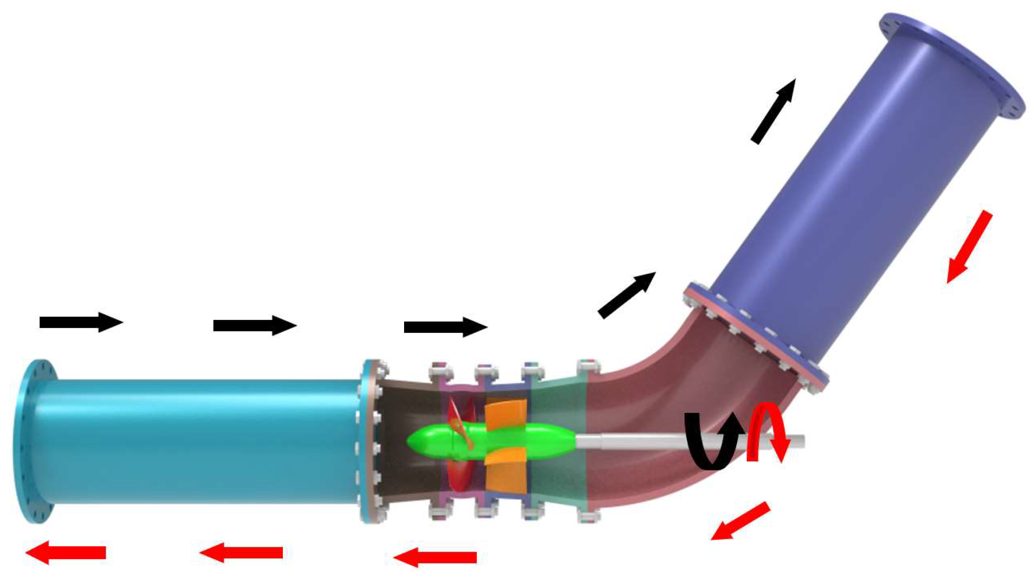
The “S” shaped bidirectional axial flow pump is designed by the “S” shaped airfoil, and its geometric structure includes: inlet pipe, impeller, guide vane and outlet pipe, where the number of impeller blades is 4, impeller diameter D is (300–0.2) mm, and the number of guide vane blades is 5. The parameters of the “S” shaped bidirectional axial flow pump are shown in Table 1, the “S” shaped 3D model is shown in Figure 1, and the “S” shaped bidirectional axial flow pump impeller 3D model is shown in Figure 2. The forward and reverse operation of the “S” shaped bidirectional axial flow pump is shown in Figure 3.
As shown in Figure 3, when the bidirectional axial flow pump is in forward operation, the water enters from the side of the inlet pipe and passes through the impeller to lift the energy. Then, the guide vane rectifies the flow, enters the outlet elbow, and then flows out in an oblique 60° direction. In reverse operation, the water enters from the elbow side, flows through the guide vane first, then passes through the impeller to raise energy, and finally flows out of the horizontal straight pipe. In forward and reverse operation, the impeller rotates in the opposite direction.

2.2. Meshing

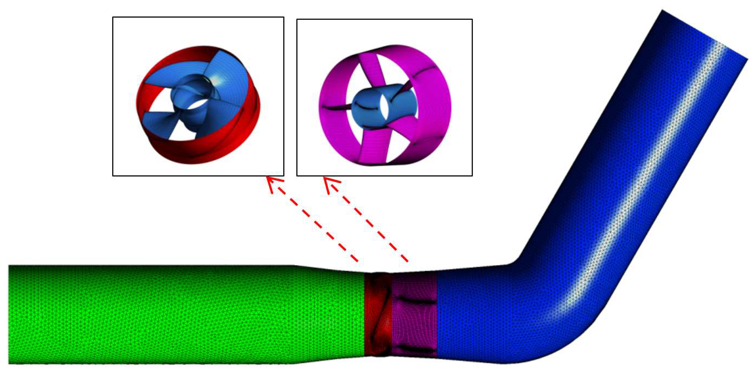
The fluid inside the inlet and outlet pipes is extracted, the inlet and outlet pipes are divided into unstructured meshes in ANSYS ICEM software, and the boundary layer is locally encrypted considering the thickness of the boundary layer (the change rate of the mesh from the boundary to the interior is 1.05). The impeller and guide vane body are modeled and the structured mesh is divided using ANSYS Turbo Grid software, and the boundary layer and local features of each computational domain are encrypted when the mesh is divided. The impeller adopts “J” topology and guide vane adopts “O” topology. The impeller and guide vane y+ (y+ is a dimensionless quantity of distance from the wall, which is proportional to the height of the first grid layer of the wall. In the numerical calculation using SST k-ω and RNG k-ε turbulence models, the rotational and shear flow y+ is taken as 30~100) values are all around 50, and the impeller top clearance adopts the "H" topology and arranges a 7-layer grid, with y+ values around 10 and grid masses greater than 0.35. The overall grid of the computational model is shown in Figure 4, and the grid irrelevance analysis is shown in Table 2.
As shown in Table 2, when the number of grids reaches 2,678,813, the number of grids has basically no effect on the calculation results. Considering the computing power of the computer, grid Serial Number scheme 3 is selected for the subsequent numerical calculation work in this paper.

2.3. Control Equations, Boundary Conditions and Calculation Methods

In this paper, the SST k-ω turbulence model is used to numerically calculate the bidirectional axial flow pump in CFX software. The rated speed of the impeller is set to be −1450 r/min when the bidirectional axial flow pump operates in the forward direction, and 1450 r/min when the impeller operates in the reverse direction. The inlet is set to be the Mass Flow Inlet, the outlet is set to be the Average Static Pressure Outlet, the pressure is set to be 0.2 atm, the Non Moving Wall surface of the solid is set to be the Static Wall Surface, the Non Slip condition is applied, and the boundary condition of the standard wall function is used in the Near Wall Area. The “Stage” interface method is adopted for the dynamic and static interface. The finite volume method based on the finite element is used for discretization of the governing equation, the diffusion term, and pressure gradient are expressed by the finite element function, and the convection term is expressed by the High Resolution Scheme. The convergence condition of each parameter of the flow field is set to 10−6. In principle, the smaller the residual value, the better.

2.4. Analytical Formulae for Numerical Calculation Results

The numerical calculation head Hnet calculation formula is [11,12,13]:
H n e t = ( S 2 p 2 u t 2 d S ρ Q g + H 2 + S 2 u 2 2 u t 2 d S 2 Q g ) ( S 1 p 1 u t 1 d S ρ Q g + H 1 + S 1 u 1 2 u t 1 d S 2 Q g )
The numerical calculation efficiency η calculation formula is [14,15]:
η = ρ g Q H n e t T ω × 100 % ,
where: P1 and P2 are the average static pressure (Pa) at the inlet and outlet of the axial flow pump channel; ρ is the flow density (kg/m3); g is the acceleration of gravity (m/s2); s1 and s2 are the cross section areas of inlet and outlet of axial flow pump (m2); u1 and u2 are the flow velocity at each point of the inlet and outlet channel section of the axial flow pump (m/s); ut1 and ut2 are the normal components of flow velocity at each point of the inlet and outlet channel section of axial flow pump (m/s); Q is axial flow pump flow (m3/s); T is the rotating torque of impeller (N·m); ω is the impeller rotation angle speed (rad/s).

3. Test Device and Test Method

3.1. Test Device

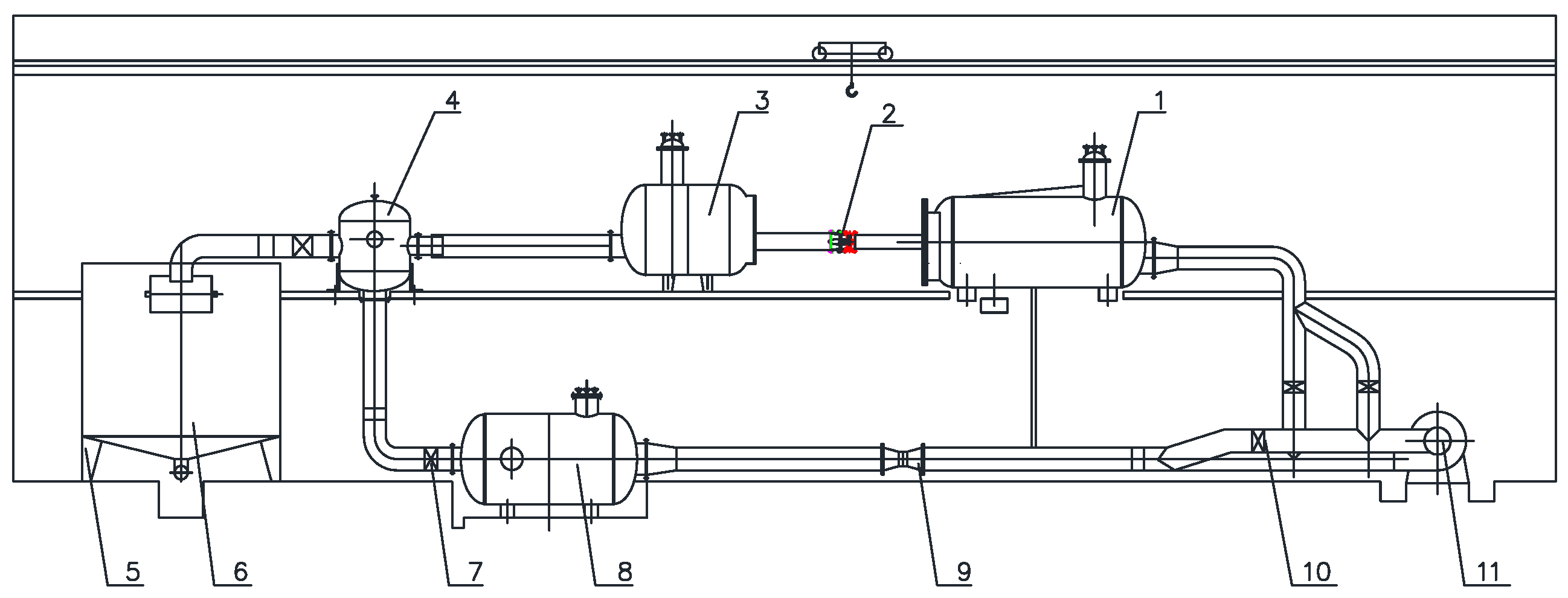
The test bench is a vertical closed cycle system, as shown in Figure 5.
In the test, the head is measured using the differential pressure transmitter (accuracy ± 0.015%), the flow is measured by electromagnetic flowmeter (accuracy ± 0.18%), the speed and torque are measured by speed torque sensor (accuracy ± 0.24%), the NPSH is measured by absolute pressure transmitter (accuracy ± 0.015%), and the comprehensive uncertainty of the test bench is ±0.39%.

3.2. Test Method

The head H of the test pump is calculated by the following formula [16]:
H = ( p 2 ρ g p 1 ρ g + z 2 z 1 ) + ( u 2 2 2 g u 1 2 2 g ) ,
The test shaft power N is calculated by the following formula [17]:
N = π 30 n ( M M ) ,
Test pump efficiency η calculated by the following formula [18]:
η = ρ g Q H N × 100 % ,
where H is the pump head (m), P1 and P2 are the static pressure (Pa) at the inlet and outlet of the flow field, z1 and z2 are the height (m) of the inlet and outlet of the flow field, u1 and u2 are the flow velocity (m/s) at the inlet and outlet of the flow field, ρ is the real-time water density of the test (kg/m3), g is the local gravity acceleration (m/s2), N is the shaft power (kw), M is the pump input torque (N·m), M′ is the pump mechanical loss torque (N·m), n is the pump test speed (r/min), η is the pump model efficiency (%), and Q is the pump flow (m3/s).

4. Numerical Calculation Results and Experimental Verification

4.1. Experimental Verification of Numerical Calculation Energy Characteristics

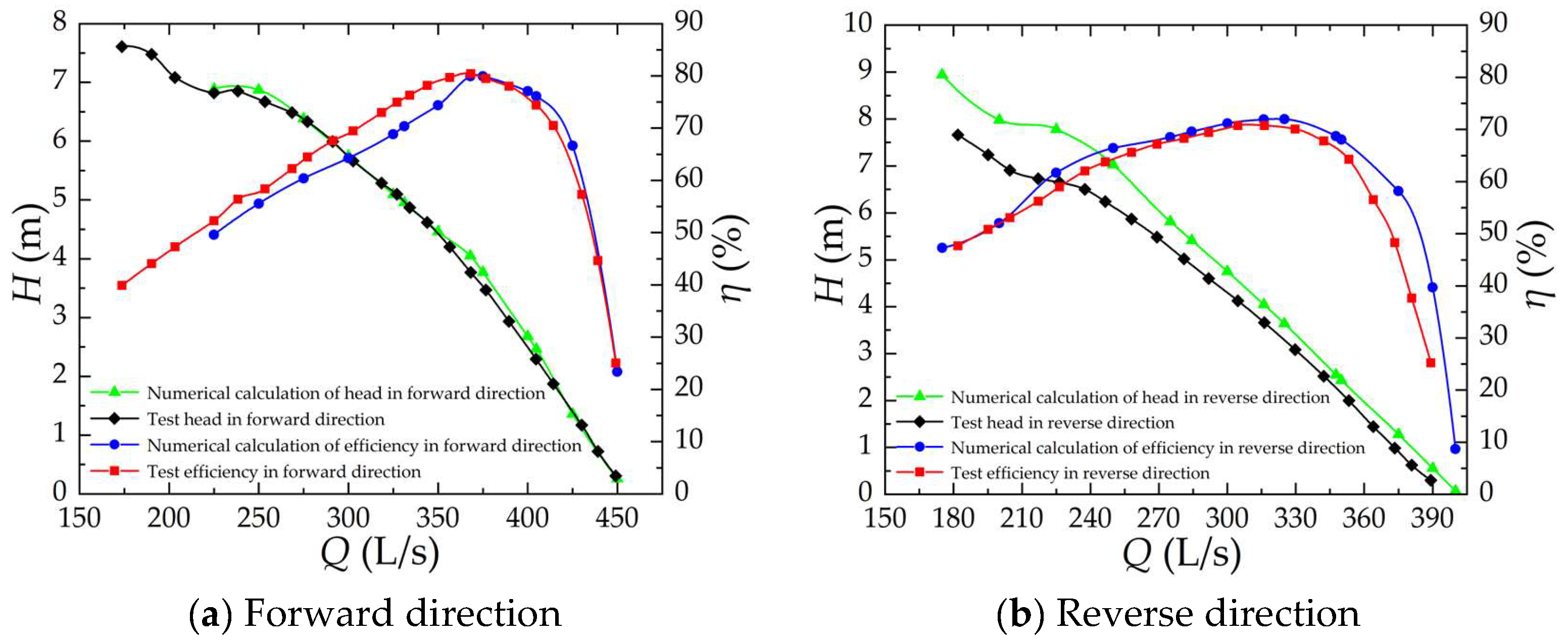
The comparison between the forward and reverse numerical calculation and the experimental energy characteristic curve of the “S” shaped airfoil bidirectional axial flow pump is shown in Figure 6.
By comparing and analyzing the test results in Figure 6, it can be concluded that the Q = 368 L/s, H = 3.767 m, and efficiency of the bidirectional axial flow pump under the design condition of forward operation η = 80.37%, whereas in reverse operation, the flow of bidirectional axial flow pump under design condition Q = 316 L/s, H = 3.658 m, η = 70.37%. The flow of forward operation is about 15% higher than that of reverse operation under the design condition, but the difference in head is small, both of which are about 3.70 m in the design head, and the efficiency of design condition is about 10% higher in the forward direction than in the reverse direction. The main reason why the forward operation performance is better than the reverse operation is that the flow velocity uniformity at the inlet of the forward operation impeller is higher than that in the reverse operation, and the forward water inflow condition is better. The reverse operation has poor water inflow condition due to the front guide vane at the inlet of the impeller.
By comparing and analyzing Figure 6, we can observe that the prediction of forward numerical calculation of bidirectional axial flow pump is more accurate, and the error is basically within 3%, while the prediction accuracy of reverse numerical calculation is slightly worse, and the error is basically within 5%, which means that the numerical calculation accuracy is higher and the calculation results are credible. It can also be found from the figure that the prediction accuracy of the forward numerical calculation of the bidirectional axial flow pump is better than the reverse, which is mainly because the internal flow characteristics of the bidirectional axial flow pump are complicated during reverse operation, so the prediction accuracy is slightly worse.

4.2. Numerical Calculation and Energy Characteristic Analysis

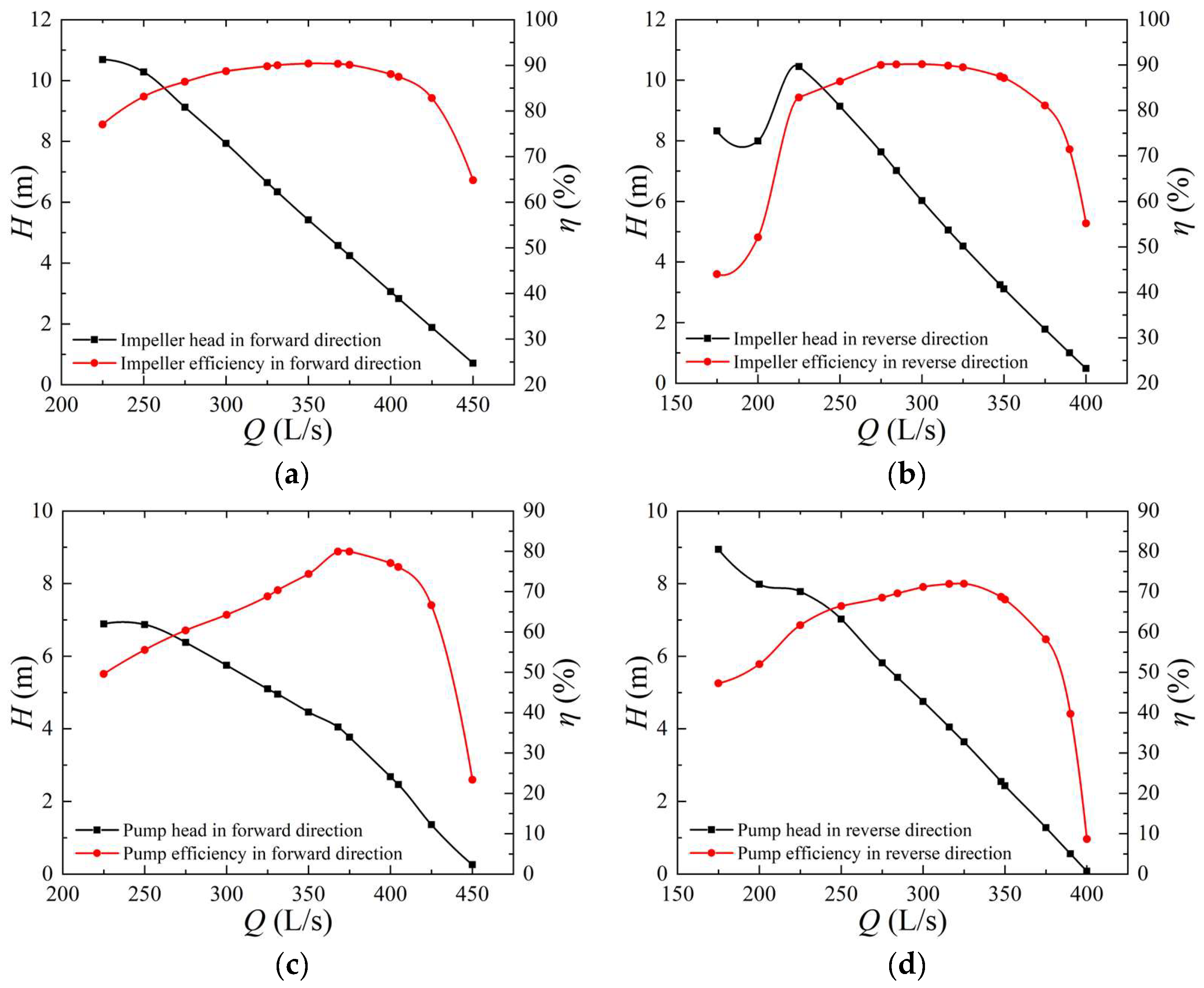
According to the numerical calculation results, the energy characteristic curves of the bidirectional axial flow pump impeller in the forward and reverse directions are organized by Equations (1) and (2), as shown in Figure 7a,b, and the energy characteristics of the bidirectional axial flow pump in the forward and reverse directions are organized as shown in Figure 7c,d.
It can be obtained from the numerical calculation that the design working flow rate of the impeller in forward operation is Q = 368 L/s, head H = 4.575 m, efficiency η = 90.32%, and the design working flow rate of the impeller in reverse operation is Q = 316 L/s, head H = 5.055 m, efficiency η = 89.87%. The “S” shaped bidirectional airfoil is completely symmetrical in both forward and reverse directions, and the impeller designed by it is also completely symmetrical in both forward and reverse directions with the same performance, so the difference between the optimal efficiency of the impeller in forward and reverse directions is not large. However, the increase of the guide vane and elbow and other flow guide structure not only makes the “S” shaped airfoil bidirectional axial flow pump optimal operating point shift, and the flow-head to produce differences also larger, but the forward operation of the head under the same flow is significantly greater than the reverse, mainly because the impeller inlet water impulse angle is different, causing the forward operation of the impeller inlet absolute liquid flow angle to be significantly greater than the reverse operation of the impeller inlet absolute liquid flow angle.
Forward operation bidirectional axial flow pump design condition flow rate Q = 368 L/s, head H = 4.049 m, efficiency η = 79.93%, and reverse operation bidirectional axial flow pump design condition flow rate Q = 316 L/s, head H = 4.045 m, efficiency η = 71.91%. By comparing the numerical calculation results, it can be seen that the forward and reverse high flow conditions performance difference is large and forward design condition point efficiency is 8% larger than the reverse. Under the same flow, forward head is equivalent to the reverse vane angle increased by about 2° of head.
There are structural differences between the two directions of operation of the bidirectional axial flow pump. The front of the impeller in forward operation is a straight tube, the impeller outlet is a guide vane and elbow, the reverse operation of the impeller inlet is elbow and guide vane, and the outlet is a straight tube. These structural characteristics of the differences lead to hydraulic losses of the inlet and outlet pipes and guide vane. The flow velocity uniformity and the water impulse angle of the impeller inlet are all different, so the difference between the forward and reverse performance is large.
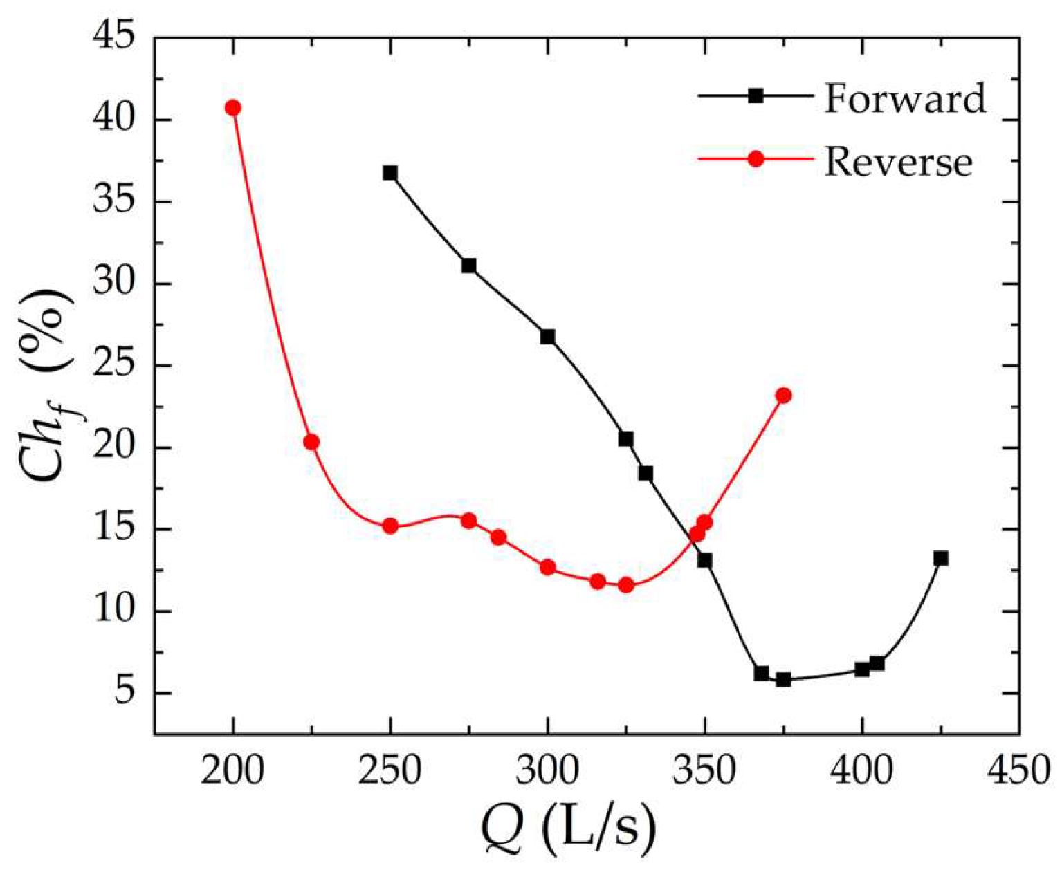
In this paper, the hydraulic loss ratio is defined as the ratio of the sum of the total hydraulic loss of the inlet pipe, outlet pipe, and guide vane in comparison with the head of the bidirectional axial flow pump, and the hydraulic loss ratio is calculated by the following equation:
C h f = h i + h g + h o H ,
where Chf is the hydraulic loss ratio, hi is the inlet pipe hydraulic loss (m); hg is the guide vane body hydraulic loss (m); ho is the outlet pipe hydraulic loss (m); H is the pump head (m).
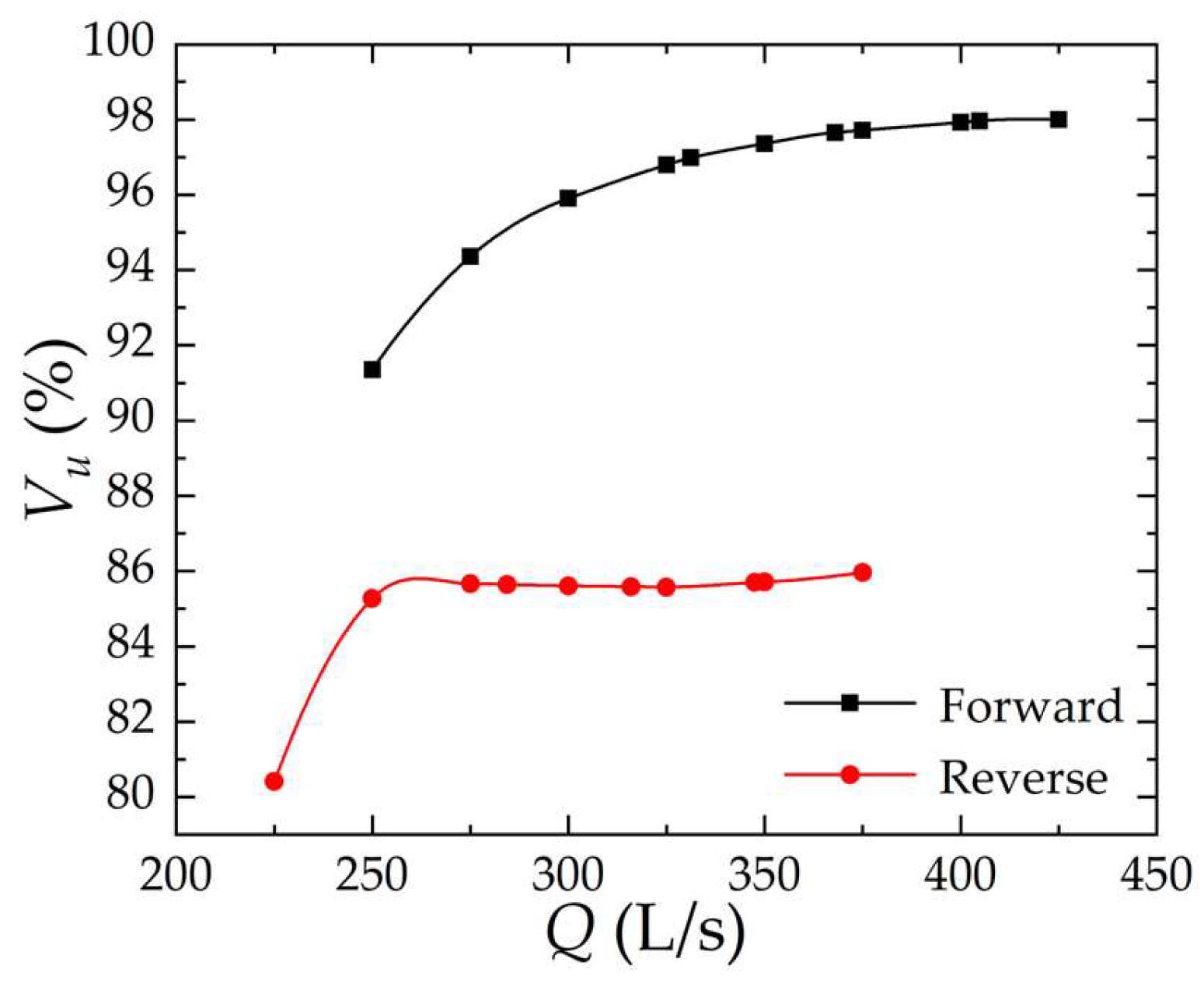
The equation for the inlet flow velocity distribution uniformity of the impeller is [19]:
V u = { 1 1 v a ¯ [ i = 1 n ( v a i ν a ¯ ) 2 ] / n } × 100 % ,
where Vu is the uniformity of axial flow velocity distribution in the characteristic section (%); vai is the axial velocity of each calculation unit (m/s); n is the number of calculation units. va is the axial flow velocity at impeller inlet.
Forward and reverse operation bidirectional axial flow pump inlet and outlet pipes and guide vane hydraulic loss are shown in Figure 8. The impeller inlet flow rate uniformity is shown in Figure 9.
Through Figure 8 and Figure 9, it can be concluded that the, considering forward design condition (Q = 368 L/s), the hydraulic loss percentage in the peak and valley region, the value is close to the minimum 6.22%, and considering the reverse design condition (Q = 316 L/s), the hydraulic loss percentage is also in the peak and valley region. The value is close to the minimum 11.81%, with a difference of about 6%, and this leads to the reverse design condition efficiency being lower than the forward 6%. The efficiency of the forward design working point is 8% larger than that of the reverse, and the other 2% difference is mainly due to the fact that the inlet flow velocity uniformity of the impeller in the forward operation is about 12% higher than that of the reverse, resulting in a difference of about 2% in the forward and reverse efficiency. The main reason for the different hydraulic loss and flow velocity uniformity in forward and reverse operation is that in reverse operation, the curved guide vane is front-loaded, which reduces the flow velocity uniformity of the impeller inlet, resulting in an increase in the bad flow pattern of the impeller inlet and outlet and an increase in the proportion of hydraulic loss.

4.3. Analysis of Internal Flow Fields for Numerical Calculations

The overall streamline of the bidirectional axial flow pump forward taking 0.9Qdf, 1.0Qdf, 1.1Qdf (Forward design working flow rate Qdf = 368 L/s) is shown in Figure 10a, Figure 11a and Figure 12a, and the overall streamline of the bidirectional axial flow pump reverse taking 0.9Qdr, 1.0Qdr, 1.1Qdr (Reverse design working flow rate of Qdr = 316 L/s) is shown in Figure 10b, Figure 11b and Figure 12b. As shown in Figure 10, Figure 11 and Figure 12, forward operation of the inlet pipe for the straight pipe and reverse operation of the inlet pipe for the elbow, forward, and reverse operation of the inlet water flow state are better and the streamline is uniform.
In forward operation, considering the outlet elbow with the increase in flow, the phenomenon of cross-winding of the streamline in the outlet elbow is gradually weakened, whereas in reverse operation, because the impeller releases water directly into the outlet straight pipe, there is no guide leaf recovery ring volume, resulting in the water out of the water flow rotating out, leading to increased hydraulic losses or an increase in the circumferential velocity of the water flow, resulting in kinetic energy affecting the ability to reduce the pressure energy, so the head in reverse operation is lower than the head of forward operation. The impeller inlet is affected by the inlet elbow and guide vane under reverse operation conditions, resulting in low flow velocity uniformity of the impeller inlet and increasing the hydraulic loss of the inlet structure. Forward operation inlet water state is slightly better than reverse operation. Outflow water state forward operation is significantly greater than reverse operation, which leads to reverse operation total hydraulic loss being significantly greater than forward operation. Forward and reverse operation energy performance curves are compared to the same flow conditions. Forward operation head and efficiency is significantly higher than reverse operation (shown in Figure 6).
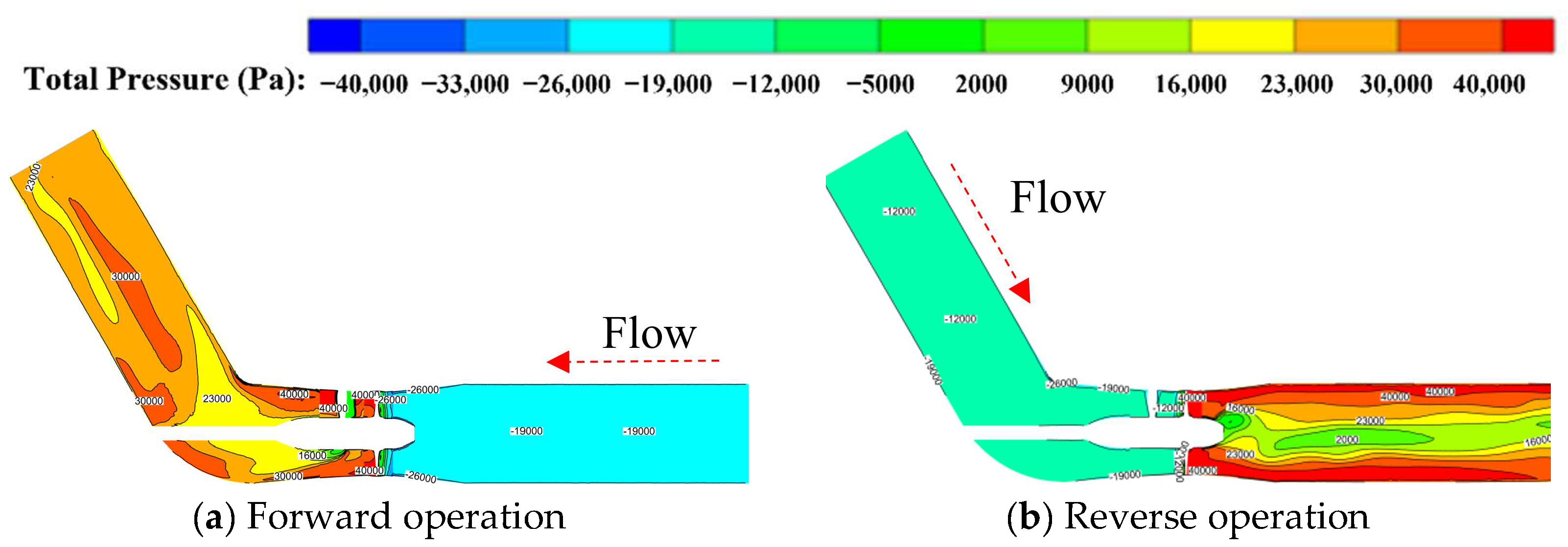
The total pressure distribution clouds of the middle section of the fluid calculation domain for both forward and reverse directions of the bidirectional axial flow pump taking 0.9Qd, 1.0Qd, 1.1Qd are shown in Figure 13, Figure 14 and Figure 15.
According to Figure 13, Figure 14 and Figure 15, the total pressure distribution in the inlet pipe is relatively uniform under forward and reverse operation. During forward operation, the total pressure distribution in the outlet elbow becomes more and more uniform with the increase of flow. During reverse operation, due to the rotation of the impeller, there is no circulation recovery structure such as guide vane at the impeller outlet, resulting in uneven total pressure distribution in the center of the outlet, obvious stratification, low total pressure in the middle area, and high total pressure at the side wall of the outlet pipe. With the increase of flow rate, the distribution uniformity of total pressure of outlet water is improved. Forward operation and reverse operation affect the size of the hydraulic loss of the inlet pipe and the recovery of more and less water pressure energy from the outlet pipe. Considering the head under the same flow condition, through the static pressure distribution cloud diagram, it can be concluded that the forward running inlet pipe static pressure distribution is more uniform than the reverse running, so the forward running inlet pipe hydraulic loss is less than the reverse running. The hydrostatic pressure distortion area in the forward running outlet bend is less than the reverse running, and the outlet pressure recovery is more than the reverse running, as reflected in the energy performance curve (shown in Figure 7c,d). At the same flow rate, the head of forward operation is higher than that of reverse operation.
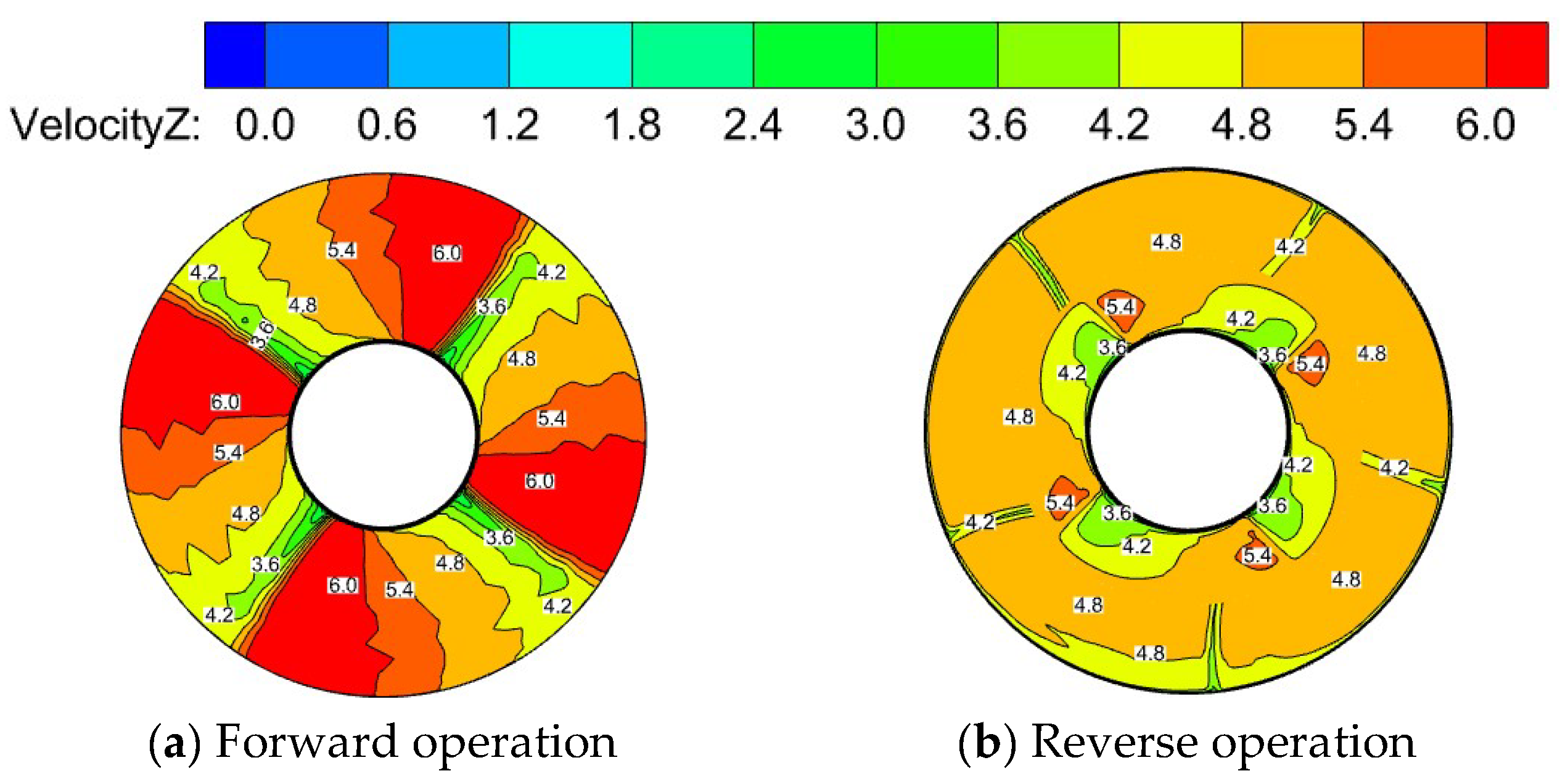
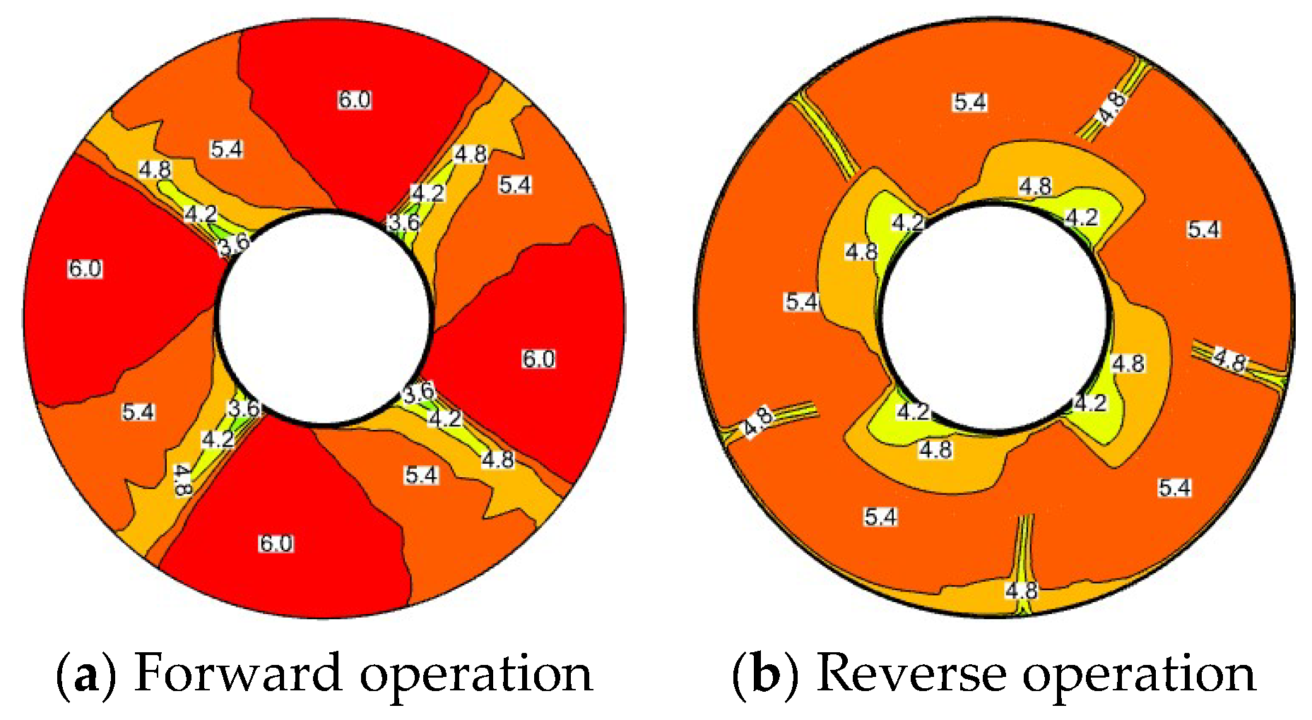
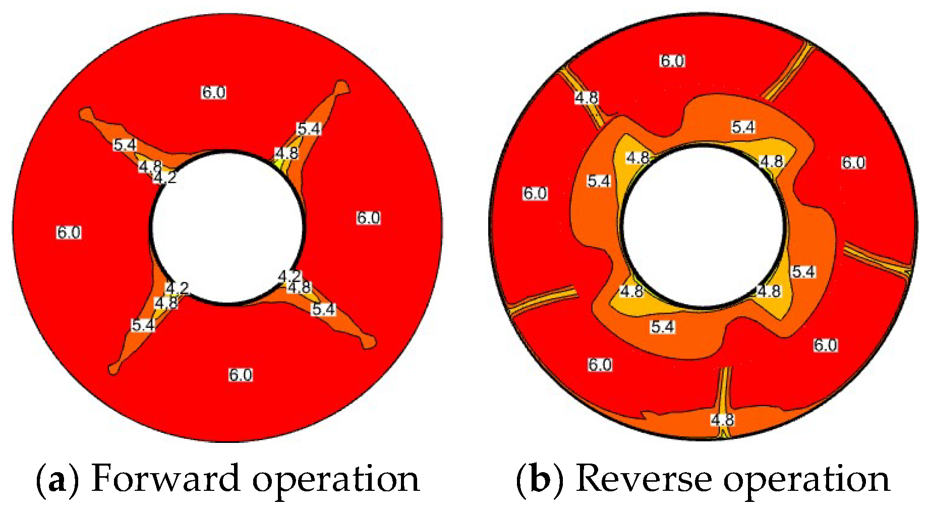
The axial flow velocity distribution clouds of the impeller inlet for both forward and reverse directions of the bidirectional axial flow pump are taken as 0.9Qd, 1.0Qd, and 1.1Qd as shown in Figure 16, Figure 17 and Figure 18.
As can be obtained from Figure 16, Figure 17 and Figure 18, the uniformity of the axial flow velocity of the impeller inlet increases with the increase of the flow rate under both forward and reverse operation. In forward operation, because the number of impeller blades is 4, the impeller inlet axial velocity is obviously divided into 4 areas, and in reverse operation, the impeller inlet is not only influenced by the number of impeller blades, but also by the number of guide vanes, and the impeller inlet axial velocity is divided into 4 areas near the hub and 5 areas near the rim. Overall, the uniformity of axial velocity at the inlet of forward running impeller is higher than that of the reverse running impeller. This conclusion can also be explained by Figure 9.
The vortex distribution inside the impeller for the forward and reverse directions of the bidirectional axial flow pump taking 0.9Qd, 1.0Qd, and 1.1Qd is shown in Figure 19, Figure 20 and Figure 21. In this paper, the vortex discrimination criterion is Q-Criterion, which was proposed by Hunt et al. in 1988 [20,21].
As shown in Figure 19, Figure 20 and Figure 21, forward operation compared to reverse, impeller blade forward, and reverse pressure difference is larger. So, in the blade of the suction surface slightly longer leakage vortex is indicates, whereas in the corresponding reverse operating conditions, the blade of slightly pointed leakage vortex is relatively slightly small. The area of tip clearance vortex in reverse operation is slightly larger than that in forward operation. Due to the front guide vane and elbow in reverse operation, the vortex area at the inlet side of the blade is also significantly larger than that in forward operation. At the same time, the reverse operation also causes an annular vortex belt near the rim between the guide vane and the impeller. In both forward and reverse operation, the vortex area decreases with the increase of flow. This also reflects the higher energy performance of the forward operating impeller compared to the reverse (shown in Figure 7a,b).

5. Conclusions

This paper reveals the forward and reverse energy and internal flow characteristics of the bidirectional axial flow pump through numerical calculations and experimental tests on the bidirectional axial flow pump, and the following conclusions are obtained:
(1)
The comparative analysis of the numerical calculation results and tests of the energy characteristics of the bidirectional axial flow pump shows that the predictions of the forward and reverse numerical calculations are relatively accurate, and the error is basically within 5%. Compared with the forward prediction, the accuracy of the reverse numerical calculation is slightly worse, and the numerical calculation results are credible.
(2)
The test results show that the bidirectional axial flow pump design working condition flow rate Q = 368 L/s, head H = 3.767 m, and efficiency η = 80.37% in forward operation and bidirectional axial flow pump design working condition flow rate Q = 316 L/s, head H = 3.658 m, efficiency η = 70.37% in reverse operation. The forward operation is about 15% larger than the reverse operation design working condition flow rate, the design head is about 3.70 m, and the design working efficiency is about 10% higher in the forward direction than in the reverse direction.
(3)
The numerical calculation results show that under the forward design condition (Q = 368 L/s), the proportion of hydraulic loss is 6.22%, and under the reverse design condition (Q = 316 L/s), the proportion of hydraulic loss is 11.81%, with a difference of about 6%. The uniformity of impeller inlet flow velocity is about 12% higher than that under the reverse operation. The main reason for the difference in hydraulic loss and flow velocity uniformity between forward and reverse operation is that during reverse operation, curved guide vanes are placed in front, which reduces the flow velocity uniformity at the inlet of the impeller, resulting in an increase in the bad flow pattern of the inlet water of the impeller, and because the outlet water has no circulation recovery structure such as guide vanes, the ability of converting kinetic energy into pressure energy of the outlet water is weakened, and the proportion of hydraulic loss is increased.
(4)
In the forward operation, the inlet water is straight pipe, and in the reverse operation, the inlet water is elbow. Under the forward and reverse operation, the inlet water flow pattern is relatively good. In the forward and reverse operation, with the increase of flow, the outlet water streamline, the total pressure distribution of outlet water, the uniformity of impeller inlet flow velocity, and the vortex in the impeller domain are improved. The internal flow fields, such as outlet streamline, total outlet pressure distribution, impeller inlet velocity uniformity, and impeller domain vortex, under forward operation are better than those under reverse operation, so the performance of forward operation is better than that of reverse operation.

Author Contributions

Concept design, C.X. and A.F.; numerical calculation, T.F. and C.Z.; experiment and data analysis, T.Z. and F.Y.; manuscript writing, C.X. and A.F. All authors have read and agreed to the published version of the manuscript.

Funding

This research was funded by Anhui Province Natural Science Funds for Youth Fund Project, grant number 2108085QE220. Key scientific research project of Universities in Anhui Province, grant number KJ2020A0103. Anhui Province Postdoctoral Researchers’ Funding for Scientific Research Activities, grant number 2021B552. Anhui Agricultural University President’s Fund, grant number 2019zd10. Stabilization and Introduction of Talents in Anhui Agricultural University Research Grant Program, grant number rc412008.

Data Availability Statement

Not applicable.

Conflicts of Interest

The authors declare no conflict of interest.

References

  1. Tang, F.; Liu, C.; Wang, G.; Xie, W.; Zhou, J.; Cheng, L. Study on hydraulic model of bidirectional axial flow pump with plane S-shaped channel. J. Agric. Mach. 2003, 34, 50–53. [Google Scholar]
  2. Ma, P.; Wang, J.; Li, H. Numerical Analysis of Pressure Pulsation for a Bidirectional Pump under Positive and Reverse Operation. Adv. Mech. Eng. 2014, 6, 730280. [Google Scholar] [CrossRef]
  3. Ma, P.; Wang, J. An analysis on the flow characteristics of bi-directional axial-flow pump under reverse operation. Proc. Inst. Mech. Eng. Part A J. Power Energy 2017, 231, 239–249. [Google Scholar] [CrossRef]
  4. Xie, C. Study on Energy and Cavitation Characteristics of S-Shaped Airfoil Bidirectional Axial Flow Pump. Ph.D. Thesis, Yangzhou University, Yangzhou, China, 2018. [Google Scholar]
  5. Ma, P.; Wang, J. Influence of geometric parameters of straight guide vane on flow field and hydraulic performance of bidirectional pump. J. Hydraul. Eng. 2017, 48, 1126–1133. [Google Scholar]
  6. Meng, F.; Pei, J.; Li, Y.; Yuan, S.; Chen, J. Influence of guide vane position on hydraulic performance of bidirectional Shaft Tubular pump device. J. Agric. Mach. 2017, 48, 135–140. [Google Scholar]
  7. Meng, F.; Li, Y.; Yuan, S.; Yuan, J.; Zheng, Y.; Yang, P. Effect of blade root clearance on hydraulic performance of bidirectional axial flow pump. J. Agric. Mach. 2020, 51, 131–138. [Google Scholar]
  8. Zheng, Y.; Li, C.; Gu, X.; Chen, Y. Effect of S-shaped elbow on performance and stability of bidirectional axial extension pump. J. Eng. Thermophys. 2019, 40, 319–327. [Google Scholar]
  9. Jin, K.; Chen, Y.; Tang, F.; Shi, L.; Liu, H.; Zhang, W. Influence of shaft position on hydraulic characteristics of two-way tubular pump device. J. Hydroelectr. Eng. 2021, 40, 67–77. [Google Scholar]
  10. Kan, K.; Zhang, Q.; Xu, Z.; Chen, H.; Zheng, Y.; Zhou, D.; Maxima, B. Study on a horizontal axial flow pump during runaway process with bidirectional operating conditions. Sci. Rep. 2021, 11, 21834. [Google Scholar] [CrossRef] [PubMed]
  11. Yang, F.; Zhang, Y.; Yuan, Y.; Liu, C.; Li, Z. Numerical and Experimental Analysis of Flow and Pulsation in Hump Section of Siphon Outlet Conduit of Axial Flow Pump Device. Appl. Sci. 2021, 11, 4941. [Google Scholar] [CrossRef]
  12. Fang, X.; Hou, Y.; Cai, Y.; Chen, L.; Lai, T.; Chen, S. Study on a high-speed oil-free pump with fluid hydrodynamic lubrication. Adv. Mech. Eng. 2020, 12, 1687814020945463. [Google Scholar] [CrossRef]
  13. Stuparu, A.; Baya, A.; Bosioc, A.; Anton, L.; Mos, D. Experimental investigation of a pumping station from CET power plant Timisoara. In IOP Conference Series: Earth and Environmental Science; IOP Publishing: Bristol, UK, 2019; Volume 240. [Google Scholar]
  14. Xie, C.; Tang, F.; Yang, F.; Zhang, W.; Zhou, J.; Liu, H. Numerical simulation optimization of axial flow pump device for elbow inlet channel. In IOP Conference Series: Earth and Environmental Science; IOP Publishing: Bristol, UK, 2019; Volume 240. [Google Scholar]
  15. Shi, L.; Zhang, W.; Jiao, H.; Tang, F.; Wang, L.; Sun, D.; Shi, W. Numerical simulation and experimental study on the comparison of the hydraulic characteristics of an axial-flow pump and a full tubular pump. Renew. Energy 2020, 153, 1455–1464. [Google Scholar] [CrossRef]
  16. Shi, L.; Tang, F.; Zhou, H.; Tu, L.; Xie, R. Axial-flow pump hydraulic analysis and experiment under different swept-angles of guide vane. Trans. Chin. Soc. Agric. Eng. 2015, 31, 90–95. [Google Scholar]
  17. Zhang, W.; Tang, F.; Shi, L.; Hu, Q.; Zhou, Y. Effects of an Inlet Vortex on the Performance of an Axial-Flow Pump. Energies 2020, 13, 2854. [Google Scholar] [CrossRef]
  18. Yang, F.; Zhao, H.; Liu, C. Improvement of the Efficiency of the Axial-Flow Pump at Part Loads due to Installing Outlet Guide Vanes Mechanism. Math. Probl. Eng. 2016, 2016, 6375314. [Google Scholar] [CrossRef]
  19. Sun, Z.; Yu, J.; Tang, F. The Influence of Bulb Position on Hydraulic Performance of Submersible Tubular Pump Device. J. Mar. Sci. Eng. 2021, 9, 831. [Google Scholar] [CrossRef]
  20. Wang, Y.; Zhang, W.; Cao, X.; Yang, H. The applicability of vortex identification methods for complex vortex structures in axial turbine rotor passages. J. Hydrodyn. 2019, 31, 700–707. [Google Scholar] [CrossRef]
  21. Tang, X.; Jiang, W.; Li, Q.; Gaoyang, H.; Zhang, N.; Wang, Y.; Chen, D. Analysis of hydraulic loss of the centrifugal pump as turbine based on internal flow feature and entropy generation theory. Sustain. Energy Technol. Assess. 2022, 52, 102070. [Google Scholar]
Figure 1. “S” shaped airfoil.
Water 14 02839 g001
Figure 2. Impeller of bidirectional axial flow pump.
Water 14 02839 g002
Figure 3. Schematic diagram of forward and reverse operation of “S” shaped airfoil bidirectional axial flow pump. (Black indicates forward operation, Red indicates reverse operation).
Water 14 02839 g003
Figure 4. Grid diagram of each component.
Water 14 02839 g004
Figure 5. Plan of high precision hydraulic machinery test bench. 1. Water inlet tank; 2. Tested pump; 3. Pressure outlet tank; 4. Bifurcated water tank; 5~6. Flow in situ calibration device; 7. Working condition regulating gate valve; 8. Pressure stabilizing rectifier cylinder; 9. Electromagnetic flowmeter; 10. Operation control gate valve; 11. Auxiliary pump unit.
Water 14 02839 g005
Figure 6. Comparison curve of numerical calculation and test energy characteristics.
Water 14 02839 g006
Figure 7. Numerical calculation curve of energy characteristics: (a) Forward bidirectional pump impeller; (b) Reverse bidirectional pump impeller; (c) Forward bidirectional pump; (d) Reverse bidirectional pump.
Water 14 02839 g007
Figure 8. Proportion of hydraulic loss.
Water 14 02839 g008
Figure 9. Uniformity of flow velocity at impeller inlet.
Water 14 02839 g009
Figure 10. 0.9Qd 3D streamline diagram.
Water 14 02839 g010
Figure 11. 1.0Qd 3D streamline diagram.
Water 14 02839 g011
Figure 12. 1.1Qd 3D streamline diagram.
Water 14 02839 g012
Figure 13. 0.9Qd clouds of total pressure distribution in the middle cross section.
Water 14 02839 g013
Figure 14. 1.0Qd clouds of total pressure distribution in the middle cross section.
Water 14 02839 g014
Figure 15. 1.1Qd clouds of total pressure distribution in the middle cross section.
Water 14 02839 g015
Figure 16. 0.9Qd impeller inlet axial flow velocity distribution cloud diagram.
Water 14 02839 g016
Figure 17. 1.0Qd impeller inlet axial flow velocity distribution cloud diagram.
Water 14 02839 g017
Figure 18. 1.1Qd impeller inlet axial flow velocity distribution cloud diagram.
Water 14 02839 g018
Figure 19. 0.9Qd impeller internal vorticity distribution diagram.
Water 14 02839 g019aWater 14 02839 g019b
Figure 20. 1.0Qd impeller internal vorticity distribution diagram.
Water 14 02839 g020
Figure 21. 1.1Qd impeller internal vorticity distribution diagram.
Water 14 02839 g021
Table 1. Parameters of design working conditions of “S” shaped airfoil bidirectional axial flow pump.
ParametersForwardReverse
Blade angle
Impeller diameter(300–0.2) mm(300–0.2) mm
Rotating speeds1450 rpm1450 rpm
Design flow368 L/s316 L/s
Design head3.70 m3.70 m
Design point ratio speed11871124
Table 2. Grid irrelevance analysis table (Forward running, Q = 400 L/s).
Serial NumberNη (%)Serial NumberNη (%)
11,607,28876.415043,402,09377.0300
22,143,05076.474554,018,22077.0360
32,678,81377.04056//
Publisher’s Note: MDPI stays neutral with regard to jurisdictional claims in published maps and institutional affiliations.