Abstract
The successful fish upstream movement through a dam/gate is closely associated with the hydraulic conditions of a fishway. To improve the passage efficiency, this study investigated the upstream swimming behaviors of juvenile grass carp, a representative fish of four major Chinese carps, under characteristic hydraulic conditions of a designed vertical slot fishway model. The impacts of different discharges and baffle lead angles on the successful movement of test fish were analyzed, and the selection of the movement trajectory was studied through overlay of their upstream swimming trajectories on the water flow field resulting from numerical modeling. We found that under the same discharge, the percentage of successful test fish movement with a lead angle of 45° was higher than 60° and 30°. Within a fixed lead angle, the higher the discharge, the lower the percentage of successful movement. During upstream movement, the test fish had a preferred water velocity of 0.01–0.45 m/s in the pool, and avoided areas where the turbulence kinetic energy (TKE) was greater than 0.012 m2/s2. These results provide a basis for the hydraulic design of vertical slot fishways and a reference for studying swimming behaviors of other fish species.
1. Introduction
The four major Chinese carp, including (Mylopharyngodon piceus (Cyprinidae, Richardson)), grass carp (Ctenopharyngodon idellus (Cyprinidae, Cuvier et Valenciennes)), silver carp (Hypophthalmichthys molitrix (Cyprinidae, Valenciennes)), and bighead carp (Aristichthys nobilis (Cyprinidae, Richardson)), are important economic fish species in China and belong to potamodromous fish [1]. The construction of flood control dams has blocked the migration routes between distinct habitats in the three main life stages (spawning, feeding, and overwintering) [2,3], resulting in a continuous decline in their populations due to a lack of resources [4,5].
Fishway engineering is important for ecological protection or remedial projects to allow fish (or other aquatic species) pass through [6]. Their hydraulic design should be consistent with the swimming behavior of the fish species in case [7], otherwise it will be affecting the fish passage efficiency and even leading to migration failure [8]. Noonan et al. [9] reported that the mean fish passage efficiency was only 41.7% for non-salmonids from 65 papers published during 1960–2011. Many other studies reported much lower efficiencies, including several non-effective facilities [10,11]. These indicate that current fishways are far from achieving the primary conservation goal of restoring the connectivity of freshwater ecosystem.
Recent studies have shown that hydraulic variables, such as water velocity and turbulence kinetic energy (TKE), have a positive or negative impact on the fish swimming behaviors [12,13,14,15]. The TKE represents the fluctuation of water velocity and is used to characterize the intensity of turbulence [16]. Many periods in the swimming behavior of the fish are influenced by energy costs [13,17], capture efficiency [18], habitat selection [19] and fish density [20], which are influenced by the TKE. Research on the relationship between fish behaviors and the hydrodynamic factors in a characteristic water flow field is in its upcoming. The current information is limited for understanding the swimming behavior of fish in fishways and thus, to guide the hydraulic design of fishways.
The design of fishways in China mostly refers to that of developed countries [21,22]. However, the study species in the developed countries are most often salmons or other fish with strong swimming ability [22,23]. In China, cyprinids like the four major Chinese carp are the most valuable freshwater fishes, but they have small body length and weak swimming ability, so the research results are difficult to be directly applied in China [24,25,26]. Hu [27] and He et al. [28] found that the feeding migration period of juveniles of the four major Chinese carps in the Yangtze River is concentrated from mid-July to the end of August, when the body lengths of juvenile fish are mainly between 5–15 cm. Therefore, studies on the swimming behaviors of juvenile fish with body lengths within that range are of practical significance for the protection of fish resources in the Yangtze River.
The vertical slot fishway is one of most important structural types of fishway engineering [29]. The vertical slot section covers the entire water depth and is suitable for the migration of fish at the surface, middle layer, and bottom [30]. Therefore, it has a wide application range. In this study, a physical multi-level pool model of a vertical slot fishway was established using an indoor water tank. Different flow regimes were created by changing the discharge and the baffle lead angle. Continuous upstream movement tests of juvenile grass carp under multi-pool conditions were conducted. Through overlay analysis of the water flow field of the numerical modeling and the swimming trajectories of the test fish, we studied the selection of the movement trajectory by the test fish under different characteristic flow conditions. The impacts of water velocity and TKE on the upstream swimming behaviors of the fish were preliminarily revealed, providing a reference for the hydraulic design of fishways for the upstream movement of the four carp species. Many other studies investigated the fish passage efficiency using either the numerical model [30,31,32] or the physical model [14]. The contribution of this study lies in that we used both the numerical and physical modeling to get information about the use of hydraulic flow by juvenile grass carp in a vertical slot fishway.
2. Materials and Methods
2.1. Physical Model
2.1.1. Test Equipment
The fishway model was built in an indoor rectangular glass tank with a length of 15 m, a width of 1.2 m, and a depth of 1.8 m. Three sections were included in the model: the inflow section, the pool section, and the outflow section, wherein six levels of pools of the same size comprised the pool section. Each pool had a length of 1.5 m, a width of 1.2 m, a vertical slot width of 0.15 m, and a fishway bottom slope of 2.5%. The six pool levels were numbered sequentially from upstream to downstream starting from Pool Level-1. The baffle and bottom of the fishway model were made of gray plastic plates. An illustration of the vertical slot fishway model is in Figure 1a,b.
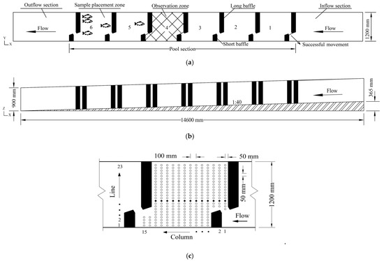
Figure 1.
Illustration of vertical slot fishway model. (a) Top view. (b) Front view. (c) Water velocity measurement points (which are in a plane parallel to 60 and 60 mm from the bottom) in observation zone (Pool 4, the black dots indicate Line 10).
Pool Level-6 at the downstream end of the model was the zone in which test fish were placed. Before the start of the test, the fish were temporarily placed in this pool where an active net fish screen was set at the entrance and exit of this pool. Pool Level-1 to Level-5 were the main movement areas of the test fish and were used to observe the swimming behaviors and movement trajectories. Pool Level-4 was located in the middle of the test section, and the water flow in this region was less affected by the upstream and downstream hydraulic boundaries. This was the observation zone for the upstream movement of the test fish. Two cameras were mounted on the upper part of the model, and the viewing angle could cover the entire movement area. The inlet of Pool Level-1 at the upstream was the end of the fish movement test. The successful movement indicates that the test fish in Pool Level-6 can successfully swim out from the Pool Level-1 in 20 min, and the fish could ascend with return during the time period but has to swim out before the timeout.
An Acoustic-Doppler Velocimeter (ADV) was used in this study to measure (with frequency of 100 Hz and time of 40 s for each measurement point) the three-dimensional field of water velocity in the observation zone (Pool Level-4) of the model. It was observed that the test fish usually swam 6-7cm above the bottom. Thus, the horizontal plane at 0.06 m from the bottom plate was selected as the single plane for measuring the water velocity. Measurement points of fifteen columns (along the direction of the water flow) by twenty-three lines (perpendicular to the columns) for water velocity were arranged. The measuring points on each column were separated by 0.05 m, and the column-to-column spacing was 0.10 m (Figure 1c). Thus, the water velocity plane was measured with a total of 287 points.
Additionally, the ADV post-process software was used to pre-process the measured data, and the ZooTracer software (https://www.microsoft.com/en-us/research/project/zootracer/, accessed on 30 April 2021) was used for trajectory tracking of the test fish. The trajectory length of the upstream movement of the test fish and the upstream swimming speed could be obtained based on the swimming time and the upstream swimming trajectory extracted by the ZooTracer software. Note that the ZooTracer software could process the video into frames of images, identify the trajectory (namely a series of positions) of a movement object, and output a file with coordinate information.
2.1.2. Test Fish
The test fish were collected in August 2017, using the fishing net from a fishery in Beijing and were transported to the test site by a professional aquatic transport container. A total of 140 grass carp individuals (body length: 7.01–14.70 cm) were used. According to the training and holding requirements of the physiological test, the test fish were placed in a glass pool (2.0 × 1.5 m) with a water depth of 1.0 m for 2 weeks. The holding water was tap water with 5 days of aeration, in the holding and test, the water temperature was 23 ± 1 °C, the pH value was 7.5, and the concentration of dissolved oxygen was greater than 8 mg/l. Feeding was stopped two days before the test. Because the water used in the experiment was from the underground reservoir, the water condition was almost stable.
2.1.3. Test Method and Condition
Different flow conditions in the fishway pool were created by changing the lead angle (30° (Figure 2a), 45° (Figure 2b), and 60° (Figure 2c)) of baffles of the fishway. Under each lead angle, the upstream movement test was carried out under a small discharge (0.011 m3/s), a medium discharge (0.025 m3/s), and a large discharge (0.041 m3/s). The impacts of two typical hydraulic variables including water velocity (m/s) and TKE (m2/s2) on the upstream swimming behaviors of the fish were analyzed based on the percentage of successful movement and the movement trajectory. The TKE is calculated as:
where is instantaneous velocities, is fluctuating velocities, is the temporal mean of fluctuating velocities. , , and are the fluctuating velocity in the directions of x, y, and z, respectively.

Figure 2.
Illustration of the fishway model of various baffle lead angles and corresponding recirculation zones (the RZ denotes the recirculation zone; the blue line denotes the vertical slot. (a–c) are fishways with lead angles of 30°, 45°, and 60°, respectively).
Under each test condition, five test fish were randomly selected and placed in the sample placement zone for 5–7 min. When no obvious change in swimming direction was observed, the exit block of the sample placement zone was lifted, and the test began. The swimming behaviors of the test fish were observed by cameras, and the time for successful movement and the number of passes were recorded. According to experience, the time from adaptation to successful movement was 10–30 min for the test fish. Therefore, 20 min was selected as the test time for one test condition. When the test fish still had not reached the exit of Pool Level-1 (Figure 1a) when the time was exceeded, it was determined as a failure of movement.
In each trial, 5 fish were tested together not individually for consideration of the population behaviors. In order to eliminate accidental error in the test as much as possible, three to four sets of experiments were conducted for each test condition, and the other five fish were replenished for each set (no test fish was reused).
2.2. Numerical Model
2.2.1. Simulation
To improve the test efficiency and obtain detailed characteristic hydraulic parameters, the Fluent software was used to simulate the three-dimensional flow field of the fishway pool. Using the software, the Navier–Stokes equation can be solved within acceptable computational cost by coupling the Reynolds Averaged Navier–Stokes (RANS) [33] and the Re-Normalization Group (RNG) k-ε turbulence model based on the volume of fluid (VOF) two-phase flow [34]. A hexahedral mesh with a grid length of 1.22 cm and a total grid number of 1,033,101 was used for the numerical model. The boundary conditions at the upstream inlet had a pressure-inlet (water depths are 15, 24, and 35 cm for small, medium, and large discharges, respectively; water velocity is 0 for the three cases), and the downstream outlet had a pressure-outlet (water depths are 30, 24, and 22 cm for small, medium, and large discharges, respectively). To ensure the stability of the calculation, under-relaxation was applied to the transport equations of momentum and scalar, and the Pressure-Implicit with Splitting of Operators (PISO) algorithm was used for the pressure-velocity coupling. The time step was taken as 0.005 s and the iteration accuracy was set to 10−4.
2.2.2. Validation
To evaluate the predictive performance, the Mean Absolute Percentage Error (MAPE) is introduced and calculated as:
where and are observed and simulated values, respectively, and n is the total number of values. According to other similar studies [35,36], the predictive performance can be accepted when the MAPE value of water velocity is less than 10%.
2.3. Fish Trajectory Analyses
To analyze the impacts of hydraulic variables in the fishway on the upstream swimming behaviors of the test fish, by overlay charts of the upstream swimming trajectories with the water velocity field and TKE field, the relationship between the upstream swimming trajectories and the hydraulic characteristics of the pool can be obtained.
The trajectories of 16 representative test fish (9 for small, 5 for medium, and 2 for large discharges) in the fishway with a lead angle of 45° were selected for analysis, because these fish had clearer movement trajectories. Some fish that could not successfully pass through the fishway and some fish with disordered movement trajectories were not presented. A total of 100 points along each trajectory were evenly selected to extract the water velocity and TKE.
3. Results
3.1. Physical Versus Numerical Model Results
The numerical simulation results of the water flow field were compared with the physical measurement results for the case where the lead angle was 60° under a small discharge. The measured and simulated flow velocities (Figure 3a) as well as TKE (Figure 3b) of the measuring points at Line 10 in the observation zone were compared. There were a total of 15 measurement point columns along the direction of the water flow (Figure 1c). The range of MAPE values of water velocity for measured points from Column 1 to 15 were 3.5–10%. The MAPE value of water velocity for all measured points from all columns was 7.8%. Except for the MAPE value of water velocity for Column 1 (12.5%), the MAPE values of water velocity for other columns were all smaller than 10%. The range of MAPE values of TKE were 44.3~86.1%, greater than 50% for measured points of most columns. The TKE values of measured points were greater than simulated ones, and the closer to the baffle the bigger the difference between them. Overall, the numerical simulation results were largely consistent with the physical measurement results, indicating that the numerical simulation accuracy was good and could meet the requirement to study the water flow field in fishway pool.
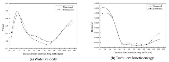
Figure 3.
Comparison between measured and simulated water velocities and turbulent kinetic energies of measurement points at Line 10 in observation zone (lead angle = 60°, Q = 0.011 m3/s. (a) Water velocity, (b) Turbulent kinetic energy).
3.2. Percentage of Successful Movement
At the same lead angle, the percentage of successful movement of the test fish gradually decreased with the increase of discharge: the percentage of successful movement of the test fish at a lead angle of 30° was reduced from 67% to 10%; at lead angle of 45° from 87% to 33%; and at lead angle of 60° from 80% to 30%.
The range of maximum water velocity at the vertical slot was 0.544–0.678 m/s under a low discharge, and the range of maximum water velocity at the vertical slot increased to 0.851–1.050 m/s under a large discharge (Table 1). The percentages of successful movement of the test fish at the three lead angles under the same discharge were compared. The percentage at 45° was larger than that at 60°, which was larger than that at 30°. For example, under a medium discharge, the percentages of successful movement of the test fish at lead angles of 45°, 60°, and 30° were 73%, 53%, and 35%, respectively, indicating that the fishway with a lead angle of 45° was more suitable for the upstream movement of the test fish.

Table 1.
Results of successful upstream movement.
3.3. Upstream Movement Trajectories
The upstream movement trajectories of the test fish and the water velocity field (Figure 4a–c) and the TKE field (Figure 5a–c) in the observation zone were overlaid, respectively. The water flowed from right to left, and the fish swam from left to right. The graphs shown on the left, middle, and right columns correspond to test conditions under small, medium, and large discharges under each baffle lead angle. Note that the trajectories of only those test fish moved successfully were selected for analysis.
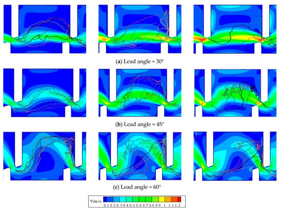
Figure 4.
Overlay chart of upstream movement trajectories of test fish with water velocity field in observation zone. (Discharges of the left, middle, and right columns are 0.011, 0.025, 0.041 m3/s, respectively. (a–c) are fishways with lead angles of 30°, 45°, and 60°, respectively).
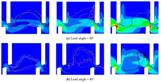

Figure 5.
Overlay chart of upstream movement trajectories of test fish with turbulent kinetic energy field in observation zone. (Discharges of the left, middle, and right columns are 0.011, 0.025, 0.041 m3/s, respectively. (a–c) are fishways with lead angles of 30°, 45°, and 60°, respectively).
Under a small discharge, the test fish generally migrated along the mainstream or mainstream edge regardless of the lead angle in the fishway (Trajectory range 1 or 2 in Figure 6). As the discharge increased, most of the test fish avoided areas with high water velocity and TKE and chose to migrate through the recirculation zone (Figure 2) on either side of the mainstream. Specifically, under a large discharge, most of the test fish directly crossed the recirculation zone from the downstream inlet to the rear of the upstream short baffle, passed through the mainstream, reached the rear of the upstream long baffle, and then went through the vertical slot to complete a successful upstream movement (Trajectory range 2 in Figure 6). The upstream swimming trajectories of these test fish can be summarized into two trajectory ranges (Figure 6).
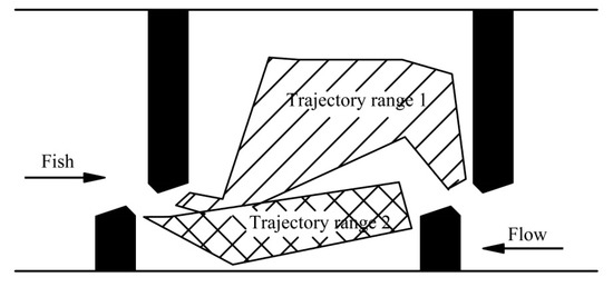
Figure 6.
Trajectory ranges of test fish through observation zone.
3.4. Hydraulic Variables in Fishway Pool
The movement efficiency in the fishway with a lead angle of 45° was higher than in those with other lead angles. The observation zone of the fishway with a lead angle of 45° (Figure 4 and Figure 5) was taken as an example to analyze the impacts of hydraulic variables in the pool on the upstream swimming behaviors of the test fish.
Under the low discharge, among the 13 test fish of successful movement, eight migrated along Trajectory range 1 and five migrated along Trajectory range 2. The water velocity of Trajectory range 1 ranged from 0.10 to 0.40 m/s, and the range of TKE was from 0.002 to 0.006 m2/s2. The water velocity of Trajectory range 2 ranged from 0.05 to 0.10 m/s, and the range of TKE was from 0.004 to 0.012 m2/s2 (Table 2).

Table 2.
Relationship between trajectory selection of test fish and water velocity and turbulent kinetic energy in observation zone. (lead angle = 45°).
Under the medium discharge, the 11 fish of successful movement all migrated along Trajectory range 1. The water velocity of Trajectory range 1 was 0.05–0.61 m/s, and the range of TKE was 0.002–0.008 m2/s2.
Under the large discharge, it was difficult for the test fish to complete a successful upstream movement. Most of the fish hesitated in the recirculation zone of the pool and tried to swim upstream repeatedly. Only 5 of the 15 fish migrated successfully, which all migrated along Trajectory range 1. The water velocity of Trajectory range 1 was 0.10–0.64 m/s, and the range of TKE was 0.01–0.03 m2/s2 (Table 2).
The water velocity and TKE distributions on upstream movement trajectories of the 16 representative test fish are shown in Figure 7. The average water velocity ranged from 0.13 to 0.44 m/s, and the range of average TKE was 0.0038–0.0185 m2/s2. For the total of 1600 points (16 test fish by 100 points for each trajectory), 81% of points of water velocity was distributed between 0.01 and 0.45 m/s, and 84% of points of TKE was between 0.0005 and 0.012 m2/s2.
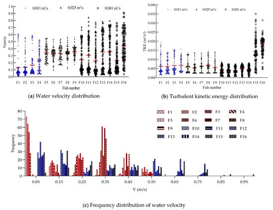
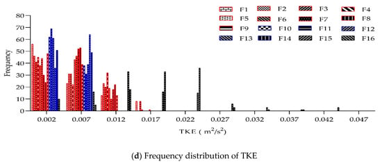
Figure 7.
Water velocity and turbulent kinetic energy distributions on upstream movement trajectories of 16 representative test fish. (In (a,b), F1, F2, …, F16 indicate the 16 representative test fish; the blue dots indicate fish upstream movement trajectories along Trajectory range 2, while the black dots indicate those along Trajectory range 1; the red lines are the mean values of water velocity and turbulent kinetic energy; in (c,d), red, blue and black, indicate low, medium, and large discharges).
In summary, the range of water velocity in the pool that the test fish could adapt to during upstream movement was 0.05–0.64 m/s (the favorite range was 0.01–0.45 m/s), and the TKE of the water flow on the trajectory should not be higher than 0.012 m2/s2 to ensure a high percentage of successful upstream movement.
3.5. Hydraulic Variables in Vertical Slot
It can be seen from the upstream swimming trajectories of the test fish that under various lead angles and different discharges, the fish all chose to migrate along the trajectory close to the long baffle when passing through the vertical slot (Figure 4 and Figure 5). Taking the observation zone in the fishway with a lead angle of 45° as an example, we analyzed the impacts of the hydraulic characteristics at the vertical slot (Figure 8a–f).
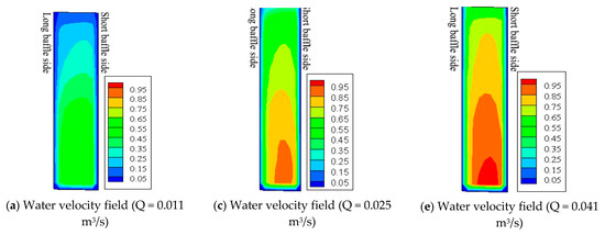
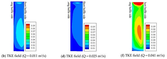
Figure 8.
Distribution diagram of fields of water velocity (m/s) and turbulent kinetic energy (m2/s2) at vertical slot. (lead angle = 45°, the left side of each subfigure shows the long baffle side, and the right side shows the short baffle side. (a,c,e) are water velocity field under the discharge of 0.011, 0.025, 0.041 m3/s, respectively. (b,d,f) are TKE field under the discharge of 0.011, 0.025, 0.041 m3/s, respectively).
Our analysis showed that the water velocity at the vertical slot was evenly distributed from left to right, and the difference between the left and right sides was small. However, the TKE had a clear increasing trend from left to right (Figure 8a–f).
4. Discussion
We studied the percentage of successful movement, the upstream movement trajectories, as well as the influences of hydraulic variables (water velocity and TKE) on juvenile grass carp under different water flow conditions resulting from different discharges and baffle lead angles.
4.1. Physical Versus Numerical Model Results
The TKE values of measured points were greater than simulated ones, and the closer to the baffle the bigger the difference between them. The results were consistent with Sanagiotto et al. [33], Baki et al. [34] and Tran et al. [36], for all their simulations in fishways reported MAPE values greater than 50% for turbulence kinetic energy. The accuracy of numerical simulation depends on the boundary conditions. The water velocity and TKE of mainstream are the most critical factors to depict the water flow field of vertical slot fishway, which has been proved by other earlier studies [33,37,38]. In this experiment, a lot of scenario combinations were taken with different baffle lead angles and discharges. The accuracy of numerical simulations can be proved by one of these scenario combinations.
4.2. Influence of Hydraulic Structure on Percentage of Successful Movement
The hydraulic structure of the fishway has an influence on the percentage of successful movement for the fish. In this study, analysis of the hydraulic characteristics of the fishway pools with different lead angles showed that the bending degree of the mainstream in the fishway with a lead angle of 60° was the largest, the flow distance was long with much blending, and the energy attenuation in the pool was the largest; the water velocity at the vertical slot under the same discharge was the smallest, but in this case, the mainstream seriously deviated from the center of the pool and a large recirculation zone formed at one side of the mainstream. The flow regime of the fishway with a lead angle of 45° was between those in the fishways with lead angles of 30° and 60°. In this case, the mainstream was centered, the water velocity at the vertical slot was moderate, and the size of the recirculation zones on both sides of the mainstream were basically the same, leading to the highest percentage of successful movement.
Several other studies were also taken to investigate the water flow field of hydraulic structure and optimize the layout and size for fishways using numerical or physical models [9,30,31,39,40,41]. For example, Quaranta et al. [30] used the numerical model to study the influence two vertical slot fishways (which were different in slot geometry and orientation and named as “standard design” and “simplified design”) on the water flow field. They analyzed the water velocity of mainstream, shape and dimension of eddy (which was named as recirculation zone in this study), and TKE in the pool, and believed that the more straightforward of mainstream and the wider recirculation zone of low water velocity and TKE, the more suitable for the fish movement. The results were different from our findings that the centered and moderate flow distance of the mainstream was more suitable for the fish movement. The difference probably resulted in that Quaranta et al. [30] used the numerical modeling and the hypothetical fish, while we used both numerical and physical modeling and the real fish. Bombač et al. [42] used the numerical model to study the influence of baffle lead angle and layout of vertical slot of vertical slot fishway on the water flow field, and found that the larger the lead angle, the larger the energy dissipation, and the smaller the water velocity at the vertical slot. The results were similar with our findings.
4.3. Upstream Movement Trajectories
Under a low discharge, the juvenile grass carp generally migrated along the mainstream or mainstream edge regardless of the lead angle. Under large discharge, most of the juvenile grass carp avoided areas with high water velocity and high TKE, and they chose to migrate through the wider recirculation zone; at the vertical slot, the fish chose to migrate in areas close to the long baffle side, which had a low TKE. Cornu et al. [43] changed the flow regime of a pool by arranging a certain number of cylinders inside a vertical slot fishway, the conducted an upstream movement test with chubs (Squalius cephalus). A high percentage of successful movement was observed when the cylinders were placed in an isosceles triangle, but the movement trajectory was not affected by placement in the form of cylinders. The results were similar with our findings that movement trajectory of test fish was not affected by the baffle lead angle but by the hydraulic variables.
There was certain of deviation to measure the water velocity and TKE with a single plane (Figure 7), because the juvenile grass carp sometimes did not swim at this measurement plane. However, the deviation can be accepted since the water depths were shallow relative to the pool width, with water depth of ~15 cm for the low discharge scenario and ~30 cm for the large discharge scenario.
4.4. Influence of Hydraulic Variables
The hydraulic design of the fishway should be consistent with characteristics of fish swimming ability so as to improve the fish passage efficiency, and the swimming ability (critical and burst swimming speed) of fish is positively related to body length [25,44]. The water flow would form obstacles when the water velocity was greater than the critical swimming speed, which would increase the energy consumption, decrease the upstream movement distance and even cause the upstream movement failure due to excessive fatigue of the fish [45]. For example, Puertas et al. [46] found that the upstream movement distance was shorten when the water velocity greater than 1.5 m/s. Mu et al. [25] found that the critical swimming speeds of juvenile grass carp with a length of 6–10 cm was 0.70–0.88 m/s and 10–15 cm was 0.95–1.07 m/s. In this study, the maximum water velocity was 0.90 m/s in the pool and 1.05 m/s at the vertical slot under the large discharge, which was within the range of the critical swimming speed. This indicates that the water velocity in the pool, especially the water velocity at the vertical slot, might be an obstacle for the upstream movement of most of the test fish with body length of 6–10 cm. This can explain to some extent why the percentage of successful movement of the test fish was gradually reduced with the increase of discharge.
The increase in turbulence results in more energy consumption of fish to maintain body stability and control the swimming trajectories [13,17,47,48]. In this study, when the discharge was low, the selection of the two trajectory ranges for the juvenile grass carp was random, and did not influence on the fish passage efficiency. When the discharge became higher, the test fish tended to avoid areas with high water velocity and TKE, and even stay behind the baffle with low TKE, resulting in the uncompleted upstream movement before the timeout. This can explain to some extent why the test fish chose to pass through the cross-section of the vertical slot on the long baffle side.
With regard to the favorite range of hydraulic variable for fish, Silva et al. [48] studied the upstream swimming behaviors of Iberian barbell in a physical pool-weir fishway and found that the test fish preferred the trajectories where the range of TKE was smaller than 0.05 m2/s2 and the range of water velocity was 0.2–0.4 m/s. Tan et al. [38] studied the upstream swimming behaviors of Bighead carp in a vertical slot fishway and found that the favorite TKE range was 0.02–0.043 m2/s2 and the favorite water velocity range was 0.15–0.45 m/s. The results were similar with our findings in term of the favorite water velocity range (0.01–0.45 m/s), and different from the favorite TKE range (≤0.012 m2/s2), probably resulting from the test fish. Additionally, similar to our finding, it was also observed in Pavlov et al. [49], Silva et al. [48] and Tan et al. [50] that it might take longer time for fish for successful movement under small and medium discharges than under large discharges, because the test fish would consume little energy and wander freely in the pool with lower water velocity and TKE under small and medium discharges. In general, the fish passage efficiency improves by discharge decreasing. In this study, the linear relation was found for three discharge scenarios under different baffle lead angles, which should be further verified by considering more discharge scenarios.
In order to ensure the fish to complete the life cycle among the overwintering areas, spawning sites, and feeding areas (three areas), it is necessary to give full play to the role of the fishway as migration channel. When designing the fishway, an appropriate water flow environment should be created for migration trajectory selection and resting areas for fish.
Additionally, other factors, such as the slope of the fishway, can also change the water flow conditions in the fishway, and should be studied in the future. This test was conducted in the laboratory environment, and the results should be further verified by the prototype test in the future because the real-world environment is more complicated.
The number of fishways is small compared to the number of dams in China, the operating time and monitoring time of the fishway are too short, and its effectiveness is not clear. The long-term monitoring and adaptive management of the fishway operation is lacking. It is worth noting that scientific and adaptive management is the key for effective and efficient use of fishways for restoring the connectivity of freshwater ecosystem.
5. Conclusions
In this study, we established a physical multi-level pool model of a vertical slot fishway. By changing the discharge and the baffle lead angle to create different hydraulic conditions in the fishway, a continuous upstream movement test of juvenile grass carp was conducted. Using both the numerical and physical modeling, the impacts of hydraulic variables on their upstream swimming behaviors were analyzed. The main conclusions are as follows:
(1) At the same lead angle, the higher the discharge, the higher the water velocity at the vertical slot, and the lower the percentage of successful movement of the test fish. Under the same discharge, successful movement with a lead angle of 45° was higher than that with a lead angle of 60°, which was higher than that with a lead angle of 30°. The centered mainstream and the moderate flow distance of the mainstream are also important factors.
(2) In the fishway pool, under a low discharge, the test fish generally migrated along the mainstream or mainstream edge regardless of the lead angle. Under large discharge, most of the test fish avoided areas with high water velocity and high TKE, and they chose to migrate through the wider recirculation zone; at the vertical slot, the fish chose to migrate in areas close to the long baffle side, which had a low TKE.
(3) The favorite water velocity range of the pool for juvenile grass carp ranged from 0.01 to 0.45 m/s, which allowed the fish to easily sense the direction of the water flow without exceeding their current-crossing ability. Most juvenile grass carp avoided areas with TKEs higher than 0.012 m2/s2 during upstream movement.
Author Contributions
X.M. conceived and designed the experiment; X.M. and B.B. supervised the research; P.C. and W.Z. conducted the experiment; P.C. analyzed the data and results; X.M. and P.C. wrote the manuscript; X.M., X.L. and X.W. reviewed the manuscript. All authors have read and agreed to the published version of the manuscript.
Funding
This study is supported by the National Key Research and Development Program of China (2016YFC0502207, 2016YFC0401401), the Special Program of China Institute of Water Resources and Hydropower Research (HY0145B372016). Partial support is also from the Young Elite Scientists Sponsorship Program by the China Association for Science and Technology (2017QNRC001).
Institutional Review Board Statement
Not applicable.
Informed Consent Statement
Not applicable.
Data Availability Statement
Not applicable.
Conflicts of Interest
The authors declare no conflict of interest.
References
- Newbold, L.R.; Shi, X.; Hou, Y.; Han, D.; Kemp, P.S. Swimming performance and behaviour of bighead carp (Hypophthalmichthys nobilis): Application to fish passage and exclusion criteria. Ecol. Eng. 2016, 95, 690–698. [Google Scholar] [CrossRef]
- Wu, X.; Rao, J.; He, B. The history of the Chinese freshwater fisheries. In Cultivation of the Chinese Freshwater Fishes; Science Press: Beijing, China, 1992; pp. 5–29. [Google Scholar]
- Li, G.; Sun, S.; Liu, H.; Zheng, T. Schizothorax prenanti swimming behavior in response to different flow patterns in vertical slot fishways with different slot positions. Sci. Total Environ. 2021, 754, 142142. [Google Scholar] [CrossRef]
- Mu, X.P.; Zhen, W.Y.; Li, X.; Cao, P.; Gong, L.; Xu, F.R. A study of the impact of different flow velocities and light colors at the entrance of a fish collection system on the upstream swimming behavior of juvenile grass carp. Water 2019, 11, 322. [Google Scholar] [CrossRef]
- Castro-Santos, T.; Haro, A. Fish Guidance and Passage at Barriers; Science Publishers: Enfield, UK, 2010. [Google Scholar]
- Castro-Santos, T. Modeling the effect of varying swim speeds on fish passage through velocity barriers. Trans. Am. Fish. Soc. 2006, 135, 1230–1237. [Google Scholar] [CrossRef]
- Plesinski, K.; Bylak, A.; Radecki-Pawlik, A.; Mikolajczyk, T.; Kukula, K. Possibilities of fish passage through the block ramp: Model-based estimation of permeability. Sci. Total Environ. 2018, 631–632, 1201–1211. [Google Scholar] [CrossRef]
- Mallen-Cooper, M.; Stuart, I. Optimising Denil fishways for passage of small and large fishes. Fish. Manag. Ecol. 2007, 14, 61–71. [Google Scholar] [CrossRef]
- Noonan, M.J.; Grant, J.W.; Jackson, C.D. A quantitative assessment of fish passage efficiency. Fish Fish. 2012, 13, 450–464. [Google Scholar] [CrossRef]
- Bunt, C.M.; Cooke, S.J.; McKinley, R.S. Assessment of the Dunnville fishway for passage of walleyes from Lake Erie to the Grand River, Ontario. J. Great Lakes Res. 2000, 26, 482–488. [Google Scholar] [CrossRef]
- Knaepkens, G.; Baekelandt, K.; Eens, M. Fish pass effectiveness for bullhead (Cottus gobio), perch (Perca fluviatilis) and roach (Rutilus rutilus) in a regulated lowland river. Ecol. Freshw. Fish 2006, 15, 20–29. [Google Scholar] [CrossRef]
- Coutant, C.C.; Whitney, R.R. Fish behavior in relation to passage through hydropower turbines: A review. Trans. Am. Fish. Soc. 2000, 129, 351–380. [Google Scholar] [CrossRef]
- Lacey, R.J.; Neary, V.S.; Liao, J.C.; Enders, E.C.; Tritico, H.M. The IPOS framework: Linking fish swimming performance in altered flows from laboratory experiments to rivers. River Res. Appl. 2012, 28, 429–443. [Google Scholar] [CrossRef]
- Nestler, J.; Goodwin, R.; Smith, D.; Anderson, J.; Li, S. Optimum fish passage and guidance designs are based in the hydrogeomorphology of natural rivers. River Res. Appl. 2008, 24, 148–168. [Google Scholar] [CrossRef]
- Rodríguez, T.T.; Agudo, J.P.; Mosquera, L.P.; González, E.P. Evaluating vertical-slot fishway designs in terms of fish swimming capabilities. Ecol. Eng. 2006, 27, 37–48. [Google Scholar] [CrossRef]
- Silva, A.T.; Katopodis, C.; Santos, J.M.; Ferreira, M.T.; Pinheiro, A.N. Cyprinid swimming behaviour in response to turbulent flow. Ecol. Eng. 2012, 44, 314–328. [Google Scholar] [CrossRef]
- Liao, J.C.; Beal, D.N.; Lauder, G.V.; Triantafyllou, M.S. Fish exploiting vortices decrease muscle activity. Science 2003, 302, 1566–1569. [Google Scholar] [CrossRef]
- Enders, E.C.; Boisclair, D.; Roy, A.G. The effect of turbulence on the cost of swimming for juvenile Atlantic salmon (Salmo salar). Can. J. Fish. Aquat. Sci. 2003, 60, 1149–1160. [Google Scholar] [CrossRef]
- Cotel, A.J.; Webb, P.W.; Tritico, H. Do brown trout choose locations with reduced turbulence? Trans. Am. Fish. Soc. 2006, 135, 610–619. [Google Scholar] [CrossRef]
- Smith, D.L.; Brannon, E.L.; Shafii, B.; Odeh, M. Use of the average and fluctuating velocity components for estimation of volitional rainbow trout density. Trans. Am. Fish. Soc. 2006, 135, 431–441. [Google Scholar] [CrossRef]
- Sanz-Ronda, F.J.; Bravo-Córdoba, F.; Fuentes-Pérez, J.; Castro-Santos, T. Ascent ability of brown trout, Salmo trutta, and two Iberian cyprinids Iberian barbel, Luciobarbus bocagei, and northern straight-mouth nase, Pseudochondrostoma duriense in a vertical slot fishway. Knowl. Manag. Aquat. Ecosyst. 2016, 417, 10. [Google Scholar] [CrossRef]
- Katopodis, C. Developing a toolkit for fish passage, ecological flow management and fish habitat works. J. Hydraul. Res. 2005, 43, 451–467. [Google Scholar] [CrossRef]
- Ana, G.-V.; Javier, S.R.F.; Leandro, F.C.; Sergio, M.; Leunda, P.M. Potamodromous brown trout movements in the North of the Iberian Peninsula: Modelling past, present and future based on continuous fishway monitoring. Sci. Total Environ. 2018, 640–641, 1521. [Google Scholar]
- Chen, K.Q.; Tao, J.; Chang, Z.N.; Cao, X.H.; Ge, H.F. Difficulties and prospects of fishways in China: An overview of the construction status and operation practice since 2000. Ecol. Eng. 2014, 70, 82–91. [Google Scholar] [CrossRef]
- Mu, X.P.; Cao, P.; Gong, L.; Baiyin, B.; Li, X. A classification method for fish swimming behaviors under incremental water velocity for fishway hydraulic design. Water 2019, 11, 2131. [Google Scholar] [CrossRef]
- Shi, X.T.; Chen, Q.W.; Huang, Y.P.; Liu, D.F.; Zhuang, P. Review on the methods to quantify fish’s ability to cross velocity barriers in fish passage. Acta Ecol. Sin. 2011, 31, 6967–6972. [Google Scholar]
- Hu, M.L. Characteristics of Water Level, Water Environment and Effects on Fish Communication and Migration in the Hukou Area of Poyang Lake; Nanchang University: Nanchang, China, 2009. [Google Scholar]
- He, G.; Fang, C.L.; Chen, W.J.; Zhou, H.M.; Fu, P.F.; Zhang, Y.P.; Wang, S. Community structure and variation of migration fishes in Pingfeng area of Poyang Lake channel. Hubei Agric. Sci. 2015, 54, 926–930. [Google Scholar]
- Dvwk, F. Fish Passes: Design, Dimensions, and Monitoring; Food and Agriculture Organization of the United Nations: Rome, Italy, 2002. [Google Scholar]
- Quaranta, E.; Katopodis, C.; Revelli, R.; Comoglio, C. Turbulent flow field comparison and related suitability for fish passage of a standard and a simplified low-gradient vertical slot fishway. River Res. Appl. 2017, 33, 1295–1305. [Google Scholar] [CrossRef]
- Fuentes-Pérez, J.; Sanz-Ronda, F.; Martínez de Azagra Paredes, A.; García-Vega, A. Modeling water-depth distribution in vertical-slot fishways under uniform and nonuniform scenarios. J. Hydraul. Eng. 2014, 140, 06014016. [Google Scholar] [CrossRef]
- Heimerl, S.; Hagmeyer, M.; Echteler, C. Numerical flow simulation of pool-type fishways: New ways with well-known tools. Hydrobiologia 2008, 609, 189–196. [Google Scholar] [CrossRef]
- Sanagiotto, D.G.; Rossi, J.B.; Lauffer, L.L.; Bravo, J.M. Three-dimensional numerical simulation of flow in vertical slot fishways: Validation of the model and characterization of the flow. Rev. Bras. De Recur. Hídricos Braz. J. Water Resour. 2019, 24. [Google Scholar] [CrossRef]
- Baki, A.B.M.; Zhu, D.Z.; Rajaratnam, N. Flow simulation in a rock-ramp fish pass. J. Hydraul. Eng. 2016, 142, 04016031. [Google Scholar] [CrossRef]
- Sanagiotto, D.G.; Rossi, J.B.; Bravo, J.M. Applications of computational fluid dynamics in the design and rehabilitation of nonstandard vertical slot fishways. Water 2019, 11, 199. [Google Scholar] [CrossRef]
- Tran, T.D.; Chorda, J.; Laurens, P.; Cassan, L. Modelling nature-like fishway flow around unsubmerged obstacles using a 2D shallow water model. Environ. Fluid Mech. 2016, 16, 413–428. [Google Scholar] [CrossRef]
- Calluaud, D.; Pineau, G.; Texier, A.; David, L. Modification of vertical slot fishway flow with a supplementary cylinder. J. Hydraul. Res. 2014, 52, 614–629. [Google Scholar] [CrossRef]
- Tan, J.; Gao, Z.; Dai, H.; Yang, Z.; Shi, X.T. Effects of turbulence and velocity on the movement behaviour of bighead carp (Hypophthalmichthys nobilis) in an experimental vertical slot fishway. Ecol. Eng. 2019, 127, 363–374. [Google Scholar] [CrossRef]
- Cea, L.; Pena, L.; Puertas, J.; Vázquez-Cendón, M.; Peña, E. Application of several depth-averaged turbulence models to simulate flow in vertical slot fishways. J. Hydraul. Eng. 2007, 133, 160–172. [Google Scholar] [CrossRef]
- Li, G.N.; Sun, S.K.; Zhang, C.; Liu, H.T.; Zheng, T.G. Evaluation of flow patterns in vertical slot fishways with different slot positions based on a comparison passage experiment for juvenile grass carp. Ecol. Eng. 2019, 133, 148–159. [Google Scholar] [CrossRef]
- Tarrade, L.; Texier, A.; David, L.; Larinier, M. Topologies and measurements of turbulent flow in vertical slot fishways. Hydrobiologia 2008, 609, 177. [Google Scholar] [CrossRef]
- Bombač, M.; Novak, G.; Rodič, P.; Četina, M. Numerical and physical model study of a vertical slot fishway. J. Hydrol. Hydromech. 2014, 62, 150–159. [Google Scholar] [CrossRef]
- Cornu, V.; Baran, P.; Damien, C.; David, L. Effects of various configurations of vertical slot fishways on fish behaviour in an experimental flume. In Proceedings of the 9th International Symposium on Ecohydraulics—ISE 2012, Vienne, Austria, 17 September 2012. [Google Scholar]
- Turnpenny, A.W.H.; O’Keeffe, N. Screening for Intake and Outfalls: A Best Practice Guide; Technical Report SC030231; Environment Agency: Bristol, UK, 2005. [Google Scholar]
- Katopodis, C.; Gervais, R. Fish Swimming Performance Database and Analyses; Canadian Canadian Science Advisory Secretariat (CSAS): Winnipeg, MB, Canada, 2016. [Google Scholar]
- Puertas, J.; Cea, L.; Bermúdez, M.; Pena, L.; Rodríguez, Á.; Rabuñal, J.R.; Aramburu, E. Computer application for the analysis and design of vertical slot fishways in accordance with the requirements of the target species. Ecol. Eng. 2012, 48, 51–60. [Google Scholar] [CrossRef]
- Hinch, S.G.; Rand, P.S.; Sciences, A. Optimal swimming speeds and forward-assisted propulsion: Energy-conserving behaviours of upriver-migrating adult salmon. Can. J. Fish. Aquat. Sci. 2000, 57, 2470–2478. [Google Scholar] [CrossRef]
- Silva, A.T.; Santos, J.M.; Ferreira, M.T.; Pinheiro, A.N.; Katopodis, C. Effects of water velocity and turbulence on the behaviour of Iberian barbel (Luciobarbus bocagei, Steindachner 1864) in an experimental pool—Type fishway. River Res. Appl. 2011, 27, 360–373. [Google Scholar] [CrossRef]
- Pavlov, D.; Lupandin, A.; Skorobogatov, M. The effects of flow turbulence on the behavior and distribution of fish. J. Ichthyol. 2000, 40, 232–261. [Google Scholar]
- Tan, J.; Gao, Z.; Dai, H.; Shi, X.T. The correlation analysis between hydraulic characteristics of vertical slot fishway and fish movement characteristics. J. Hydraul. Eng. 2017, 48, 924–932. [Google Scholar]
Publisher’s Note: MDPI stays neutral with regard to jurisdictional claims in published maps and institutional affiliations. |
© 2021 by the authors. Licensee MDPI, Basel, Switzerland. This article is an open access article distributed under the terms and conditions of the Creative Commons Attribution (CC BY) license (https://creativecommons.org/licenses/by/4.0/).