Case Report

Analysis of the Intake Locations of Salinity Gradient Plants Using Hydrodynamic and Membrane Models

by
Jacobo M. Salamanca
1,
Oscar Álvarez-Silva
2,
Aldemar Higgins
2 and
Fernando Tadeo
1,*
1
Institute of Sustainable Processes, University of Valladolid, 47002 Valladolid, Spain
2
Department of Physics and Geosciences, Universidad del Norte, 081007 Barranquilla, Colombia
*
Author to whom correspondence should be addressed.
Water 2021, 13(9), 1133; https://doi.org/10.3390/w13091133
Submission received: 26 February 2021 / Revised: 13 April 2021 / Accepted: 14 April 2021 / Published: 21 April 2021

Abstract

:
The gain in net power produced by Salinity Gradient plants in river mouths due to the optimal location of water intakes is analysed in this paper. More precisely, this work focuses on stratified river mouths and the membrane-based technology of Pressure-Retarded Osmosis. A methodology for this analysis is proposed and then applied to a case study in Colombia. Temperature, salinity and water discharge data were gathered at the Magdalena river mouth to develop a hydrodynamic model that represents the salinity profile along the river channel. The net power production of a pressure-retarded osmosis plant is then estimated based on the power produced at membrane level, considering different locations for the saltwater and freshwater intakes. The most adequate locations for the intakes are then deduced by balancing higher power production (due to higher salinity differences between the water intakes) with lower pumping costs (due to shorter pumping distances from the intakes). For the case study analysed, a gain of 14% can be achieved by carefully selecting the water intakes.

1. Introduction

In the current context of global warming and increasing worldwide energy demands, the development of renewable energies is essential to reduce carbon emissions to the atmosphere. It is now generally accepted that sustainable and prosperous societies require a major use of clean energies [1,2]. Throughout the world, wind and solar energies are now being extensively implemented for power generation, but these renewable energies are limited by the inherent variability of wind and solar radiation, respectively [3]. Thus, there is a demand for controllable power sources that could complement wind and solar sources to ensure that renewable power is available when needed, and at reasonable costs [4].
This need is pushing the development of emerging renewable energy sources that would complement existing renewable energies [5]. One of these emerging energy sources is salinity gradient energy (SGE), also known as blue energy or osmotic energy [6]. SGE technologies are based on the exploitation of the chemical potential difference of water sources with different salinity. This potential energy is then transformed into electricity. In order to do this, several strategies are being developed. The most studied technologies are the reverse electrodialysis (RED), which uses a configuration similar to galvanic and fuel cells to generate electricity from the salinity gradient, and pressure-retarded osmosis (PRO), which pursues the conversion of the salinity gradient into hydraulic work, with the help of a semipermeable membrane [7]. A schematic of a generic PRO process is presented in Figure 1. One of the main advantages of these emerging technologies is that the power produced could be available throughout the day or the seasons, unlike solar and wind energy, which are time- and season-dependent.
In this context of Salinity Gradient Energy, river mouths are one of the main possibilities for exploiting this resource, since salinity gradients are found naturally at river mouths. However, not every river mouth is suitable for an SGE facility [8], as river water and seawater should be available at a short distance, in order to reduce water transport requirements and its associated costs. Thus, the best river mouths are stratified river mouths, in which there are significant salinity gradients in the vertical direction thanks to seawater intrusion close to the bottom in the estuarine zone. This intrusion generates a two-layered flow with different densities that remain unmixed in regions where the tidal range is small (less than 2 m). Therefore, if freshwater and saltwater intakes are placed in the area of highest stratification of the estuary, the freshwater could be extracted close to the surface while the seawater would be taken at a nearby coordinate, near the bottom of the river. This configuration significantly reduces the distance between both intake points and, consequently, the energy required for water transport towards the power plant. However, establishing the location in this zone of maximum stratification is not straightforward due to the inherent variability of the flows in the river mouth. It is at this point when a hydrodynamic model of the river mouth is useful to understand the salinity gradients and their temporal variability at specific river mouths [9,10].
A methodology is then developed to analyse the effect of intake locations in the power produced by Pressure-Retarded Osmosis in stratified river mouths. This methodology can then be used to select the intake locations that maximize net power. It is illustrated with a case study of the Magdalena river mouth in Colombia. This estuary is selected as it is in the top-ten river mouths with the highest SGE potential worldwide [8], it is also highly stratified and presents salt wedge intrusion into the river channel during low freshwater discharges and migration of the stratification towards the sea during high discharges [11]. Experimental data acquired at different locations and depths through the length of the river channel, combined with comprehensive information of river flow rates and climatic conditions, are then used to elaborate a detailed model able to estimate the salinity structure of the river mouth, following the proposed methodology. This model is then used to predict the salinity along the estuary, and, based on this, to assess the potential power production of a hypothetical PRO plant fed from different locations, in order to select the most adequate location for the intakes.

2. Methods

The methodology proposed to evaluate the optimum location of the water intakes to maximize the energy yield is given by the following steps.

2.1. Development of a Hydrodynamic Model of the River Mouth

In order to analyse the thermohaline field in the estuary, the numerical model MOHID 3D [12] can be employed. MOHID 3D solves the Navier–Stokes equations for incompressible fluids, assuming hydrostatic equilibrium and employing the Boussinesq and Reynolds approaches [13]. In this model, the transport equations are discretized numerically using the finite volume method through the Arakawa-C stepped grid.
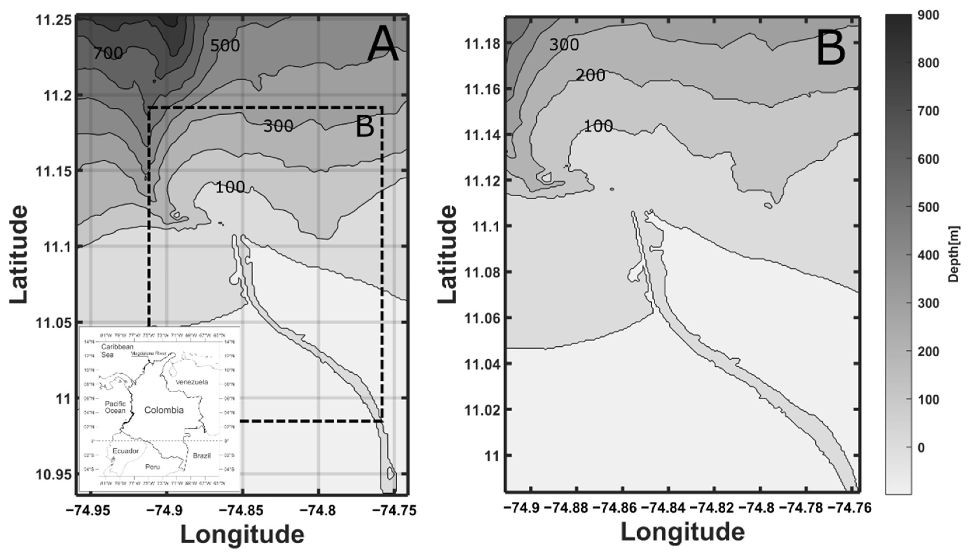
For the Magdalena River, a configuration nested on two levels was implemented. On the first level, the fluid was assumed to be barotropic, considering tidal forcing in the open boundary with the ocean, using data from the global tidal model FES2012 [14] and daily-averaged river discharges. Salinity at the ocean and river boundaries was assumed constant and equal to 37 g/kg and 0.1 g/kg, respectively. The calculation domain was represented by a regular rectangular mesh with Δx = Δy = 160 m covering a simulation domain of 851.35 km2, including 22 km of river channel, as shown in Figure 2A and using a time step Δt = 8 s (see Table 1 for the list of symbols). A more detailed second mesh was nested. In this mesh, the fluid was treated as baroclinic, also using a regular rectangular mesh with Δx = Δy = 80 m and vertical discretization on 37 z-coordinate layers, covering the simulation domain of 390.76 km2 shown in Figure 2B, and using a step Δt = 4 s. The boundary conditions of velocity, water level and salinity for the nested mesh are obtained from the results of the first general mesh. Wind forcing at the surface for both meshes was obtained from the Global Forecast System model (GFS) [15]. Winds were considered constant in space and variable in time with temporal resolution Δt = 3 h.
Vertical turbulence followed the General Ocean Turbulent Model (GOTM) with a k-ε closure model and Canuto’s stability function [16,17], whereas horizontal turbulence was described by Smagorinsky’s parameterisation. The model was calibrated and validated comparing modelling results with field measurements during low and high freshwater discharges. Calibration and validation revealed an optimal performance of the model with a horizontal eddy viscosity of 8 m2/s, a horizontal turbulent parameter of 0.4, a bottom roughness of 0.0025 m, and a wind drag coefficient of 0.001.

2.2. Evaluation of Power Consumed and Power Produced

For each possible combination of intake locations, it is necessary to evaluate the associated pumping requirements in terms of power, and the produced PRO power can be estimated based on the characteristics of the available flows. This is to be done as follows:
In a PRO process, freshwater (feed solution) and seawater (draw solution) are separated by a semi-permeable membrane that allows water flow from the feed side towards the draw side. This water flow (expressed per unit of surface) JW multiplied by the transmembrane pressure gradient ΔP gives the power produced WPRO
W P R O = J W · Δ P
In order to determine the water flux through the membrane, Touati’s general mass transport model can be employed, as it considers the concentration polarization on both sides of the membrane, internal and external [18]. Regarding the membrane, this model assumes that the active layer is on the draw side, and that its porous support is isotropic. Local thermal equilibrium and negligible thermal dispersion are assumed as well. As for the hydrodynamic conditions, the flow regime is turbulent and the process isobaric. The necessary parameters to apply this model are the membrane water permeability A, the salt permeability B, the transfer coefficients on the feed side kF and on the draw side kD (taken from [18], assuming negligible variation with temperature and viscosity in the operating range of values and hydrodynamic conditions), the solute resistivity K, and the osmotic pressures on the feed and draw sides πD and πF, respectively (see Equations (4) and (5)). A and B are chosen according to recent research results [19], considering average values of those obtained under similar conditions to the ones in this research.
J W = A [ ( π D + B A ( 1 + A Δ P J W ) ) · exp ( J W k D ) ( π F + B A ( 1 + A Δ P J W ) ) exp ( J W · K ) · exp ( J W k F ) Δ P ]
The salt flux Js can be calculated as follows:
J s = J W B A · β v H · R · T D ( 1 + A Δ P J W )
Moreover, πD and πF are calculated through the van’t Hoff equation (that is, ideal solutions are assumed):
π F = β v H · C F · R · T F
π D = β v H · C D · R · T D
where βvH is the van’t Hoff coefficient, which represents the number of ionic species in the solution dissociated from the original salt, βvH is approximated to 2.0, since most of the sea salt is sodium chloride, C depicts the molar concentration of each flow (mol/L), R is the universal gas constant and T the absolute temperature.
Osmotic pressures are dependent on the salinity; however, the salinities, and therefore πD and πF, do not remain constant throughout the process, they vary along the membrane, because a mass exchange is taking place. To correct this situation, several stages are considered using concentrations at intermediate locations of the membrane, estimating these concentrations at each of these intervals of the membrane [20]. Since the process is configured in countercurrent flow, iterative calculations are required to solve a loop of equations. A simple algorithm summarises the procedure: firstly, initial concentrations are estimated, and with them the salinity gradients at individual intervals can be calculated. Secondly, Touati’s model (Equation (2)) is applied to calculate JW in each stage, followed by the solution of mass balances at each section, obtaining newly calculated intermediate concentrations. Finally, the initial estimations and the calculated concentrations are compared: if the deviation does not satisfy a given tolerance, the procedure is repeated.
The salinity values of the feed and draw sides at the inlet can be taken from the salinity profile obtained with the hydrodynamic model described in Section 2.1. The temperature of both streams is also estimated with the model and used in the calculations.
The energy required for pumping water from the intake locations to the power plant is estimated considering friction losses, due to pumping from long distances, and the height difference (estimated at 2 m). Friction losses are estimated using Darcy’s equation, the most important variable being the distance. Pumping efficiency is also considered. The pressure drop of the draw circuit (Figure 1) is roughly estimated to be 0.5 bar, covered by a support pump; with a 99% efficiency of the pressure exchange system. Turbine efficiency is also considered when evaluating the net power, it is assumed to equal 85% [21]. Pretreatment power costs should also be considered; however, given the lack of state-of-the-art widely agreed-upon pretreatment technologies, and that these pretreatment costs would be similar in nearby locations, this energetic cost had to be excluded from the net power calculation in this case study [22,23,24]. Table 2 summarises some of the characteristics of the possible PRO power plant.

2.3. Selection of the Intakes Location

Once the power produced and consumed at different locations has been analysed, it is possible to deduce the most adequate location, based on the final power produced when subtracting the pumping power. There is a clear trade-off between the higher power production when the intakes are more separated, and the higher power costs associated to this distance. A compromise must be reached to optimize the net power production that can be achieved by comparing the results at different intake locations throughout the year.

3. Results and Discussion

The procedures described previously render the results presented in this section when applied to the case study of the Magdalena River.

3.1. Hydrodynamic Model

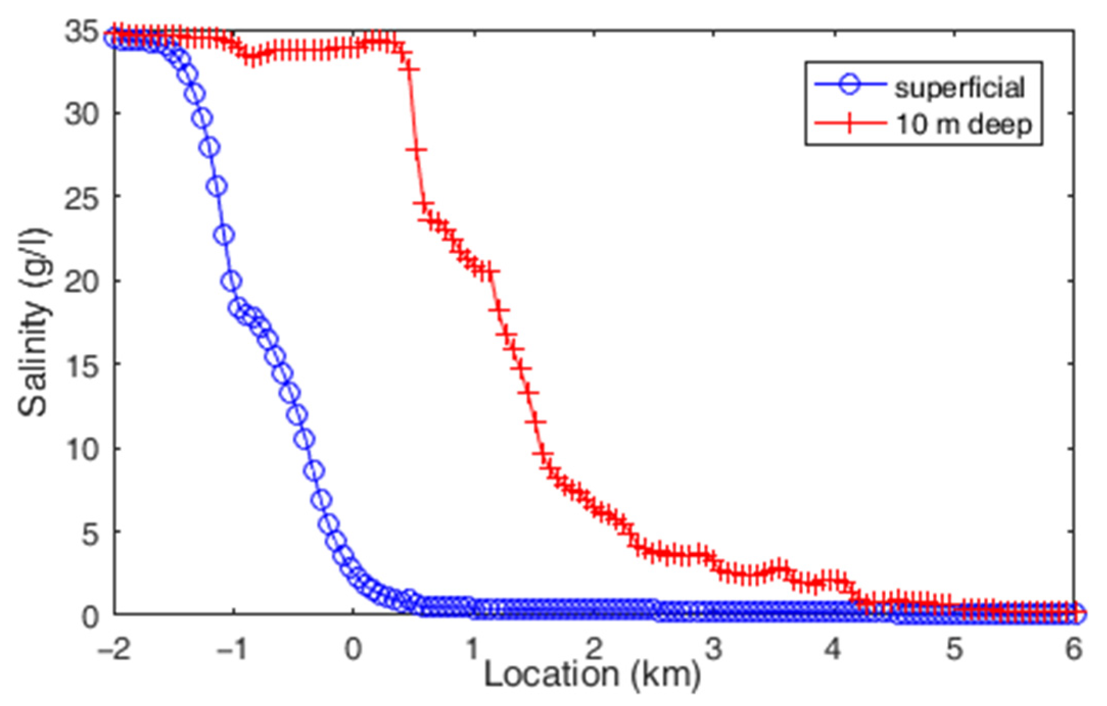
Figure 3 shows some results of the proposed hydrodynamic model: the mean salinity along the estuary during the dry season of an average climatic year is presented near the surface and at 10 m depth. In can be seen that near the surface the salinity remains close to zero until the end of the river mouth, where salinity increases rapidly as fresh water mixes with the ocean, reaching ocean salinities about 2 km seaward. On the other hand, at 10 m depth the water retains oceanic salinities up to 300 m inside the river channel, showing salt wedge intrusion and stratification. Further inside the river, close to the bottom, seawater starts mixing until reaching uniform freshwater conditions in the vertical profile about 4 km inside the river.
Based on Figure 3, the potential for a PRO plant can be seen, with extensive possibilities for combinations of feed and draw locations: draw water can be obtained at 10 m depth up to 1 km upriver; feed can be directly obtained from the surface from approximately 0.2 km.
Given that a map of concentrations has been provided by the model, another utility for it can be found when addressing the issue of outflows discharge. Suitable locations for outlet streams can be determined by an examination of their salinity and looking for a location with similar concentrations, so as not to disturb the salinity structure and the ecosystems at the estuary [25]. In this way, the incorporation of these streams should not affect the salinity profile significantly, neither should the intake streams at the Magdalena’s mouth because the river flow is much higher (7000 m3/s on average) [26]. However, this will vary in each case depending on the sizing of the power plant and the freshwater discharge of the river. This issue can be studied with the same hydrodynamic model, and is considered as future work.
Another important issue that has not been discussed yet is membrane fouling. At this point, it is assumed that the biological content in the water is constant in the riverbed, although higher organic content closer to the banks was observed. It would be possible to further analyse the presence of fouling materials in order to study membrane performance decay, and include this information in the hydrodynamic model.

3.2. PRO Power Production and Pumping Costs

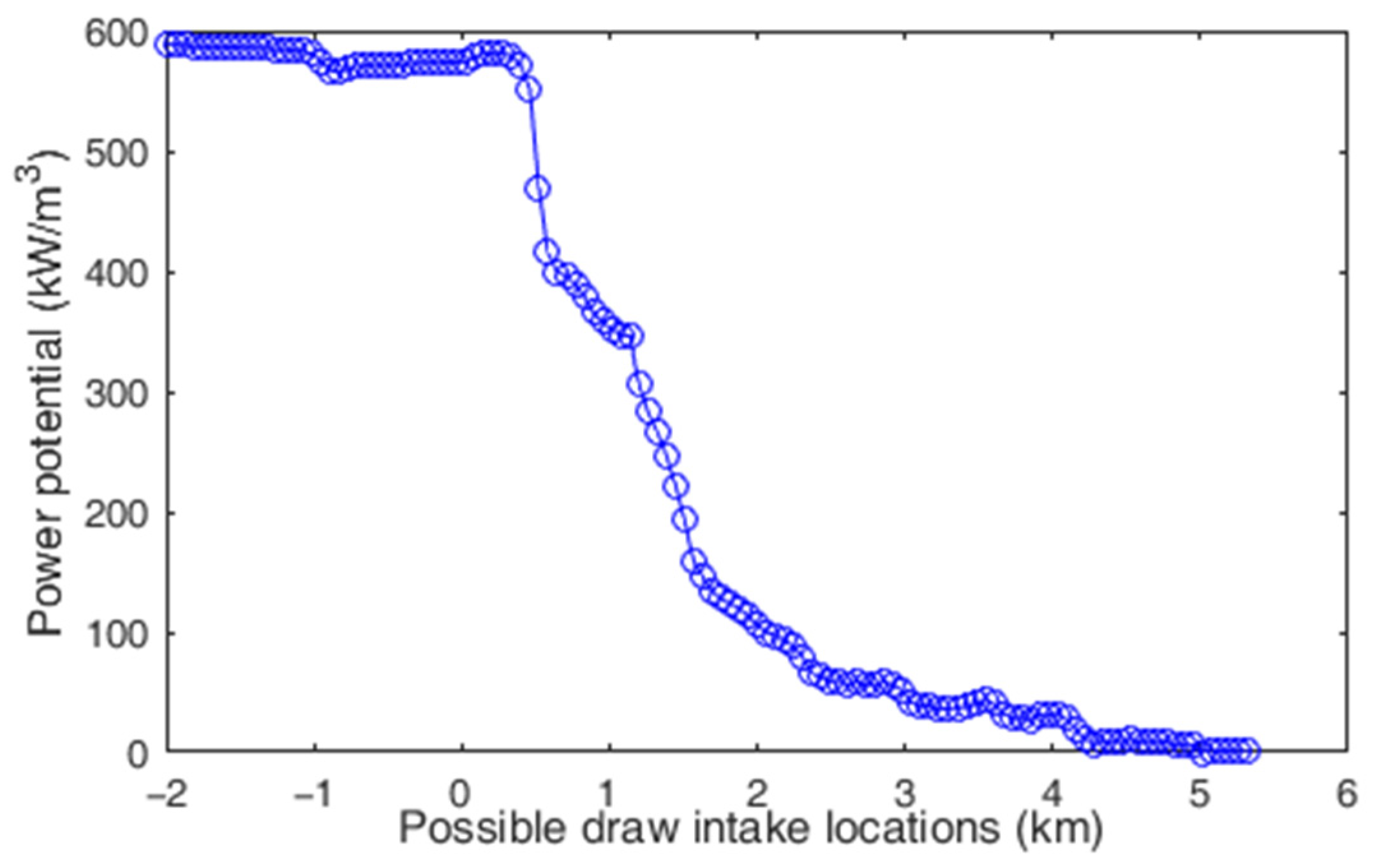
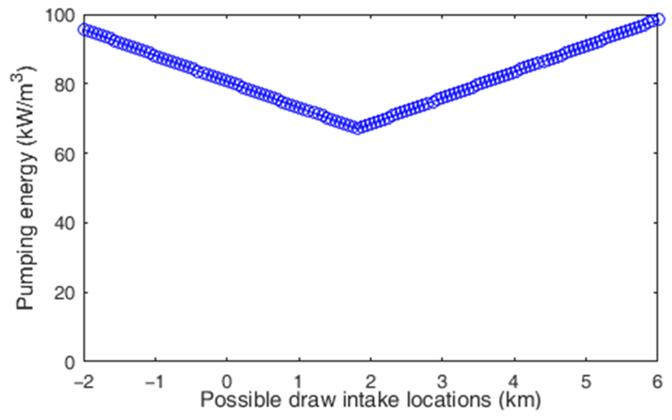
The calculation method described in Section 2 was applied to different combinations of water intakes. For instance, considering the superficial data at different distances as the feed, and the data close to the bottom at different distances as the draw, curves can be obtained to represent the different possible outcomes for the power production and to evaluate their potential. An example of what these curves look like is considered in a particular case: using a preliminary feed location fixed at 1.8 km, all possible intake points are used to calculate the power that a PRO plant would provide if draw water was taken from all these locations. Figure 4 is obtained based on Equations (1) and (2). For each of these locations, the pumping energy required can be evaluated using Darcy’s equation, as proposed. These pumping costs are presented in Figure 5.
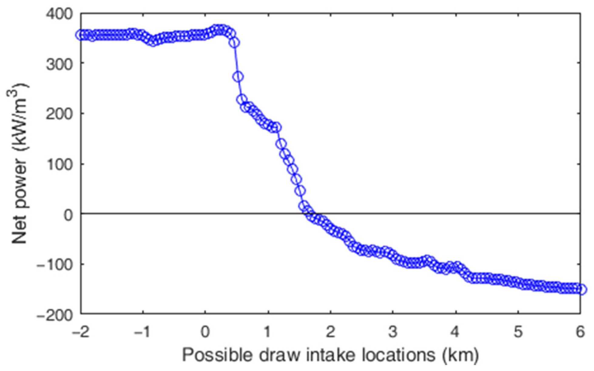
Comparing Figure 4 and Figure 5, the clear trade-off between the higher power production can be seen when the intakes are more separated, and the power costs associated to this distance. The net power productivity (Figure 6) can be calculated by subtracting Figure 5 values from Figure 4, after the turbine efficiency deduction. This net variable is much more useful and is the one that should guide any design decisions, because it shows where the potential can be best exploited.
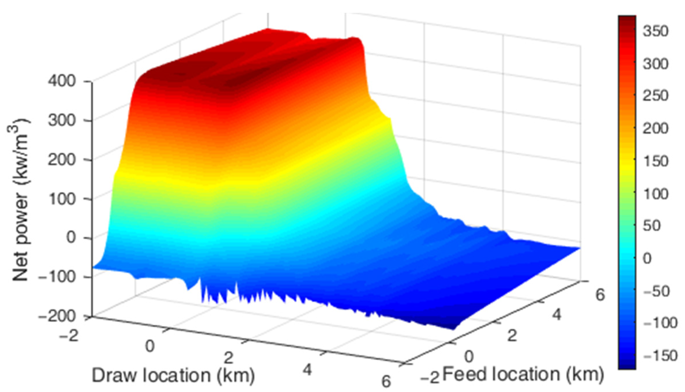
This procedure has been repeated for the set of feasible intake locations (for this, the estuary length was partitioned into 131 intervals). The numerical results make it possible to find some combinations of locations that lead to an increased overall efficiency, that is, the highest power after deducting pumping costs. Figure 7 shows a 3D representation of the available power for every combination of possible draw and intake location, after eliminating non-feasible pairs of data (those presenting a very large negative net power generation).
Figure 7 depicts the value of all the possible combinations of pairs of feed-draw locations. It presents a high net power region, identifiable by the red plateau, and a non-feasibility region presented in different shades of blue. The transition between both regions is abrupt due to the highly stratified conditions that take place in the Magdalena river mouth, where strong salinity gradients take place in short distances. The pattern of these results was expected, since Figure 3 already showed a limited interval of locations with high salinity gradient available.
The presence of this high net power delimited region, which overlaps with the high concentration gradient interval shown in Figure 3, suggests that the main driver for the feasibility of SGE generation at a given river mouth is precisely the salinity gradient. However, the optimum net SGE potential has been shown to be determined instead by the pumping distance, which is the decisive factor. This is because, at any river mouth, two locations can be found where salinity of the feed solution is close to zero, while the salinity of the draw solution is oceanic, but if both locations are too far from each other, the pumping energy will be higher than the power potential, which is limited.
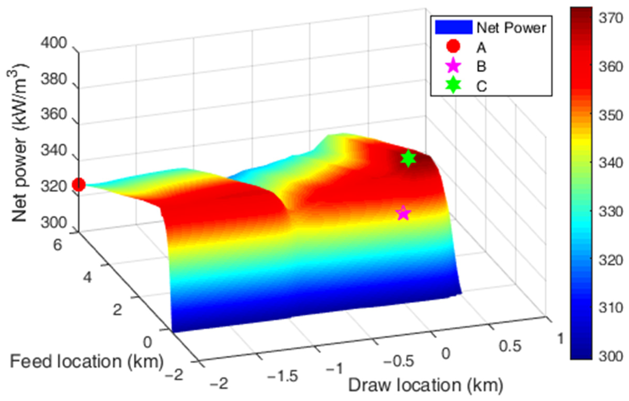
After analysing all the data represented in Figure 7, Table 3 summarises some of the most relevant scenarios: first (A), the combination which leads to the highest potential power; second (B), the highest power exploitable among all the locations with the lowest pumping demand (feed and draw intake in the same place); and third and most important, (C), the pair of feed and draw locations that presents the best efficiency.
Figure 8 shows a detail of the high net power data region from Figure 7, containing combinations A, B and C. The apparent red plateau from Figure 7 is not so smooth when looked at in more detail. A variability of up to 20% in the net power is shown in this representation.
Examination of Table 3 and Figure 8 shows that an improvement of up to 14% in the net power can be reached by choosing a location with a slightly lower potential. Additionally, it can be seen that the pumping distance is an important factor, but not the only one, hence scenario C provides an efficiency 7% higher than B.
The data region of high net power shown in Figure 7 is expected to vary with several factors. Variations in the river flowrate may alter the stratification and salinity profile, this would translate into a shrinking (higher flow rate) or widening (lower flow rate) of the plateau, along with a shift of its location within the distance locations map, because the length of the salinity intrusion in strongly stratified estuaries is very sensitive to the river discharge [27]. However, due to the stratification, water close to the surface will remain fresh while water close to the bottom will still be oceanic, even with very large discharge increments [28]. Salinity variations are expected in that situation, causing the high net power plateau to rise with increments of the salinity in the deeper layer, or fall with increments of the salinity in the superficial water, and vice versa.
A sensitivity analysis for the net power has been performed, considering variations in temperature and in salinity from the conditions obtained at best efficiency (case C in Table 3 and Figure 8). Five different scenarios have been considered: D, an increase of 1 °C of feed and draw temperature; E, a decrease of 1 °C in both temperatures; F, an increase of 1 g/L in the feed salinity; G, an increase of 1 g/L in the draw salinity; H, a decrease of 1 g/L in the draw salinity. Results from these disturbances are reflected in the net power, shown in Table 4.
These results show a small but substantial variation with temperature which responds in the same proportion to equal negative and positive variations, as expected from the linear dependence presented in Equations (4) and (5). A stronger dependence on salinity has been reported, especially in feed. Unlike the behaviour with temperature, salinity variation is highly non-linear: two perturbations of 1 g/L, positive in G and negative in H, lead to different percentage variations. The sensitivity to the feed salinity is more pronounced. This non-linear behaviour is expected from Touati’s model (Equation (2)).

4. Conclusions

A methodology has been presented in order to analyse the effect of intake locations in power produced by the membrane-based technology of Pressure-Retarded Osmosis in stratified river mouths. The methodology is based on the development of a multidisciplinary procedure that combines hydrodynamic models of the river mouth with models of the PRO process. This combination of models is then an effective way to predict the salinity structure of the river mouth, and as a result, to determine the net power production of the PRO as a function of the possible locations of the two water intakes. The results show the compromise between the desired lower intake distances and higher salinity gradient, for achieving higher power production. Here, we showed how important it is to find optimal locations in the planning and design of a potential power plant. The analysis proposed here found that the optimal locations provide 14% higher net power productivity, when comparing the set of optimal locations with the ones that give the maximum power.

Author Contributions

Methodology, J.M.S., O.Á.-S. and F.T.; software, J.M.S. and A.H.; validation, J.M.S., O.Á.-S. and A.H.; investigation, J.M.S.; resources, O.Á.-S. and F.T.; writing—original draft preparation, J.M.S.; writing—review and editing, J.M.S., O.Á.-S., A.H. and F.T.; visualization, J.M.S.; supervision, O.Á.-S. and F.T.; funding acquisition, J.M.S. and F.T. All authors have read and agreed to the published version of the manuscript.

Funding

Funded by Junta de Castilla y León with EU-FEDER funds (CLU-2017-09, VA232P18, UIC 225), and by Ministry of Science, Technology, and Innovation of Colombia (MINCIENCIAS, contract 145-2019).

Institutional Review Board Statement

Not applicable.

Data Availability Statement

Conflicts of Interest

The authors declare no conflict of interest. The funders had no role in the design of the study; in the collection, analyses, or interpretation of data; in the writing of the manuscript, or in the decision to publish the results.

References

  1. Gross, M.; Rüdiger, M. Renewable Energies; Routledge: London, UK, 2014. [Google Scholar]
  2. Østergaard, P.A.; Duic, N.; Noorollahi, Y.; Mikulcic, H.; Kalogirou, S. Sustainable development using renewable energy technology. Renew. Energy 2020, 146, 2430–2437. [Google Scholar] [CrossRef]
  3. Twidell, J. Tony Weir. In Renewable Energy Resources; Routledge: London, UK, 2015. [Google Scholar]
  4. Halkos, G.E.; Eleni-Christina, G. Reviewing Usage, Potentials, and Limitations of Renewable Energy Sources. Energies 2020, 13, 2906. [Google Scholar] [CrossRef]
  5. Hussain, A.; Syed, M.A.; Muhammad, A. Emerging renewable and sustainable energy technologies: State of the art. Renew. Sustain. Energy Rev. 2017, 71, 12–28. [Google Scholar] [CrossRef]
  6. Micale, G.; Cipollina, A.; Tamburini, A. Salinity gradient energy. In Sustainable Energy from Salinity Gradients; Woodhead Publishing: Sawston, UK, 2016; pp. 1–17. [Google Scholar]
  7. Touati, K.; Tadeo, F.; Kim, J.H.; Silva, O.A.A.; Chae, S.H. Pressure Retarded Osmosis: Renewable Energy Generation and Recovery; Academic Press: Cambridge, MA, USA, 2017. [Google Scholar]
  8. Alvarez-Silva, A.; Osorio, A.F.; Winter, C. Practical global salinity gradient energy potential. Renew. Sustain. Energy Rev. 2016, 60, 1387–1395. [Google Scholar] [CrossRef]
  9. Sandbach, S.D.; Nicholas, A.P.; Ashworth, P.J.; Best, J.L.; Keevil, C.E.; Parsons, D.R.; Simpson, C.J. Hydrodynamic modelling of tidal-fluvial flows in a large river estuary. Estuar. Coast. Shelf Sci. 2018, 212, 176–188. [Google Scholar] [CrossRef]
  10. Panchenko, E.; Max, L.; Serafima, L. Hydrodynamic modelling of the Onega River tidal estuary. E3S Web Conf. 2020, 163, 01-008. [Google Scholar] [CrossRef]
  11. Restrepo, J.C.; Ortiz, J.C.; Pierini, J. Freshwater discharge into the Caribbean Sea from the rivers of Northwestern South America (Colombia): Magnitude, variability and recent changes. J. Hydrol. 2014, 509, 266–281. [Google Scholar] [CrossRef]
  12. Leitao, P.; Mateus, M.; Braunschweig, L.; Fernandes, L.; Neves, R. Modelling Coastal Systems: The MOHID Water Numerical Lab, Perspectives on Integrated Coastal Zone Management in South America; IST Press: Lisboa, Portugal, 2008. [Google Scholar]
  13. Martins, F.; Leitao, P.; Silva, A.; Neves, R. 3D modelling in the Sado estuary using a new generic vertical discretization approach. Oceanol. Acta 2001, 24, 51–62. [Google Scholar] [CrossRef] [Green Version]
  14. Available online: https://www.aviso.altimetry.fr/en/data/products/auxiliary-products/global-tide-fes/description-fes2012.html (accessed on 16 April 2021).
  15. Available online: https://www.ncdc.noaa.gov/data-access/model-data/model-datasets/global-forcast-system-gfs (accessed on 16 April 2021).
  16. Skote, M. Studies of Turbulent Boundary Layer Flow through Direct Numerical Simulation; Technical Report; Royal Institute of Technology, Department of Mechanics: Stockholm, Sweden, 2001. [Google Scholar]
  17. Canuto, V.M.; Howard, A.; Cheng, Y.; Dubovikov, M.S. Ocean Turbulence. Part I: One-point closure model momentum and heat vertical diffusivities. J. Phys. Oceanogr. 2001, 31, 1413–1426. [Google Scholar] [CrossRef]
  18. Touati, K.; Hänel, C.; Tadeo, F.; Schiestel, T. Effect of the feed and draw solution temperatures on PRO performance: Theoretical and experimental study. Desalination 2015, 365, 182–195. [Google Scholar] [CrossRef]
  19. Gonzales, R.R.; Abdel-Wahab, A.; Adham, S.; Dong, S.H.; Phuntsho, S.; Suwaileh, W.; Hilalf, N.; Shon, H.K. Salinity gradient energy generation by pressure retarded osmosis: A review. Desalination 2021, 500, 114841. [Google Scholar] [CrossRef]
  20. Salamanca, J.M.; Álvarez-Silva, O.; Tadeo, F. Potential and analysis of an osmotic power plant in the Magdalena River using experimental field-data. Energy 2019, 180, 548–555. [Google Scholar] [CrossRef] [Green Version]
  21. Seme, S.; Sredensk, K.; Praunseis, Z.; Stumberger, B.; Hadziselimovic, M. Optimal price of electricity of solar power plants and small hydro power plants–Technical and economical part of investments. Energy 2018, 157, 87–95. [Google Scholar] [CrossRef]
  22. Abbasi-Garravand, E.; Catherine, N.; Mulligan, C.B.; Laflamme, G.C. Role of two different pretreatment methods in osmotic power (salinity gradient energy) generation. Renew. Energy 2016, 96, 98–119. [Google Scholar] [CrossRef]
  23. Roldan-Carvajal, M.; Vallejo-Castaño, S.; Álvarez-Silva, O.; Bernal-García, S.; Arango-Aramburo, S.; Sánchez-Sáenz, C.I.; Osorio, A.F. Salinity gradient power by reverse electrodialysis: A multidisciplinary assessment in the Colombian context. Desalination 2021, 503, 114933. [Google Scholar] [CrossRef]
  24. Alvarez-Silva, O.; Maturana, A.Y.; Pacheco-Bustos, C.A.; Osorio, A.F. Effects of water pretreatment on the extractable salinity gradient energy at river mouths: The case of Magdalena River, Caribbean Sea. J. Ocean Eng. Marine Energy 2019, 5, 227–240. [Google Scholar] [CrossRef]
  25. Ortega, S.; Stenzel, P.; Alvarez-Silva, O.; Osorio, A.F. Site-specific potential analysis for pressure retarded osmosis (PRO) power plants–The León River example. Renew. Energy 2014, 68, 466–474. [Google Scholar] [CrossRef]
  26. Alvarez-Silva, A.; Winter, C.; Osorio, A.F. Salinity gradient energy at river mouths. Environ. Sci. J. Technol. Lett. 2014, 1, 410–415. [Google Scholar] [CrossRef]
  27. Geyer, W.R.; Ralston, D.K. The dynamics of strongly stratified estuaries. In Treatise on Estuarine and Coastal Science; Elsevier: Amsterdam, The Netherlands, 2011; pp. 37–52. [Google Scholar]
  28. Ospino, S.; Restrepo, J.C.; Otero, L.; Pierini, J.; Alvarez-Silva, O. Saltwater Intrusion into a River with High Fluvial Discharge: A Microtidal Estuary of the Magdalena River, Colombia. J. Coast. Res. 2018, 34, 1273–1288. [Google Scholar]
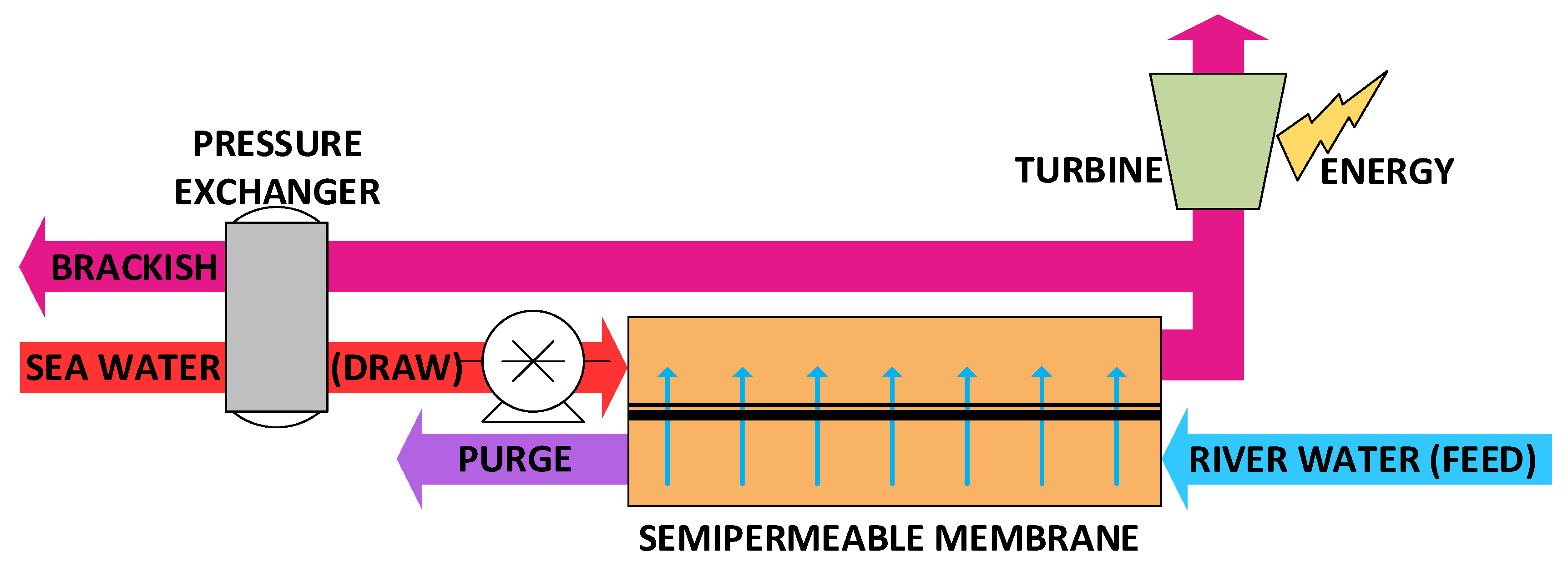
Figure 1. Block diagram of a standard PRO process.
Water 13 01133 g001
Figure 2. (A) Location of the study zone and domain of the first mesh of the model. The dashed square shows the simulation domain of the nested and more refined model. (B) Details of the covered area and bathymetry of the nested model.
Water 13 01133 g002
Figure 3. Salinity profile estimated by the hydrodynamic model for the final stretch of the Magdalena river. The horizontal axis indicates distance in km from the end of the river’s channel, with positive distances upstream of the river and negative distances seaward.
Water 13 01133 g003
Figure 4. Power production dependence with the location of the draw water for a given feed location at 1.8 km.
Water 13 01133 g004
Figure 5. Pumping energy required for draw water taken from different locations for a given feed intake point at 1.8 km (horizontal axis: distance from the end of the river’s channel, with positive distances upstream).
Water 13 01133 g005
Figure 6. Pumping energy required for draw water taken from different locations (horizontal axis: distance from the end of the river’s channel, with positive distances upstream).
Water 13 01133 g006
Figure 7. Available net power after subtracting pumping energy for each combination of pairs of data (feed intake distance-draw intake distance).
Water 13 01133 g007
Figure 8. Detail of the highest net power data region from Figure 7, with relevant scenarios A, B and C from Table 3.
Water 13 01133 g008
Table 1. List of symbols.
SymbolVariableUnits
AWater permeabilitym/s·Pa
BSalt permeabilitym/s
CDSalinity in draw stream mol/m3
CFSalinity in feed streammol/m3
JWTransmembrane flow densitym/s
JsTransmembrane salt flow densitymol/m2·s
KSolute resistivitys/m
kDMass transfer coefficient (membrane draw side)m/s
kFMass transfer coefficient (membrane feed side)m/s
RUniversal ideal gas constantJ/mol·K
TDDraw temperatureK
TFFeed temperatureK
WPROPower density from pressure retarded osmosisW/m2
βvHvan’t Hoff coefficient-
ΔxHydrodynamic model mesh widthm
ΔyHydrodynamic model mesh lengthm
ΔPDraw external pressurePa
ΔtHydrodynamic model time steps
πDOsmotic pressure of draw streamPa
πFOsmotic pressure of feed streamPa
Table 2. Membrane parameters, operation variables and performance results.
Water permeability A1.1 × 10−11 m3/m2·s·Pa
Salt permeability B1.2 × 10−7 m3/m2·s
Average osmotic gradient19.7 bar
Membrane area requirement1.5 × 105 m2/m3feed/s
Average power densityUp to 6.4 W/m2
Table 3. Comparison between relevant combinations of feed and draw locations.
A: Highest PowerB: Lowest PumpingC: Best Efficiency
Feed intake (km)6.00.030.58
Draw intake (km)−2.00.030.15
Relative Distance (km)8.000.43
Feed mean salinity (g/L)0.111.90.28
Draw mean salinity (g/L)34.833.934.3
Gross power potential (kW/m3)593546579
Pumping power (kW/m3)166106109
Net power (kW/m3)327347373
Table 4. Sensitivity analysis for the net power.
ScenarioBase CaseD: +1 °CE: −1 °CF: +1 g/L FeedG: +1 g/L DrawH: −1 g/L Draw
Net power (kW/m3)373375371314388353
% variation +0.6%−0.6%−15.8%+3.9%−5.3%
Publisher’s Note: MDPI stays neutral with regard to jurisdictional claims in published maps and institutional affiliations.