1. Introduction
An environmental impact assessment (EIA) is an important process, which is applied prior to approving the implementation of an investment plan [
1]. An EIA involves detailed examination of the likely and foreseeable impacts of the proposed activity on the environment and on the health of the population [
2]. An EIA is based on detailed analysis of the expected and other potential impacts on individual components of the environment and the population, such as the water, soil, air, climate, flora and fauna, including the landscape and cultural and historical heritage [
3]. In other words, an EIA is an ancillary planning activity aims to identify, predict and assess the impacts of the proposed actions and development projects on the environment and especially the population [
4,
5,
6].
Numerous EIA approaches have been designed as tools for identifying, predicting and assessing the impacts of a proposed project and for preparing an Environmental Impact Statement [
7,
8]. In the process of prioritizing investment projects, an EIA has become an important tool for promoting the principles of sustainable development and the best available technology [
9]. At present, continuous improvements, with new, more efficient and effective methodological and legislative instruments and procedures for environmental assessment, as well as management, are being researched. Klemeš and Kravanja [
10] applied segmented pinch analysis and mathematical programming for saving energy. Wang et al. [
11] used segmented pinch analysis for environmental risk management and Jia et al. [
12] applied segmented pinch analysis for waste management. Geographical information systems (GIS) and multicriteria analysis (MCA) methods are very popular and useful tools in environmental assessment and management. Wang et al. [
13] used these methods for flood risk assessment in the Dongting Lake Region in Central China; Romanescu [
14] applied MCA methods for flood vulnerability assessment at Marginea village in north-east Romania; Blišťanová [
15] applied GIS and MCA methods for flood vulnerability assessment in the Bodva stream catchment in south-east Slovakia; Zeleňáková et al. [
16] assessed flood damages based on BIM; and Pintilie et al. [
17] applied 2D streamflow hydraulic modelling to improve urban flood hazard maps. Risk analysis (RA) has also become an important tool for decision-making and management activities in recent years [
18]. RA is currently widely used for predicting the dangers arising from various stressors: physical and chemical (for example, natural disasters, climate change, pollution and contaminants in food and water); biological (human, plant and animal pathogens, pests affecting plants and animals and invasive species); social and economic (unemployment, financial losses and public safety, including the risk of terrorism); construction and engineering (building safety, fire safety and military applications); and trade (project activities, insurance, litigation and credit) [
19].
This paper deals with the selection of the best alternative of the proposed flood mitigation measure for the assessed study area—Veľká Lúka municipality—based on environmental impact assessments of the proposed alternatives using the risk analysis method. The Lukavica stream flowing through the built-up area of Veľká Lúka represents a permanent threat of flooding in the village. In recent years there have been extensive consequences of floods, especially for the environment and for the property of residents and the village. For this reason, it is necessary to increase the flood protection of the environment and the village inhabitants. Increased flood protection in Veľká Lúka can be achieved by various measures ranging from implementing effective technical measures to increasing the overall retention capacity of the landscape itself. The purpose of the proposed activity, in this case building flood protection structures, is to control the runoff conditions in order to increase protection against flooding in the village.
The paper proposes an original innovative methodology for a selection of the best alternative of flood protection measure in the areas endangered by floods.
2. Materials and Methods
The village of Veľká Lúka and its surrounding area (near the town of Zvolen in central Slovakia) has experienced several cases of flooding in the past due to overflowing water from the Lukavica stream. This problem has become more serious in recent years because several buildings have been constructed in the village along the Lukavica stream in the immediate vicinity of the flood plain area and other builders are demanding a solution to the flood risk in the local area. The current situation is complicated by the fact that there is no space in the village’s built-up area to increase the discharge capacity of the stream. The Lukavica stream bed is not able to cope with increased discharges at values of Q2 (2-year return period) up to Q5 (5-year return period), not to mention Q10 (10-year return period) at 28 m3·s−1.
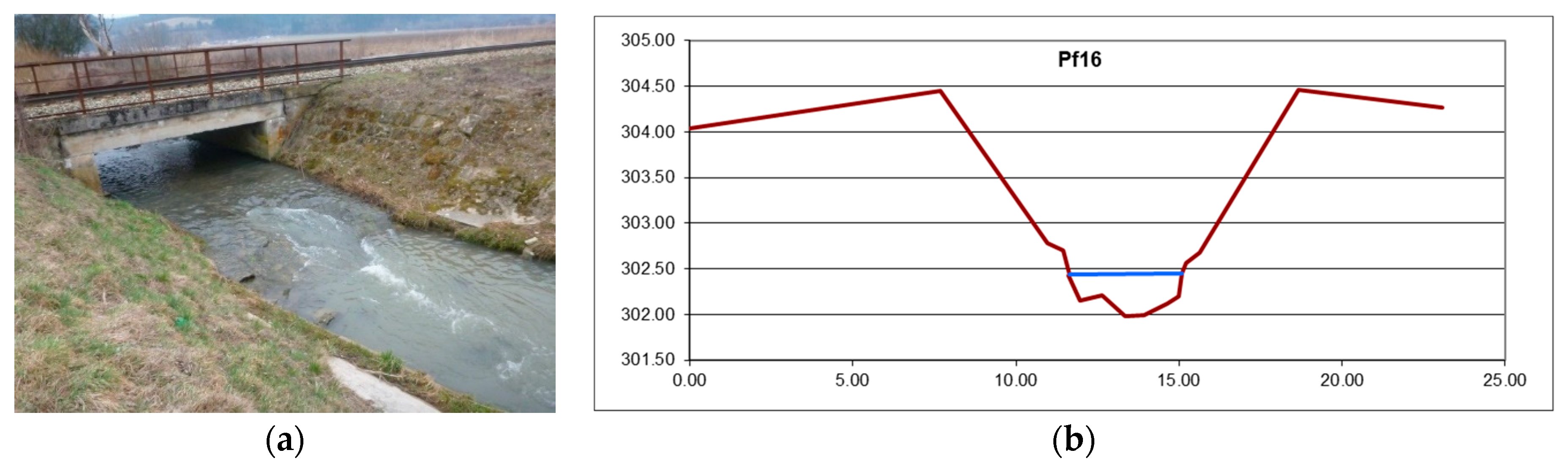
Another significant problem is the crossing of the Lukavica stream by the Zvolen to Banská Bystrica railway (
Figure 1). The capacity of the railway bridge culvert is restricted, but as it turned out in studying the problem, this was not decisive. Due to the fact that no data on the stream bed morphology were available, the research team measured 38 cross-sections of the stream, including structures located between the confluence of Lukavica and Hron up to the assumed profile of the proposed detention reservoir. These data served as the basis for creating a mathematical model of open channel flow in steady and unsteady conditions. With the help of this model, it was possible to determine the capacity-critical points on the Lukavica stream in the Veľká Lúka built-up area and to design appropriate flood protection measures.
2.1. Study Area Description
The location of the proposed activity is in the cadastral territory of the village Veľká Lúka, as shown in
Figure 1.
The catchment area of the Lukavica stream itself is not extensive. Its area to the profile just upstream of the village of Veľká Lúka is about 34 km2. The Lukavica stream itself is a left tributary of the Hron River north of the town of Sliač; it is 14 km long and it is a third order stream. It rises near the village of Horná Mičiná at an altitude of 490 m asl. and flows down into the Zvolen (Sliač) Basin through the villages of Dolná Mičiná, Lukavica and Veľká Lúka in the districts of Banská Bystrica and Zvolen. Its most important tributaries are the Jasenica (right-hand tributary at river km 7.420) and Samporský stream (left-hand tributary at river km 4.900). The following structures are located along the stream: a ford and two road bridges in the central part of Veľká Lúka, a railway bridge (with culvert) in the lower part of the village and a bridge leading to the adjacent fields.
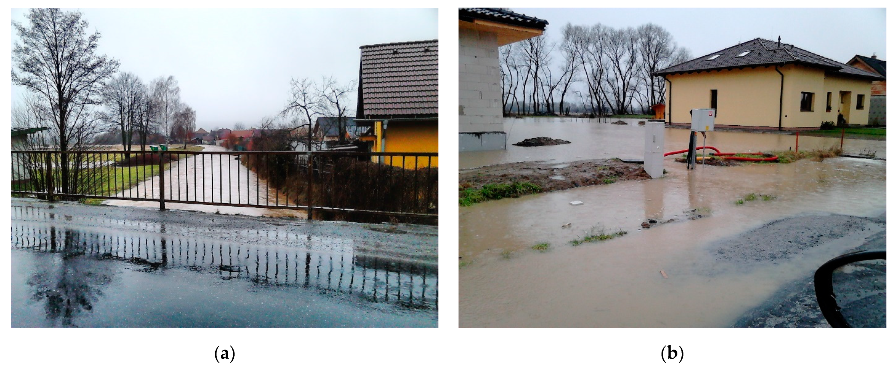
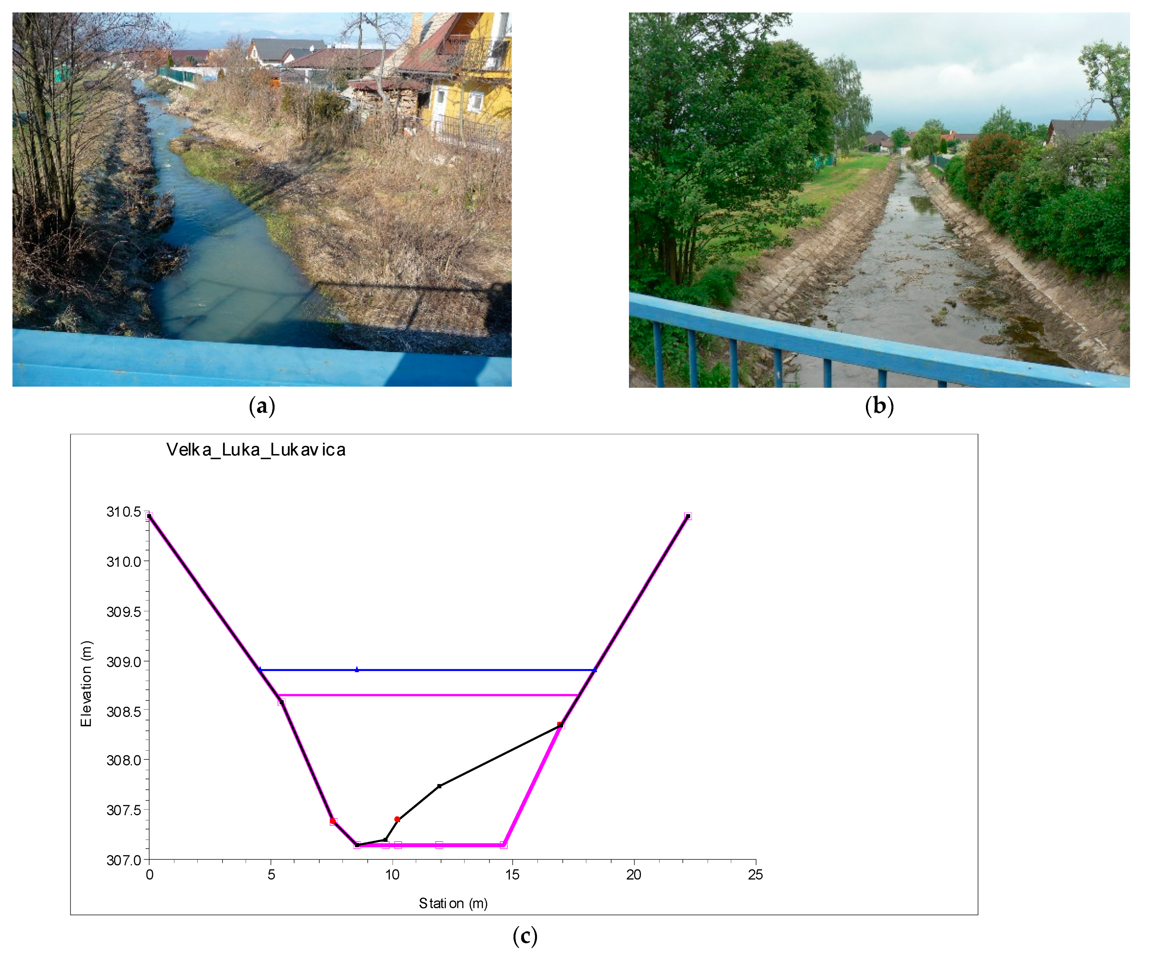
Despite the fact that the Lukavica stream catchment area is not large, the occurrence of flood situations has manifested itself in the past, as shown in some real photos shown in
Figure 2.
The Lukavica stream regulation carried out in the 1960s involved only a small part of the village and its capacity is currently insufficient. This is also obvious from the last higher flood situations, which occurred in 2009 (25th December), 2013 (13th March) and 2016 (10th February), when the water levels reached the 2nd and 3rd (highest) degrees of flood activity.
From its mouth (confluence with the Hron, river km 0.000) to the reinforced concrete bridge of the field road (river km 0.750), the Lukavica stream bed has an irregular shape with a variable bottom width of 3–6 m, varying bank slopes and a height of 2–3 m. The survey revealed that the bank slopes of the stream bed are reinforced with panels supported by concrete footings. However, the panels are densely overgrown with bushes and trees, and at the confluence of the Lukavica and Hron streams, the panels are considerably displaced, and the original shape of the reinforced stream bed is deformed. The appearance of the panels above the confluence of Lukavica and Hron can be seen in
Figure 3 (right) [
20].
From the reinforced concrete bridge (river km 0.750) to the railway bridge (river km 1.185), the stream bed has a trapezoidal shape with a width of about 4 m at the bottom, bank slopes of 1: 2.5 and height of about 2 m. Stream regulation has been carried out in this part and the stream bed is relatively clean.
From the railway bridge (river km 1.185) to the old non-functional diversion structure (river km 2.031), the cross-section has a variable bottom width of 1.5 to 4.5 m. The stream bed itself is quite narrow and there is dense vegetation growth along the banks, which significantly reduces the flow area at higher water levels (
Figure 3, left). In this part, on the right side of the stream, there are new buildings located in the stream’s inundation zone and the inhabitants of the adjacent area report frequent flooding of their land. Due to the planned construction of family houses on the left side of the stream, this section is the most problematic and the most critical in terms of the capacity of the Lukavica stream bed through the village.
The stream bed in the section between the two road bridges (approx. river km 2.220 —river km 2.340) has a relatively large bottom width (8–10 m), bank slopes of about 1: 1.5 and a height of 2–3 m. The stream bed is considerably loaded with sediments, the thickness of which reaches up to 70 cm in some parts.
2.2. Field Measurements
Fresh and current data were needed, which were obtained by means of a terrestrial geodetic survey of the stream bed (cross-sections in the range river km 0.000–3.455), followed by a detailed survey of the floodplain that would be created by building a detention reservoir for retaining the designated flood wave. The measurements were performed using the coordinate system of the Unified Trigonometric Cadastral Network (S-JTSK) and the Baltic Vertical Datum—After Adjustment (
Figure 4).
Subsequently, geodetic measurements of the area have been identified for the detention reservoir, which are taken as the basis for the digital terrain model. The measurements were made at 23 temporarily stabilized auxiliary measurement points, the coordinates of which were determined in the S-JTSK co-ordinated system using global navigational satellite systems (GNSS) via the Slovak real-time positioning service (SKPOS). The heights of the point field were also determined using SKPOS in the Baltic Vertical Datum—After Adjustment elevation system. A total of 3451 points were surveyed (
Figure 5), from which a digital terrain model in the form of a triangulated irregular network (TIN) was created. From this model, the storage elevation curve (V = f (H)) was determined for the chosen profile of the detention reservoir, the proposed height of the dam and dimensions of the outlet culvert [
21].
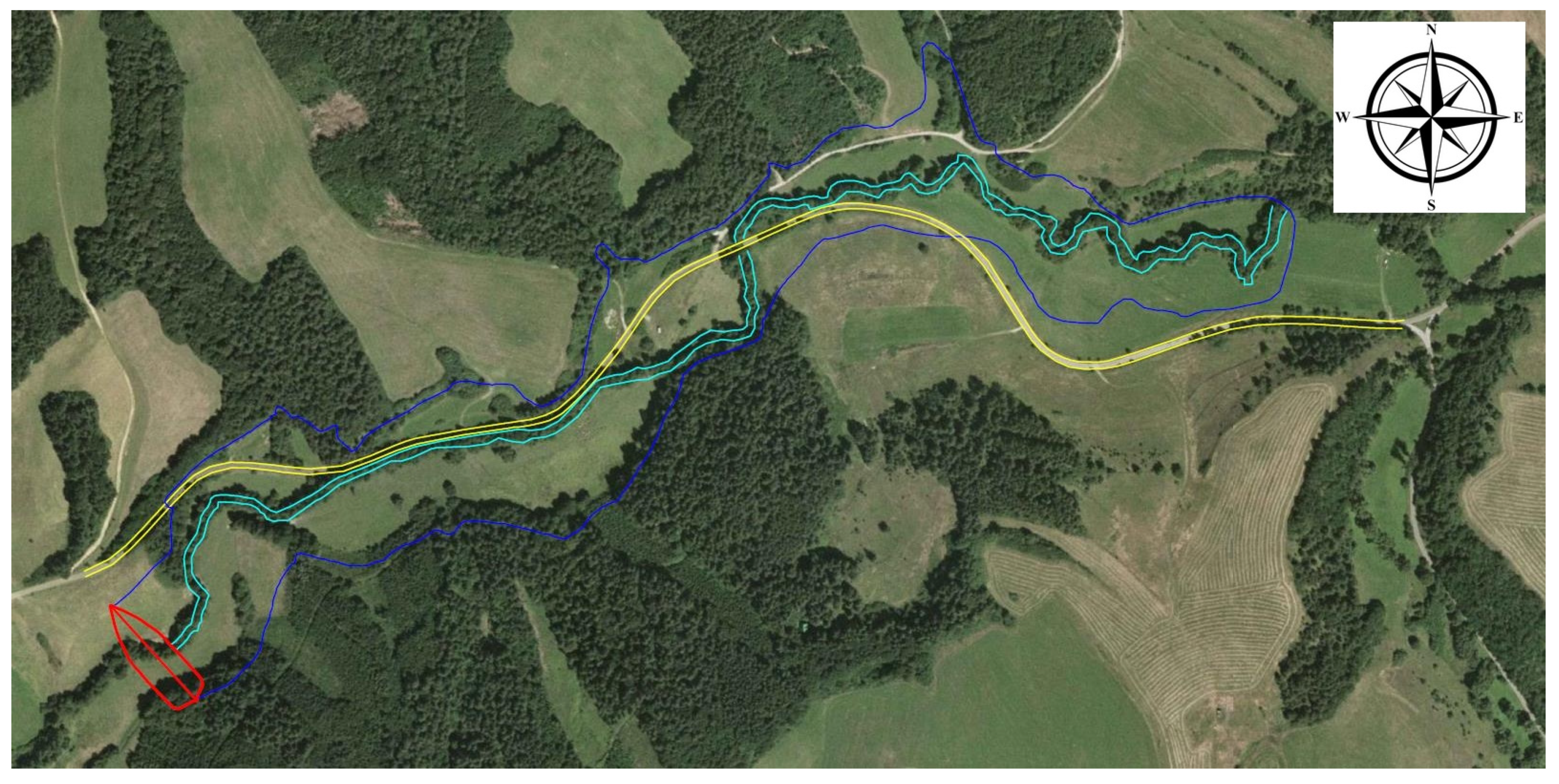
From the digital terrain model, the storage elevation curves were developed for the two chosen profiles. Profile 1 was selected from the previous flood protection study in this locality prepared by the Slovak Water Management Company (SWMC), Banská Bystrica branch. Profile 2 was specified on the basis of field reconnaissance, because it appeared to be more advantageous in terms of the retention volume of the proposed detention reservoir. Both profiles are located above the village of Veľká Lúka in such a way that the proposed dam location at the designated height of about 10 m does not interfere with the road leading through the valley between the villages of Lukavica and Veľká Lúka (
Figure 6).
The flooded area curves for these profiles were first laid out, developed from the digital terrain model with a contour interval spacing of 0.25 m, from which the storage elevation curves were subsequently obtained by calculation. The assumption from the field survey was correct, because at Profile 1, with the proposed height of the dam set at 10 m, the retention volume would come to 618,000 m3, and at Profile 2 the volume would attain 633,000 m3.
2.3. Hydrological Data
After evaluation of all available data on the morphology of the Lukavica stream and the surrounding terrain, the procedure continued with the analysis of hydrological data. The data provided by SWMC showed that the long-term average discharge of the Lukavica stream in the Veľká Lúka reach is 0.268 m
3·s
−1.
Table 1 shows the day (M) and year (N) discharges of the Lukavica stream in the reach at river km 2.06 (Veľká Lúka), with a basin area of approximately 36 km
2. These data were set by the Slovak Hydrometeorogical Institute (SHMI) in 1997 and were derived for the natural runoff regime in the reference period 1931–1980. Data were checked and are still the same as no big changes had been made in the territory in the last decades.
SHMI also prepared the course of the designated flood wave at the 100-year discharge Q
100 = 49 m
3·s
−1. This value does not correspond to the value for Q
100 from
Table 1; this is due to the fact it was calculated for the profile on the Lukavica stream selected for the proposed detention reservoir at river km 3.455 (profile 1,
Figure 6). According to the SHMI, the volume of the flood wave was set at 1.8 mil·m
3, with a total flood duration t
c = 20 h 25 min (increasing time t
st = 8 h 10 min and decreasing time t
kl = 12 h 15 min).
Another possible alternative solution was to locate the detention reservoir further upstream from Veľká Lúka at river km 7.10, where a smaller reservoir volume would be enough to retain the designated flood. Hydrological data provided by SHMI related to this profile on the Lukavica stream were as follows: culmination of the designated flood wave should occur after about 6 h at 100-year flow Q100 = 39.5 m3·s−1, with the flood wave volume set at 1.02 mil·m3.
2.4. Mathematical Modelling of the Water Level Regime of the Lukavica Stream
The one-dimensional mathematical model developed by the US Army Corps of Engineers, Hydrologic Engineering Center’s Stream Analysis System (HEC-RAS 5.0.7) [
22] was used to determine the water level regime of the Lukavica stream in the study area (
Figure 7), with the planned flood protection measures.
The geometry of the studied sections of the Lukavica stream were schematized using cross-sections generated on the basis of field measurements with stream sections according to the survey (river km 0.000 is the confluence of Lukavica and Hron). For calibration purposes, simultaneously with the geodetic survey the water level was measured at each cross section and values of discharge were also measured for the three reference profiles. Cross sections marked in
Figure 7 were used for hydraulic modelling in HEC-RAS.
With regard to the solution of the water level regime, several alternatives of the mathematical model were created:
- -
model of current state according to measurements;
- -
model without sediments in the built-up area of the village;
- -
model with installation of small dikes in the built-up area of the village and stream bed regulation downstream from the proposed detention reservoir.
Simulations of the water level regimes in each model were set for steady non-uniform flow in a mixed regime due to the longitudinal conditions of the stream bed, because changes in the flow regime were expected (subcritical, supercritical).
Boundary conditions were entered:
- -
discharge;
- -
normal depth.
The simulation results predicted the water level course for each model in the study area. Water level regime means the water level course in the given section within the entered boundary conditions, whereby it reveals problem areas where overflowing can occur. Based on them, measures were proposed to increase the capacity of the stream bed, and they also served as a basis for determining the amount of outflow from the proposed detention reservoir above the village of Veľká Lúka.
Model of Current State According to Field Measurements
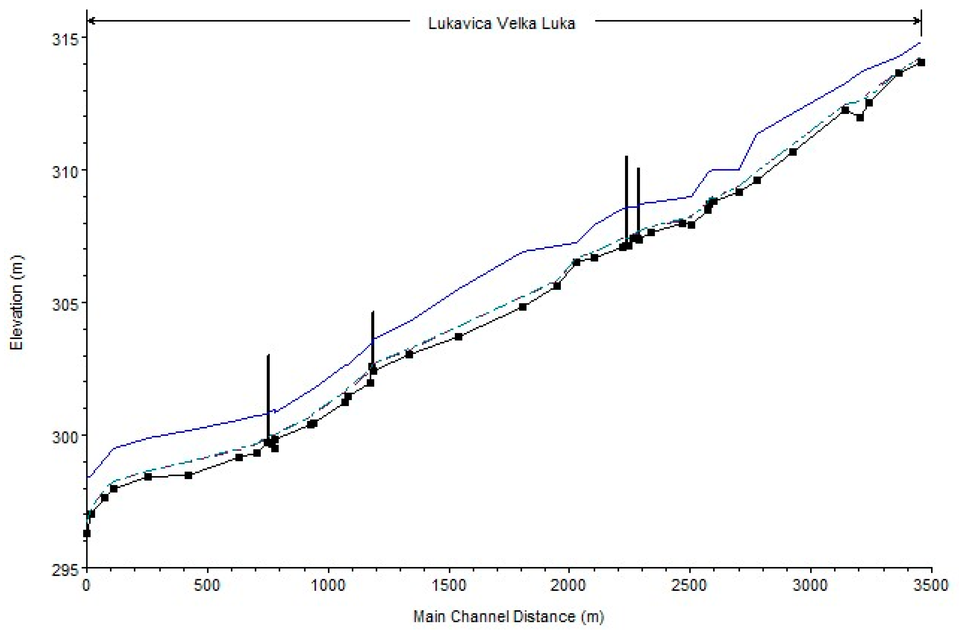
The cross section in the mathematical model was identical to the survey one, starting at km 0.000 (confluence of Lukavica and Hron) and ending at river km 3.455 (approximately the profile of the planned detention reservoir dam). The cross-sections were entered into the model in an upstream sequence, i.e., the first profile in the model is at river km 0.000 (PF 1) and the study area ends at river km 3.455 (PF 38).
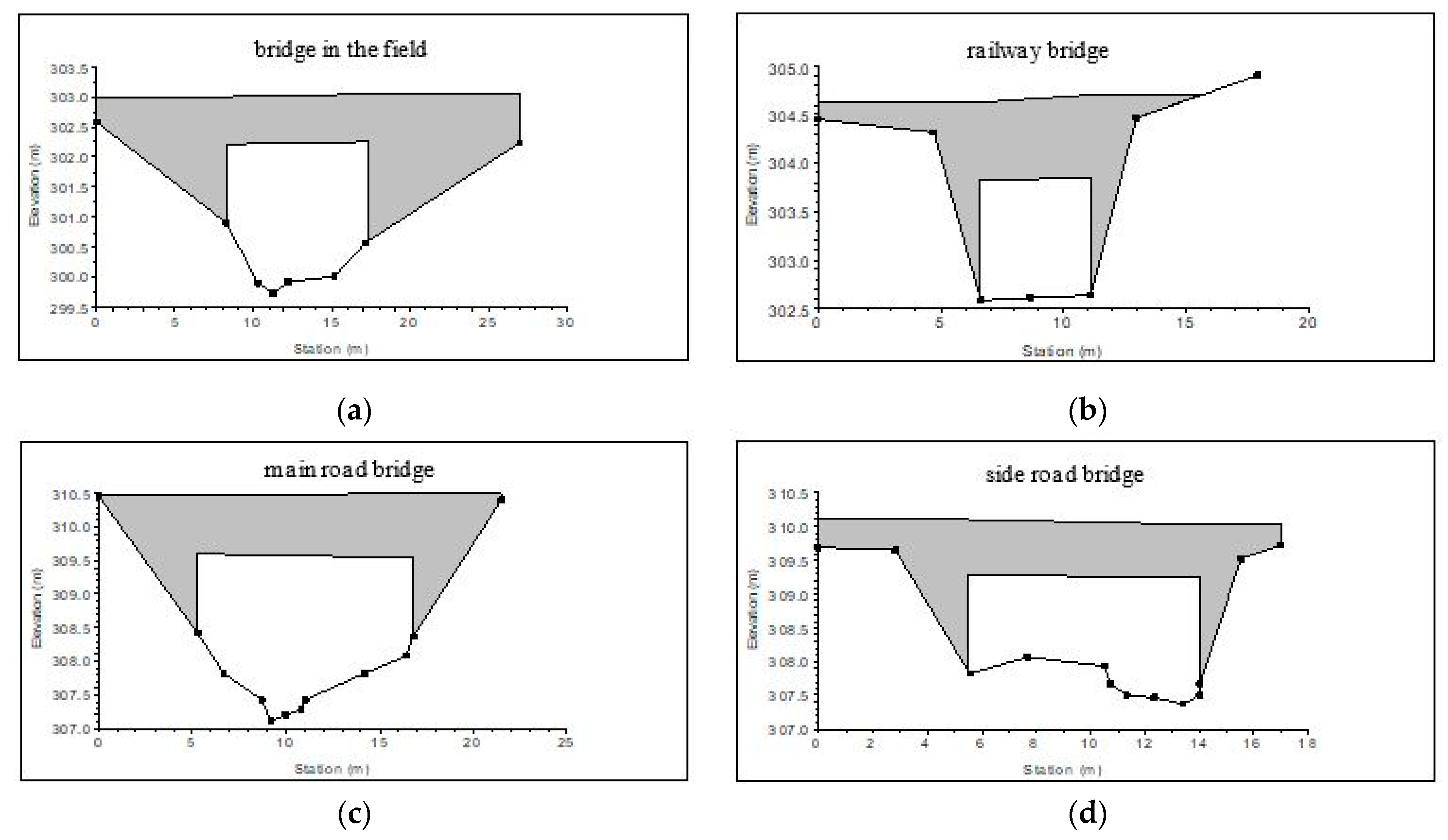
The modelled sections (
Figure 8) have a non-prismatic trapezoidal shape, but in some places also prismatic cross-sections with variable bottom width and different types of bank reinforcements (concrete panels, grass, blocks and stone). Through Veľká Lúka, the banks are lined with individual houses and outbuildings. At river km 0.748 (between PF 8 and PF 9) there is a bridge in the field, at river km 1.182 (between PF 16 and PF 17) there is a railway bridge, at river km 2.230 (between PF 23 and PF 24) there is a road bridge carrying the main road, at river km 2.279 (between PF 24 and PF 25) there is a side-road bridge (
Figure 9), at river km 2.575 there is a sill and at river km 2.596 a ford is located.
The final mathematical model describes the modelled sections with 38 cross-sections, with a mean distance of 91 m between them and a mean longitudinal slope of the stream bottom bed io = 5.14 ‰. The difference in height between bottom elevations at the beginning and end of the section is 314.04 m asl. −296.27 m asl. = 17.77 m. The total length of the mathematical model is 3455 m.
The roughness coefficients were calibrated according to the water level and discharge measured during the geodetic survey. The values of the Manning roughness coefficient for the main channel ranged from 0.025 to 0.15 and for the banks from 0.05 to 0.07 [
20].
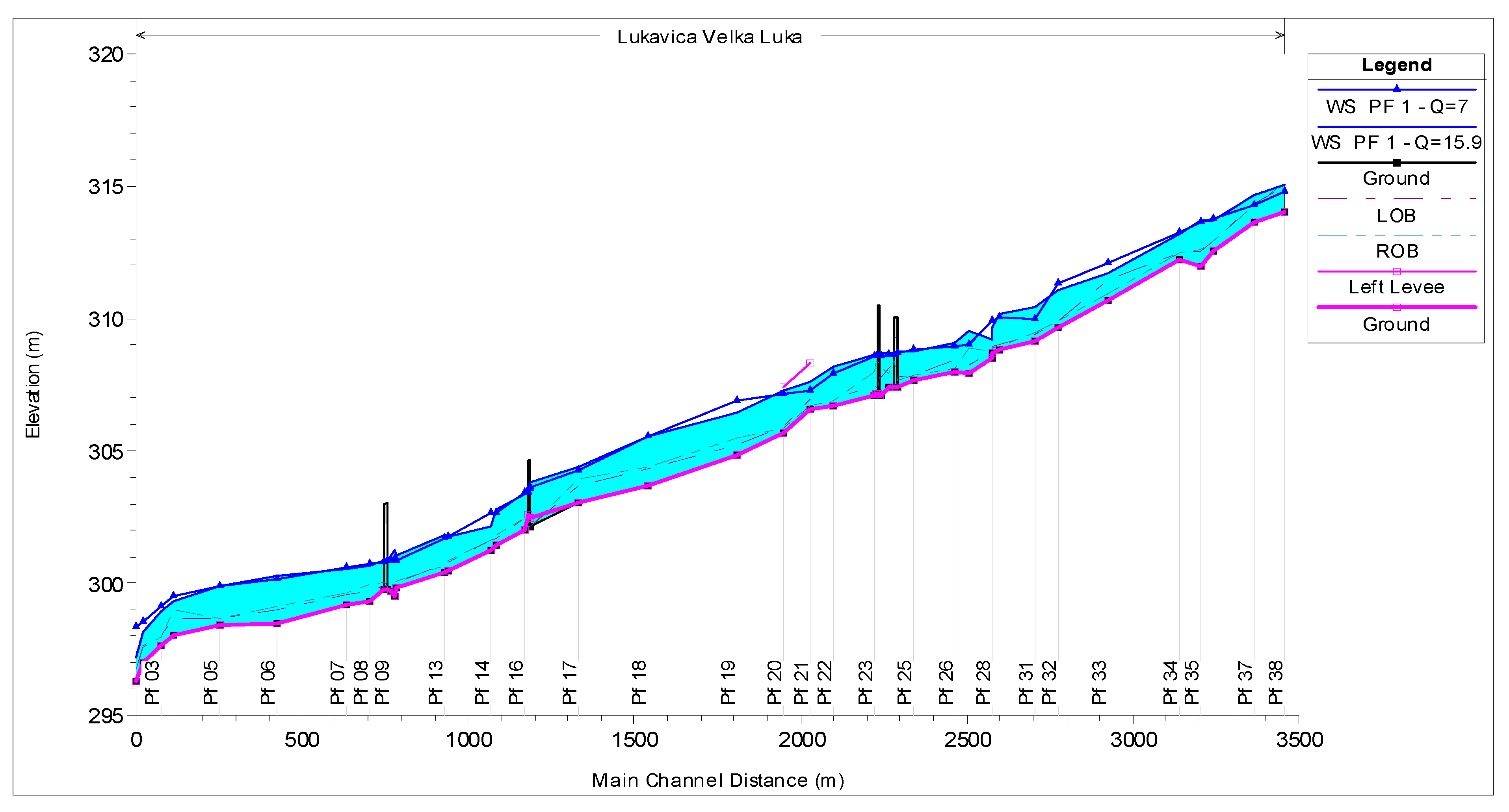
The calibrated model of the current state (
Figure 10) was used to determine the capacity of the Lukavica stream bed with sediments, which have meanwhile been removed by dredging in the central part of the village. The capacity of the stream bed with sediments reached the value Q
capacity = 7 m
3·s
−1, while the railway bridge below the village was able to carry through discharge
Q = 12 m
3·s
−1 in non-pressure mode.
The aim of this work, based on the research results, is to design an optimal alternative of flood protection, which would protect the inhabitants of Veľká Lúka and the surrounding environment from torrential rains. The following part presents the methodological procedure for assessing the effects of the proposed activities on the environment, as described in an earlier monograph [
18]. The sequence of individual stages, tasks and steps is based on the proposed methodological procedure, and this paper presents the results of its application.
2.5. Environmental Impact Assessment Based on Risk Analysis
The methodology for environmental impact assessment (EIA) of the proposed activity involves an assessment approach that is applicable to most environmental protection activity goals. Its main objective is to identify and assess the stressors that are significant in terms of their environmental impact. The method uses the Universal Matrix Risk Analysis method (UMRA). The basic principle of this methodology lies in calculation of the risk index [
18]. This can be quantified on the basis of the calculation of individual risks for each identified stressor impact on the environment. The stressor specification is based on the authors’ proposal and comments from the team of experts. For the assessment of a particular type of proposed activity, the stressors and their impacts need to be specified (reduced, supplemented) to include the essential features of the particular activity.
Figure 11 shows a schematic representation of the processing of each stressor in this methodology.
Probability is a measure of the possibility of an adverse effect due to the exposure of an environmental component to a stressor. To determine the probability Pi for the occurrence of an adverse effect due to the action of the stressor, four levels were selected for this study. To determine the probability value “Pi” (0.25–1), it was necessary to propose a probability indicator as well as assessment criteria for each level.
Consequences arise after a negative stressor acts on the environment and these consequences must also be examined at different levels. For example, damage to human health is usually considered at the individual level but environmental damage is usually assessed at the level of population, species or community. To determine the value of “Ci”, expressing a stressor’s degree of impact, four levels were again selected. To determine the value of “Ci” (0.25–1), it was necessary to propose an outcome indicator as well as assessment criteria for each level.
For the needs of the proposed procedure, it is important to determine the degree of risk that each stressor has for individual parts of the environment as a result of the activity considered [
18]. The individual risk value R
i is calculated using the following:
where
Pi represents the probability of adverse impact of the stressor on the environmental components and
Ci reflects the degree of impact of the stressor on the environment. Using this risk analysis matrix, it is possible to estimate the level of risk that can then be classified into four levels: negligible, low, medium and high. The four levels of probability and consequence are suggested based on the studied literature according to [
21]. Each of the four categories represents a certain degree of risk inherent in the proposed environmental activity resulting from its implementation. The order of suitability of the considered alternatives of the proposed activity is determined on the basis of the calculated risk R
i for each alternative. Determining the order depends on the degree of risk to the environment represented by each alternative.
The possibilities of applying the proposed EIA methodology to the proposed activity in practice are based on predetermined, defined and objectively justified indicators and criteria for determining the probabilities and consequences of the stressors/impacts. For the practical, methodological and pedagogical purposes of this research, a set of criteria (and their sub-criteria) were developed to support determination of the probability and consequence values
Pi and
Ci for
i = 1, 2, 3, ...., 10 for the identified environmental impacts of stressors connected with flood mitigation activities (see
Table 2).
Every impact of a stressor on an environmental component (•) is mathematically defined based on its degree of risk (the product of its probability and consequence). In order to determine the probability value Pi and the consequence value Ci, the tables below were developed to present the probability and consequence indicator values together with their criteria.
The following section presents the impacts of individual stressors on the above environmental components after determining the probability and consequence categories developed for the conditions of the Slovak Republic. It can be arranged for any other region and any other activity.
4. Environmental Impact Assessment
The Catalogue of Stressors [
18] is used to predict the impacts of the proposed activities on the environment. For the sake of formal completeness, the proposed Catalogue of 2nd-class Stressors, which contains a set of indicators and their criteria for determining the probability and impact of flood protection structures on the environment and public health, extended to include work specification, requires specification of the particular criteria for each of the indicators.
Based on the Catalogue of Stressors, the probability
Pi and the consequence
Ci were determined for each assessed alternative of the proposed activity in the area of Veľká Lúka. The values of the parameters in
Table 3 are empirically valid for the case study under consideration. This part of the study is the main result of the activity assessment according to the proposed methodological procedure using the proposed Catalogue of Stressors and is clearly summarized in
Table 3, according to the following colour classification of the assessed alternatives:
Alternative 0 Current state of the area
Alternative I Stream regulation
Alternative II Detention reservoir construction and stream regulation
Alternative III Detention reservoir construction 1
Alternative IV Detention reservoir construction 2
For the impact assessment, the individual risks of each stressor´s impact on the environmental components
Ri for each alternative considered were calculated according to Equation (1), as shown in
Table 4. For each individual risk, a score is calculated in
Table 4, according to the matrix of semi-quantitative risk analysis based on the colour distinction according to
Table 3.
The final steps in the methodological procedure are the decision-making stage after hydraulic modelling, the comparison of alternatives of the proposed activities based on their impact on the environment and the selection of the best alternative.
4.1. Determination of the Risk Index IRj for Each Alternative of the Proposed Activity
To determine the risk index
IRj, the individual risks
Ri of each stressor on the environmental component for each alternative considered were quantified (
Table 4).
The resulting risk indices were calculated (
Table 4) as a sum of the risk of each stressor. For Alternative 0,
IR0 = 5.25; for Alternative I,
IRI = 2.625; for Alternative II,
IRII = 2.25; for Alternative III,
IRIII = 2.125; and for Alternative IV,
IRIV = 2.375.
4.2. Environmental Risk Assessment of the Proposed Activity
Comparison of the alternatives of the proposed activity reveals that Alternative 0, “Current state of the area”, acquires according to
Table 4 a risk index value
IR0 = 5.25, and according to
Table 5 it represents the 2nd risk category of the proposed activity for the environment, so the risk level is medium;
Alternative I, “Stream regulation”, acquires a risk index
IRI = 2.625 according to
Table 4, and according to
Table 5 it represents the 3rd risk category of the proposed activity for the environment, so the risk level is low.
Alternative II, “Design of detention reservoir and stream regulation”, acquires a risk index
IRII = 2.25 according to
Table 4, and according to
Table 5 it represents the 4th risk category of the proposed activity for the environment, so the risk level is very low.
Alternative III, “Detention reservoir construction 1”, acquires according to
Table 4 a risk index
IRIII = 2.125, and according to
Table 5 it represents the 4th risk category of the proposed activity for the environment, so the risk is very low.
Alternative IV, “Detention reservoir construction 2”, acquires a risk index
IRIV = 2.375 according to
Table 4, and according to
Table 5 it represents the 4th risk category of the proposed activity for the environment, so the risk level is very low.
The assessment shows that all the options considered acquire different risk index values
IRj and fall into different risk categories. Based on the risk category, the actual degree of risk of the proposed activities for the environment can be assessed (see
Table 5).
The numerical values of the risk index
IRj of the assessed alternatives of the proposed activity in
Table 5 are classified in the 4th (“Detention reservoir construction”), 3rd (“Stream regulation”) and 2nd (“Current state of the area”) categories, and represent very low, low and medium levels of risk on the environment.
5. Conclusions
This research study is introducing a new approach to the environmental impact assessment of flood protection measures in flood-vulnerable areas. It presents a method that has not been applied before in practice. This method was developed by the authors and its applicability presents a possibility of its use in EIA practice for selecting the best alternative of proposed flood protection measures. Usually in EIA practice, the simple point method is used for selection of the best alternative of the activity. This method is more complex and more precise. The paper also presents the necessity of alternative solutions, especially in flood protection, that can be achieved by hydraulic modelling. Usually in EIA practice, two or three alternatives of the activity are compared. In our study, we have compared the zero alternative (no flood protection measure is realized) with four alternatives that were proposed for flood protection in the study area.
In the framework of the present study, the task was to propose possible flood protection measures on the Lukavica stream focusing on the village of Veľká Lúka, to hydraulically assess them and select the flood protection alternative that would be the best to prevent flooding from the stream bed at higher flow levels.
In the obtained data, no particular stream bed cross-section profiles were specified to be used for hydraulic analysis. For this purpose, 38 cross-sections were measured along the Lukavica stream from its confluence with the Hron (river km 0.000) up to the profile of the proposed detention reservoir dam (river km 3.455). Subsequently, the flood area of the planned detention reservoir was also examined in detail, and measured to obtain a digital terrain model and data on the volume and area of the future detention reservoir needed for the flood wave transformation.
Based on these data and measuring of the discharge in the Lukavica stream, mathematical models of the steady as well as unsteady states were prepared and calibrated. The HEC-RAS one-dimensional model was used to determine the Lukavica capacity discharge in the built-up area of Veľká Lúka. It was also used in unsteady conditions to calculate the designated flood wave transformation in two profiles. The capacity of the stream bed itself with sediments was limited to the value Qcapacity = 7 m3·s−1. The capacity of the modified Lukavica stream bed without sediments reached the value Qcapacity = 15.9 m3·s−1, which was considered as the limit value of the outflow from the planned detention reservoir upstream because of the terrain and built-up area.
Due to the fact that during the course of the project the sediments in the stream were removed by dredging in the central part of the village, a modified hydraulic model in the area of interest with removed sediments was used as well.
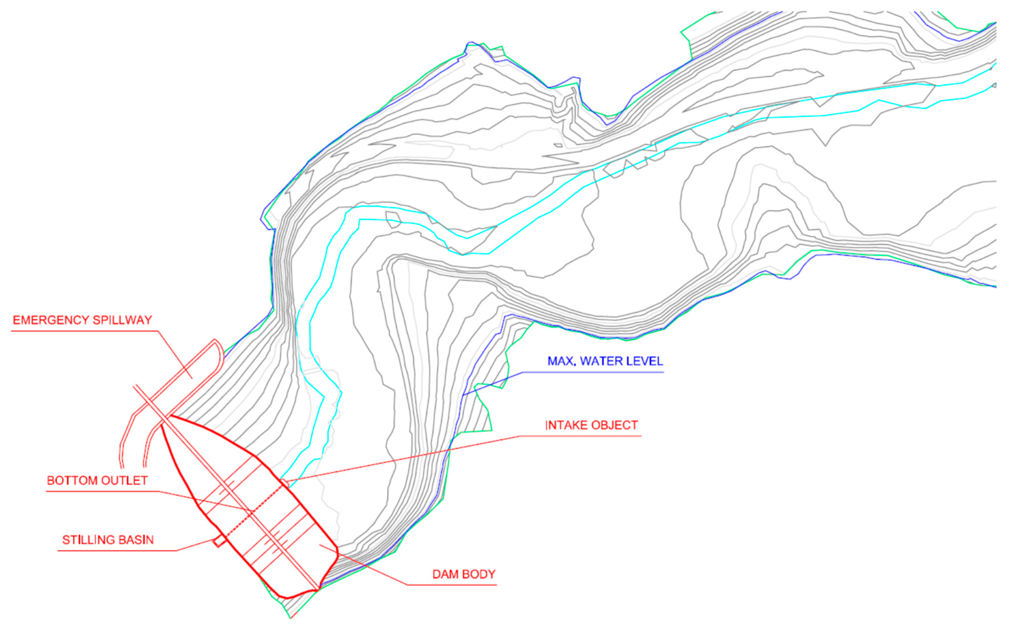
The cleaning of the stream bed will not help by itself to protect the village from flooding because the stream capacity does not even reach the value of Q5 = 21 m3·s−1, which is not sufficient. In order to reduce the flood discharge Q100 = 49 m3·s−1, it is necessary to implement a flood protection measures upstream the village, which will transform the flood wave in a suitable way. For this purpose, a detention reservoir is proposed at river km 3.455 on the Lukavica stream with a dam height of 11.5 m and a circular outlet culvert with a diameter of 1.5 m. The result of this design should be transformation of the designated flood wave into a culminating outflow with a value of 15.9 m3·s−1, which already meets the modified capacity of the stream bed in the area of interest (built-up area of the village).
The detention reservoir dam is designed as an earth-filled structure, the volume of which at the proposed elevation of the dam crest of 326 m asl. is calculated for the cross-section profile at approximately 25,650 m3. The bottom outlet is designed as circular with a diameter of 1.5 m, and hydraulically calculated as a culvert. The emergency spillway itself, which is also dimensioned for the value Q100 = 49 m3·s−1, is let into the right-bank part of the dam body at a sufficient level below the road.
There was also discussion of the possibility of building a detention reservoir for a lower designated flood wave further upstream using the profile at river km 7.1 on the Lukavica stream. As mentioned above, a necessary condition would be the implementation of flood protection measures on the Lukavica tributaries between the profiles at river km 3.366 and river km 7.1. In this case the flood wave Q100, according to the SHMI, a peak discharge of 39.5 m3·s−1 was used. The parameters of the flood wave enabled a detention reservoir to be designed with a dam height of 8.5 m and a bottom outlet with a diameter of 1.7 m. The culminating outflow in this case would reach a value of 17.3 m3·s−1.
It does not make sense to carry out stream bed regulation in several stages and evaluate them separately for individual sections. It would be appropriate to implement uniform stream bed regulation in the entire area of interest for capacity discharge. Another problematic place in the village is certainly the profile of the “ford”, in which the water depth at capacity discharge Qcapacity = 15.9 m3·s−1 will be 1.35 m and 1.58 m at Q5 = 21 m3·s−1.
The proposal of the optimal alternative is based on a comparison of the degree of risk of the proposed activity for the environment, on the basis of which the order of suitability of the assessed alternatives can be stated as follows: (1) Alternative III, “Detention reservoir construction 1”; (2) Alternative II; (3) Alternative IV; (4) Alternative I; and (5) Alternative 0.
First place belongs to the alternative that is optimal in terms of the degree of risk it poses to the environment. The second to fourth places are taken by the alternatives that are less acceptable, and fifth place belongs to the alternative that is least acceptable and most risky in terms of the degree of risk for the environment.
Based on this assessment, the proposal of the optimal alternative can be justified as follows: The comparison of alternatives of the proposed activity, i.e., flood protection facilities on the Lukavica stream at the village of Veľká Lúka, shows that all six assessed alternatives represent different levels of risk for environment. It is on the basis of this risk index IRj that Option III can be assessed overall as optimal in terms of the expected environmental impacts and therefore the construction of a detention reservoir in the valley of the Lukavica stream above the village of Veľká Lúka is recommended. This flood protection structure is included in the 4th category of water management facilities, as designed on the basis of a calculated risk index and presenting an overall very low level of risk to the environment.


 ,
, 


