
Analysis of Pore Water Pressure and Piping of Hydraulic Well

Abstract
1. Introduction
2. Seepage Behavior and Hydraulic Well
2.1. Seepage Behavior
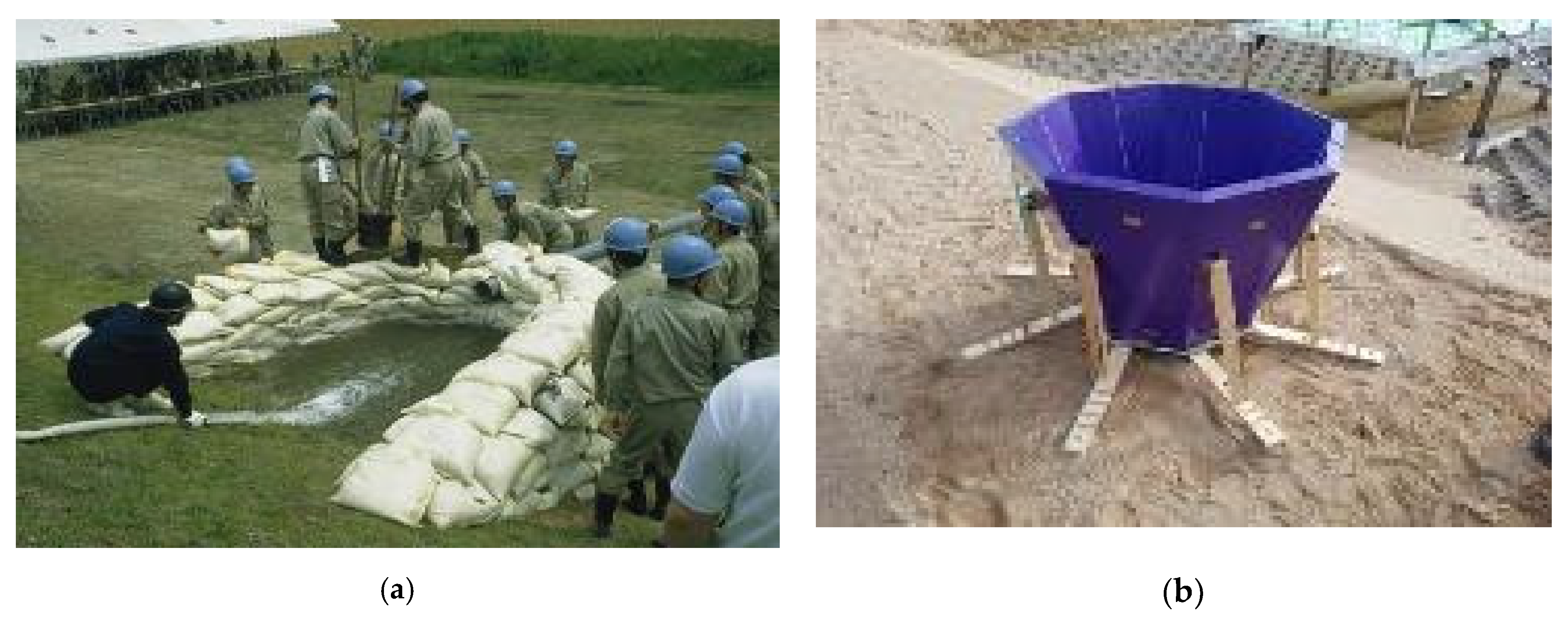
2.2. Hydraulic Well
3. Embankment Test and Pore Water Pressure of Hydraulic Well
3.1. Experimental Method
3.1.1. Embankment Soil
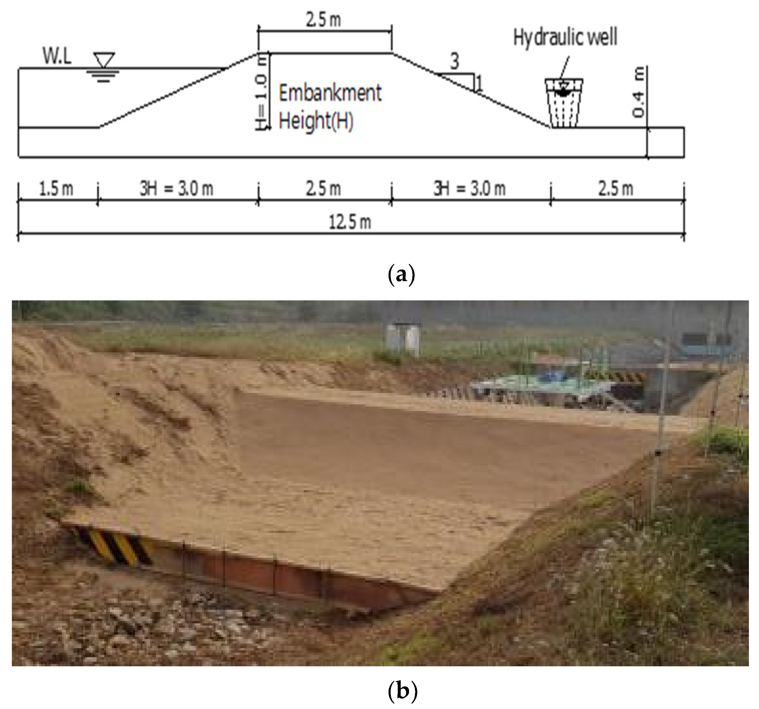
3.1.2. Construction of the Experimental Embankment
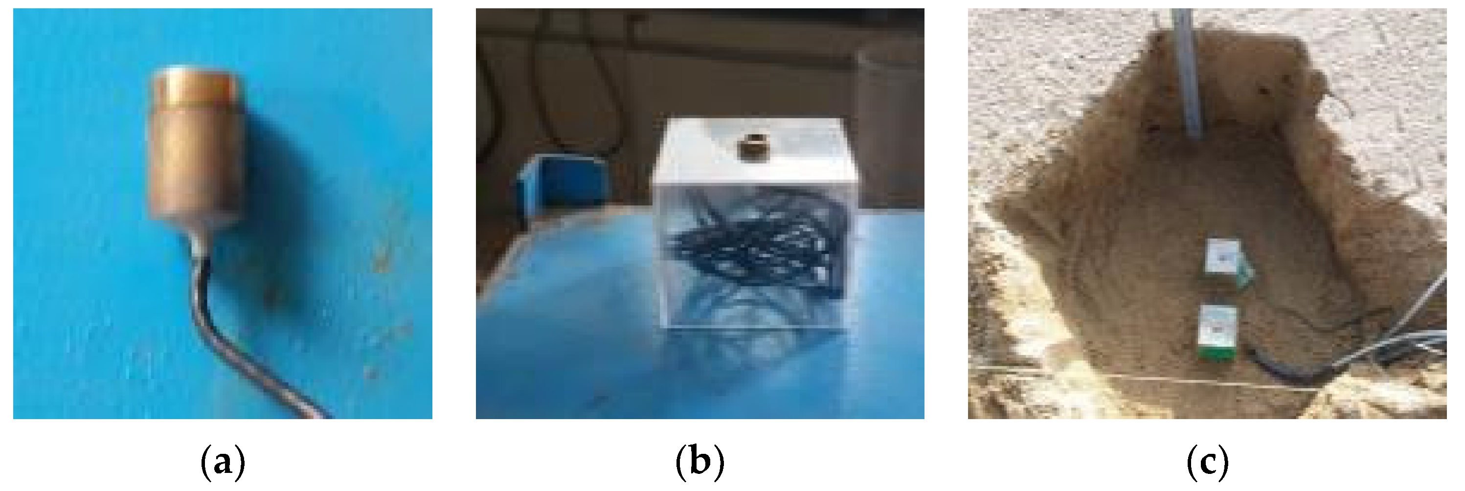
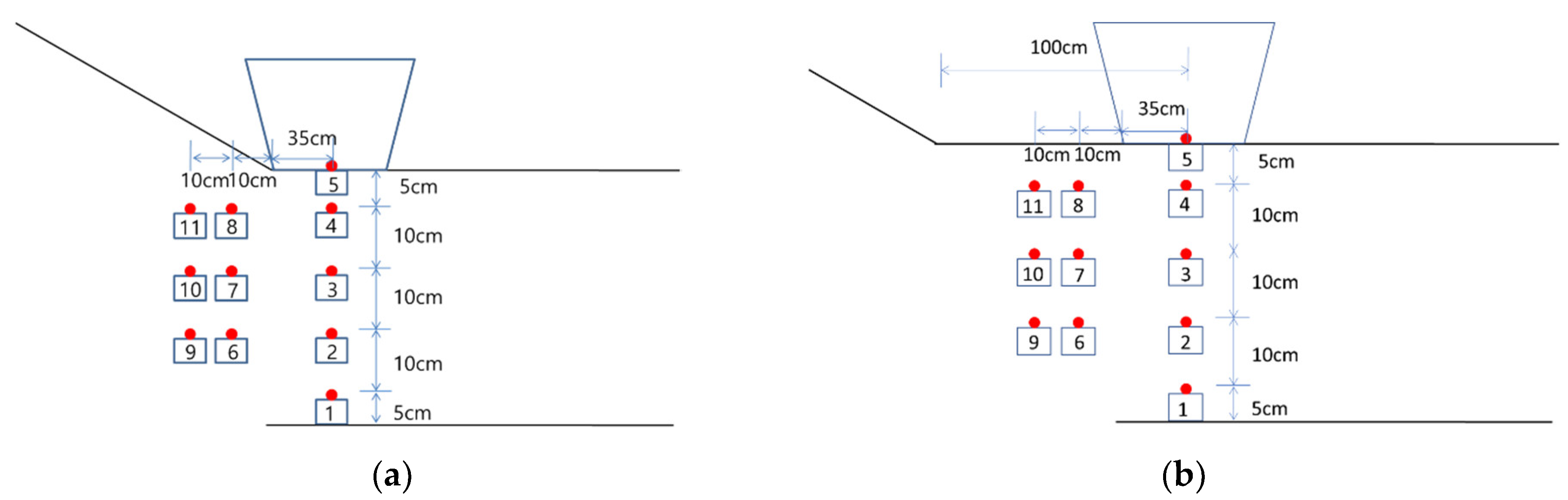
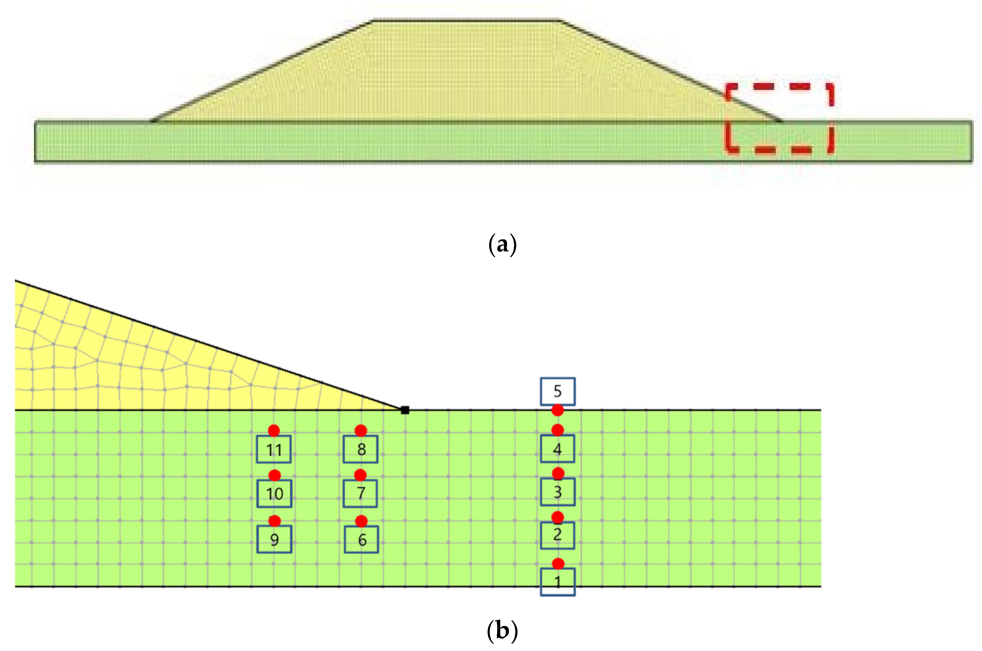
3.1.3. Pore Water Pressure Sensor Arrangement: Case 1 and Case 2
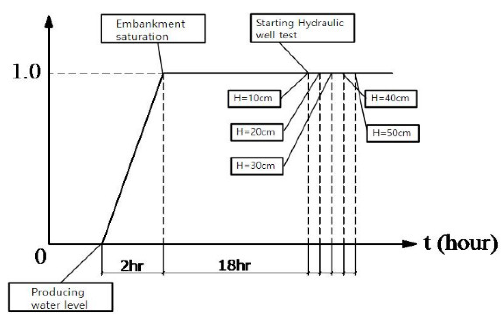
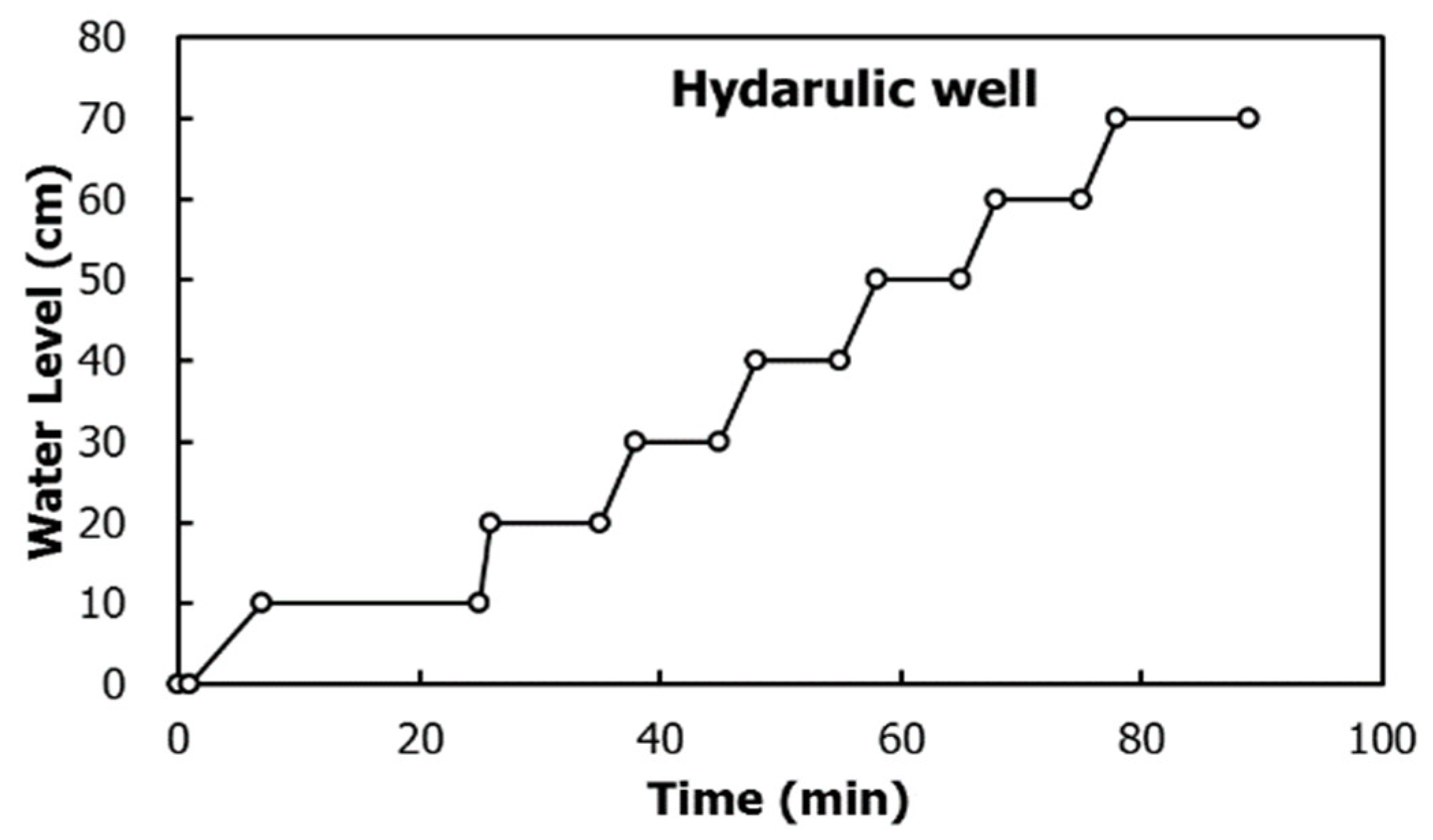
3.1.4. Water Level of Hydraulic Well
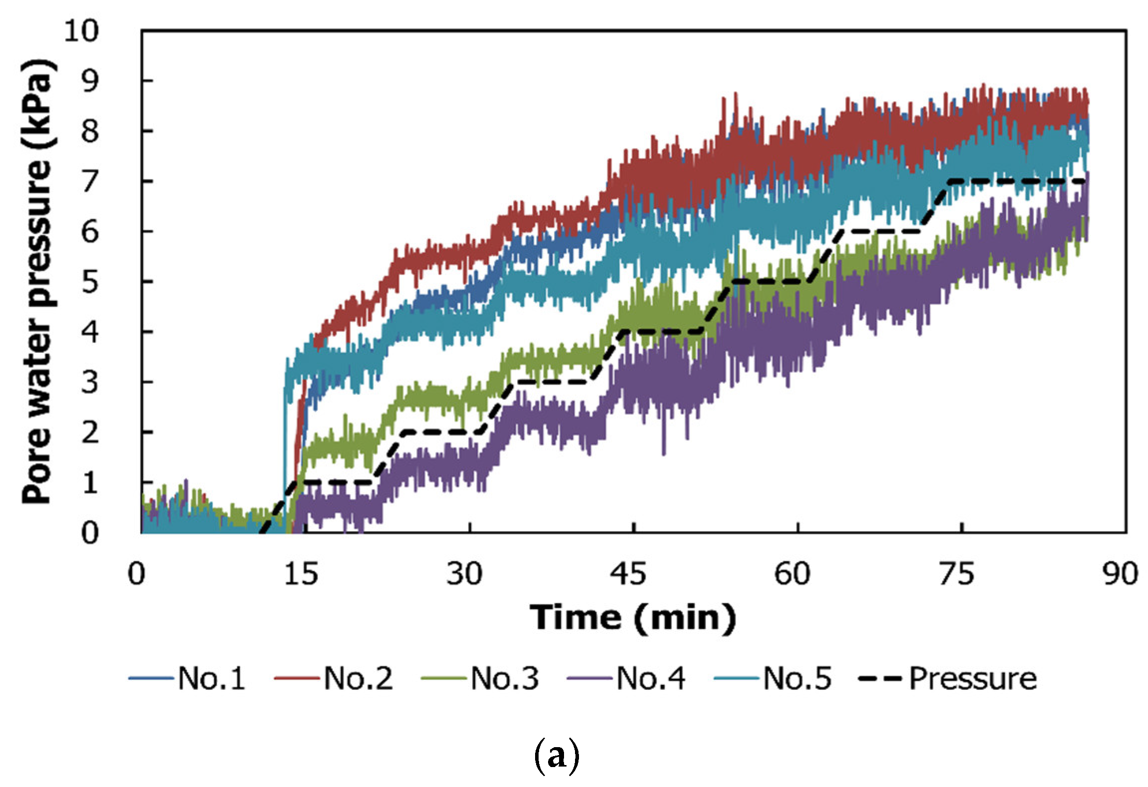
3.2. Experiment Results
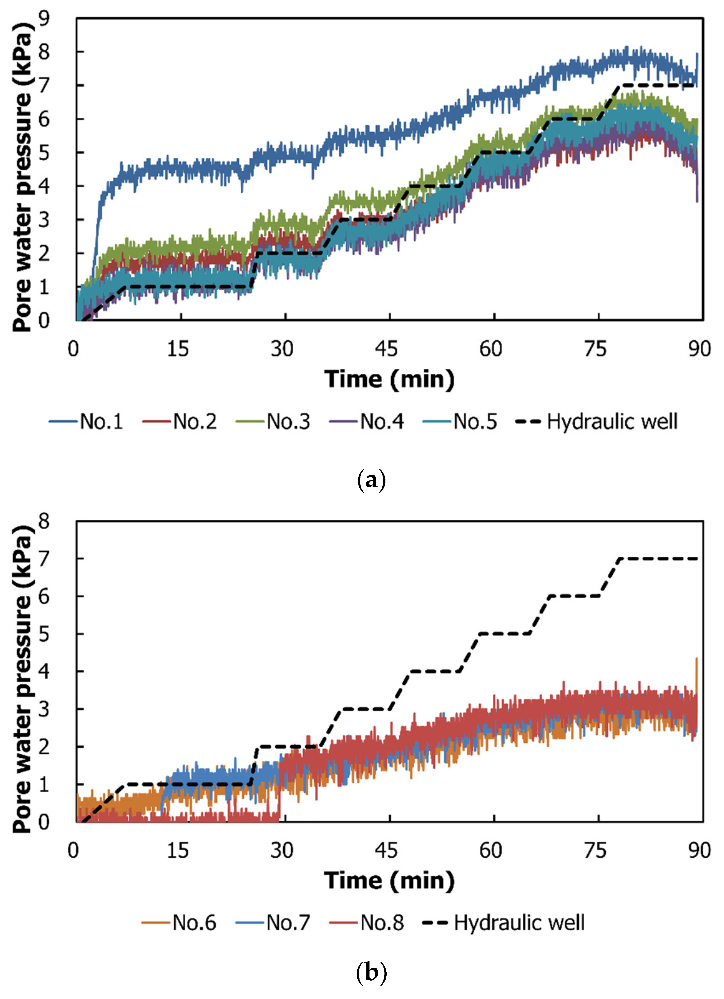
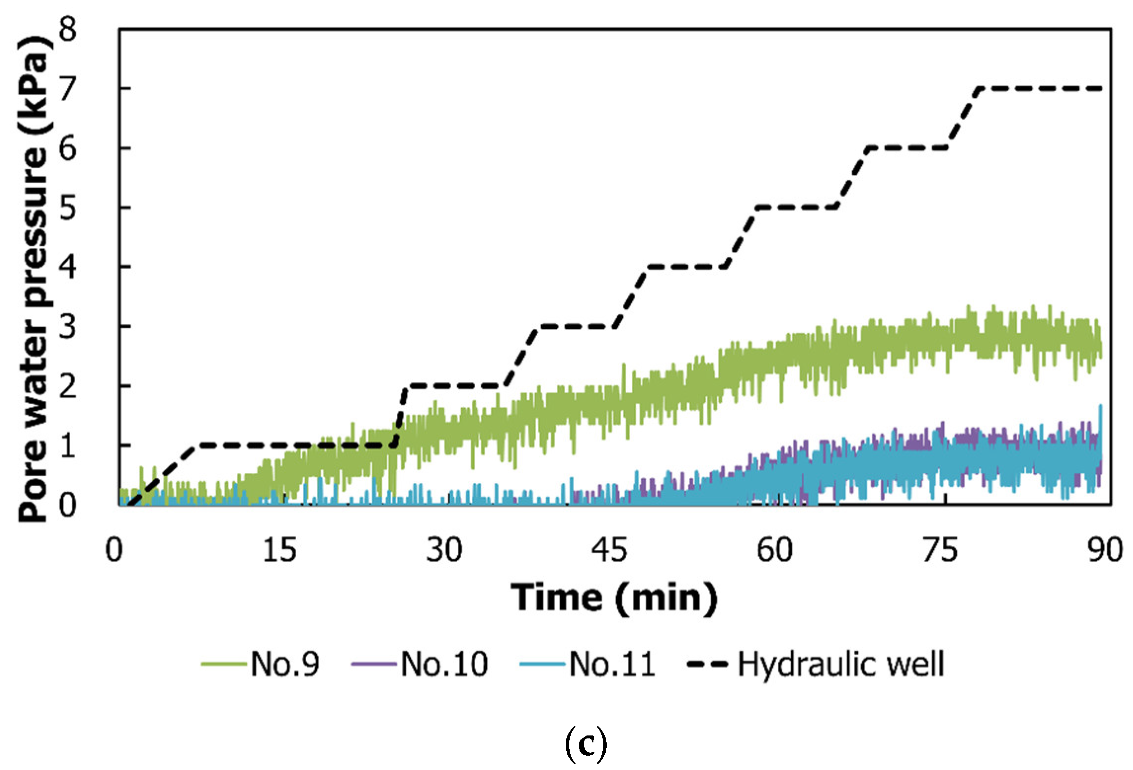
3.2.1. Case 1
3.2.2. Case 2
4. Numerical Analysis
4.1. Analysis Condition
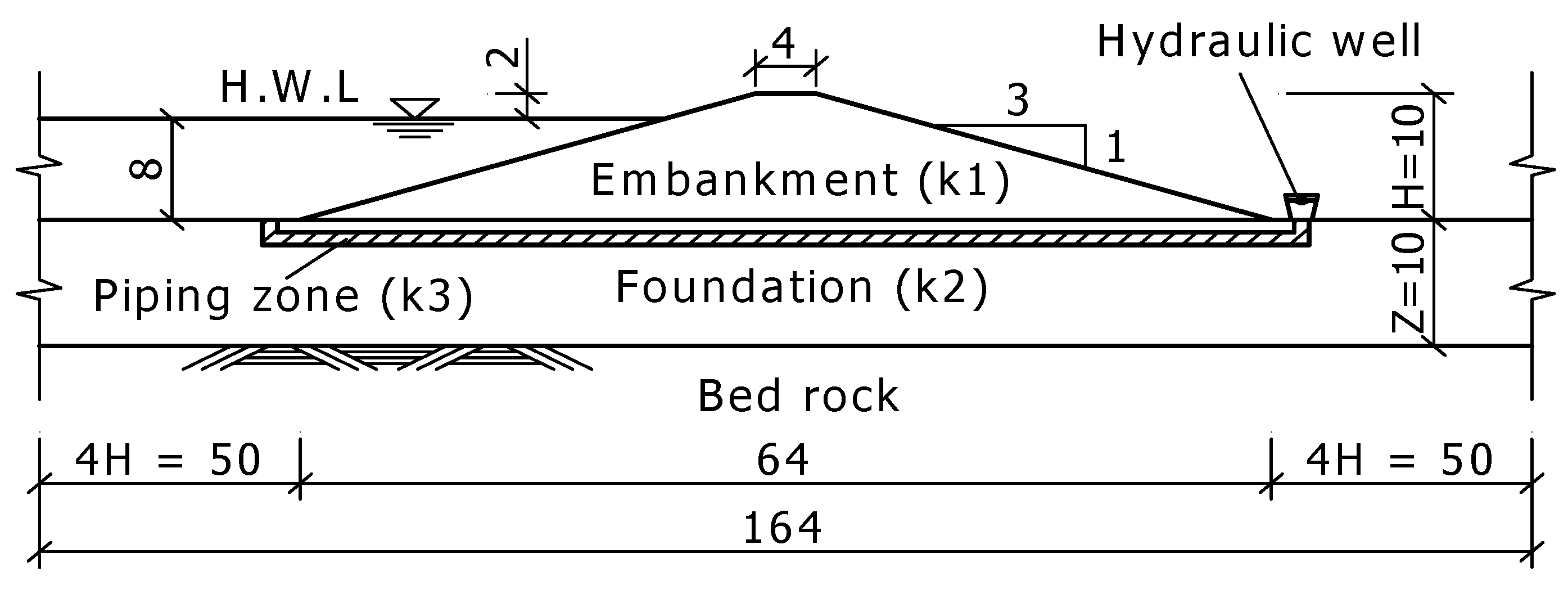
4.1.1. Embankment Section and Mesh Size
4.1.2. Soil Water Characteristic Curve and Water Level Conditions
4.2. Analysis Results
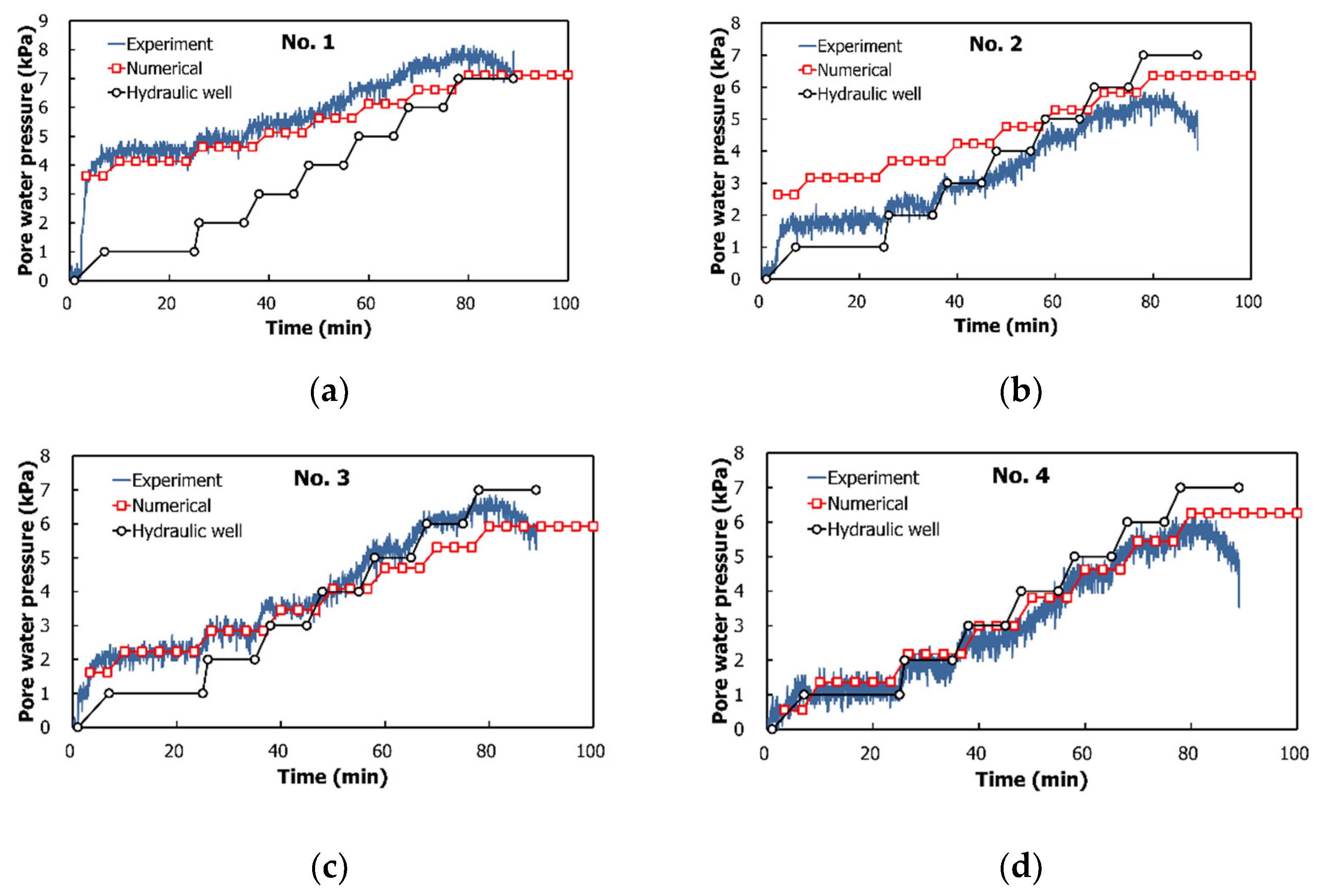
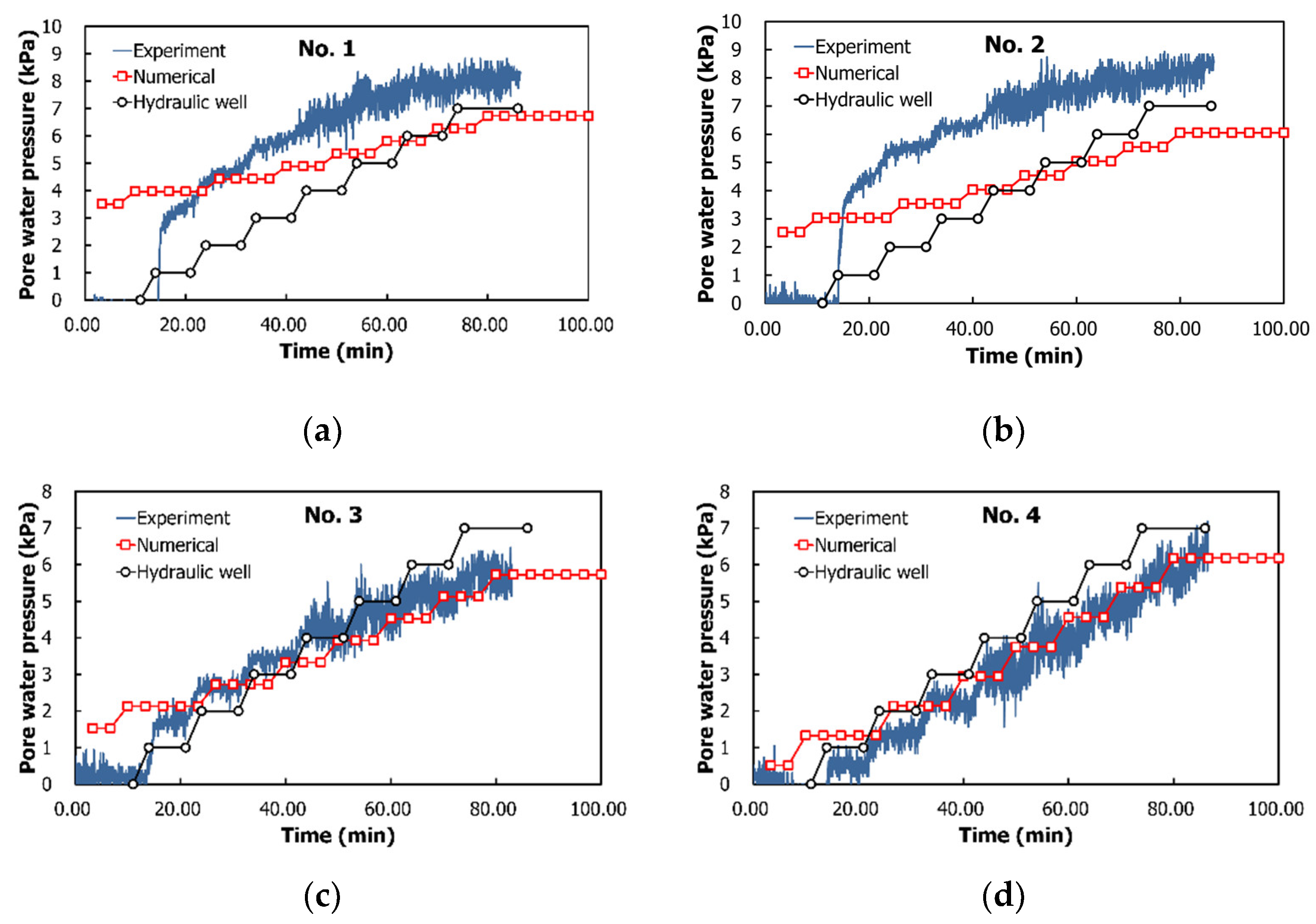
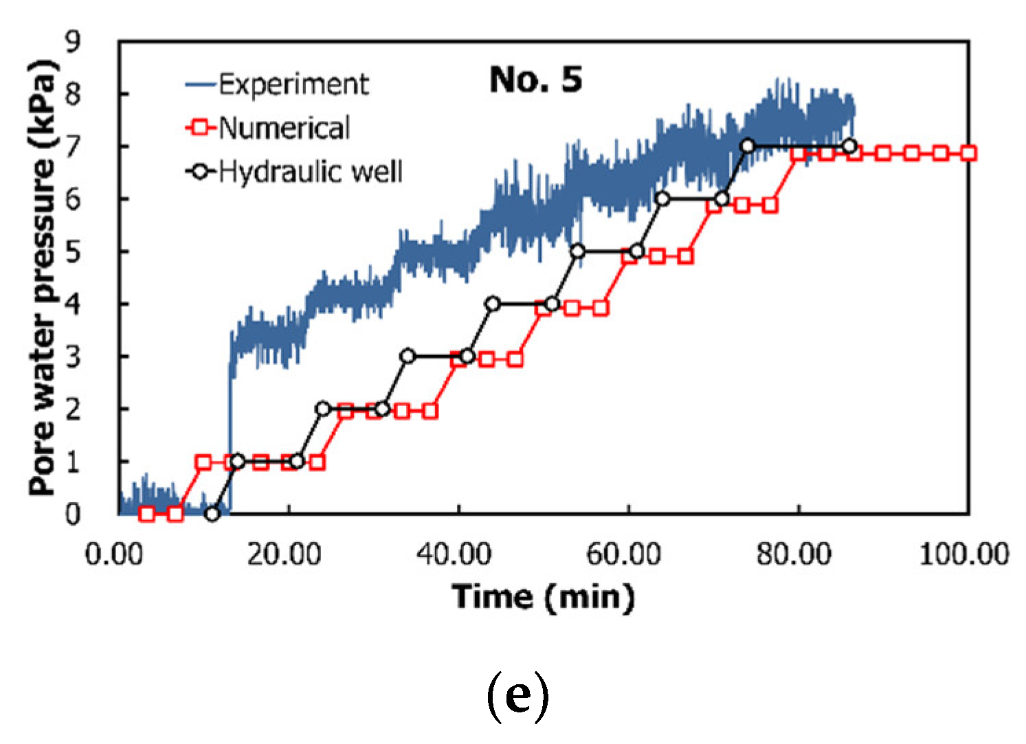
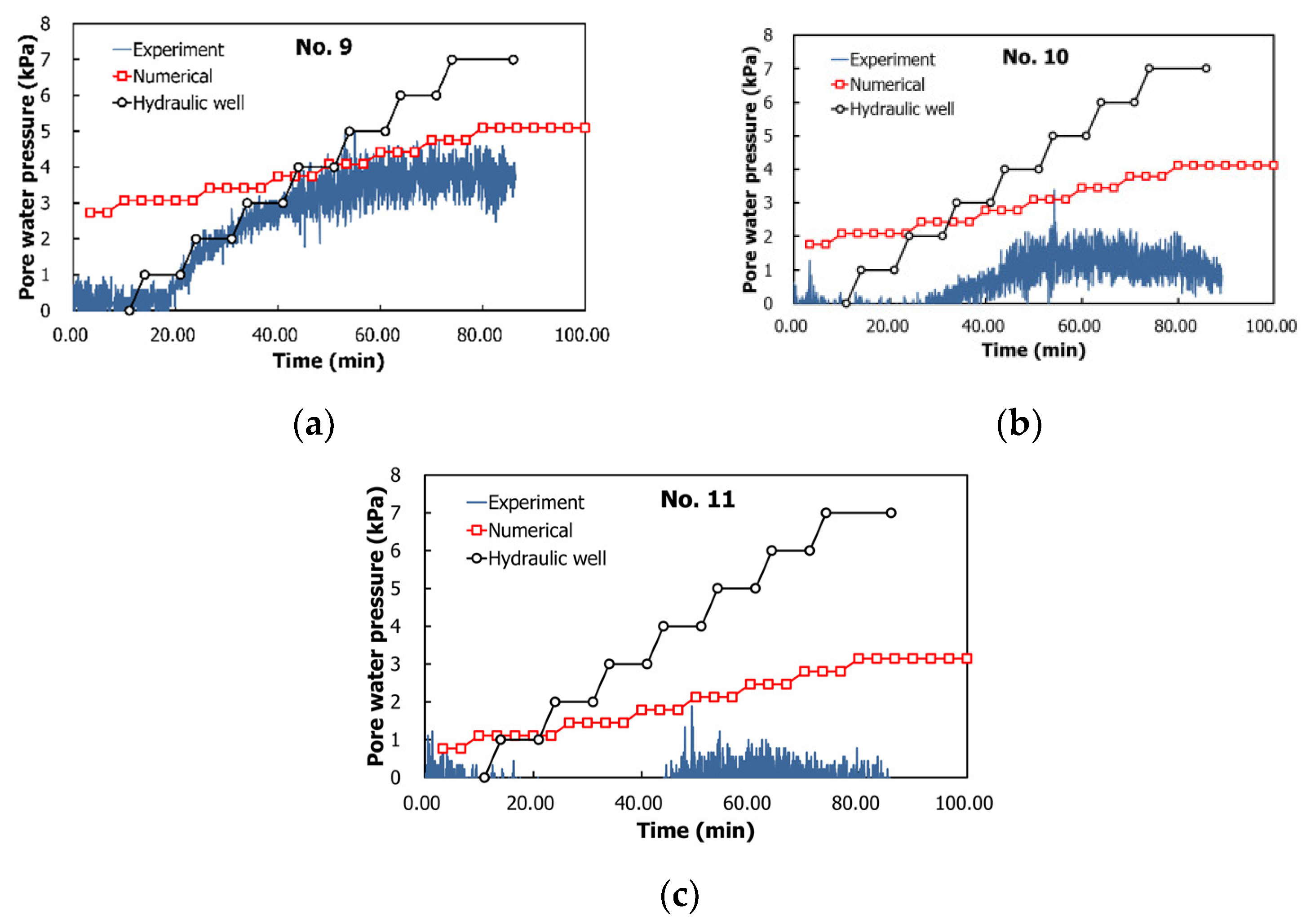
4.2.1. Experiment and Numerical Analysis Results of Case 1
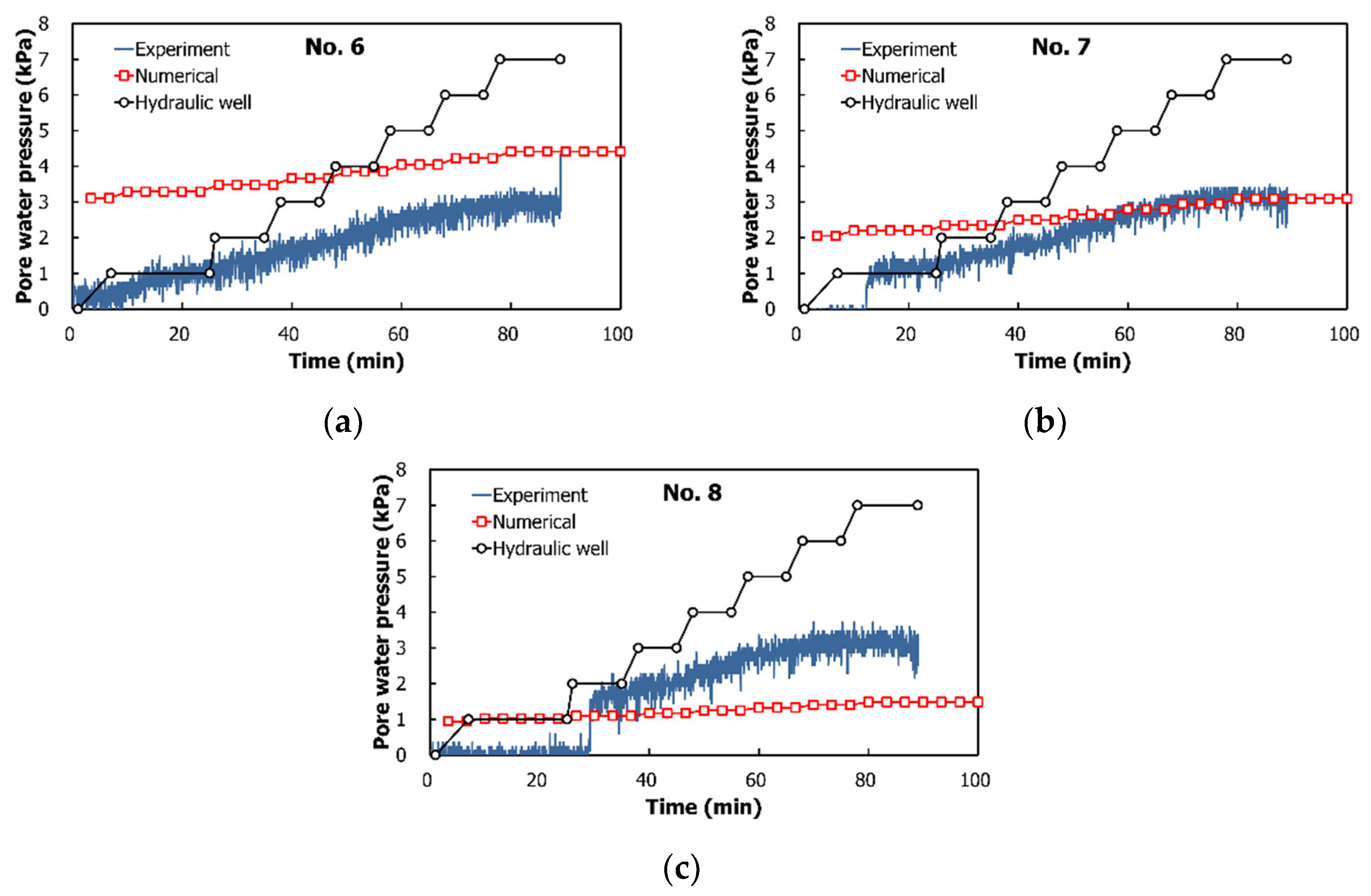
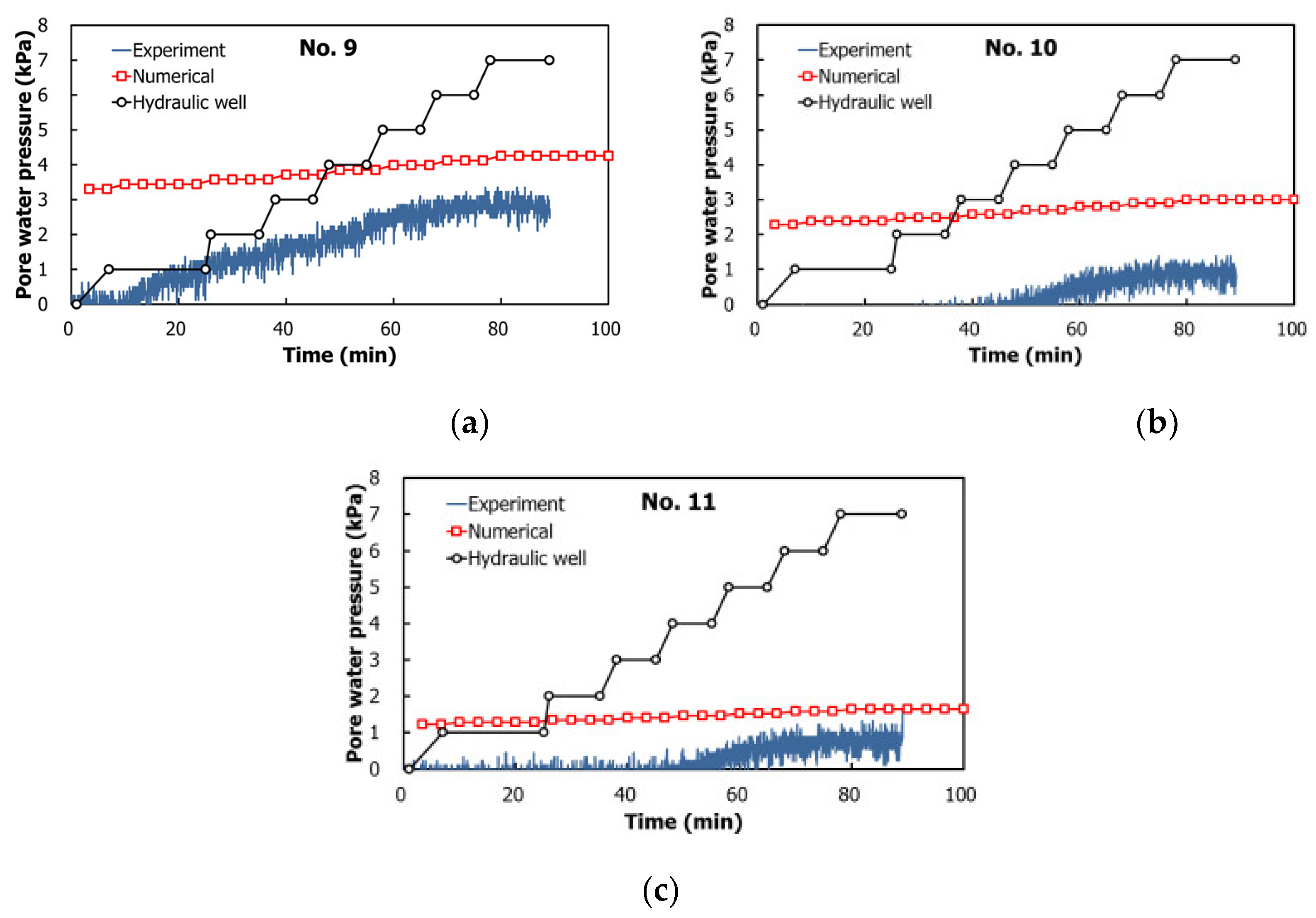
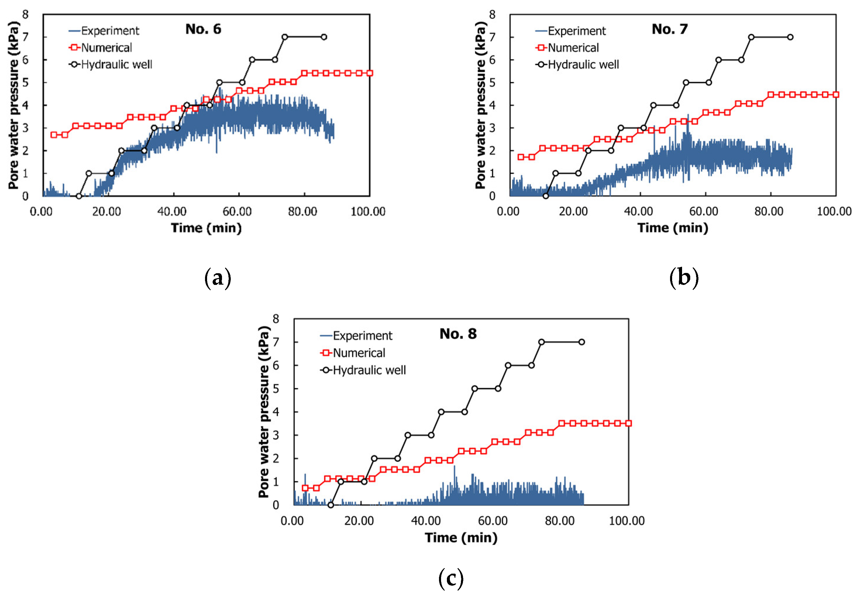
4.2.2. Experiment and Numerical Analysis Results of Case 2
5. Piping
5.1. Analysis Conditions
5.1.1. Embankment Section and Mesh Size
5.1.2. Soil Water Characteristic Curve and Water Level Conditions
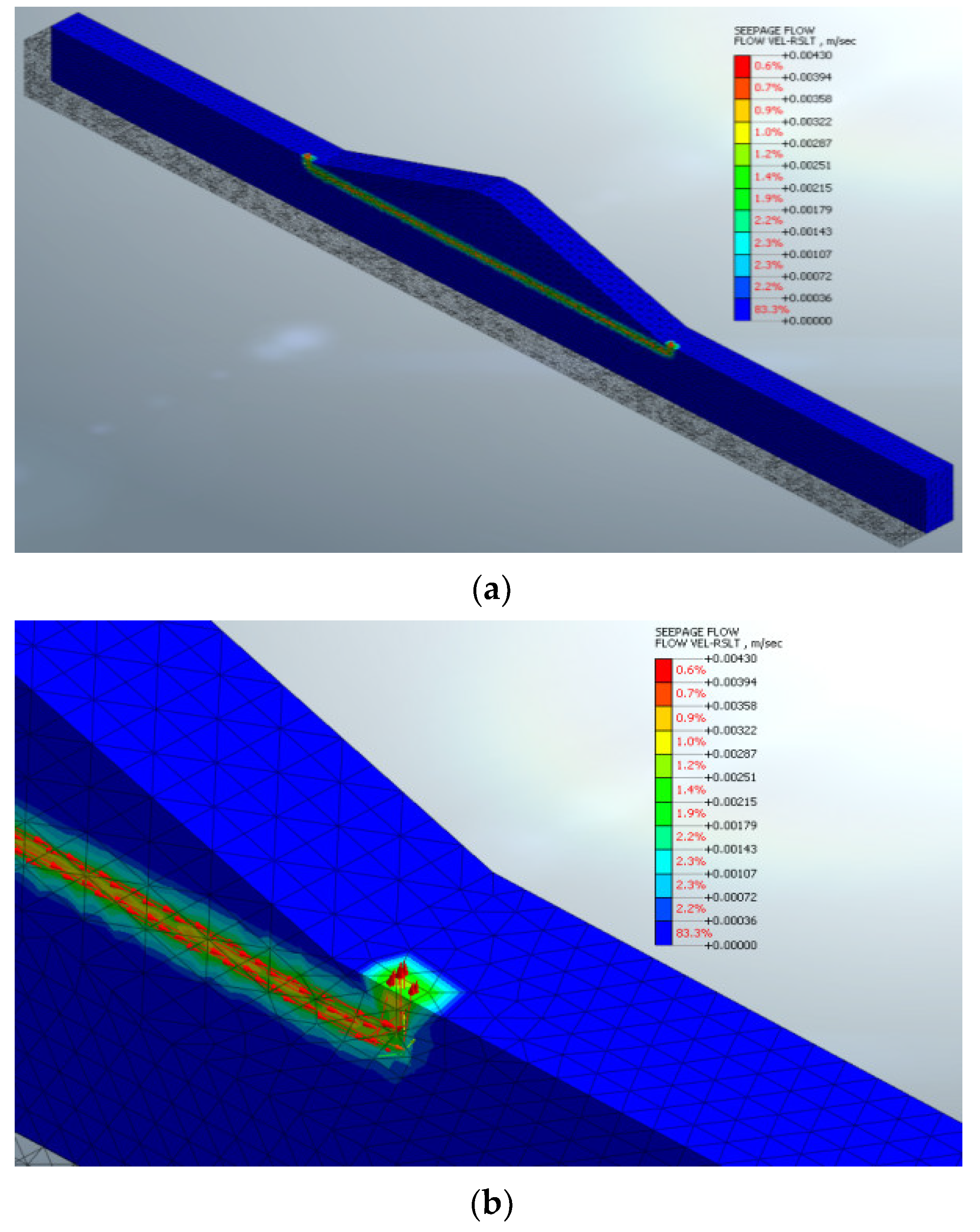
5.2. Analysis Results
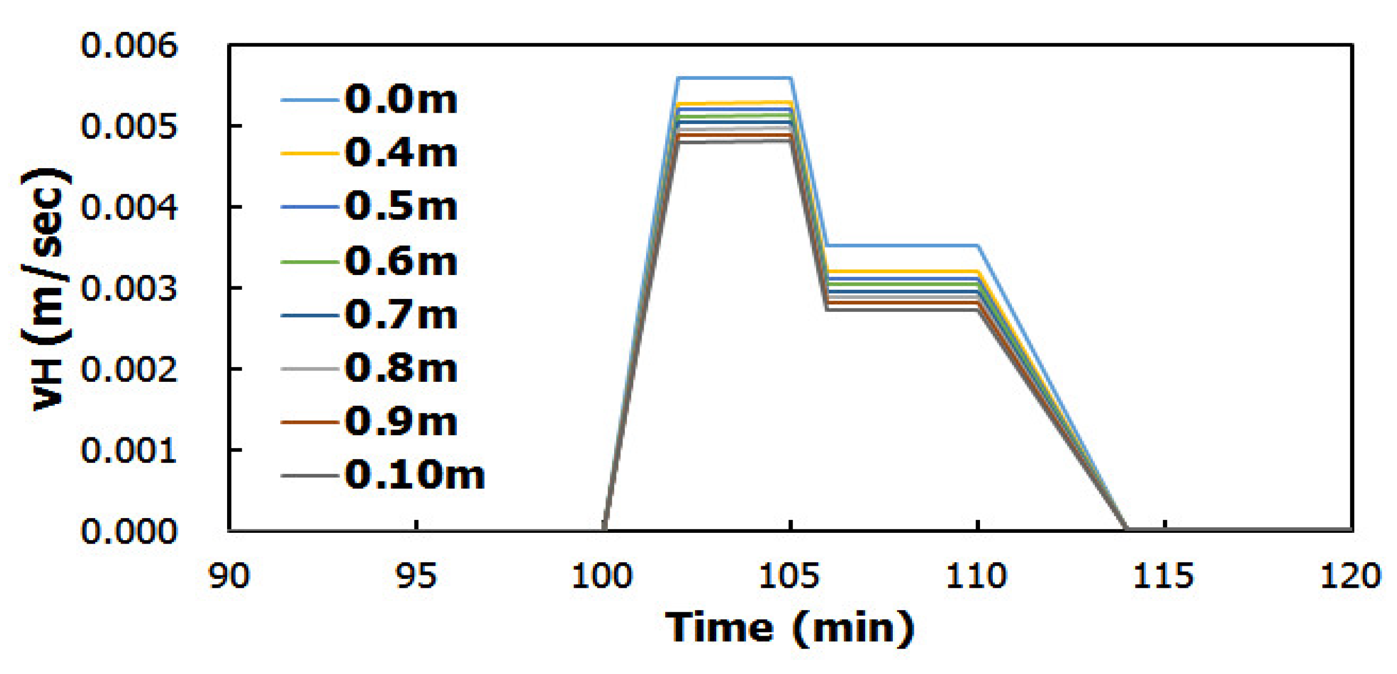
5.2.1. Analysis by Water Level of Hydraulic Well
5.2.2. Analysis by Location of Hydraulic Well
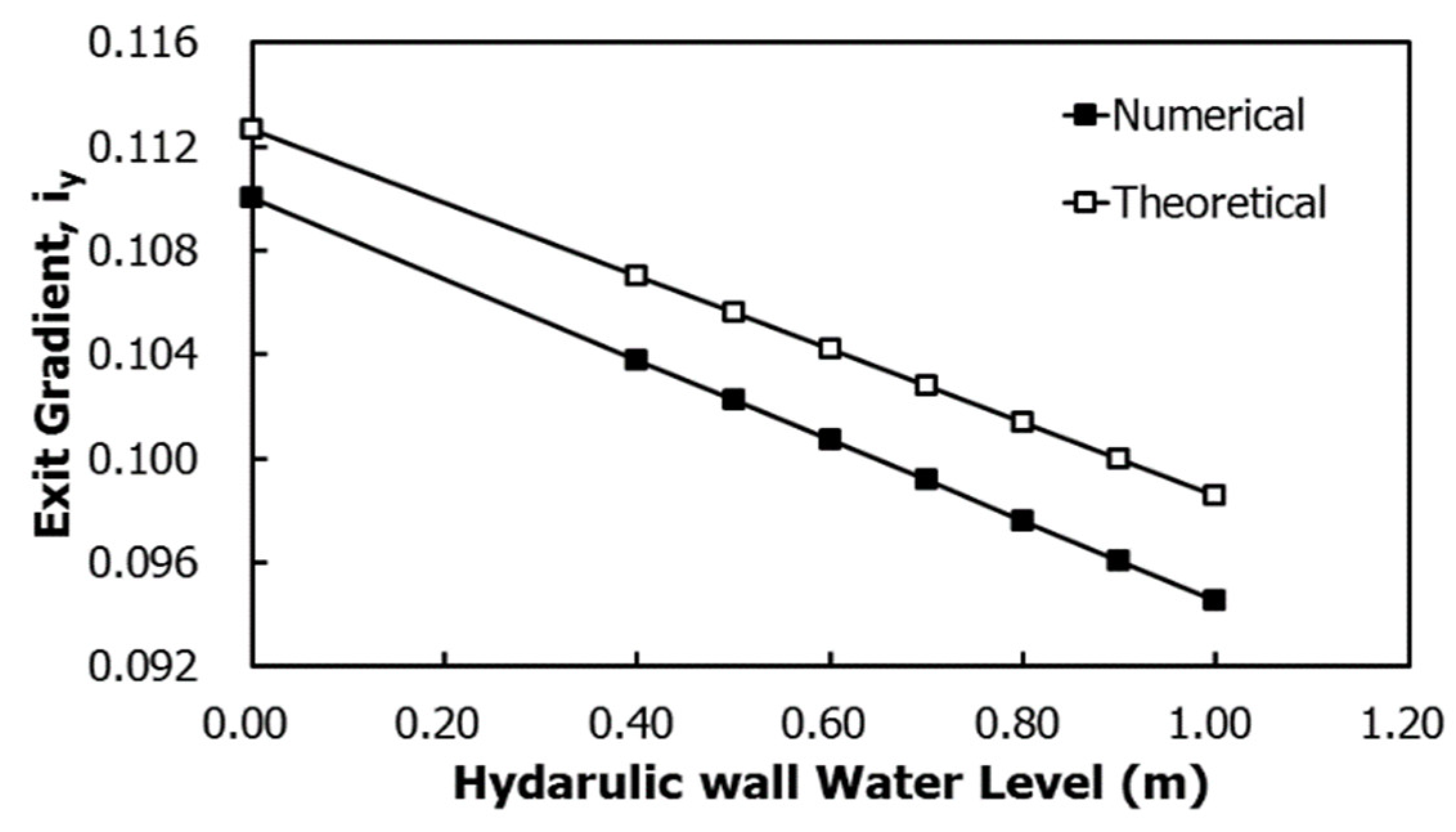
5.2.3. Hydraulic Gradients of Theory and Numerical Analysis
6. Conclusions
6.1. Comparison with Permanent Method
6.2. Pore Water Pressure
6.3. Piping
6.4. Hydraulic Well
Author Contributions
Funding
Conflicts of Interest
References
- Kim, K.; Jo, K. A Study on the Estimation of Leakage and the probing Leakage in the River Bank. Korean J. Korean Soc. Soil Ground Water Environ. 1999, 6, 213–217. [Google Scholar]
- KICT. The Final Report of the River Embankment Related Advanced Technology Development; Korea Institute of Civil Engineering and Building Technology: Gyeonggi-do, Korea, 2004; pp. 23–31, 68–78. [Google Scholar]
- KGS. Dam and Embankment Design and Construction Safety Management Technology; Goomi Book: Korea, 2012. [Google Scholar]
- Im, D.-K.; Yeo, H.-K.; Kim, K.-H.; Kang, J.-G. Suitability Analysis of Numerical Models Related to Seepage through a Levee. J. Korea Water Resour. Assoc. 2006, 39, 241–252. [Google Scholar]
- Kim, J.; Moon, I. Analysis of River Levee Failure Mechanism by Piping and Remediation Method Evaluation. J. Korea Acad. Ind. Coop. Soc. 2017, 18, 600–608. [Google Scholar]
- Jung, H.; Byun, Y.; Chun, B.; Choi, B.; Kim, J. Numerical Analysis for Integrity Evaluation of River Bank. J. Korean Geoenviron. Soc. 2010, 11, 19–26. [Google Scholar]
- Taylor, R.L.; Brown, C. Darcy flow solutions with a free surface. J. Hydraul. Div. 1967, 93, 25–33. [Google Scholar] [CrossRef]
- Neuman, S.P.; Witherspoon, P.A. Finite element method of analyzing steady seepage with a free surface. Water Resour. Res. 1970, 6, 889–897. [Google Scholar] [CrossRef]
- Uno, T.; Morisugi, H.; Sugil, T.; Nakano, Y. Stability evaluation of river levees on the basis of actual levee breachings. Doboku Gakkai Ronbunshu 1988, 1988, 161–170. [Google Scholar] [CrossRef]
- Office, M.R.N.H. Flood Prevention Handbook; Shikoku Regional Development Bureau: Shikoku, Japan, 2011.
- Association, K.W.R. River Design Standard; Ministry of Land, Transport and Maritime Affairs: Korea, 2009.
- Van Genuchten, M.T. A closed-form equation for predicting the hydraulic conductivity of unsaturated soils. Soil Sci. Soc. Am. J. 1980, 44, 892–898. [Google Scholar] [CrossRef]
- Carsel, R.F.; Parrish, R.S. Developing joint probability distributions of soil water retention characteristics. Water Resour. Res. 1988, 24, 755–769. [Google Scholar] [CrossRef]
- Kwon, K. An Improved Design Method of Levee Culvert Using 3D Seepage Analysis. Ph.D. Thesis, Kyunghee University, Seoul, Korea, 2007. [Google Scholar]
- FEMA. Evaluation and Monitoring of Seepage and Internal Erosion; Interagency Committee on Dam Safety (ICODS): Washington, DC, USA, 2015. [Google Scholar]


| Classification | Silty Sand | |
|---|---|---|
| Characteristics | ||
| 2.674 | ||
| Plasticity Index | Non-Plasticity | |
| Particle Size | #200 (%) | 2.4 |
| Coefficient of Curvature () | 0.9 | |
| Coefficient of Uniformity () | 3.6 | |
| Unified Soil Classification System (USCS) | SP | |
| Compaction | (kN/) | 17.24 |
| Optimum Moisture Content ( (%)) | 13.9 | |
| Shear Strength | Cohesion (kPa) | 16.0 |
| Inner Friction Angle (Φ (°)) | 38.2 | |
| Textural Class | Sand |
|---|---|
| Unified Soil Classification System (USCS) | SP |
| Saturated Volumetric Water Content, ) | 0.045 |
| Residual Volumetric Water Content, ) | 0.43 |
| Reciprocal of the Air Entry Value, | 14.5 |
| Coefficient Related to the Slope of the Soil Water Characteristic Curve, | 2.68 |
| Slope-Related Coefficient at High Levels of Capillary Absorption, | 0.627 |
| Permeability Coefficient, ) | 0.0009 |
| Time | Seepage Velocity (m/s) by the Water Level ( ) of the Hydraulic Well | ||||||||
|---|---|---|---|---|---|---|---|---|---|
| h | s | 0 m | 0.4 m | 0.5 m | 0.6 m | 0.7 m | 0.8 m | 0.9 m | 1.0 m |
| 100 | 360,000 | 0.00000 | 0.00000 | 0.00000 | 0.00000 | 0.00000 | 0.00000 | 0.00000 | 0.00000 |
| 101 | 363,600 | 0.00281 | 0.00265 | 0.00261 | 0.00257 | 0.00253 | 0.00249 | 0.00245 | 0.00241 |
| 102 | 367,200 | 0.00560 | 0.00528 | 0.00521 | 0.00513 | 0.00505 | 0.00497 | 0.00489 | 0.00481 |
| 105 | 378,000 | 0.00561 | 0.00529 | 0.00521 | 0.00513 | 0.00505 | 0.00497 | 0.00490 | 0.00482 |
| 106 | 381,600 | 0.00352 | 0.00320 | 0.00312 | 0.00304 | 0.00297 | 0.00289 | 0.00281 | 0.00273 |
| 110 | 396,000 | 0.00352 | 0.00320 | 0.00312 | 0.00305 | 0.00297 | 0.00289 | 0.00281 | 0.00273 |
| 114 | 410,400 | 0.00002 | 0.00002 | 0.00002 | 0.00002 | 0.00002 | 0.00002 | 0.00002 | 0.00002 |
| 120 | 432,000 | 0.00001 | 0.00002 | 0.00002 | 0.00002 | 0.00002 | 0.00002 | 0.00002 | 0.00002 |
| 0.00561 | 0.00529 | 0.00521 | 0.00513 | 0.00505 | 0.00497 | 0.00490 | 0.00482 | ||
| 100.0 | 94.4 | 93.00 | 91.6 | 90.2 | 88.7 | 87.3 | 85.9 | ||
| Unapplied | Horizontal Distance from the Piping Point (m) | |||||||
|---|---|---|---|---|---|---|---|---|
| None | −3 | −2 | −1 | 0 | 1 | 2 | 3 | |
| v (m/s) | 0.0024 | 0.0024 | 0.0024 | 0.0128 | 0.0022 | 0.0129 | 0.0024 | 0.0024 |
| 100.0 | 100.0 | 100.0 | 526.8 | 90.1 | 530.9 | 100.0 | 100.0 | |
| 0.0 | 71.0 | 8.00 | 0.1127 |
| 0.4 | 7.60 | 0.1070 | |
| 0.5 | 7.50 | 0.1056 | |
| 0.6 | 7.40 | 0.1042 | |
| 0.7 | 7.30 | 0.1028 | |
| 0.8 | 7.20 | 0.1014 | |
| 0.9 | 7.10 | 0.1000 | |
| 1.0 | 7.00 | 0.0986 |
| Theoretical | Numerical | |
|---|---|---|
| 0.0 | 0.1127 | 0.1100 |
| 0.4 | 0.1070 | 0.1038 |
| 0.5 | 0.1056 | 0.1023 |
| 0.6 | 0.1042 | 0.1007 |
| 0.7 | 0.1028 | 0.0992 |
| 0.8 | 0.1014 | 0.0976 |
| 0.9 | 0.1000 | 0.0961 |
| 1.0 | 0.0986 | 0.0945 |
Publisher’s Note: MDPI stays neutral with regard to jurisdictional claims in published maps and institutional affiliations. |
© 2021 by the authors. Licensee MDPI, Basel, Switzerland. This article is an open access article distributed under the terms and conditions of the Creative Commons Attribution (CC BY) license (http://creativecommons.org/licenses/by/4.0/).
Share and Cite
Kim, J.; Han, H.; Jin, Y. Analysis of Pore Water Pressure and Piping of Hydraulic Well. Water 2021, 13, 502. https://doi.org/10.3390/w13040502
Kim J, Han H, Jin Y. Analysis of Pore Water Pressure and Piping of Hydraulic Well. Water. 2021; 13(4):502. https://doi.org/10.3390/w13040502
Chicago/Turabian StyleKim, Jinman, Heuisoo Han, and Yoonhwa Jin. 2021. "Analysis of Pore Water Pressure and Piping of Hydraulic Well" Water 13, no. 4: 502. https://doi.org/10.3390/w13040502
APA StyleKim, J., Han, H., & Jin, Y. (2021). Analysis of Pore Water Pressure and Piping of Hydraulic Well. Water, 13(4), 502. https://doi.org/10.3390/w13040502