Article

An Enhanced Electrocoagulation Process for the Removal of Fe and Mn from Municipal Wastewater Using Dielectrophoresis (DEP)

Department of Civil and Architectural Engineering, College of Engineering, Qatar University, Doha 2713, Qatar
*
Author to whom correspondence should be addressed.
Water 2021, 13(4), 485; https://doi.org/10.3390/w13040485
Submission received: 17 January 2021 / Revised: 3 February 2021 / Accepted: 9 February 2021 / Published: 13 February 2021
(This article belongs to the Section Wastewater Treatment and Reuse)

Abstract

:
In this study the removal of Fe and Mn from primary treated municipal wastewater using a new electrode configuration in electrocoagulation was evaluated. The used electrode configuration induced a dielectrophoretic (DEP) force in the electrocoagulation process. The impact of the electrolysis time, electrodes spacing and applied current on the removal of Fe and Mn was evaluated. The maximum removal percentages of Fe and Mn were obtained using an electrolysis time of 60 min, an electrode spacing of 0.5 cm and an applied current of 800 mA. Under these operating conditions and using the new electrodes configuration, the Fe and Mn removals were 96.8% and 66%, respectively. The main advantage of using the DEP-induced electrode configuration was the minimal consumption of the electrodes. The new electrode configuration showed 42% less aluminum content in the reactor compared to the aluminum electrodes with no DEP effect. The energy consumption at the selected operation conditions was 4.88 kWh/m3. The experimental results were comparable with the simulation results achieved by the COMSOL software.

1. Introduction

Municipal wastewater is known to be rich with multiple pollutants, including heavy metal. Heavy metals are considered highly toxic elements as they can be easily absorbed by living organisms due to their high solubility in the aqueous environment. Therefore, it is necessary to remove heavy metal from wastewater before its discharge to water bodies. Heavy metals are usually removed from wastewater using conventional processes, such as chemical precipitation and ion exchange. The removal of heavy metal using conventional processes has several disadvantages, such as the production of toxic sludge and high energy consumption. Several advanced technologies, such as electrocoagulation (EC), have been used for the removal of heavy metal from wastewater. Electrocoagulation is an electro-chemical process whereby chemical coagulants are generated by connecting sacrificial anodes to an electric current. Figure 1 summarizes the main processes that occur in electrocoagulation systems [1,2]. In the EC process, the main reactions occurring at the aluminum electrodes are as follows.
At anode:
Al Al 3 + + 3 e
2 H 2 O 4 H ( aq ) + + O 2 ( g ) + 4 e
At cathode:
2 H 2 O + 2 e H 2 ( g ) + 2 ( OH ) ( aq )
Metal cations ( M n + ) may be reduced at the cathode surface electrochemically [3]:
M n + + ne nM
The production of hydroxide ions at the cathode induces the metal ions’ precipitation by increasing the pH of the wastewater. This occurs in parallel with the precipitation of aluminum hydroxides [3]:
M n + + nOH M ( OH ) n
In addition, Al 3 + and Al OH 2 + are produced by the electrolytic dissolution of the aluminum anode at low pH values. Both of the cationic monomeric species transform initially into Al OH 3 , then polymerize to Al n OH 3 n at appropriate pH values [4]:
Al ( aq ) 3 + + 3 H 2 O Al ( OH ) 3 + 3 H ( aq ) +
nAl ( OH ) 3 Al n ( OH ) 3 n
However, other ionic species might be present in the solution depending on the pH values of the medium, such as dissolved Al OH 2 + , Al 2 OH 2 4 +   and Al OH 4   hydroxide complexes. The pollutants can be removed from the wastewater using the aluminum hydroxides by sorption, co-precipitation or electrostatic attraction, followed by coagulation [3]. Several studies have demonstrated the high removal efficiency of heavy metal using electrocoagulation (Table 1).
Although electrocoagulation has shown high removal efficiency for different pollutants from wastewater, the energy and electrode consumption of EC need to be further improved. Recently, increased attention has been placed on the use of dielectrophoretic force (DEP) in electrocoagulation [14,15,16]. Alkhatib et al. (2020) evaluated the impact of using DEP force in the EC process for the removal of total phosphorus (TP) and chemical oxygen demand (COD) from secondary treated wastewater [14]. The removal of TP and COD increased by 24% and 18%, respectively, using an electrode configuration that induces a DEP force comparable to the conventional EC process. In addition, it was found that electrode corrosion was reduced by 87% when using DEP-inducing electrodes in the EC process. Hawari et al. (2020) investigated the impact of DEP-inducing electrodes in an EC process for the enhanced harvesting of marine microalgae [15]. It was found that the major significance of using the DEP-inducing electrodes in the EC process was that the aluminum content in the harvested biomass decreased by 52% compared to the conventional EC electrodes. Moreover, Hawari et al. (2020) studied the impact of the new electrodes configuration on the removal of total organic carbon (TOC) from primary treated municipal wastewater [16]. Using the new electrode configuration increased the removal of TOC by 7.2% in comparison to the conventional EC process. Furthermore, the energy consumption when using the new electrode configuration was 14% less than the regular EC process [16].
According to the findings from our previous studies, the DEP force can improve the removal of pollutants from wastewater and can reduce the corrosion of electrodes. This study proposes a more enhanced electrodes configuration for the removal of Fe and Mn from primary treated municipal wastewater. From our previous studies, it was found that one electrode with rods could induce the required DEP force independently of the other electrode. Therefore, in this study we propose the use of two symmetrical electrodes with built-in rods. As such, each electrode is expected to produce a DEP force. The impact of the applied current, electrode spacing, and electrolysis time were investigated.

2. Materials and Methods

2.1. Characteristics of the Wastewater Samples

Primary treated municipal wastewater was used in the electrocoagulation process. The samples were collected from a municipal wastewater treatment plant located in the northern district of Doha, Qatar. The samples were collected after the grit removal stage and stored at a temperature of 2 °C to preserve the water quality. The sample was kept at room temperature before the experiment. The initial water quality of the water sample was the same for all experiments. The characteristics of the collected samples are summarized in Table 2. The conductivity and pH of samples were measured using an OAKTON PCD650 multi-meter. The turbidity was measured using a turbidity meter (Hach 2100p). Heavy metal concentration was measured using ICP-MS (Nexion 300D).

2.2. Experimental Setup

Two electrode configurations were used in this study. The first configuration used two symmetrical flat sheet aluminum electrodes with dimensions of 7 cm × 5 cm connected to an alternative power supply. This configuration will be referred to as AC-EC. The second configuration used two symmetrical aluminum electrodes with rods connected to an alternative current power supply; this configuration will be referred to as AC-DEP. The elemental composition of the aluminum alloy used to fabricate the electrodes is shown in Table 3. In the AC-DEP configuration, seven aluminum rods with a diameter of 2 mm were attached to the 7 × 5 cm aluminum sheets. The distance between each rod was 1 cm center to center, with a distance of 0.5 cm from the electrode’s edge. Figure 2 shows a schematic sketch of the experimental setup used in this study. A VARIAC transformer was used to generate the AC current with a voltage between 0 and 250 V and a frequency of 50 Hz. A TEKTRONIX oscilloscope was used to measure the voltage and the current in the system. The experiments were performed at room temperature. A magnetic stirrer was used at a stirring speed of 200 rpm to mix the solution in the reactor. After each experiment, the samples were left to settle for 1 h and then stored in the fridge at 4 °C before analysis. All samples were filtered using a 0.45 μm Millipore filter (HAWP04700). Then, the filtrate was analyzed for heavy metal concentration. The electrodes were washed with water and cleaned using sandpaper after each experiment.
The removal percentage of heavy metal was calculated using Equation (8).
M   % = M i     M f   M i     ×   100
where M   % is the heavy metal removal efficiency, and M i and M f   are the initial and final heavy metal concentrations in the wastewater (mg/L). The specific energy consumption was calculated using Equation (9).
E s = U   ×   I   ×   t   V  
where Es is the specific energy consumption (Kwh/m3), U is the electric potential (V), I is the applied current (A), t is the electrolysis time (h) and V is the sample volume (m3).

2.3. Numerical Simulation

The movement of a free particle in an inhomogeneous electric field is due to the dielectrophoretic (DEP) force [17]. The placement of a particle in a solution with an inhomogeneous electric field will cause the redistribution of the charges in the particle. The redistribution of the charges depends on the polarizability of the medium and the particle itself. The redistribution of charges on the surface of the particle leads to an induced dipole. The dipole will exert a force on the particle, named the dielectrophoretic force [18]. The dielectrophoretic force on the spherical particle can be calculated using the equation below:
F DEP = 4 π r 3 ε 0 ε M R e K ˜ E × E
In which r is the radius of the particle, ε M is relative permittivity, ε 0 is the free space permittivity with a constant value of 8.854 × 10 12   F / m , E is the electric field strength (V/m) and R e K ˜ is the Clausius Mossotti (CM) coefficient, calculated by the following equation [19]:
K ˜ = ε p ˜ ε M ˜ ε p ˜ + 2 ε M ˜
ε ˜ = ε j σ ω
When an AC power supply is used, all the permittivity values will be replaced by the complex permittivity [18], whereby ε p ˜ is the complex permittivity of the particle, ε M ˜ is the complex permittivity of the medium, σ is the conductivity ( S m ), ω is the angular frequency ( rad s ), ε ˜ is the complex permittivity and j is the geometric gradient of the square of electric field (E), which can be calculated by [19]:
j = 1 × E × E = 1 2 E   2
The direction of the DEP force depends on the permittivity of the particle and medium. If the permittivity of the particle is higher than the permittivity of the medium, then the particle will move towards the stronger electric field, which is named positive DEP. However, if the permittivity of the particle is lower than the permittivity of the medium, then the particle will move towards the weaker electric field, which is named the negative DEP [18,20].
DEP-inducing electrodes were simulated in the COMSOL Multiphysics software. The simulated electrodes are shown in Figure 3. As noticeable from Equation (10), the DEP force is directly related to the electric field squared. Therefore, the square electric field was simulated in the model as an indicator of the DEP force. Fixed boundary conditions were applied on the surfaces of the electrodes:
φ 1 = U 0
φ 2 = 0
U 0   is the rms of the oscillating potential drop. The simulated medium was primary treated wastewater. The model was built in two dimensions, assuming that the width of the electrode is infinity.

2.4. Error Estimation

All experimental runs were repeated three times. The reported result is the average of the experimental trials. The error shown represents the standard deviation of the results. All the standard deviation error bars did not exceed 3%.

3. Results

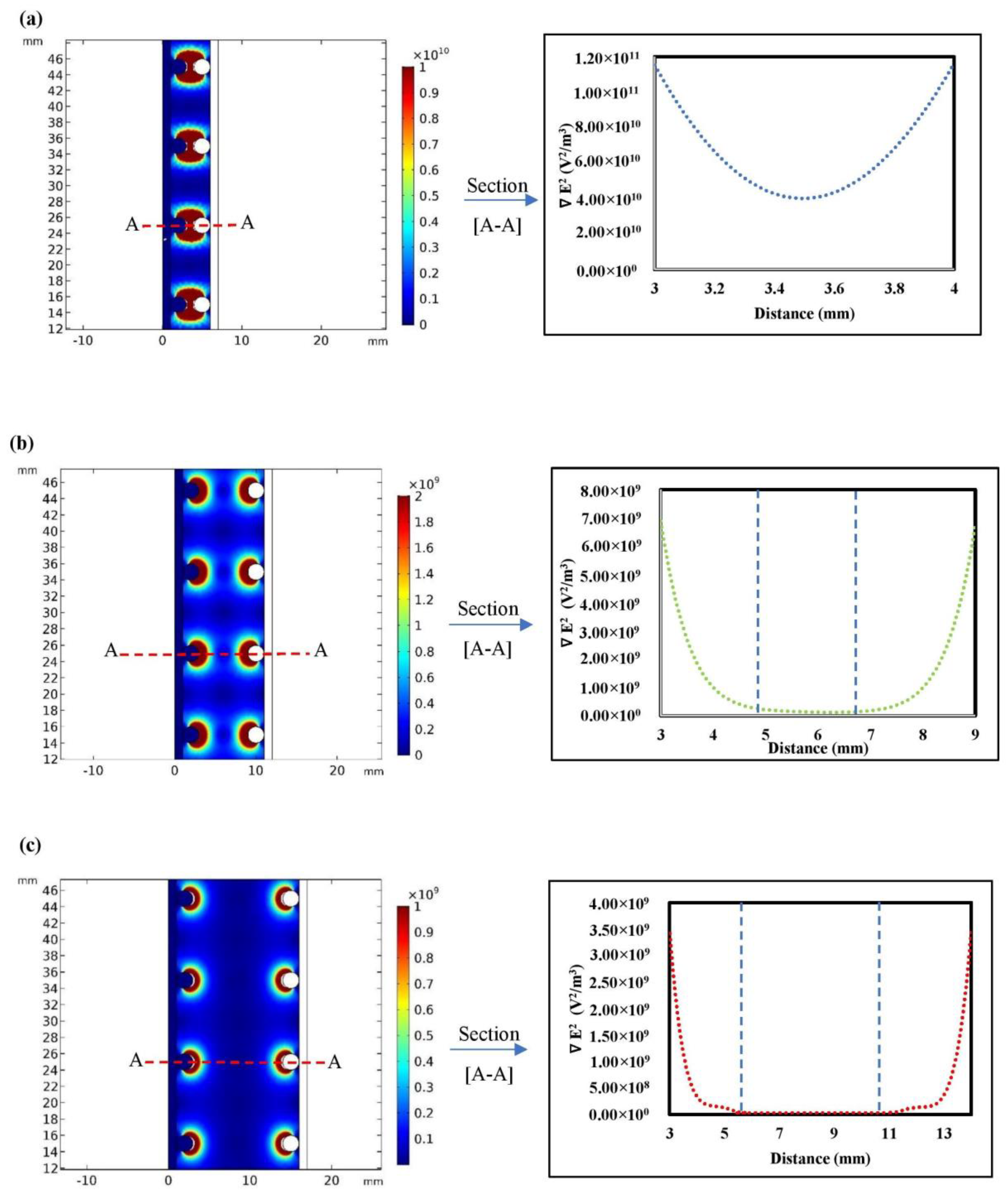
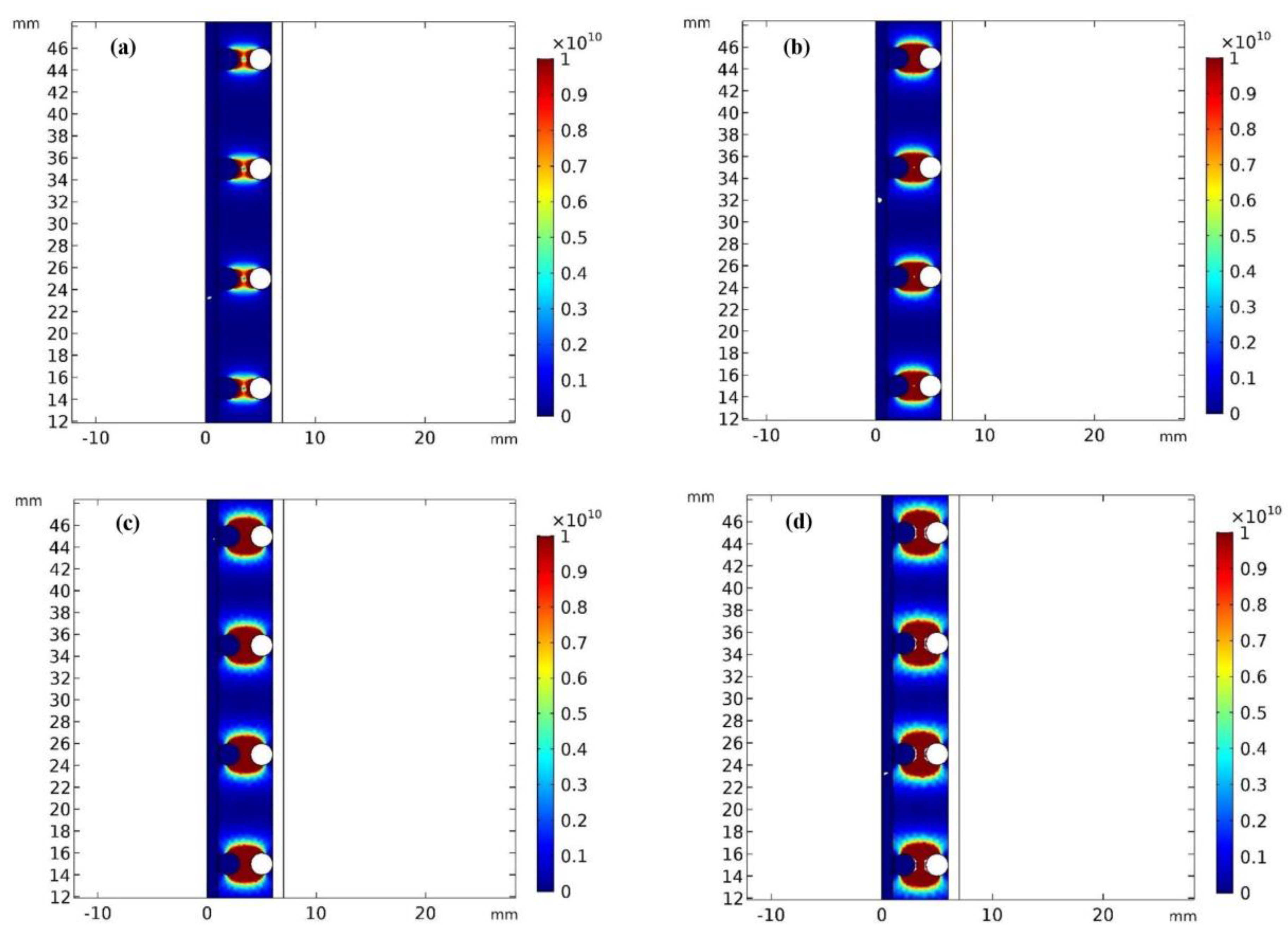
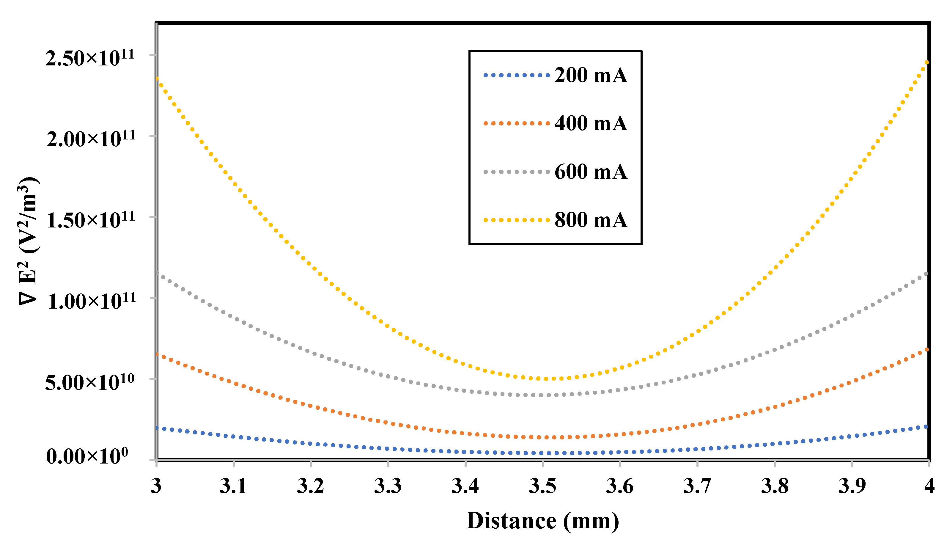
3.1. Numerical Simulation

3.1.1. Impact of the Electrode Spacing

The impact of electrode spacing on the DEP force was evaluated using three different electrodes spacings (i.e., 0.5 cm, 1 cm and 1.5 cm) at an applied current of 600 mA. Figure 4 shows that the DEP force presented by the electric field squared ( E 2 ) was the highest when the distance between the electrodes was 0.5 cm, compared to 1 cm and 1.5 cm. At an electrodes spacing of 0.5 cm, the maximum ∇E2 was 1.2 × 10¹¹ v2/m3 at the electrode surface, and the minimum ∇E2 was at the midpoint, with a value of 4.0 × 10¹⁰ v2/m3. At an electrodes spacing of 1.0 cm, the maximum ∇E2 was 7.0 × 10⁹ v2/m3 at the electrode surface, and it went down to zero at a distance 2 mm away from the electrode surface. It was also noticed that a zone with no DEP effect was present. The zone extended for a length of 2 mm. At an electrodes spacing of 1.5 cm, the maximum ∇E2 was 3.4 × 10⁹ v2/m3 at the electrode surface, and this went down to zero at a distance of 3 mm away from the electrode surface. It was also noticed that a zone with no DEP effect was present. The zone extended for a length of 5 mm.

3.1.2. Impact of the Applied Current

The impact of current density on the DEP force field was evaluated using four applied currents, 200 mA, 400 mA, 600 mA and 800 mA, corresponding to current densities of 5.71, 11.43, 17.14 and 22.86 mA/cm2, respectively. The electrode spacing was fixed at 0.5 cm. As shown in Figure 5, the DEP force field increased as the applied current increased. The DEP force field was minimal when using an applied current of 200 mA. However, the DEP force field affected a larger area when using an applied current of 400 mA, and became significant when using an applied current of 600 mA and 800 mA.
Figure 6 shows the impact of the applied current on the squared electric field. The electric field squared ( E 2 ) at the surface of the electrodes was almost 1.5 × 10¹⁰ v2/m3 using an applied current of 200 mA. The E 2 at the surface of the electrodes increased significantly, by 70%, when using an applied current of 400 mA. As the applied current increased to 600 mA, the E 2 increased by 36%, and was further enhanced by 54% at an applied current of 800 mA.

3.2. Experimental Study

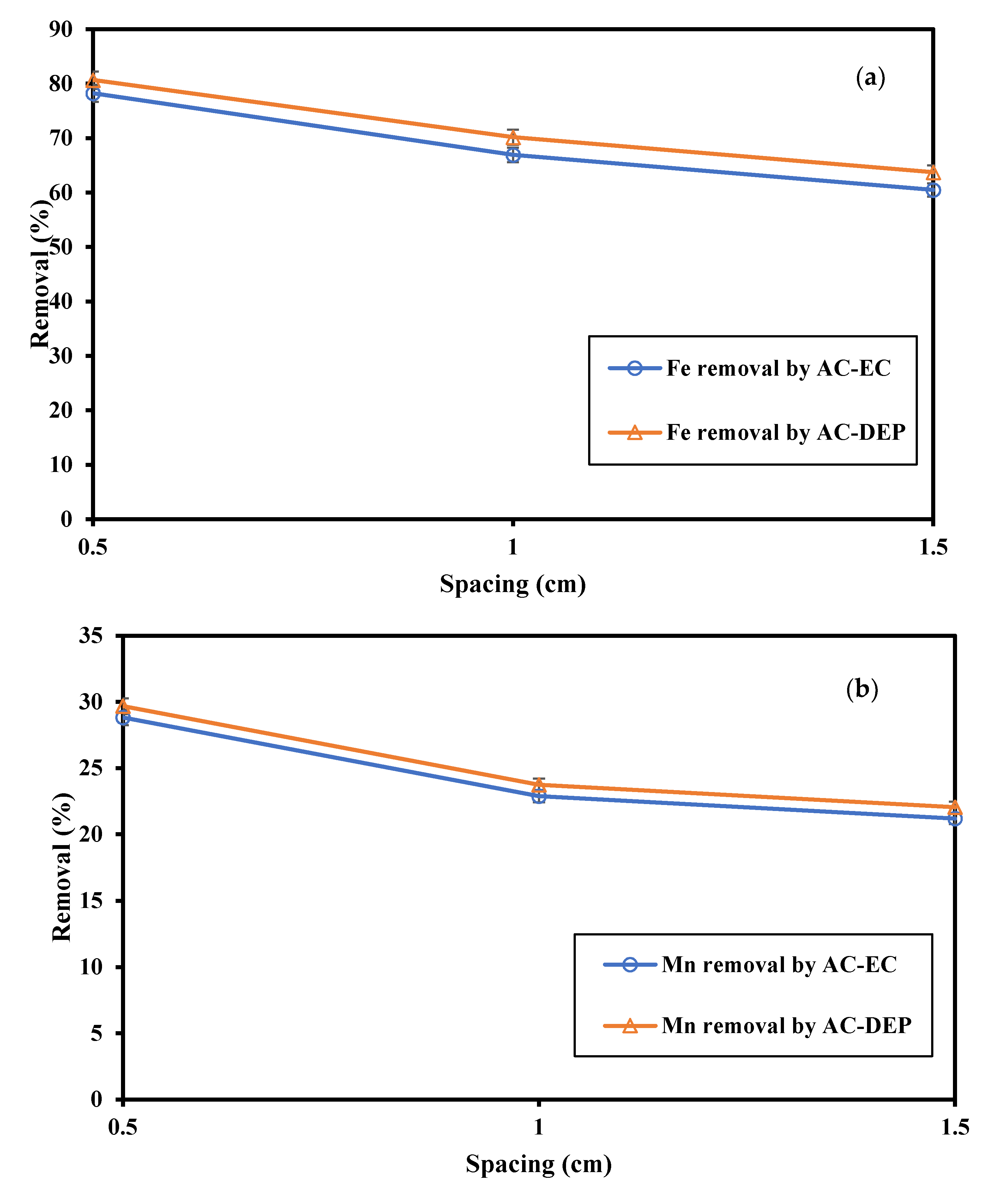
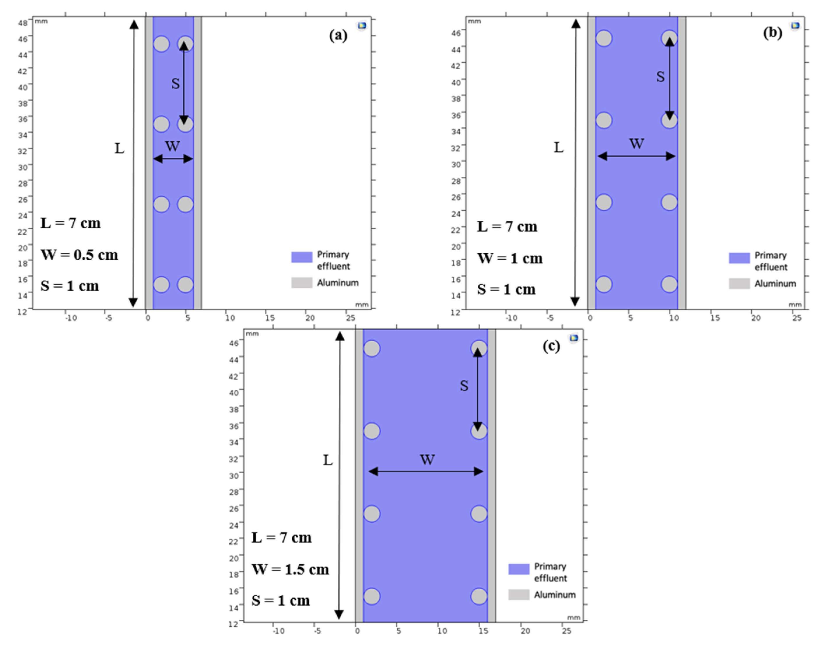
3.2.1. Impact of the Electrode Spacing

To evaluate the impact of electrode spacing, the applied current was fixed at 600 mA and the electrolysis time was 30 min. As shown in Figure 7a,b, the Fe and Mn removal percentage decreased as the electrode spacing increased using both the AC-EC and AC-DEP configurations. The Fe removal percentage using AC-DEP was slightly higher than with using AC-EC. At an electrode distance of 0.5 cm, the removal percentages of Fe using AC-EC and AC-DEP were 78.8% and 80.3%, respectively. The Fe removal percentage decreased by 12.5% as the electrode spacing increased to 1 cm using AC-EC and AC-DEP. The Fe removal percentage decreased by 9.1% as the electrode spacing increased to 1.5 cm using AC-EC and AC-DEP. The Mn removal percentage using AC-DEP was slightly higher than when using AC-EC. At an electrode distance of 0.5 cm, the removal percentages of Mn using AC-EC and AC-DEP were 28.8% and 29.6%, respectively. The removal percentage of Mn decreased by 19.9% as the electrode spacing increased from 0.5 cm to 1 cm, using both AC-EC and AC-DEP. The Mn removal percentage decreased by 4.9% as the electrode spacing increased from 1 cm to 1.5 cm using both AC-EC and AC-DEP. The maximum removal percentage of Fe and Mn was obtained using an electrode spacing of 0.5 cm. The removal percentage of Fe and Mn was lower at higher electrodes spacings due to the increase in the electrical resistance in the solution. Higher resistance would reduce the dissolution of coagulants from the electrodes, thus reducing the removal efficiency of pollutants in the system [21,22]. In addition, the enhancement of the removal percentage of Fe and Mn in the AC-DEP configuration compared to the AC-EC configuration could be due to the effect of the DEP force. The DEP force is expected to enhance the interaction between particles and the formation of flocs, and thus enhance the removal percentage of Fe and Mn. As the distance between the electrodes decreases, the DEP force increases and higher removal efficiencies of Fe and Mn are obtained. These results are compatible with the simulation results, where it was found that the DEP force was the highest at an electrode distance of 0.5 cm, and as the distance between the electrodes increased the DEP force decreased. In addition, from the simulation studies, it was found that at electrode distances of 1 cm and 1.5 cm, a zone of no DEP effect existed.

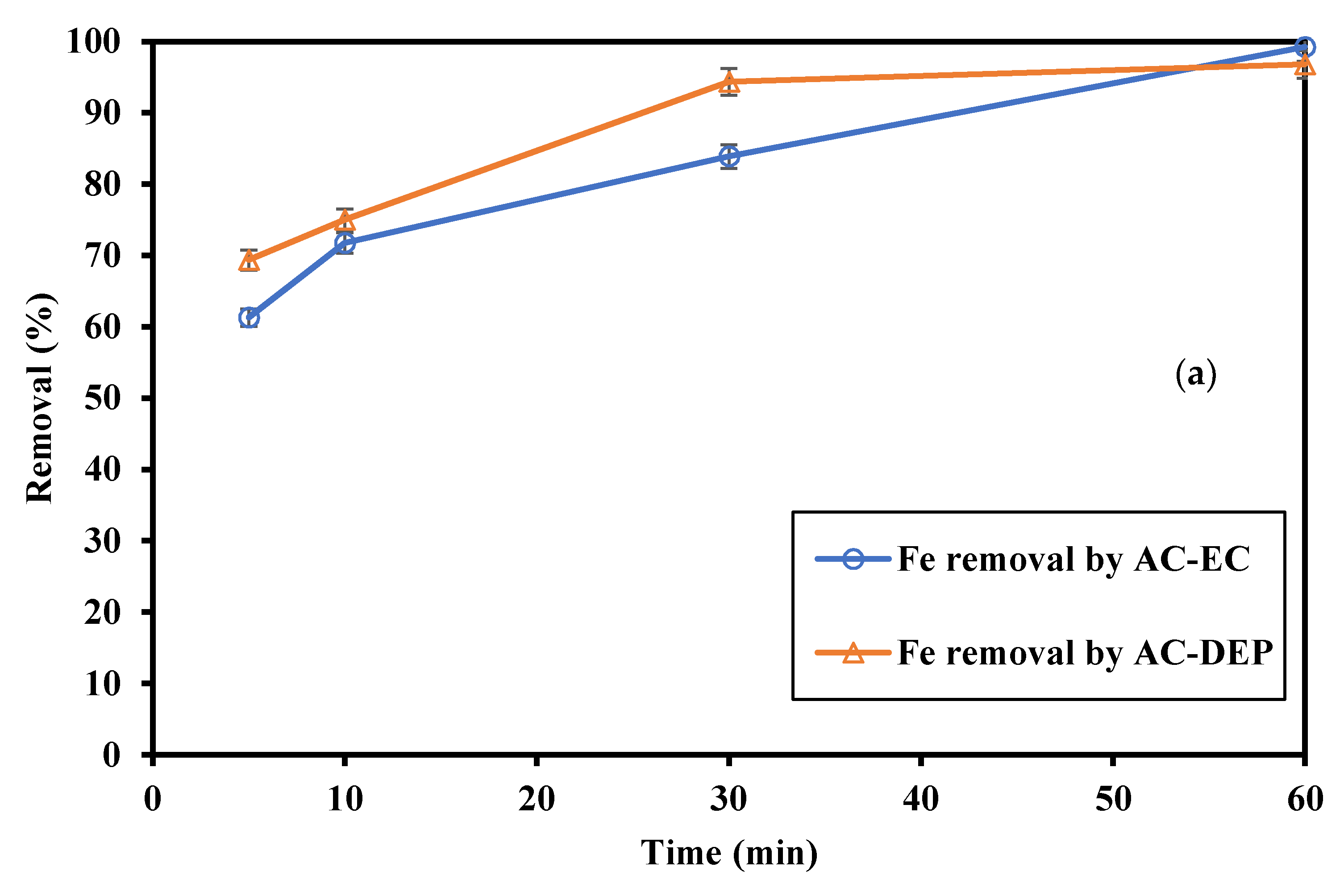
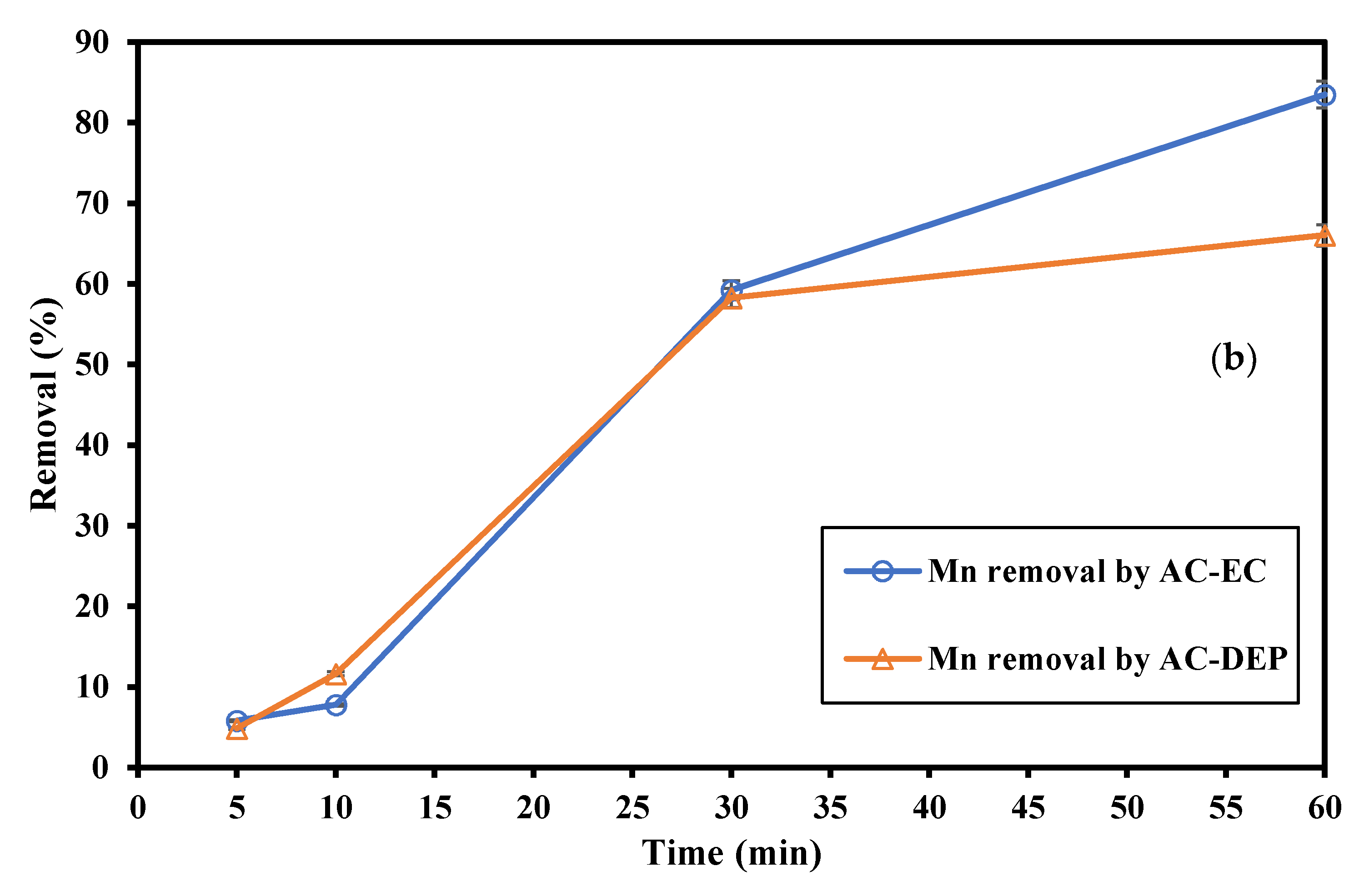
3.2.2. Impact of the Electrolysis Time

Electrolysis times of 5, 10, 30 and 60 min were investigated. The applied current and the electrode spacing were fixed at 800 mA and 0.5 cm, respectively. As shown in Figure 8a, the Fe removal percentage increased as the electrolysis time increased using both AC-EC and AC-DEP configurations. The removal percentage of Fe using AC-DEP was higher than when using AC-EC, where at an electrolysis time of 5 min, the removal percentages of Fe using AC-EC and AC-DEP were 61.3% and 69.3%, respectively. The Fe removal percentages increased by 14.7% (AC-EC) and 3.4% (AC-DEP) as the electrolysis time increased to 10 min. The Fe removal percentages increased by 14.5% (AC-EC) and 21.2% (AC-DEP) as the electrolysis time increased to 30 min. At an electrolysis time of 60 min, the Fe removal percentage increased by 15.4% using AC-EC, while the Fe removal percentage remained almost constant using AC-DEP. As shown in Figure 8b, the Mn removal percentage increased as the electrolysis time increased using both AC-EC and AC-DEP modes. At an electrolysis time of 5 min, the removal percentages of Mn using AC-EC and AC-DEP were almost the same, with a value of 5%. As the electrolysis time increased to 10 min, the Mn removal percentages increased by 35.5% (AC-EC) and 56.8% (AC-DEP). At an electrolysis time of 30 min, the Mn removal percentage increased significantly by almost 80% using both AC-EC and AC-DEP configurations. At the electrolysis time of 60 min, the Mn removal percentage increased by 30.1% using AC-EC and 13.2% using AC-DEP. The electrolysis time had a major influence on the removal efficiency of Fe and Mn in the EC process, as it will affect the amount of metal ions produced by the electrodes [23]. As the electrolysis time increases more ions will be produced, and so higher removal efficiencies were expected [23]. It can be seen from Figure 8a,b that the removal efficiency of Fe was higher than the removal efficiency of Mn. The higher removal efficiency of Fe could be attributed to the lower solubility of the formed iron hydroxides. The formation of manganese and iron hydroxides, and their precipitation, plays a dominant role in the removal mechanism of the corresponding metallic ions [9,24,25]. The solubility constants (Ksp) of manganese and iron hydroxides at 25 °C are 1.9 × 10⁻¹³ and 2.0 × 10⁻¹⁵, respectively. Figure 8a,b show that at an electrolysis time of 60 min, the removal efficiency of Fe and Mn in the AC-DEP configuration was less than that in the AC-EC configuration. This could be due to the fact that after a long period of DEP force application, the force could break the already-formed flocs and in turn reduce the removal efficiency.
It was found that with the increase in electrolysis time, the pH value increased using both AC-EC and AC-DEP configurations (Figure 9). Initially, the pH was 7.35, and it increased to 8.58 at an electrolysis time of 60 min for AC-EC and 8.18 for AC-DEP. It was observed that the final pH value for AC-DEP was always lower than the final pH value for the AC-EC, especially at a longer electrolysis time. The higher pH value is an indicator of the higher production of hydroxide ions at the cathode, and the higher corrosion of electrodes. Even though the production of hydroxide ions was higher in the AC-EC configuration, the removal efficiency in the AC-DEP configuration was higher for Fe and the same for Mn with a 30 min electrolysis time. This could indicate that the removal efficiency using the AC-DEP configuration was enhanced by the exertion of the DEP force. At an electrolysis time of 60 min, the removal efficiency of Mn using the AC-DEP configuration was almost 17% less than the removal efficiency of Mn using the AC-EC configuration. The higher pH value using the AC-EC configuration would decrease the solubility of the metal hydroxide; thus, a higher removal efficiency is expected.

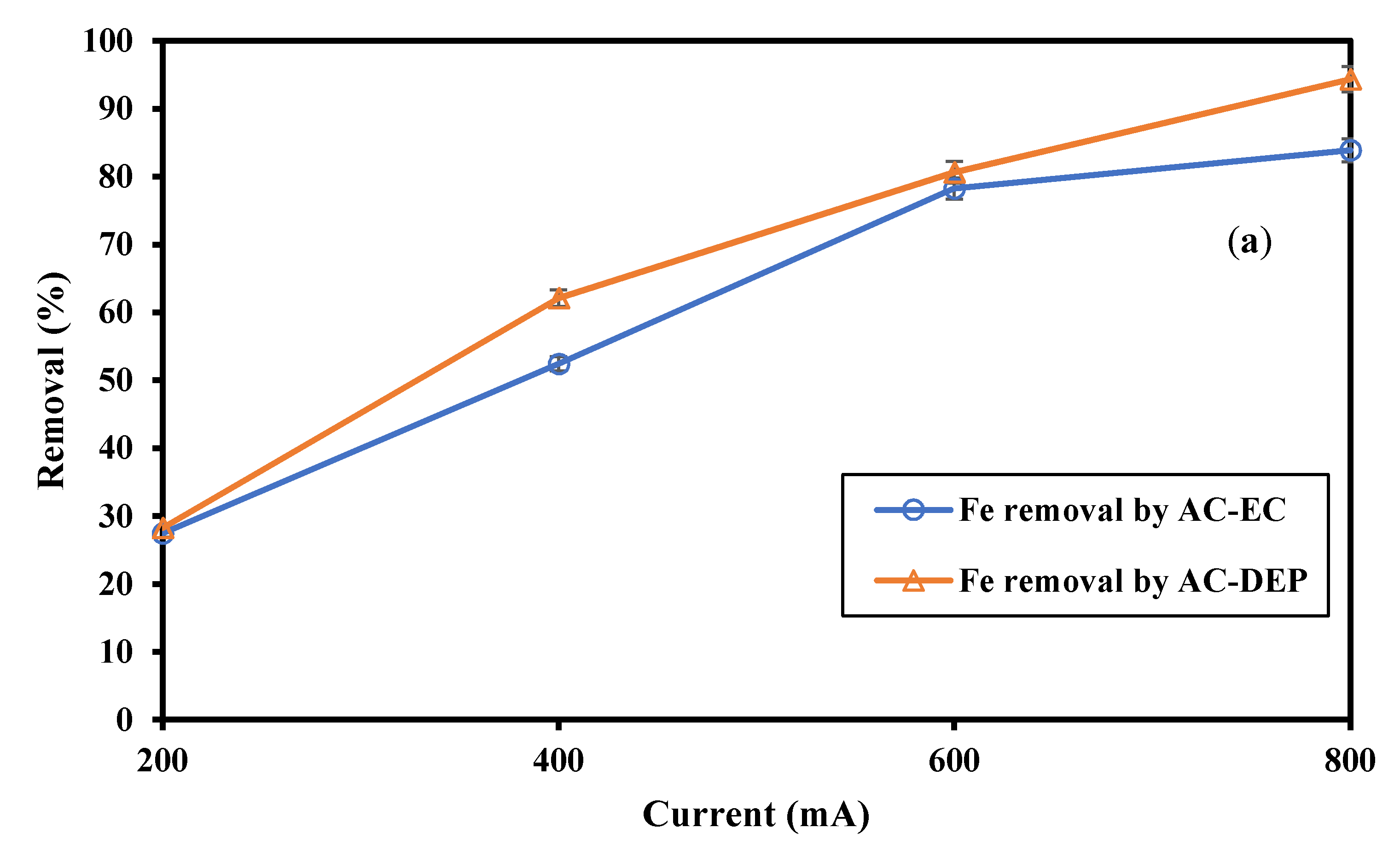
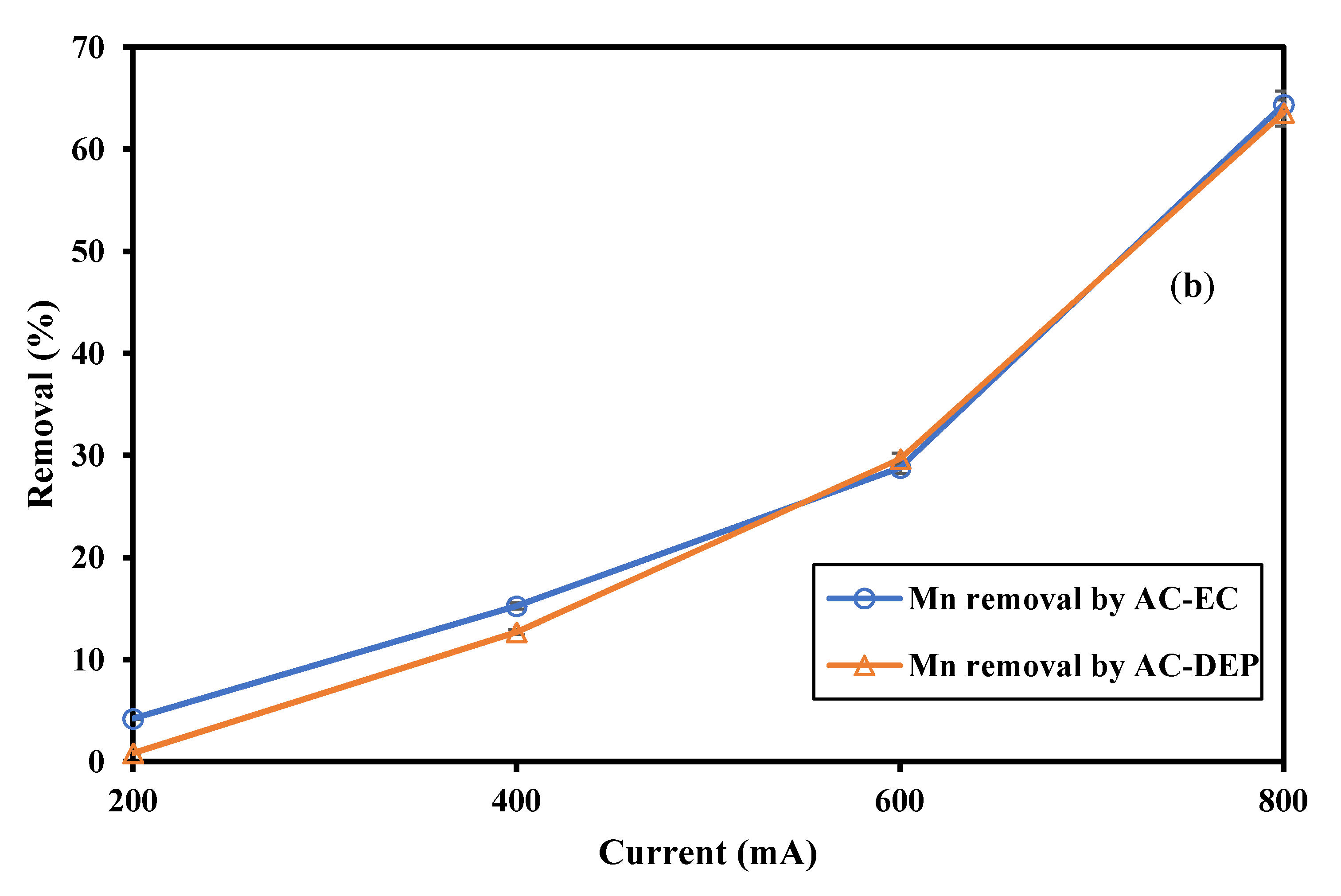
3.2.3. Impact of the Applied Current

Four different applied currents were tested: 200, 400, 600 and 800 mA, corresponding to current densities of 5.71, 11.43, 17.14 and 22.86 mA/cm2, respectively. The electrolysis time was fixed at 30 min and the electrode spacing was 0.5 cm. As shown in Figure 10, the removal percentages of Fe and Mn increased as the applied current increased. When using an applied current of 200 mA the Fe removal percentage was around 28% using both AC-EC and AC-DEP. The Fe removal percentage increased by 46.2% and 54.8% using an applied current of 400 mA compared to an applied current of 200 mA in the AC-EC and AC-DEP configurations, respectively. The Fe removal percentage increased to around 80% using an applied current of 600 mA in both the AC-EC and AC-DEP configurations. The maximum removal percentage of Fe was 94.3%, obtained using an applied current of 800 mA in the AC-DEP configuration. The removal percentage of Mn was 4.2% using an applied current of 200 mA in the AC-EC configuration. The Mn removal percentage increased by 72.3% and 93.3% using an applied current of 400 mA, compared to an applied current of 200 mA in the AC-EC and AC-DEP configurations, respectively. The Mn removal percentage increased to almost 30% using an applied current of 600 mA in both the AC-EC and AC-DEP configurations. The maximum removal percentage of Mn was 63.6%, obtained using an applied current of 800 mA in both the AC-EC and AC-DEP configurations. The production of Al3+ ions increases as the current density increases, due to the enhanced dissolution of the aluminum electrodes. Therefore, the amount of trapped heavy metal increased due to the increased amount of coagulants [26,27]. In addition, higher applied current means higher DEP force, as the DEP force is directly proportional to the applied voltage. Higher DEP force means greater interaction between particles, and hence more floc formation and higher removal efficiencies. Figure 11 illustrates the impact of the DEP force on the removal of heavy metals using the electrocoagulation process. The DEP force pushes the particles away from the electrodes exerting a negative DEP force. This force is expected to enhance the agglomeration of heavy metals, thus enhancing the removal efficiency. Moreover, the exertion of the DEP force would reduce the accumulation of flocs on the electrodes’ surfaces.
The main advantage of using the DEP-inducing electrodes lies not only in the enhanced removal efficiency, but also in the amount of consumed Al in the EC process. This can reduce the electrode consumption and the amount of aluminum species in the treated effluent. Figure 12 shows the aluminum content in the reactor with respect to the applied current. The aluminum content increased as the applied current increased, using both AC-EC and AC-DEP configurations. However, the aluminum content obtained using the AC-DEP configuration was much lower than with the AC-EC configuration. At an applied current of 400 mA, the aluminum content using AC-DEP was almost 31% less than with the AC-EC. As the applied current increased, the difference in aluminum content also increased. The aluminum content using AC-DEP was almost 42% less than with AC-EC at an applied current of 800 mA.

3.2.4. Energy Consumption

The energy consumption of the system was evaluated for the four different applied currents (i.e., 200, 400, 600 and 800 mA). The electrode spacing and electrolysis time were fixed at 0.5 cm and 30 min, respectively. As shown in Figure 13, the energy consumption increased as the applied current increased. When using an applied current of 600 mA, the energy consumption in the AC-DEP was 3.13 kWh/m3, which is 2% lower than with AC-EC, and at an applied current of 800 mA the energy consumption obtained using the AC-DEP was 4.88 kWh/m3, which is 3% lower than with AC-EC. The energy consumption was almost the same using AC-EC and AC-DEP configurations. The minimal differences in the energy consumption between the two configurations are due to the differences in the resistance in each system. The shape of the electrodes configuration affected the resistance in the system, thereby affected the amount of consumed energy.

4. Conclusions

In this study, a new electrocoagulation (EC) electrode configuration has been investigated for the removal of Fe and Mn from primary treated municipal wastewater. The effect of electrolysis time, electrodes spacing and current on the removal of Fe and Mn was investigated. The experimental results showed the following:
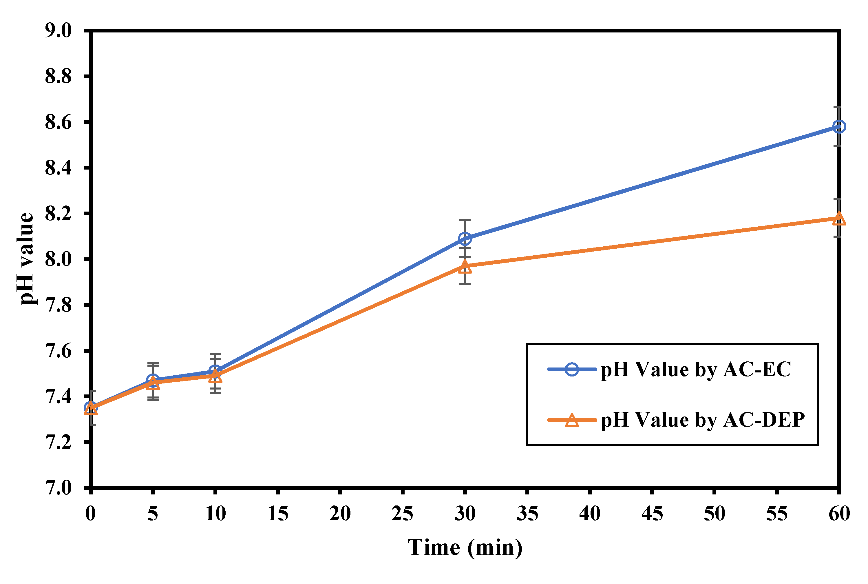
  • As the electrolysis time increased, the removal of Fe and Mn increased. As the electrolysis time increased more ions were produced, and so higher removal efficiencies were expected. The maximum removal percentages of Fe and Mn were obtained at an electrolysis time of 60 min. The removal of Fe was 99.2% using AC-EC and 96.8% using AC-DEP. The removal of Mn was 83.5% and 66% using AC-EC and AC-DEP, respectively;
  • As the distance between the electrodes decreased, the Fe and Mn removal increased. This was due to the decrease in the electrical resistance in the solution. A lower resistance would increase the dissolution of coagulants from the electrodes, thus increasing the removal efficiency of pollutants in the system. The maximum Fe and Mn removal was observed at an electrode distance of 0.5 cm;
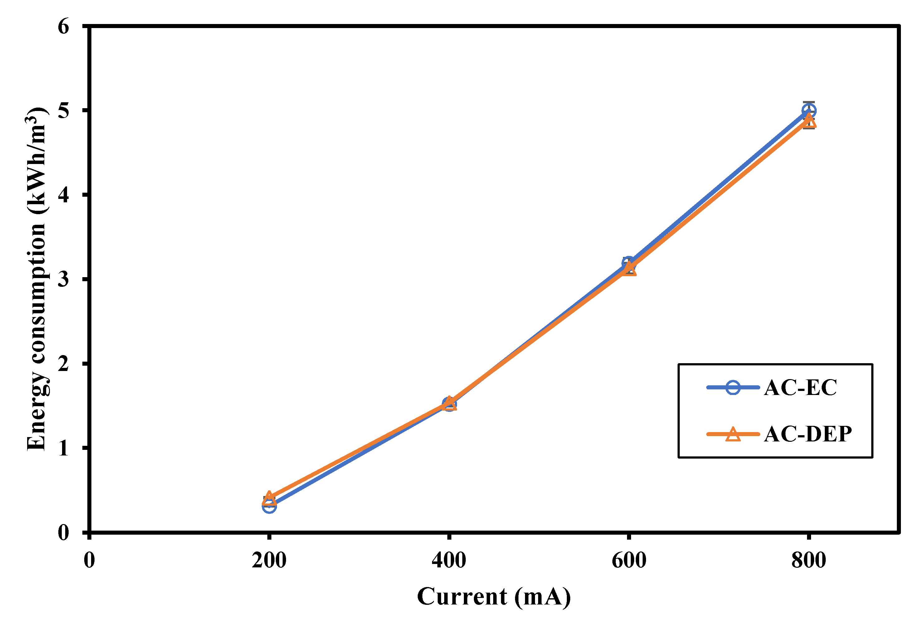
  • As the applied current increased, the removal efficiency increased. The production of Al3+ ions increased as the current increased due to the enhanced dissolution of the aluminum electrodes. Therefore, the amount of trapped heavy metal increased due to the increased amount of coagulants. The maximum Fe and Mn removal percentage was obtained at an applied current of 800 mA;
  • The applied current had the highest impact on the removal efficiency of Fe and Mn ions when using AC-EC and AC-DEP. As the applied current increased from 200 mA to 800 mA using AC-EC, the removal efficiencies of Fe and Mn increased by 56% and 60%, respectively. Similarly, as the applied current increased from 200 mA to 800 mA using AC-DEP, the removal efficiencies of Fe and Mn increased by 66% and 63%, respectively;
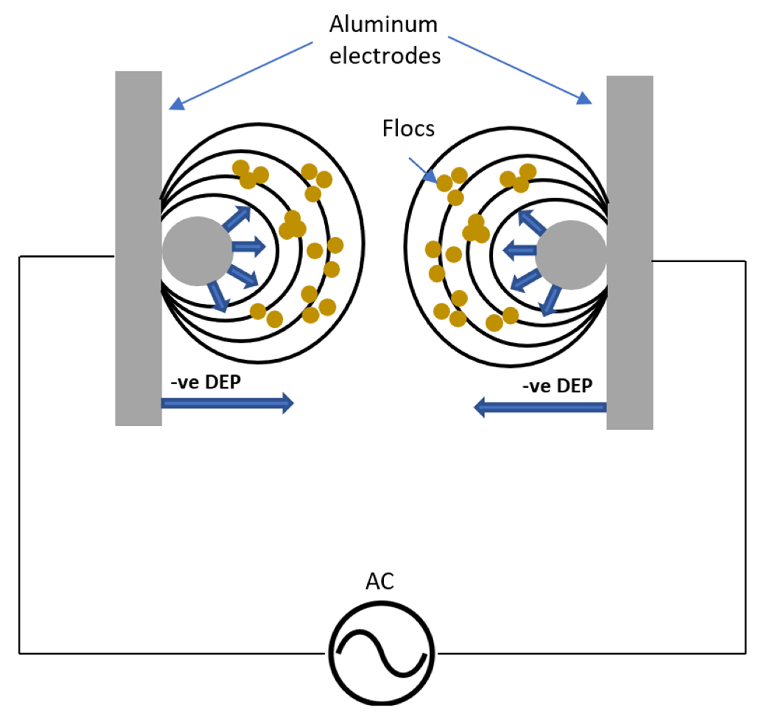
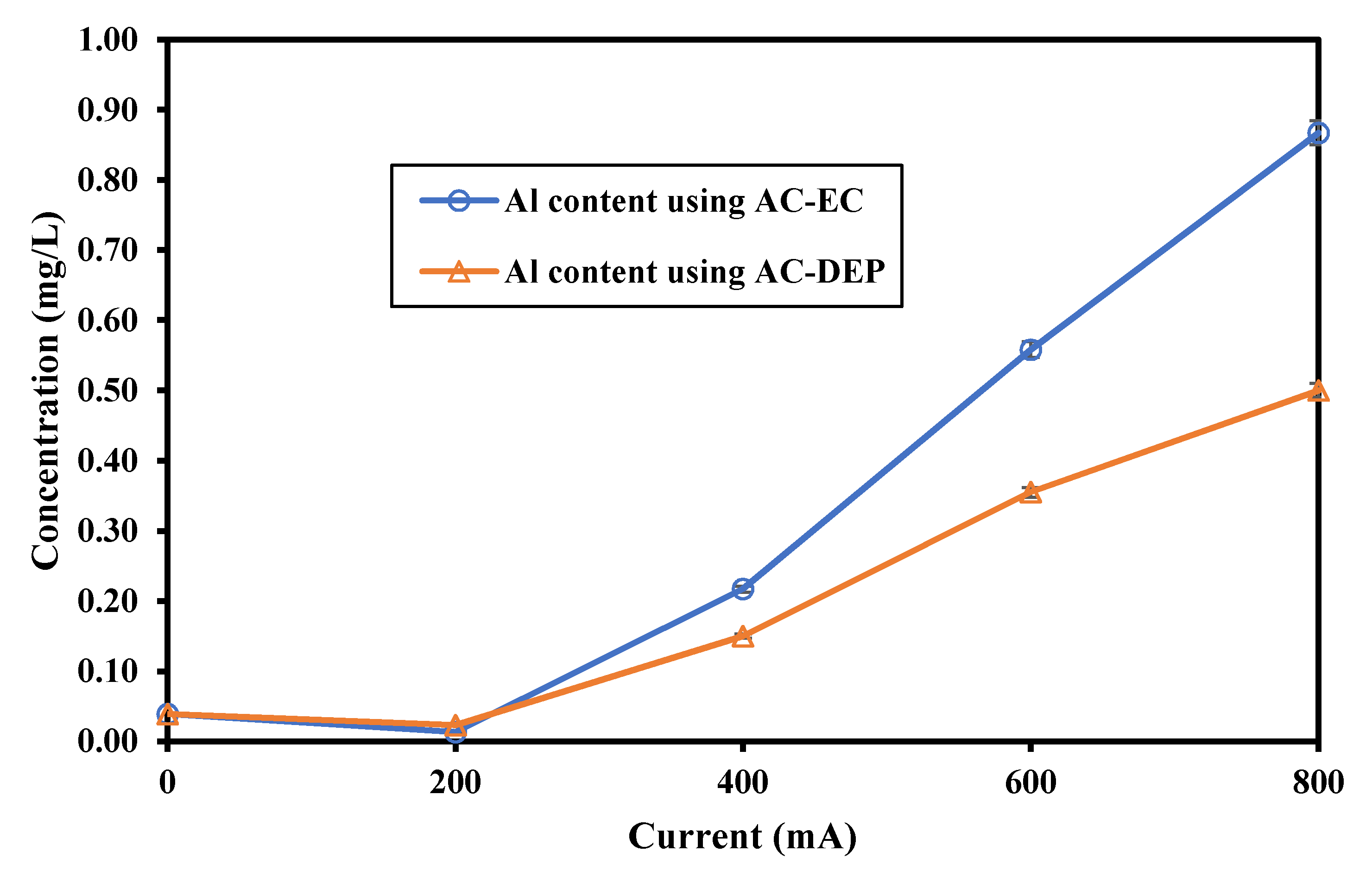
  • The main advantage of using the new DEP-inducing electrodes lies not only in the enhanced removal efficiency, but also in the amount of consumed Al in the EC process. The aluminum content increased as the applied current increased using both AC-EC and AC-DEP configurations. However, the aluminum content obtained using the AC-DEP configuration was much lower than with the AC-EC configuration. The aluminum content using AC-DEP was almost 42% less than the AC-EC at an applied current of 800 mA.

Author Contributions

Methodology, A.H.H. and M.H.; data curation, A.A. and M.H.; formal analysis, A.A., A.H.H. and M.H.; manuscript drafting, A.A.; manuscript review and edit: A.H.H. and M.H. All authors have read and agreed to the published version of the manuscript.

Funding

This project is funded by Qatar National Research Fund (QNRF) under Qatar Research Leadership Program—Graduate Sponsorship Research award (GSRA5-2-0525-18072) and (GSRA6-1-0509-19021).

Institutional Review Board Statement

Not applicable.

Informed Consent Statement

Not applicable.

Data Availability Statement

All data generated or analyzed during this study are included in this published article.

Acknowledgments

This research was made possible by Awards (GSRA5-2-0525-18072) and (GSRA6-1-0509-19021) from Qatar National Research Fund (a member of Qatar Foundation). The authors would like to thank the Central Laboratories Unit at Qatar University for the measurement of heavy metal. The authors also wish to thank Qatar Works Authority (Ashghal) for the supply of wastewater samples.

Conflicts of Interest

The authors declare no conflict of interest. The funders had no role in the design of the study; in the collection, analyses, or interpretation of data; in the writing of the manuscript, or in the decision to publish the results.

References

  1. Eyvaz, M.; Gürbulak, E.; Kara, S.; Yüksel, E. Preventing of cathode passivation/deposition in electrochemical treatment methods–a case study on winery wastewater with electrocoagulation. In Modern Electrochemical Methods in Nano, Surface and Corrosion Science; IntechOpen: London, UK, 2014. [Google Scholar]
  2. Uduman, N.; Bourniquel, V.; Danquah, M.K.; Hoadley, A.F.A. A parametric study of electrocoagulation as a recovery process of marine microalgae for biodiesel production. Chem. Eng. J. 2011, 174, 249–257. [Google Scholar] [CrossRef]
  3. Heidmann, I.; Calmano, W. Removal of Zn(II), Cu(II), Ni(II), Ag(I) and Cr(VI) present in aqueous solutions by aluminium electrocoagulation. J. Hazard. Mater. 2008, 152, 934–941. [Google Scholar] [CrossRef]
  4. Mollah, M.Y.A.; Schennach, R.; Parga, J.R.; Cocke, D.L. Electrocoagulation (EC)—Science and applications. J. Hazard. Mater. 2001, 84, 29–41. [Google Scholar] [CrossRef]
  5. Akbal, F.; Camci, S. Copper, chromium and nickel removal from metal plating wastewater by electrocoagulation. Desalination 2011, 269, 214. [Google Scholar] [CrossRef]
  6. Al Aji, B.; Yavuz, Y.; Koparal, A.S. Electrocoagulation of heavy metals containing model wastewater using monopolar iron electrodes. Sep. Purif. Technol. 2012, 86, 248–254. [Google Scholar] [CrossRef]
  7. Shafaei, A.; Rezaie, M.; Nikazar, M. Evaluation of Mn2+ and Co2+ removal by electrocoagulation: A case study. Chem. Eng. Process. Process Intensif. 2011, 50, 1115–1121. [Google Scholar] [CrossRef]
  8. Hanay, Ö.; Hasar, H. Effect of anions on removing Cu2+, Mn2+ and Zn2+ in electrocoagulation process using aluminum electrodes. J. Hazard. Mater. 2011, 189, 572–576. [Google Scholar] [CrossRef]
  9. Shafaei, A.; Rezayee, M.; Arami, M.; Nikazar, M. Removal of Mn2+ ions from synthetic wastewater by electrocoagulation process. Desalination 2010, 260, 23–28. [Google Scholar] [CrossRef]
  10. Das, D.; Nandi, B.K. Simultaneous removal of fluoride and Fe (II) ions from drinking water by electrocoagulation. J. Environ. Chem. Eng. 2020, 8, 103643. [Google Scholar] [CrossRef]
  11. Doggaz, A.; Attour, A.; Le Page Mostefa, M.; Tlili, M.; Lapicque, F. Iron removal from waters by electrocoagulation: Investigations of the various physicochemical phenomena involved. Sep. Purif. Technol. 2018, 203, 217–225. [Google Scholar] [CrossRef]
  12. Hashim, K.S.; Shaw, A.; Al Khaddar, R.; Pedrola, M.O.; Phipps, D. Iron removal, energy consumption and operating cost of electrocoagulation of drinking water using a new flow column reactor. J. Environ. Manag. 2017, 189, 98–108. [Google Scholar] [CrossRef]
  13. Das, D.; Nandi, B.K. Removal of Fe (II) ions from drinking water using Electrocoagulation (EC) process: Parametric optimization and kinetic study. J. Environ. Chem. Eng. 2019, 7, 103116. [Google Scholar] [CrossRef]
  14. Alkhatib, A.M.; Hawari, A.H.; Hafiz, M.A.; Benamor, A. A novel cylindrical electrode configuration for inducing dielectrophoretic forces during electrocoagulation. J. Water Process Eng. 2020, 35, 101195. [Google Scholar] [CrossRef]
  15. Hawari, A.H.; Alkhatib, A.M.; Das, P.; Thaher, M.; Benamor, A. Effect of the induced dielectrophoretic force on harvesting of marine microalgae (Tetraselmis sp.) in electrocoagulation. J. Environ. Manag. 2020, 260, 110106. [Google Scholar] [CrossRef]
  16. Hawari, A.H.; Alkhatib, A.M.; Hafiz, M.; Das, P. A novel electrocoagulation electrode configuration for the removal of total organic carbon from primary treated municipal wastewater. Environ. Sci. Pollut. Res. 2020, 27, 23888–23898. [Google Scholar] [CrossRef] [PubMed]
  17. Hawari, A.H.; Larbi, B.; Alkhatib, A.; Yasir, A.T.; Du, F.; Baune, M.; Thöming, J. Impact of aeration rate and dielectrophoretic force on fouling suppression in submerged membrane bioreactors. Chem. Eng. Process. Intensif. 2019, 142, 107565. [Google Scholar] [CrossRef]
  18. Hawari, A.H.; Du, F.; Baune, M.; Thöming, J. A fouling suppression system in submerged membrane bioreactors using dielectrophoretic forces. J. Environ. Sci. 2015, 29, 139–145. [Google Scholar] [CrossRef] [PubMed]
  19. Du, F.; Hawari, A.H.; Larbi, B.; Ltaief, A.; Pesch, G.R.; Baune, M.; Thöming, J. Fouling suppression in submerged membrane bioreactors by obstacle dielectrophoresis. J. Memb. Sci. 2018, 549, 466–473. [Google Scholar] [CrossRef]
  20. Du, F.; Hawari, A.; Baune, M.; Thöming, J. Dielectrophoretically intensified cross-flow membrane filtration. J. Memb. Sci. 2009, 336, 71–78. [Google Scholar] [CrossRef]
  21. Mohora, E.; Rončević, S.; Dalmacija, B.; Agbaba, J.; Watson, M.; Karlović, E.; Dalmacija, M. Removal of natural organic matter and arsenic from water by electrocoagulation/flotation continuous flow reactor. J. Hazard. Mater. 2012, 235–236, 257–264. [Google Scholar] [CrossRef] [PubMed]
  22. Sahu, O.; Mazumdar, B.; Chaudhari, P.K. Treatment of wastewater by electrocoagulation: A review. Environ. Sci. Pollut. Res. 2014, 21, 2397–2413. [Google Scholar] [CrossRef] [PubMed]
  23. Daneshvar, N.; Oladegaragoze, A.; Djafarzadeh, N. Decolorization of basic dye solutions by electrocoagulation: An investigation of the effect of operational parameters. J. Hazard. Mater. 2006, 129, 116–122. [Google Scholar] [CrossRef] [PubMed]
  24. Shafaei, A.; Pajootan, E.; Nikazar, M.; Arami, M. Removal of Co (II) from aqueous solution by electrocoagulation process using aluminum electrodes. Desalination 2011, 279, 121–126. [Google Scholar] [CrossRef]
  25. Adhoum, N.; Monser, L.; Bellakhal, N.; Belgaied, J.-E. Treatment of electroplating wastewater containing Cu2+, Zn2+ and Cr(VI) by electrocoagulation. J. Hazard. Mater. 2004, 112, 207–213. [Google Scholar] [CrossRef]
  26. Aoudj, S.; Khelifa, A.; Drouiche, N.; Hecini, M.; Hamitouche, H. Electrocoagulation process applied to wastewater containing dyes from textile industry. Chem. Eng. Process. Process Intensif. 2010, 49, 1176–1182. [Google Scholar]
  27. Gao, S.; Yang, J.; Tian, J.; Ma, F.; Tu, G.; Du, M. Electro-coagulation–flotation process for algae removal. J. Hazard. Mater. 2010, 177, 336–343. [Google Scholar] [CrossRef] [PubMed]
Figure 1. A schematic sketch of the electrocoagulation process.
Water 13 00485 g001
Figure 2. A schematic sketch for the bench-scale electrocoagulation setup used in this study.
Water 13 00485 g002
Figure 3. Illustration of the geometrical parameters of the simulated electrodes using three electrode spacings: (a) 0.5 cm, (b) 1 cm and (c) 1.5 cm.
Water 13 00485 g003
Figure 4. DEP force field (∇|E|2) using current of 600 mA and different electrodes spacings of (a) 0.5 cm, (b) 1 cm and (c) 1.5 cm.
Water 13 00485 g004
Figure 5. DEP force field (∇|E|2) using electrode spacing of 0.5 cm and different applied currents: (a) 200 mA, (b) 400 mA, (c) 600 mA and (d) 800 mA.
Water 13 00485 g005
Figure 6. Electric field squared using electrode spacing of 0.5 cm and different applied currents of 200 mA, 400 mA, 600 mA and 800 mA.
Water 13 00485 g006
Figure 7. The removal percentage of Fe and Mn using variable electrode spacing, electrolysis time of 30 min and applied current 600 mA. (a) Fe removal percentage; (b) Mn removal percentage.
Water 13 00485 g007
Figure 8. The removal percentage of Fe and Mn using variable electrolysis time, electrode spacing 0.5 cm and applied current 800 mA. (a) Fe removal percentage; (b) Mn removal percentage.
Water 13 00485 g008aWater 13 00485 g008b
Figure 9. The pH values using variable electrolysis time, electrode spacing 0.5 cm and applied current 800 mA.
Water 13 00485 g009
Figure 10. The removal percentage of Fe and Mn using variable applied current, electrolysis time 30 min and electrode spacing 0.5 cm. (a) Fe removal percentage; (b) Mn removal percentage.
Water 13 00485 g010aWater 13 00485 g010b
Figure 11. Schematic diagram of the impact of DEP force on the enhancement of flocs formation in the EC process.
Water 13 00485 g011
Figure 12. Aluminum content in the reactor using AC-EC and AC-DEP with 0.5 cm electrodes spacing and an operational time of 30 min.
Water 13 00485 g012
Figure 13. AC-EC and AC-DEP energy consumption using 30 min of operational time and 0.5 cm electrodes spacing on four different currents: 200, 400, 600 and 800 mA.
Water 13 00485 g013
Table 1. Previous studies and the present study on the removal of heavy metals using the electrocoagulation process and electrocoagulation-enhanced dielectrophoresis, respectively.
Feed WaterElectrodes NoElectrodes MaterialInitial Concentration (mg/L)Electrolysis Time (min)Current Density (mA/cm2)Electrodes Spacing (cm)Removal PercentageRef.
Metal plating3 setsAnode: Fe
Cathode: Al
Cu: 45
Cr: 44.5
Ni: 394
20101Cu: 100%
Cr: 100%
Ni: 100%
[5]
Model3 setsAnode: Fe
Cathode: Fe
Mn:250
Zn:250
Cu:250
Ni: 250
50250.3Mn: 72.6%
Zn: 96%
Cu: 96%
Ni: 96%
[6]
Synthetic solution1 setAnode: Al
Cathode: Al
Mn: 22.5606.21Mn: 39.6%[7]
Synthetic solution2 setsAnode: Al
Cathode: Al
Cu: 50–200
Zn: 50–200
Mn: 50–200
35150.5Cu:100%
Zn: 100%
Mn: 80–85%
[8]
Synthetic solution1 setAnode: Al
Cathode: Al
Mn: 100306.21Mn: 75%[9]
Drinking water1 setAnode: Al
Cathode: Al
Fe (II): 20
F: 10
604.311Fe (II): 100%
F: 96%
[10]
Groundwater1 setAnode: Al
Cathode: Al
Fe (II): 2520101Fe (II): >97%[11]
Drinking water2 setsAnode: Al
Cathode: Al
Fe (II): 20201.50.5Fe (II): 98.5%[12]
Drinking water1 setAnode: Al
Cathode: Al
Fe (II): 204521Fe (II):98.6%[13]
Municipal wastewater1 setAnode: Al
Cathode: Al
Fe (II): 0.124
Mn: 0.118
306022.860.5Fe (II): 94%
Mn: 66%
Present study
Table 2. Characteristics of primary treated municipal wastewater.
ParametersValueStandard Method
Temperature (°C)22.5   ±   0.3 APHA.2550 Temp
pH7.35   ±   0.01 APHA 4500-H+ B. Electro-metric Method
Turbidity (NTU)158   ±   2 APHA 2130 B. Nephelometric Method
Conductivity (mS/cm)2.20   ±   0.01 APHA 2510 B. Conductivity
Fe (mg/L)0.124   ±   0.001EPA Method 200.8
Mn (mg/L)0.118   ±   0.001
Al (mg/L)0.038   ±   0.001
Zn (mg/L)0.003   ±   0.001
Ni (mg/L)0.003   ±   0.001
Cu (mg/L)0.001   ±   0.001
Cd<LDL
Cr<LDL
Pb<LDL
Co<LDL
LDL: lower detection limit.
Table 3. Elemental composition of the aluminum alloy (Alloy-1070) used to fabricate the electrodes. The values indicate the maximum limits unless indicated as minimum.
ElementSiFeCuMnMgCrZnTiAl (min)
Wt. %0.20.250.040.030.03-0.040.0399.7
Publisher’s Note: MDPI stays neutral with regard to jurisdictional claims in published maps and institutional affiliations.

