4.3. Comparison and Analysis of Protective Measures for Different EDBs
In this study, in order to meet the overcurrent capacity of the highest point of the downstream pipeline, the water depth of the EDB is set as 3.26 m. A DN1000 EDV is connected in series in front of the box. It can be seen from
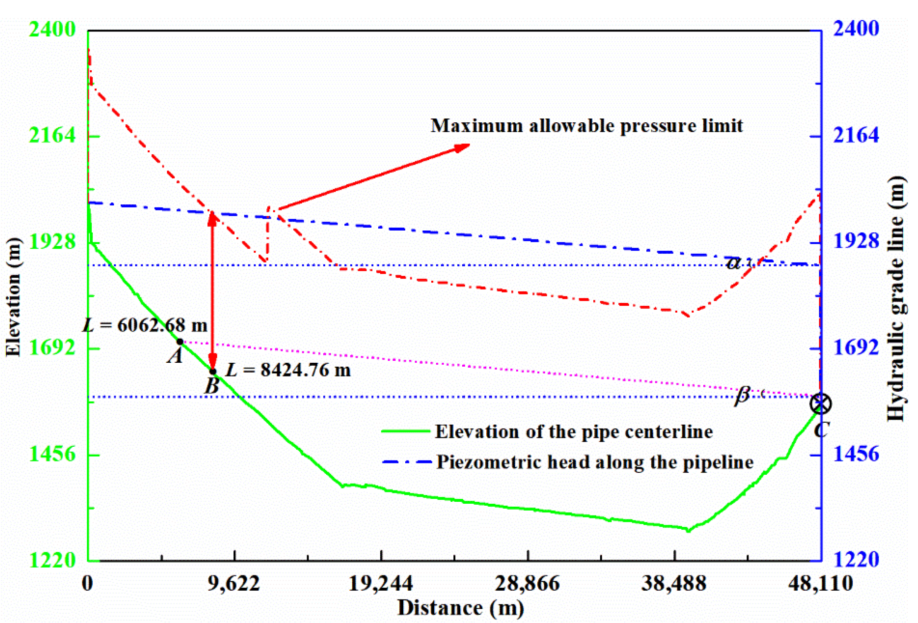
Figure 4 that the EDB is installed at point A (scheme
a), and the hydrostatic pressure head along the pipeline is much lower than the maximum working pressure head. Additionally, there is no negative pressure head along the pipeline, which meets the overcurrent capacity requirement of the pipeline. Firstly, the protection effect of schemes a and b (the EDB is installed at stake 20.064.00) is compared for the same size and valve closing time. Secondly, the protection effect of scheme
a is compared to that of scheme
c (the EDB is installed at stake 20.064.00) for different size parameters, and valve action and closing time. For the three schemes, the pressure reduction heads of the EDV are all 72.88 m. The valve opening and closing rules for the three schemes are shown in
Table 1 and
Table 2, and the extreme pressure head along the pipeline for the different schemes is shown in
Table 3. The parameters of the EDB and the bottom pressure head for the different schemes are compared in
Table 4, and the protective effects of water hammer for the three schemes are shown in
Figure 5,
Figure 6 and
Figure 7.
As the centerline elevations at the EDB location in the two schemes differ, the EDV and box in schemes
a and
b jointly reduce the heads by 288.77 m and 148.20 m, respectively. The EDV in front of the box is kept fully open and the pressure head is reduced by 72.88 m, and the pressure heads of the EDBs are reduced by 215.89 m and 75.32 m, respectively. As shown in
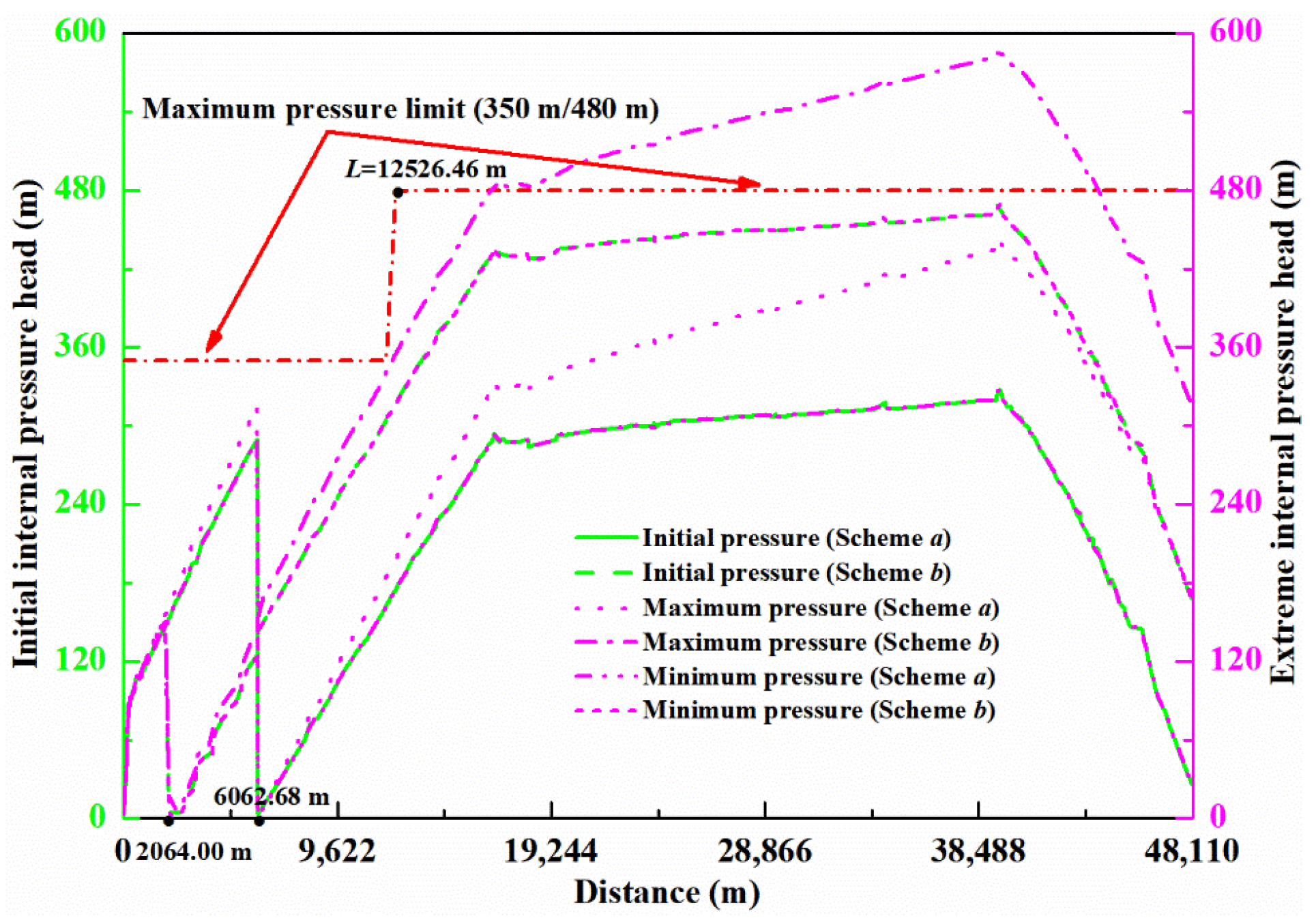
Figure 5, the initial internal pressure head in scheme
b is higher than that in scheme
a along the pipeline between 6062.68 m and 9915.76 m, while between 9915.76 m and the end of the pipeline, the initial internal pressure head in scheme
a is lower than that under scheme
b, because the EDB in scheme
a reduces the water heads more.
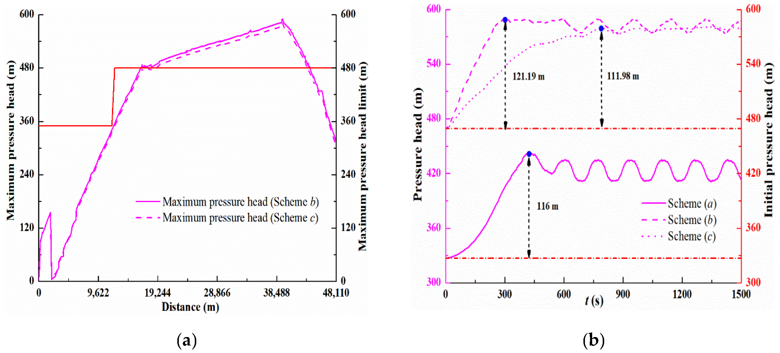
As listed in
Table 3, for the same size of EDB, the valve action and closing time of the maximum pressure heads of schemes
a and
b before the box are 315.92 m and 155.53 m, respectively, while the maximum pressure heads behind the box are 443.15 m and 590.35 m, respectively. In scheme
a, the difference between the maximum internal pressure head along the pipeline and the pipeline pressure head standard is |443.15 m − 480 m| = 36.85 m, and the maximum internal pressure head along the pipeline does not exceed the working pressure head of the pipeline. In scheme
b, the maximum pressure head along the pipeline from 16,553 m to 43,839.25 m exceeds the pipeline pressure head standard, and the maximum pressure head difference is 110.35 m (located at
L = 39,410.04 m, where the pipeline centerline elevation is the lowest). This is because the EDB in scheme
b is located near the upper reservoir, and the pressure head reduction under constant flow is 288.77 − 148.20 = 140.57 m less than that in scheme
a. As a result, the pressure head along the pipeline for the same valve closing time is higher than the internal water pressure head in scheme
a. In addition, there is no negative pressure head in the two schemes, which meets the overcurrent capacity requirement of the pipeline. Compared to scheme
b, the maximum/minimum pressure head in scheme
a is within the range of pressure head standard. Therefore, scheme
a can provide better water hammer protection, which illustrates further the usefulness of the optimal location theory of EDB.
As shown in
Table 3, the maximum pressure heads along the front pipe of the box in schemes b and c are 155.53 m and 154.95 m, respectively, and the maximum pressure heads along the pipe behind the EDB in schemes b and c are 590.35 m and 581.14 m, respectively. When the closing time of the valve increases (the closing time of the EDV is from 400 s to 800 s, for DN1200 end valve from 585 s to 1500 s, and for DN800 end valve from 415 s to 1500 s), the maximum pressure head along the pipeline in scheme c is higher than that in scheme a, but the pressure head is not significantly different.
As shown in
Figure 6a, the maximum pressure along the pipeline in scheme c also exceeds the maximum working pressure of the pipe between 1912.89 m and 43,451.81 m. In
Figure 6b, the maximum amplitudes of the maximum pressure head point along the pipeline behind the EDB in schemes a, b, and c are 116 m, 121.19 m, and 111.98 m, respectively. It is noted that after shutting the valve with a two-fold line, the maximum pressure amplitude of scheme c is 9.21 m lower than that of scheme b, and the pipeline pressure is alleviated, but the difference in the maximum pressure amplitude of the three schemes is very small. Therefore, in order to reduce further the pressure along the pipeline in scheme b, a longer valve closing time is needed. However, the longer the valve closing time, the lower the water level in the box, which entails higher requirements for the size of the EDB and increases the project cost. The initial internal pressure head along the back of the EDB in schemes b and c is higher than that in scheme a, and the maximum static pressure head difference along the pipeline is 142 m. Therefore, even if the valve closing time is further extended, the maximum pressure head along the pipeline will still exceed the pipeline pressure standard during valve closing in schemes b and c.
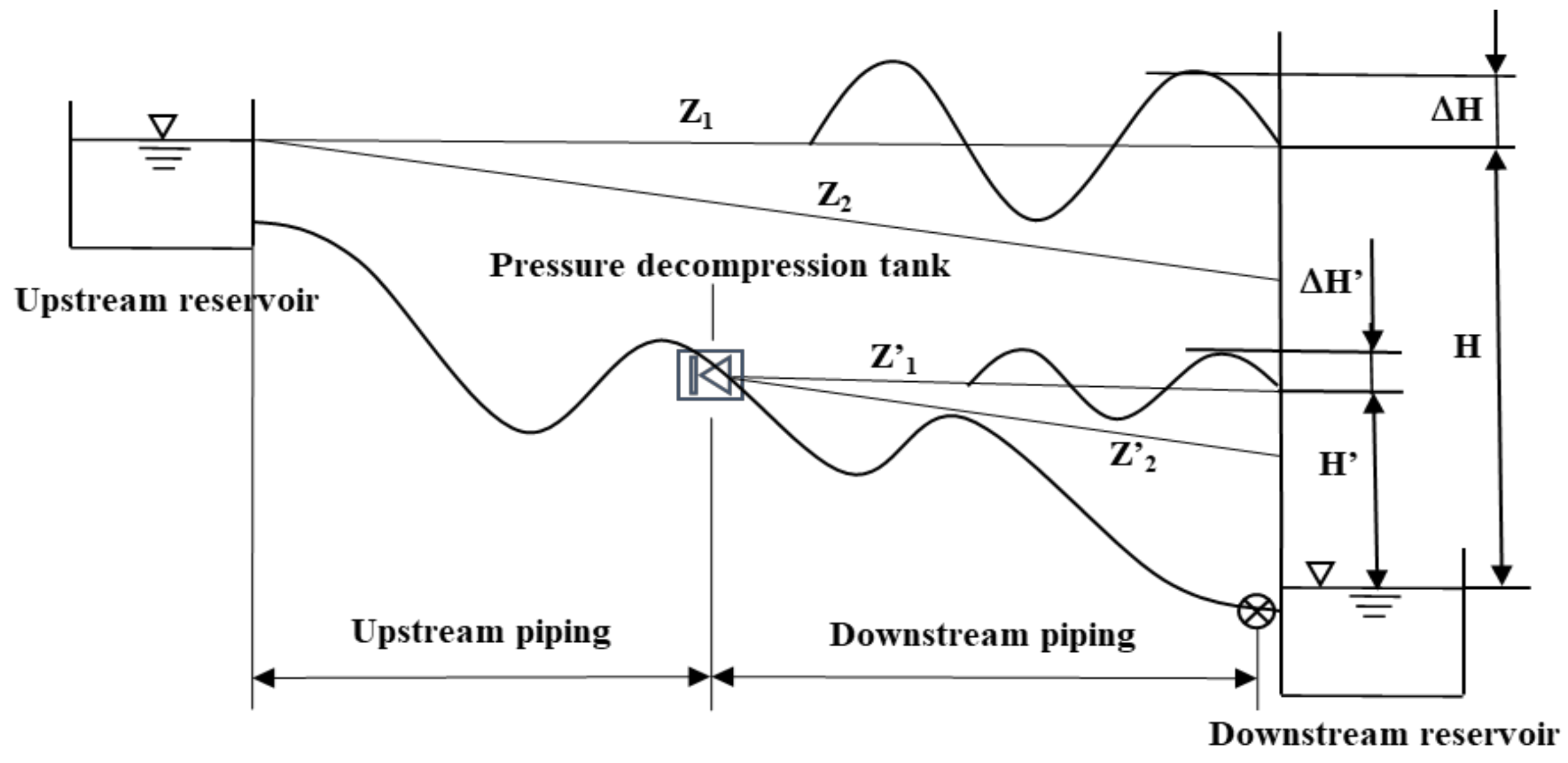
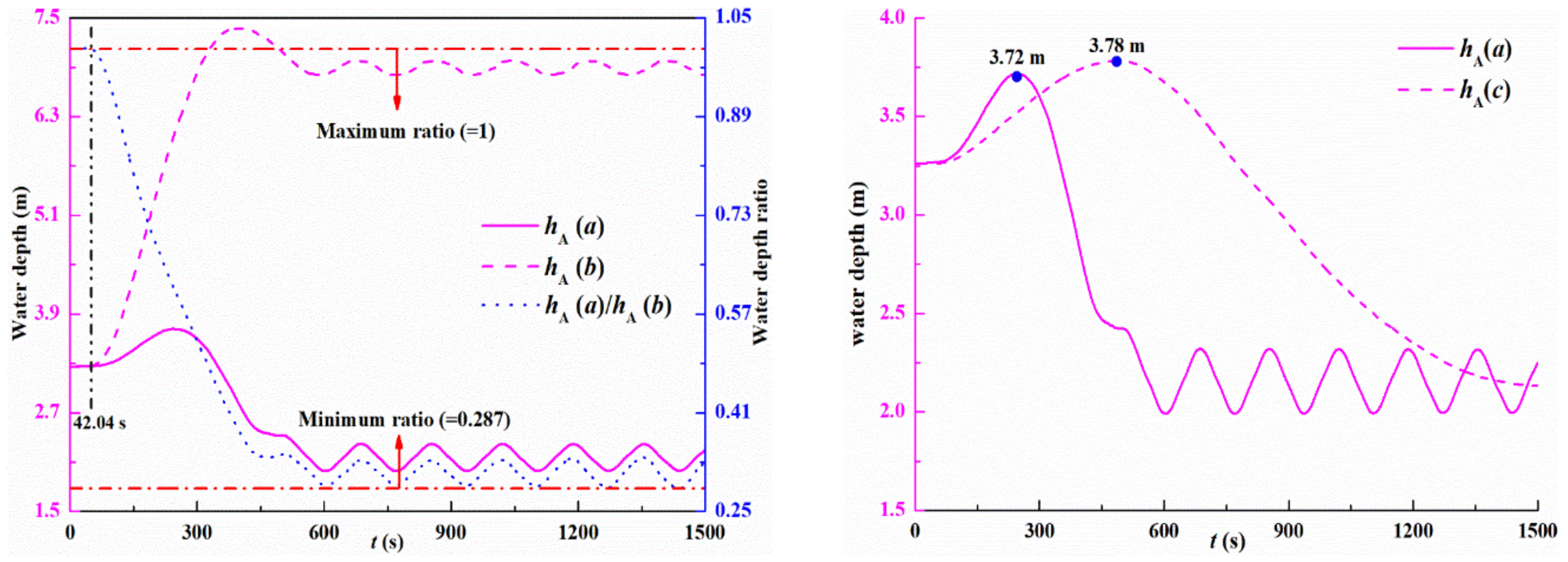
Figure 7 shows the change in water depth in the EDB for different locations. Due to the influence of valve action time, the water level of the EDB rises first and then decreases in the two schemes. As listed in
Table 4, the maximum water depth of the EDB in schemes a and b is 3.72 m and 7.37 m, respectively, and the lowest water depth is 1.99 m and 3.26 m, respectively. In the half length of scheme
a (
t =
L2/
c = 42,038.5/1000≈42.04 s), the water depth ratio of the EDB remains unchanged (=1) in the two schemes. From
t = 42.04 s, the downstream positive wave travels to the bottom of the EDB, and the water depth of the EDB in scheme a begins to fluctuate, resulting in a change in the water-depth ratio. The EDB location in scheme a is closer to the lower reservoir than in scheme b, i.e., distance
L2 is shorter. From Equation (13), it is noted that the closer the EDB is to the downstream reservoir, the smaller the water level fluctuation in the box and the larger the oscillation period. The amplitude of the water level in the EDB in scheme a is smaller than that in scheme b, as shown in
Figure 7a, and the fluctuation period of the water level in scheme
a is longer before the valve is completely closed. The theoretical analysis is consistent with the results of numerical simulations. After 42.04 s, the water depth ratio in the box continues to decrease until it stabilizes, and the minimum water depth ratio is 0.287. From the above analysis, it can be concluded that for the same valve closing rule, the water level fluctuation of the EDB in scheme
b is severer than in scheme
a and the requirements for the size of the EDB are higher.
As shown in
Table 4, the maximum water depth of the EDB in schemes
a and
c is 3.72 m and 3.78 m, respectively, the lowest water depth is 1.99 m and 2.13 m, respectively, and the cross-sectional area of the EDB in schemes
a and
c is 25 m
2 and 150 m
2, respectively. Therefore, after increasing the cross-sectional area of the EDB and increasing the valve closing time, the amplitude of the water level of the EDB located at 20.064.00 is not much different from that located at 60.062.68, as shown in
Figure 7b. It is noted from Equation (13) that the water level oscillation period is proportional to the cross-sectional area of the EDB, and the larger the area, the longer the oscillation period. The cross-sectional area of the EDB is inversely proportional to the water level amplitude: the larger the area, the slower the speed of the water body in the pressurized pipeline flowing in and out of the EDB, and the more stable the water level amplitude in the box. Compared to scheme
b, the maximum water depth in scheme
c decreased by 3.59 m. Therefore, in order to meet the requirements of alleviating the water level fluctuations of the EDB located at the front of the pipeline, it is necessary to increase the cross-sectional area of the EDB. However, at the same time, under the same requirements of water level amplitude protection, locating the EDB before the optimal location increases the project cost.


