Abstract
This paper demonstrates the application of multicriteria decision analysis (MCDA) methodology in a real case study aiming to choose the best rehabilitation intervention of an industrial water main. This methodology is composed of three main stages: problem identification, structuring, and evaluation. Problem structuring, a crucial stage for the outcomes, includes identifying objectives, selecting scenarios within the analysis period, defining problem alternatives, and defining the problematic type. Problem evaluation includes the selection of assessment metrics, selection of the aggregation method, application of the method, and a sensitivity and robustness analysis. Two scenarios, nine assessment metrics, and seven alternatives are established, and two ranking methods (the additive model and ELECTRE III method) are used to compare the alternatives. The results show that the best solution corresponds to building a new pipe and deactivating the existing one, as it significantly reduces the pipe failure risk and O&M costs, whereas the worst solution is always the status quo case, since it is the only alternative that does not improve the system performance, independently of the ranking method and the analyzed scenario.
1. Introduction
Urban water system (UWS) managers are facing the deterioration of the components of these systems and the need to proceed with rehabilitation in a scenario with limited funds for this purpose [1]. Rehabilitation interventions are necessary to maintain UWS performance and control the risks and costs related to service failures [2,3]. To better use limited funds, utility managers need to prioritize the rehabilitation interventions using criteria envisaging utility sustainability and quality of service [4,5].
The UWS rehabilitation decision process is challenging since most assets (i.e., pipes and sewers) are buried and difficult to inspect. Especially for water supply systems, water utilities must assess and predict the physical condition of the assets through indirect methods instead of direct techniques, such as visual inspection [6,7]. The condition assessment [8,9] takes into consideration the dimensions of performance, cost, and risk. This assessment strongly depends on reliable and organized data [10,11].
Traditionally, decisions on UWS rehabilitation interventions are based only on economic criteria, focused on the capital cost and the operation and maintenance (O&M) costs. The rehabilitation decision process of UWS based on a single point of view (e.g., cost analysis) is limited and found insufficient for decision making [12]; important aspects to include are the system’s performance, the risk of failures, and the whole life cost of the system infrastructure.
Nowadays, decision makers acknowledge the importance of integrating different points of view (e.g., performance and risk), considering the perceptions of the utility, stakeholders, and society, thus adding complexity to the decision-making process. The objectives of increasing performance while reducing risk and cost can conflict. Thus, the aggregation of criteria and metrics of different dimensions can significantly benefit from multicriteria decision analysis (MCDA).
MCDA helps to find solutions for actual problems with contradictory points of view [12,13]. The multicriteria problem is related to the methods and procedures by which criteria, points of view, and perspectives can be formally incorporated into the decision process. These problems fall into the categories of multi-attribute (discrete problems) or multi-objective problems (continuous problems) [13].
This paper describes the application of a method of MCDA proposed in Carriço et al. [1] to a case study of rehabilitation of an industrial water transmission main. The method has three main stages: problem identification, structuring, and evaluation. Problem structuring is a crucial stage for the outcomes. It includes identifying objectives, selecting scenarios within the analysis period, and defining problem options and the problematic type. Problem evaluation comprises the selection of assessment metrics, choice of an aggregation method, application of the method, and a sensitivity and robustness analysis. The results support the final recommendations. This application allowed for the identification of novel aspects and limitations resulting from the application of MCDA methodologies.
2. Data and Methods
2.1. Case Study Description
The industrial water supply system has water abstraction from a river and comprises collection, conveyance, treatment, storage, and water distribution components. The case study only focuses on the water transmission main between the water treatment plant and the storage tank upstream of the water distribution network. The pipe is made of prestressed concrete with a steel core, has ca. 10 km length, and diameters of DN 1500 (≈7.3 km), DN 1200 (≈0.5 km), and DN 1000 (≈2.0 km). The water main has gravity flow and has a maximum conveyance capacity estimated at 1.3 m3/s (i.e., ca. 40 × 106 m3/year.). The system has been in service continuously since 1980, and its current condition is unknown. The storage tank is composed of two rectangular cells with a capacity of 25,000 m3 each.
The water distribution network has a total extension of ca. 17 km, with diameters ranging from DN 110 to DN 800 of different materials, namely, asbestos cement (ca. 32%), fiberglass-reinforced polyester (ca. 26%), polyvinyl chloride (ca. 18%), and high-density polyethylene (ca. 24%).
2.2. Structure of the Methodology
The methodology is divided into three main stages: (i) problem identification; (ii) problem structuring; and (iii) problem evaluation, as shown in Figure 1. Problem structuring is a crucial stage for the outcomes. It includes identifying objectives, selecting scenarios within the analysis period, and defining problem options and the problematic type. Problem evaluation comprises the selection of assessment metrics, choice of an aggregation method, application of the method, and a sensitivity and robustness analysis.
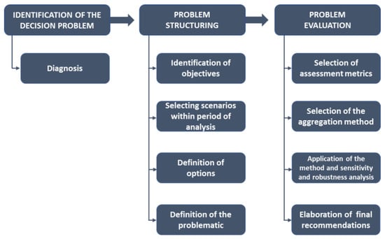
Figure 1.
MCDA methodology [1].
2.3. Identification of the Decision Problem
The identification of the decision problem in the context of infrastructure asset management planning is, generally, made during the diagnosis phase. The preliminary diagnosis allowed for the identification of several deficiencies in the water main that justify the need for urgent rehabilitation interventions in the short term. However, such rehabilitation intervention cannot interrupt the supply service to the industrial park, as it will interrupt the manufacturing activities, bringing substantial financial and economic losses for those industries. The water main has the following deficiencies:
- From the hydraulic point-of-view, this pipe has a maximum flow rate of 40 × 106 m3/year., which is insufficient for satisfying the water demand of new industries that may settle in the industrial park.
- From the structural point of view, the current condition is unknown, as it has been in operation for over 30 years and has never been taken out of service and inspected. However, there are records of some failures that never caused water supply disruptions, such as non-operating valves and small localized bursts in the steel sections of the water main inside the valve chambers. The pipe has signs that indicate an unsatisfactory condition in some areas, mainly where high vegetation growth is observed, indicating the existence of leakage.
- Regarding the satisfaction of the water distribution network located downstream, it is necessary to increase storage capacity.
The diagnosis has shown the need for rehabilitation of the water main due to the predictable water demand increase in the short and medium term, pipe aging, and unsatisfactory functional performance. The rehabilitation interventions will allow us to meet new service quality requirements and to ensure service efficiency, even in hard operating conditions. The water utility also has the concern of the lack of redundancy of the water main, which will threaten the water supply to the industrial park if a serious failure event occurs in the transmission main (e.g., pipe burst).
2.4. Problem Structuring
2.4.1. Identification of Objectives
The objectives considered relevant to this case study are the following:
- Ensure infrastructural sustainability and integrity.
- Ensure compliance with regulatory and contractual requirements related to water supply failures.
- Ensure the economic and financial sustainability of the water utility service.
2.4.2. Selecting Scenarios within the Period of Analysis
In the short to medium term, the industrial park is expected to expand, which will increase water demand. The current water consumption is about 10 × 106 m3/year, which is expected to double in the medium term (i.e., 20 × 106 m3/year). This quantity may be exceeded since the uncertainty regarding the real evolution of industrial water demand is very high. Thus, two scenarios for the evolution of industrial water demand are considered. The first (Scenario 1) corresponds to an increase from 20 × 106 to 50 × 106 m3/year. in 2030, and the second scenario (Scenario 2) corresponds to a reduction from 20 × 106 to 10 × 106 m3/year. in 2035. The second scenario is a pessimistic future vision where an economic crisis may happen or a more effective politic for energy transition is carried out, which may lead to the closure of several industries, which implies water demand reduction. So, in this scenario, profound changes in the industries’ profiles in the park are considered for ones with less water need. These scenarios were established together with the water utility. The analysis period was limited to 20 years because of the high uncertainty related to the water demand involved.
2.4.3. Definition of Options
The rehabilitation interventions for the industrial water main aimed at the following: (i) increasing system reliability by removing or reducing pipe structural deficiencies, (ii) ensuring the expected hydraulic capacity in the long term, and (iii) creating redundancy in the system whenever possible. Accordingly, the considered rehabilitation alternatives (options) are as follows:
- A0: keeping the status quo situation, in which no rehabilitation interventions are carried out in the water main, maintaining the current O&M practices, and maintaining the maximum hydraulic capacity of the system (ca. 40 × 106 m3/year.).
- A1: the installation of a new pipe in parallel with the existing one, designed to convey ca. 20 × 106 m3/year., and the rehabilitation of the existing pipe.
- A2: the installation of a new pipe in parallel with the existing one, designed to convey ca. 50 × 106 m3/year., and the deactivation of the existing pipe.
- A3: the installation of a new pipe with a different layout, designed to convey ca. 20 × 106 m3/year., the construction of a new storage tank in a new location with a total capacity of 25,000 m3, and the rehabilitation of the existing pipe.
- A4: the same as A3 but considering a total capacity of only 5000 m3 for the new storage tank.
- A5: the same as A3 but considering a new pipe with a different layout.
- A6: the same as A4 but considering a new pipe with a different layout.
The schematic of the pipe layout for each analyzed solution is presented in Figure 2.
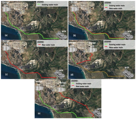
Figure 2.
Pipe layouts for alternatives: (a) A0, (b) A1, (c) A2, (d) A3 and A4, and (e) A5 and A6.
Rehabilitation of the Existing Pipe
The pipe anomalies are expected to be located, mostly, at the pipe joints (damaged sealing rings) and steel coils (broken). Additionally, all metallic parts and equipment inside the valve chambers should be replaced. The water utility aims to rehabilitate each joint with the installation inside the pipe of rubber “amex” type joints, or with joints of fiberglass or carbon. Considering that all joints would need rehabilitation and that in 9750 m of pipe there will be about 3250 joints (since each pipe has 3 m), the estimated cost of this intervention is about EUR 2,900,000. The replacement of equipment and metal parts inside the valve chambers, and the construction of new valve chambers, as the existing ones are insufficient, may have an additional cost estimated at around EUR 850,000. Considering these costs and the unforeseen or imponderables, the total rehabilitation cost of the existing pipe is estimated to be EUR 4,500,000.
2.4.4. Definition of the Problematic
Since the water utility aims to identify which is the best rehabilitation intervention alternative for the industrial water main, the expected result can either be the choice of the best alternative or the ranking of the different alternatives. However, the utility prefers to have a ranking of the alternatives; thus, only this problematic is considered to assess the present decision problem.
2.5. Problem Evaluation
2.5.1. Evaluation Phases
The rehabilitation interventions will be carried out at different stages to avoid water supply disruptions. The preliminary design and the final design phases would have a total duration of about two years from the end of 2021. After that, the building phase will take about two years with the new pipes entering in service in 2025, when the existing pipe will be placed out of service for rehabilitation until 2027. The assessment phase starts at the end of the building phase and ends in the horizon year of 2050, as shown in Figure 3.

Figure 3.
Evaluation phases considered in this decision problem.
2.5.2. Selection of Assessment Metrics
In this case study, nine metrics are considered to evaluate the alternatives that have been selected in collaboration with water utility experts.
Hydraulic Capacity Adequacy
The hydraulic capacity metric measures the ratio between maximum water volume that can be transported by the water main system in a certain period and the water volume that is effectively needed, as follows:
where is the hydraulic capacity at time t (-), t is the time (year), is the maximum volume of water transported by the system at time t (m3/year.), and is the predicted volume of industrial water demand at time t (m3/year.).
If than the pipe is overdesigned in terms of hydraulic capacity, if than the pipe hydraulic capacity is adequate to demand and if than the pipe is underdesigned.
System Storage Capacity
System storage capacity (M2) is defined by the ratio between the installed full storage capacity and the projected industrial water demand. Equation (2) shows the formula to obtain this metric.
where is the system storage capacity at time t (days), t is the time (year), is the maximum storage capacity installed by the system at time t (m3.), and is the average flow rate (m3/day).
Infrastructure Value Index
The infrastructure value index (IVI) represents the ratio between the current value and the replacement costs of the infrastructure [14,15,16]. IVI is assessed by Equation (3) [14].
where is the IVI at time t (-), t is the time (year), N is the total number of assets (-), is the replacement cost of asset i at time t (EUR), is the residual useful life of asset i at time t (years), and is the expected useful life of asset i (years). The IVI should ideally be near 0.5 (0.4–0.6).
When applied to a single component, the IVI simplifies and may be replaced by the percentage of residual life, which represents the ratio between the residual life (i.e., the amount of asset remaining life) and the expected service life (i.e., the amount of time an asset is expected to be functional). The percentage of residual life is given by Equation (4) [17].
where is the ratio of residual life at time t (-), t is the time (year), is the residual useful life of asset i at time t (years), and is the expected useful life of asset i (years).
Real Water Losses
The real water losses represent the amount of water wasted in leaks (m3) per unit of time (day) and per unit of pipe length (km). Since there are no available data to quantify the real losses in the industrial water main, the methodology proposed by [18] is used to estimate this value. The methodology is based on statistical data collected over 15 years in 25 countries. This metric can be assessed using Equation (5) [18].
where is the real water losses at time t (m3 day−1), t is the time (year), is the average age of the pipe i that can be aggravated due to pipe condition (years), and is the length of pipe i.
Note that Equation (5) is a simple way to quantify water losses, which is not accurate since leaks depend on several factors, such as, service pressure, defect size, and size of pipe.
Structural Condition
A pipe is exposed to the action of several factors that may cause degradation of its physical condition until reaching the extreme situation of collapse.
Many structural condition assessment models exist [7,8,9,19,20,21,22] being the one adopted, in this paper, based on a risk methodology. This methodology was presented in the “Sewerage Rehabilitation Manual”, by the British Water Research Centre [22], for wastewater sewers structural condition assessment [23]. Other similar methodologies may be found for other types of infrastructures [21]. In this paper, these risk-based methodologies were adapted for the water main considering its specificities (e.g., deterioration mechanisms).
A condition grading scale considering the classes of failure rates was built. The water main beyond the pipe has four maneuver valve chambers that also present small failures (e.g., leakages in valve maneuver chambers, corrosion). In many cases, these small failures inside the valve chambers are not repaired by water utility operators. Besides this information, no other data or information recorded exist from the utility to support the use of more sophisticated deterioration models [24]. Additionally, service could not be stopped, and the utility had budget constraints to proceed to a more detailed condition assessment. Therefore, the scale was established considering the expected service life of the design phase.
The expected service life of a pipe depends mostly on the pipe material, as most of the time it goes beyond the service life defined at the design phase, as well as on the construction and maintenance practices. In the case of assets affected by early deterioration (e.g., corrosion), the failure rate gradually rises because of this deterioration mechanism. The exponential distribution is one of the distributions used to describe the reliability of assets, being adopted in this case study the function given by Equation (6) [25].
where is the failure rate (#/(km.year.)), c is the scale parameter (-), α is the shape parameter that explains the deterioration mechanism, and t is the time (year).
The scale parameter, c, is assumed herein as the inverse of half of the pipe material’s useful life. Figure 4 shows the deterioration curves for the materials existing in the water main (i.e., reinforced concrete and ductile iron). These curves are a function of their corresponding useful lives (i.e., 50 and 60 years, respectively) and the definition of the structural condition scale is based on the ranges of failure rates presented in Table 1. It is assumed that the condition of a rehabilitated pipe is equivalent to a new pipe of reinforced concrete.
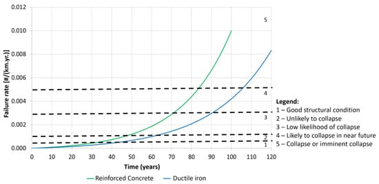
Figure 4.
Deterioration curves and structural condition scale.

Table 1.
Structural condition scale (adapted from [22,26]).
Probability of Service Disruption
The probability of service disruption is a measure of system reliability and, in the present case study, is linked to the lack of redundancy. So, the higher the system redundancy is, the lower the probability of service disruption becomes. In the case of parallel pipes, the probability is determined using Equation (7) [27].
where is the the probability of service disruption at time t (-), t is the time (year), n is the number of assets, and is the probability of failure of asset i at time t (-).
The probability of service disruption of a system in a certain year can be determined based on the asset failure rates. When no information is available to fully describe the failure, a Poisson process can be used, which is suitable in these cases [28]. According to the Poisson process, the probability of failure at a given time is given by Equation (8).
where is the probability of failure of asset i at time t (-), is the failure rate (#/(km.year.)), and t is the time interval in which calculation is being performed (year).
For the Poisson process, the failure is understood as the service disruption and the failure rate is constant. So, for the period in analysis, a value is established up to the middle of the useful life and, after that, a growing evolution by levels was adopted. The probability of failure is estimated by using Equation (8) and the corresponding failure rates associated with the structural condition scale of Table 1 are presented in Table 2.

Table 2.
Probability of service disruption [26,29]).
Risk of Pipe Burst
This metric intends to estimate the risk of a burst event in the industrial water main. Although small leaks exist in the water main, in this context, the burst event only refers to the pipe collapse. This is a major concern of the water utility, since a burst will lead to service disruption. Generally, the risk can be determined by the product of the likelihood of occurrence of a given event by the respective dimensions of consequence as in Equation (9) [30].
where R(t) is the risk of pipe burst at time t (-), t is the time (year), P(t) is the likelihood of a burst event at time t (-), and C(t) is the consequence at time t (-).
The previous metric of the probability of service disruption is used as the likelihood of a burst. The water utility experts considered that the most relevant consequences result from service disruption. These consequences are the impacts to the system operation and maintenance, disturbances to users for the service disruption, and disturbances to third parties (e.g., floods and disturbances on traffic and accessibilities). The dimension consequence considered herein is the service disruption to the industrial park, expressed as the percentage of the volume of water needed and not supplied when a burst occurs in the pipe, which is given by Equation (10).
where C(t) is the consequence at time t (-), is the industrial water conveyed at time t (m3/year.), and is the industrial water demand at time t (m3/year.).
The estimation of the consequence of service disruption resulting from a pipe burst requires the analysis of the various combinations of events leading to this type of failure. In some alternatives, the industrial water supply system consists of a single pipe (A0 and A2), whereas, in others, it is composed of two parallel pipes in which the existing one is rehabilitated (A1 and A3 to A6). So, the consequence of a failure in one or in both pipes needs to be analyzed. For that, an event tree is used, which consists of a sequential diagram that aims to identify the various and possible consequences resulting from a certain initial event. Figure 5 shows the event tree used.
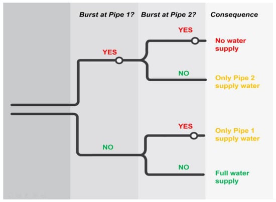
Figure 5.
Event tree used for consequence analysis in alternatives A1 and A3 to A6.
In the case of alternatives A0 and A2, the total risk is computed according to Equation (9), and in the case of alternatives A1 and A3 to A6, it is computed according to Equation (11) [31].
where R(t) is the risk of pipe burst at time t (-), t is the time (year), is the likelihood of a burst event at time t in Pipe 1 (existing pipe) (-), is the likelihood of a burst event at time t in Pipe 2 (new pipe) (-), is the consequence of having no service at time t (-), is the consequence of having only Pipe 1 supplying water at time t (-), is the consequence of having only Pipe 2 supplying water at time t (-), and is the consequence of having full service at time t (-).
For a better perception of the magnitude of risk, a probability–consequence chart is used, as depicted in Figure 6. The acceptance and tolerance level curves are defined, with one corresponding to the boundary between the low and moderate risks (R1) and the other between moderate and high risks (R2). So, it is assumed that R1 = 1 and R2 = 8 based on the reinforced concrete’s useful life determined by Equation (12).
where R1 is the threshold of acceptable risk (-), R2 is the threshold of tolerable risk (-), and u is the useful life of pipe material (years).
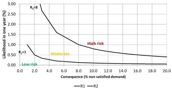
Figure 6.
Thresholds between risk levels.
Operation and Maintenance Costs
This metric quantifies the variable part of O&M costs by summing the water loss production costs and maintenance costs associated with repairing the pipes. The fixed part of these costs is not considered, as this is the same in all alternatives. The O&M costs are calculated by Equation (13) [32].
where is the variable part of operation and maintenance costs (EUR), m is the period of analysis (years), Cp,j is the water lost production costs at time j (EUR/year), is the maintenance costs associated with repairing the pipes at time j (EUR/year), and i is the discount rate (-).
The water lost production costs result from the sum of the annual water acquisition cost from other utilities and the annual treatment cost related to the volume of water lost. The utility needs to buy water from another utility whenever consumption is higher than 25 × 106 m3/year. However, the contract with that other utility establishes that, independently of water consumption, the utility has to always pay a minimum volume of 10 × 106 m3/year. The water acquisition cost includes the real water losses in the system. All water that enters into the system is treated and, therefore, has additional costs that should be considered. The unit treatment cost is about 0.15 EUR/m3. A constant prices analysis is carried out for the evolution of costs over time. The maintenance costs associated with repairing the pipes considered for each alternative correspond to about 1%/year of the capital costs.
Capital Costs
The capital costs include the costs associated to the building of pipes and storage tanks. These costs of pipes are calculated by the product between the unit installation costs that depend on the material, diameter and pressure class, and the respective pipe length [33]. The capital costs of storage tanks result from the product between the unit cost of tank capacity and the capacity to be installed [33]. Whenever investments are not made at the beginning of the period of analysis or in the same year, they should be updated to a reference year (i.e., year 0). The interest rate used to update the costs is 6%. The capital costs are obtained through Equation (14) [32].
where is the capital cost (EUR), m is the period of analysis (years), is the unit cost of pipe installation (EUR/m), L is the pipe length (m), is the unit cost of tank capacity (EUR/m3), is the tan k capacity to be installed (m3), and i is the discount rate (-).
2.5.3. Selection of the Aggregation Method
Several aggregation techniques can be applied such as the additive model, ELECTRE III, MAUT/MAVT, and AHP. Two aggregation methods were chosen in this study—the additive model (also known as weighted sum model or simple additive weighting) and the ELECTRE III—with the aim to compare and discuss the results obtained by each method.
The Additive Model
The additive model is the oldest, the simplest, and the most widely known and used model [34], as described by Equation (15) [35].
where is the global value of the alternative Ai, is the parameter related to inter-criteria evaluation of metric j (also known as weight), is the value of consequence of metric j, and is the outcome of alternative i for metric j.
The additive model requires a normalization procedure of the metrics that consists of carrying out a scale transformation to change all metrics to the same scale, which may change the properties of the original scale (e.g., may change the unity or the origin of the scale) [35]. Typically, the normalization is made to a scale of 0 to 1, in which the least preferred value of consequence () is 0 and the most preferred value of consequence () is 1. However, a different normalization procedure is adopted in this paper.
The normalization procedure considers a scale of 0 to 3, where 0 corresponds to the least preferred value of consequence () of the metric and 3 corresponds to the most preferred value of consequence (). This scale is not linear, but trilinear, with the thresholds defined by the water utility experts according to some references provided by the national sector regulator. The scale can be associated with a traffic light color scheme. The assessment classes defined for each metric are presented in Table 3.

Table 3.
Assessment classes defined for each metric.
The metrics do not have all the same importance and, therefore, different weights may be assigned. These weights need to be normalized to a scale of 0 to 1, considering the condition given by Equation (16) [35].
Obtained results of the application of the referred multicriteria decision analysis (MCDA) are presented and discussed in Section 3.
ELECTRE III
ELECTRE (ELimination et Choix Traduisant la RÉalité) methods are a family of MCDA techniques developed in France. Since their development, which started in the 1960s, ELECTRE methods have been widely used in many real-world decision problems (e.g., energy, transportation, environmental, and water management) and have proved to be suitable for situations where at least five decision criteria are involved [36]. The main advantage of these methods is the possibility of evaluating actions (or alternatives) using ordinal scales (similar or different) for assessing different criteria and not having to normalize results. The ELECTRE family includes several methods distinguished by the type of problematic involved, such as choice, ranking, or sorting, and the ELECTRE III is suitable for the ranking problematic.
ELECTRE methods involve two phases: the construction of one or several outranking relations followed by an exploitation procedure [36,37,38]. The concept of outranking relations was created due to the difficulties encountered with several real problems and is the basis of the so-called French or European school of MCDA [39,40]. The outranking relation is built through the following steps [37,39,41]: (i) computation of the partial concordance indices cj(a,b) and cj(b,a), (ii) computation of the overall concordance indices c(a,b), (iii) computation of the partial discordance indices dj(a,b) and dj(b,a), (iv) computation of the fuzzy outranking relation grounded on the credibility indices σ(a,b), and (v) determination of a λ-cut of the fuzzy relation in order to obtain a crisp outranking relation.
Weights
The weights were assigned by a panel of five experts from the water utility. These weights are assigned on a scale of 1 to 10, in which 10 represents the highest importance level. The five experts debated the importance of each metric and assigned a single value to each metric. Table 4 presents the weights assigned to different metrics and the respective preference direction, whether it is minimizing (↓) or maximizing (↑).

Table 4.
Weights assigned to each metric by a panel of experts from the utility.
2.5.4. Application of the Aggregation Methods and Elaboration of Final Recommendations
The elaboration of final recommendations was produced based on the results obtained with the application of the aggregation methods and the sensitivity and robustness analysis, and these two steps are presented in the Section 3.
3. Results
3.1. Outcomes of Each Assessment Metric
3.1.1. Hydraulic Capacity Adequacy
Figure 7 shows the results obtained for the metric of hydraulic capacity adequacy. The results show that all alternatives considering Scenario 1 showed a lower hydraulic capacity than those obtained for Scenario 2, since the former corresponds to an increase of the expected demand over time and, consequently, a reduction of the transport capacity. Alternative A0 will have insufficient hydraulic capacity adequacy for Scenario 1 and excess for Scenario 2, both of which are after the year 2030. Alternative A2 presents good hydraulic capacity adequacy, being the only predesigned for the water demand foreseen for Scenario 1. Alternatives A1, A3, A4, A5, and A6 are equivalent, showing a small surplus of hydraulic capacity adequacy for Scenario 1 and a larger surplus for Scenario 2.
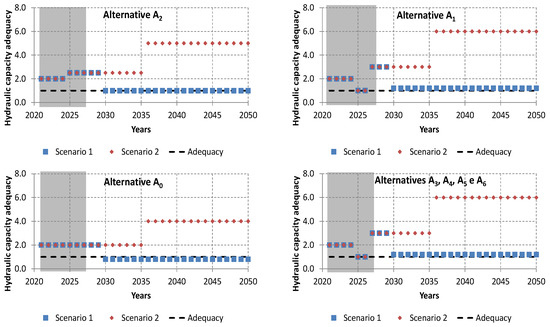
Figure 7.
Results obtained for the hydraulic capacity adequacy.
3.1.2. System Storage Capacity
The results obtained for this metric are depicted in Figure 8. The system storage capacity is always higher in Scenario 1 than in Scenario 2, as expected, since in the first scenario demand increases, and in the second it decreases. The system storage capacity for Alternative A0 in Scenario 1 is always lower than 1 day after 2030. Alternatives A0, A1, and A2 are equivalent in terms of this metric, since they maintain the existing system storage capacity of 50,000 m3. Alternatives A3 and A5 are equivalent as both consider an increase of system storage capacity from 50,000 to 75,000 m3, as well as Alternatives A4 and A6, which consider an increase from 50,000 to 55,000 m3.
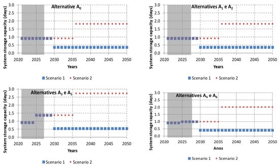
Figure 8.
Results obtained for the system storage capacity.
3.1.3. Infrastructure Value Index
Figure 9 shows the results obtained for the metric of hydraulic capacity adequacy. This metric does not vary with the scenarios. Alternative A0 presents the worst values along the analysis period, which is expected since it corresponds to maintaining the current O&M practices, which are insufficient to improve pipe conditions. Alternative A2 presents the best values in the 20 years, since it corresponds to building a new pipe in 2025 and deactivating the existing one. Alternatives A1, A3, A4, A5, and A6 are quite equivalent, presenting minor differences in their values of the IVI due to the different extension of the new pipe.
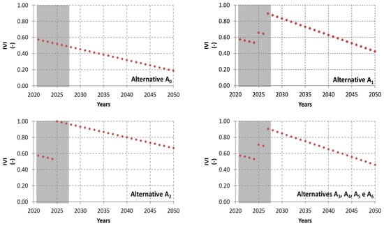
Figure 9.
Results obtained for the infrastructure value index.
3.1.4. Real Water Losses
Figure 10 shows the results obtained for the metric of real water losses. Real water losses are determined using Equation (5) the first year: the volume of water losses in 2021 (i.e., 0.43 × 10⁶ m3/year) is about 4.3% of the total water volume treated annually, which is 115% higher than the water utility experts’ perceptions of 2%. This metric is independent of Scenarios 1 and 2, since the real losses only depend on pipe condition and the pipe deterioration rate. It is assumed that water losses increase over time at a constant rate (according to Equation (5)) and depend on the number of pipes in parallel, the pipe length, and the pipe age (directly related to the pipe condition).
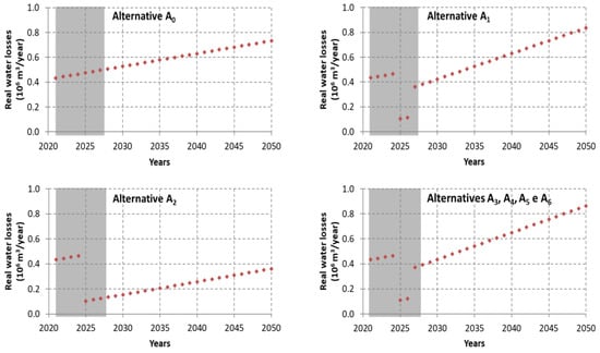
Figure 10.
Results obtained for the real water losses.
Alternative A1 presents slightly higher water losses in 2050 than Alternative A1, meaning that the two pipes of Alternative A1 will have more water losses than the single pipe of Alternative A0. Alternative A2 is the one with less real water losses, since it is composed of a single new pipe, while the others have either a single deteriorated pipe (A0) or two pipes installed in parallel (one new and one rehabilitated).
3.1.5. Structural Condition
The results obtained for the metric of structural condition are presented in Figure 11. Alternative A0 presents an increase of the structural condition index over time from 2 (unlikely to collapse) to 3 (low likelihood of collapse), highlighting a clear degradation over time. Alternatives A1, A3, A4, A5, and A6 present similar structural condition indices, since they involve identical interventions allowing them to improve their global structural condition. This metric only allows for distinguishing alternatives A0 and A2.


Figure 11.
Results obtained for the structural condition.
3.1.6. Probability of Service Disruption
The results obtained for the probability of service disruption are shown in Figure 12. Alternative A0 presents the highest probability of service disruption due to its lack of water supply redundancy and to its present and future condition that cannot be improved only by maintaining current O&M practices. Despite the lack of water supply redundancy, Alternative A2 shows the lowest probability of service disruption due to its better condition. Alternatives A3 and A4 are equivalent, as well as alternatives A5 and A6, with low probability of service disruption values, which are lower than those obtained for A0 and A2.
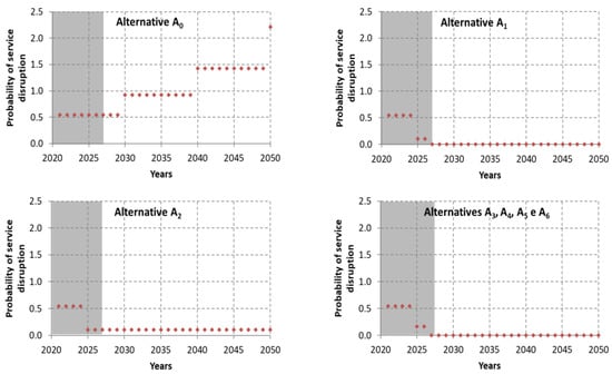
Figure 12.
Results obtained for the probability of service disruption.
3.1.7. Risk of Pipe Burst
Figure 13 present the results obtained for the risk of pipe burst. The risk of pipe burst obtained for Scenario 1 is always higher than that for Scenario 2, since the consequence is a function of water demand, which increases with the increase of water demand. Hence, the risk of pipe burst is clearly scenario dependent. Alternative A0 presents the highest risk of pipe burst, since it corresponds to maintaining the old non-rehabilitated pipe. Alternatives A1, A3, A4, A5, and A6 differ from each other only because of the pipe length. The differences of risk between Alternatives A3 and A4 (equivalent) and Alternatives A5 and A6 (also equivalent) are less than 15%.
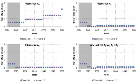
Figure 13.
Results obtained for the risk of pipe burst.
3.1.8. Operation and Maintenance Costs
The results obtained for this metric are presented in Figure 14. Alternative A2 has the lowest O&M costs due to this alternative corresponding to a single pipe from 2025 onwards, which implies a lower volume of water losses and lower maintenance costs. Alternatives A3, A4, A5, and A6 are quite equivalent in terms of O&M costs, with the difference between the cheapest (A6) and the most expensive (A3) ca. 11%.
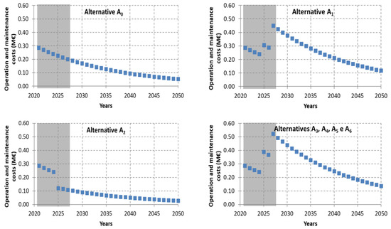
Figure 14.
Results obtained for the operation and maintenance costs.
3.1.9. Capital Costs
The results obtained for the capital costs are presented in Figure 15. Alternative A0 does not have any capital cost since it corresponds to the status quo situation. Alternative A2 presents the lowest capital cost since it involves only the construction of a single pipe. The remaining alternatives differ in costs due to the differences in the new pipe length and in the storage tank capacity.

Figure 15.
Results obtained for the capital costs.
3.2. Application of the Aggregation Method and Sensitivity and Robustness Analysis
3.2.1. Additive Model
The additive model described by Equation (14) is applied to aggregate the previously referred metrics with the weights listed in Table 4. In Figure 16, the evolution of the final score obtained for each alternative overtime for the two scenarios is shown. Obtained results are depicted in Figure 17. In both Scenarios 1 and 2, the best alternative is always A2 and the worst is A0. Alternative A5 is the second best until 2030 for Scenario 1 and from 2040 onwards for Scenario 2. In Scenario 1, from the year 2030 onwards, the ranking of the alternatives is maintained. In Scenario 2, only alternatives A2, A4, and A0 maintain the obtained ranking, whereas the others vary over time for each alternative in both scenarios along the periods of analysis.

Figure 16.
Evolution of the final score obtained for each alternative overtime for the two scenarios.

Figure 17.
Ranking order for each alternative in both scenarios along the periods of analysis.
A sensitivity and robustness analysis was carried out considering different hypotheses, namely, equal weights for all metrics, removal of specific metrics, and the sum of both costs’ metrics. The obtained results show that, in most cases, the best and worst alternatives do not change (i.e., A2 and A0, respectively), but the other alternatives have some position change. When excluding the metrics from the risk dimension (i.e., structural condition, probability of service disruption, and risk of pipe burst), the best alternative is A0 until 2040 and after that the best changes to A2 in Scenario 1, although, in Scenario 2, the best alternative is always A0.
3.2.2. ELECTRE III
The ELECTRE III method uses a pseudo-criteria model, which means that this method allows for incorporating the uncertainty and ambiguity of judgments using discrimination thresholds (i.e., preference and indifference thresholds). Since these discrimination thresholds are difficult to define for non-specialists, like, water utility experts, it was decided not to use them in this case study. The results obtained by applying the ELECTRE III method are shown in Figure 18. In Scenario 1, the best alternative is A1 until 2030, and after that, the best is always A2 due to the increase in expected water demand. In Scenario 2, the best alternative is always A1 independent of the year of analysis. In both scenarios, Alternatives A5 and A6 are equivalent as well as Alternatives A3 and A4. The worst alternative is always A0 for Scenario 1 and Alternatives A5 and A6 in ex-quo for Scenario 2.

Figure 18.
Ranking for each alternative in both scenarios for different periods of analysis.
Similarly to the additive model, a sensitivity and robustness analysis was carried to the ELECTRE model, and the obtained results show that the final rank maintains in both scenarios.
4. Conclusions and Further Research
The obtained results are in line with the utility experts’ expectations. In most carried out analyses, the best solution is Alternative A2, because it consists of building a new pipe and deactivating the existing pipe, which will reduce the risk of pipe failure and O&M costs and will improve the performance of most of the metrics. On the contrary, the worst alternative is always A0, which corresponds to the status quo situation, which is already unsatisfactory, and any of the other alternatives will improve pipe performance in some way. However, the obtained results by both aggregation methods (the additive model and the ELECTRE III) are quite sensitive to the assigned weights and, therefore, other techniques to determine the weights of the metrics should be explored, such as the Simos method. The whole MCDA methodology helped to clarify and support the decision despite being more laborious than other methodologies (e.g., cost–benefit analysis).
In terms of future research, the inter-metric dependency should be further explored aiming at inferring its impact on the final decision. For example, in the present case study, the metric of risk pipe burst uses the metric of the probability of service disruption as the likelihood, which may bias the analysis. Additionally, none of the MCDA techniques developed so far deal with multiple scenarios in decision problems of urban water rehabilitation interventions nor with the time dimension. Thus, future research should address the development of a multicriteria aggregation technique with the possibility to consider several scenarios and the time dimension.
Author Contributions
Conceptualization, N.C., D.C. and M.d.C.A.; methodology, N.C., D.C. and M.d.C.A.; writing—original draft preparation, N.C.; writing—review and editing, D.C. and M.d.C.A.; supervision, D.C. and M.d.C.A.; project administration, N.C.; funding acquisition, N.C. All authors have read and agreed to the published version of the manuscript.
Funding
This research was funded by Fundação para a Ciência e a Tecnologia (FCT) through the WISDom project, grant number no. DSAIPA/DS/0089/2018. The APC was funded by FCT through the WISDom project and by the Polytechnic Institute of Setúbal.
Institutional Review Board Statement
Not applicable.
Informed Consent Statement
Not applicable.
Data Availability Statement
The data presented in this study are available on request from the corresponding author.
Acknowledgments
The authors would like to thank the FCT for funding this research through the WISDom project (grant number DSAIPA/DS/0089/2018) and the water utility for providing data from the case study.
Conflicts of Interest
The authors declare no conflict of interest. The funders had no role in the design of the study; in the collection, analyses, or interpretation of data; in the writing of the manuscript, or in the decision to publish the results.
References
- Carriço, N.; Covas, D.; Almeida, M.d.C. Multi-Criteria Decision Analysis in Urban Water Asset Management. Urban Water J. 2021, 18, 558–569. [Google Scholar] [CrossRef]
- Carriço, N.J.G.; Covas, D.I.C.; Almeida, M.C.; Leitão, J.P.; Alegre, H. Prioritization of Rehabilitation Interventions for Urban Water Assets Using Multiple Criteria Decision-Aid. Water Sci. Technol. 2012, 66, 1007–1014. [Google Scholar] [CrossRef]
- Cardoso, M.A.; Poças, A.; Silva, M.S.; Ribeiro, R.; Almeida, M.C.; Brito, R.S.; Coelho, S.T.; Alegre, H. Innovation Results of IAM Planning in Urban Water Services. Water Sci. Technol. 2016, 74, 1518–1526. [Google Scholar] [CrossRef][Green Version]
- Cardoso, M.A.; Brito, R.; Ribeiro, R.; Alegre, H. Infrastructure Asset Management—Maturity Assessment of Water Utilities Based on International Standards ISO 55000. In Proceedings of the LESAM 2017—Leading Edge Conference for Strategic Asset Management, Trondheim, Norway, 20–22 June 2017. [Google Scholar]
- Alegre, H.; Almeida, M.C.; Covas, D.I.C.; Cardoso, M.A.; Coelho, S.T. Integrated Approach for Infrastructure Asset Management of Urban Water Systems. In Proceedings of the LESAM 2011–Leading Edge Conference for Strategic Asset Management, Mülheim an der Ruhr, Germany, 27–30 September 2011. [Google Scholar]
- Rogers, C.D.F.; Hao, T.; Costello, S.B.; Burrow, M.P.N.; Metje, N.; Chapman, D.N.; Parker, J.; Armitage, R.J.; Anspach, J.H.; Muggleton, J.M.; et al. Condition Assessment of the Surface and Buried Infrastructure—A Proposal for Integration. Tunn. Undergr. Space Technol. 2012, 28, 202–211. [Google Scholar] [CrossRef]
- AWWA. Condition Assessment of Water Mains—Manual M77; American Water Works Association: Denver, CO, USA, 2019; ISBN 978-1-61300-503-3. [Google Scholar]
- St. Clair, A.M.; Sinha, S. State-of-the-Technology Review on Water Pipe Condition, Deterioration and Failure Rate Prediction Models! Urban Water J. 2012, 9, 85–112. [Google Scholar] [CrossRef]
- Liu, Z.; Kleiner, Y. State of the Art Review of Inspection Technologies for Condition Assessment of Water Pipes. Measurement 2013, 46, 1–15. [Google Scholar] [CrossRef]
- Dawood, T.; Elwakil, E.; Novoa, H.M.; Delgado, J.F.G. Artificial Intelligence for the Modeling of Water Pipes Deterioration Mechanisms. Autom. Constr. 2020, 120, 103398. [Google Scholar] [CrossRef]
- Fitchett, J.C.; Karadimitriou, K.; West, Z.; Hughes, D.M. Machine Learning for Pipe Condition Assessments. J. Am. Water Work. Assoc. 2020, 112, 50–55. [Google Scholar] [CrossRef]
- Scholten, L.; Scheidegger, A.; Reichert, P.; Mauer, M.; Lienert, J. Strategic Rehabilitation Planning of Piped Water Networks Using Multi-Criteria Decision Analysis. Water Res. 2014, 49, 124–143. [Google Scholar] [CrossRef] [PubMed]
- Bouyssou, D.; Marchant, T.; Pirlot, M.; Tsoukiàs, A.; Vincke, P. Evaluation and Decision Models with Multiple Criteria: Stepping Stones for the Analyst; Springer Science + Business Media, Inc.: Boston, MA, USA, 2006; ISBN 978-0-387-31098-5. [Google Scholar]
- Alegre, H.; Vitorino, D.; Coelho, S. Infrastructure Value Index: A Powerful Modelling Tool for Combined Long-Term Planning of Linear and Vertical Assets; Elsevier Ltd.: Amsterdam, The Netherlands, 2014; Volume 89, pp. 1428–1436. [Google Scholar]
- Amaral, R.; Alegre, H.; Matos, J.S. A Service-Oriented Approach to Assessing the Infrastructure Value Index. Water Sci. Technol. 2016, 74, 542–548. [Google Scholar] [CrossRef] [PubMed][Green Version]
- Cabral, M.; Loureiro, D.; Covas, D. Using Economic Asset Valuation to Meet Rehabilitation Priority Needs in the Water Sector. Urban Water J. 2019, 16, 205–214. [Google Scholar] [CrossRef]
- Lai, C.-D.; Xie, M. (Eds.) Mean Residual Life—Concepts and Applications in Reliability Analysis. In Stochastic Ageing and Dependence for Reliability; Springer: New York, NY, USA, 2006; pp. 109–138. ISBN 978-0-387-34232-0. [Google Scholar]
- Laven, K.; Lambert, A.O. What Do We Know about Real Losses on Transmission Mains? In Proceedings of the IWA Water Loss Conference, Manila, Philippines, 22–25 January 2012. [Google Scholar]
- Rajani, B.; Kleiner, Y. Comprehensive Review of Structural Deterioration of Water Mains: Physically Based Models. Urban Water 2001, 3, 151–164. [Google Scholar] [CrossRef]
- Kleiner, Y.; Rajani, B. Water Main Assets: From Deterioration to Renewal. In Proceedings of the AWWA Annual Conference, Anaheim, CA, USA, 15–19 June 2003; pp. 1–12. [Google Scholar]
- IPWEA; NAMS. Condition Assessment and Asset Performance Guidelines; IPWEA: Sydney, Australia, 2012; p. 26. [Google Scholar]
- WRc. Sewerage Rehabiltation Manual, 4th ed.; Water Research Centre: Wiltshire, UK, 2001. [Google Scholar]
- IPWEA; NAMS. International Infrastructure Management Manual, 5th ed.; IPWEA: Sydney, Australia; NAMS Group: Wellington, New Zealand, 2015; ISBN 978-0-473-10685-0. [Google Scholar]
- Liu, Z.; Kleiner, Y.; Rajani, B. Condition Assessment Technologies for Water Transmission and Distribution Systems; U.S. Environmental Protection Agency (EPA): Cincinnati, OH, USA, 2012.
- Shamir, U.; Howard, C.D.D. An Analytic Approach to Scheduling Pipe Replacement. J. AWWA 1979, 71, 248–258. [Google Scholar] [CrossRef]
- Al-Barqawi, H.; Zayed, T. Condition Rating Model for Underground Infrastructure Sustainable Water Mains. J. Perform. Constr. Facil. 2006, 20, 126–135. [Google Scholar] [CrossRef]
- Assis, R. Apoio à Decisão Em Manutenção Na Gestão de Activos Físicos; Lidel—edições técnicas, Lda.: Lisboa, Portugal, 2010; ISBN 978-972-757-605-0. [Google Scholar]
- Almeida, A.B. Incertezas e Riscos: Conceptualização Operacional; Água, Ciência e Sociedade; APRH, Ed.; Esfera do Caos: Lisboa, Portugal, 2011; ISBN 978-989-680-044-4. [Google Scholar]
- ERSAR. Water and Waste Services Quality Assessment Guide: 2nd Generation of the Assessment System; ERSAR: Lisbon, Portugal, 2017; ISBN 978-989-8360-11-. [Google Scholar]
- Aven, T. What is a Risk Analysis? In Risk Analysis; John Wiley & Sons, Ltd.: Hoboken, NJ, USA, 2008; pp. 3–15. ISBN 978-0-470-69443-5. [Google Scholar]
- Aven, T.; Kørte, J. On the Use of Risk and Decision Analysis to Support Decision-Making. Reliab. Eng. Syst. Saf. 2003, 79, 289–299. [Google Scholar] [CrossRef]
- Mays, L.W. Urban Water Supply Handbook; McGraw-Hill Education: New York, NY, USA, 2002; ISBN 978-0-07-137160-5. [Google Scholar]
- Marchionni, V.; Cabral, M.; Amado, C.; Covas, D. Estimating Water Supply Infrastructure Cost Using Regression Techniques. J. Water Resour. Plan. Manag. 2016, 142, 04016003. [Google Scholar] [CrossRef]
- Podvezko, V. The Comparative Analysis of MCDA Methods SAW and COPRAS. Eng. Econ. 2011, 22, 134–146. [Google Scholar] [CrossRef]
- de Almeida, A.T.; Cavalcante, C.A.V.; Alencar, M.H.; Ferreira, R.J.P.; de Almeida-Filho, A.T.; Garcez, T.V. Multicriteria and Multiobjective Models for Risk, Reliability and Maintenance Decision Analysis, 1st ed.; Zhu, J., Ed.; Springer International Publishing: Cham, Switzerland, 2015; Volume 231, ISBN 978-3-319-17968-1. [Google Scholar]
- Figueira, J.; Greco, S.; Roy, B.; Slowinski, R.; Pardalos, P.M.; Hearn, D. ELECTRE Methods: Main Features and Recent Developments. In Handbook of Multicriteria Analysis; Zopounidis, C., Pardalos, P.M., Eds.; Springer: Berlin/Heidelberg, Germany, 2010; pp. 51–89. ISBN 978-3-540-92828-7. [Google Scholar]
- Almeida-Dias, J.; Figueira, J.R.; Roy, B. The Software ELECTRE III-IV: Methodology and User Manual (Version 3.x); Lamsade-Universite Paris Dauphine: Paris, France, 2006. [Google Scholar]
- Figueira, J.; Mousseau, V.; Roy, B.; Hillier, F.S. Electre Methods. In Multiple Criteria Decision Analysis: State of the Art Surveys; Figueira, J., Greco, S., Ehrgott, M., Eds.; Springer Science + Business Media, Inc.: Berlin/Heidelberg, Germany, 2005; pp. 133–153. ISBN 0-387-23067-X. [Google Scholar]
- Roy, B. The Outranking Approach and the Foundations of Electre Methods. Theory Decis. 1991, 31, 49–73. [Google Scholar] [CrossRef]
- Roy, B.; Vanderpooten, D. The European School of MCDA: Emergence, Basic Features and Current Works. J. Multi-Criteria Decis. Anal. 1996, 99, 22–38. [Google Scholar] [CrossRef]
- Rogers, M.; Bruen, M. Using ELECTRE III to Choose Route for Dublin Port Motorway. J. Transp. Eng. 2000, 126, 313–323. [Google Scholar] [CrossRef]
Publisher’s Note: MDPI stays neutral with regard to jurisdictional claims in published maps and institutional affiliations. |
© 2021 by the authors. Licensee MDPI, Basel, Switzerland. This article is an open access article distributed under the terms and conditions of the Creative Commons Attribution (CC BY) license (https://creativecommons.org/licenses/by/4.0/).