Abstract
Vortex drop shafts are special manholes designed to link sewer channels at different elevations. Significant energy head dissipation occurs across these structures, mainly due to vertical shaft wall friction and turbulence in the dissipation chamber at the toe of the shaft. In the present study two aspects, sometimes neglected in the standard hydraulic design, are considered, namely the energy head dissipation efficiency and the maximum pressure force in the dissipation chamber. Different physical model results derived from the pertinent literature are analyzed. It is demonstrated that the energy head dissipation efficiency is mostly related to the flow impact and turbulence occurring in the chamber. Similarly to the drop manholes, a relation derived from a simple theoretical model is proposed for the estimation of the energy head loss coefficient. The analysis of the pressures measured on the chamber bottom allows to provide a useful equation to estimate the pressure peak in the chamber as a function of the approach flow energy head.
1. Introduction
The recourse to sewer drop structures to convey water discharges from an upper elevation to a lower one has been well known for more than 30 years [1,2,3]. Two basic drop structures were originally conceived: vortex drop shafts [4] and plunging drop structures [5]. The main difference between the two consists in the flow behaviour at the top of the shaft. In plunging drop structures the incoming flow is issued from the inlet channel to the vertical shaft without any control. In vortex drop shafts a swirling motion is, instead, imposed to the approach flow by a specific inlet device placed above the shaft. Over the following years different drop structure layouts have been proposed [6,7,8,9,10]. The research on the optimization of the flow behaviour in such structures is still in progress, being motivated by the urgent necessity to carry rainwater discharges in deep tunnels and storage basins to prevent urban floods [11].
Vortex drop shafts are composed of three main components: (1) the inlet structure, which consists, in turn, of an inlet channel and an inlet device, (2) the vertical shaft and (3) the outlet structure with a dissipation chamber and an outlet tunnel. The inlet structure conveys the approach flow through a sloped free-surface inlet channel, and it generates the swirl flow. Mulligan et al. [12] recapitulated the different configurations of the inlet device as proposed in the technical literature. All of them, anyway, transfer an angular momentum to the approach flow which is forced to adhere to the outer wall and spiral downward along the shaft [13]. Here, a two-phase flow establishes: the water clings to the shaft walls and it dissipates energy due to the shaft friction, whereas an air core forms at the shaft center. The flow, then, falls in the dissipation chamber as a vertical annular free-jet [14]. The chamber de-aerates this incoming mixture of water and air and it transforms the vertical motion into a horizontal flow which enters the outlet tunnel. A further energy head dissipation due to the impact of the free-jet on the chamber bottom occurs. The flow behaviour in the chamber can be still improved by installing specific appurtenances, such as baffles, weirs, venturi or sumps [2,15], aiming to dissipate more energy, calm the flow and reduce the pressure on the bottom thanks to the formation of a water cushion.
The design of vortex drop shafts is currently based on guidelines derived by several experimental studies. The recommendations related to the inlet structure strictly depend on the energy content of the approach flow. The flow characteristics in supercritical inlet devices were described in detail by [3,16,17]. If the approach flow is, instead, subcritical, then it is possible to follow the indications of [18]. The diameter of the vertical shaft can be easily calculated by applying the empirical relations of [3,19,20]. The standard dimensions of the dissipation chamber were provided by [14]. Few recommendations are, contrarily, available regarding the total energy head dissipation and the pressure forces straining the different components of the vortex drop shaft, despite their fundamental role in the hydraulic operation of the structure during its lifetime.
Past experimental studies [4,21] ascertained that the energy head dissipation of vortex drop shafts with Ls/Ds larger than 50.0 (Ls and Ds are the shaft length and diameter, respectively) is almost 90%. Zhao et al. [20] and Mahmoudi-Rad and Khanjani [22] demonstrated that energy head dissipation of 90% can also be reached for shafts of relatively small length Ls between 10.0∙Ds and 16.0∙Ds when a water cushion is formed below the shaft outlet. For even shorter shafts, flow dissipation decreased down to about 70% [7,23]. The flow pressure distribution was investigated by [20,24], who presented detailed shaft wall pressure measurements. Wall pressure peaks along the highest part of the shaft were shown to be mainly caused by the centrifugal forces. Zhao et al. [20] also showed that a 1-D model based on the assumptions of free vortex and circularly uniform flow led to a significant underestimation of the wall pressure forces. A recent physical and numerical study on the wall pressure was conducted by [24]. They demonstrated that the maximum pressure was registered in the first part of the shaft, where the centrifugal forces are still preponderant. Pressure fluctuations between negative and positive values were detected, with a positive average value.
This literature review highlights that some gaps should still be filled to advance the knowledge about vortex drop shafts. Few design recommendations are available to predict the energy head dissipation in new vortex drop shafts to be realized. Some guidelines would be also desirable to select the component materials with an adequate resistance to face the pressure peaks. The present study aims to provide a valuable contribute under this design perspective. Some experimental data derived by past investigations on physical devices of vortex drop shafts are retained, and the results are used to provide useful guidance for engineers involved in the design or the hydraulic rehabilitation of vortex drop shafts.
2. Materials and Methods
2.1. Physical Device Layout
The elaborations described in this paper are based on different experimental data [8,15,17,22,25,26]. All of them were collected by performing experiments in physical devices of vortex drop shafts in compliance with the standard layout of Figure 1. According to this scheme a rectangular inlet channel (subscript o) of width b conveys the approach flow in the inlet device. The approach flow was supercritical (Fo = Vo/(g∙ho)0.5 > 1.00, with g as the gravity acceleration and Vo and ho as the approach flow average velocity and depth, respectively, except for [15,25]. The inlet device consists in a tangential inlet or in a spiral inlet device, in which the approach flow is abruptly deviated towards the shaft and it assumes the typical helicoidal flow with a stable air core. Then, the flow falls down by clinging on the vertical shaft wall. The shaft presents a relative length Ls/Ds ranging between 4.55 [26] and 23.52 [8]. According to the classification used by [20] both short and relatively long vertical shafts are retained. In all the experimental set-ups, a dissipation chamber with a height Lch and a length Sch is placed at the toe of the shaft. The chamber is always equipped with one or more air venting pipes to de-aerate the flow. In addition, the physical device of [22] was characterized by the possibility to add a sump and a baffle in the chamber, with the aim to mitigate the flow impact onto the chamber bottom and to increase the energy head dissipation. In the end, an outlet tunnel (subscript u), with a circular or rectangular cross-section of diameter Du or width bu, respectively, exits the dissipation chamber.
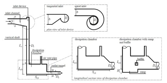
Figure 1.
Geometry of vortex drop shafts with detail of tangential and spiral inlets and the dissipation chamber. Note that the represented sketch reports a circular outlet tunnel.
2.2. Instrumentation
A large set of measurements were collected during the experiments of [8,15,17,22,25,26]. Among all, the elaborations of the present study focus basically on the experimental measurements of:
- the approach discharge Q entering the vortex drop shaft structure
- the flow depths h along the inlet channel and the outlet tunnel
- the pressures p registered on the bottom of the dissipation chamber
Q was measured through inductive discharge devices [8,17], with a ±0.5% full scale (FS) accuracy, and with electromagnetic flowmeters of ±0.5% FS accuracy [22,26]. Del Giudice et al. [15] used a differential pressure discharge-meter with an accuracy of ± 0.1%. As in the standard physical model investigations on hydraulics, h was measured by using point gauges. In addition, ultrasonic level probes were adopted in [26]. The maximum reading error of both the point gauges and the ultrasonic probes was equal to ±0.5 mm. The pressures at the bottom of the dissipation chamber were measured by [17,26]. These investigations shared the same pressure measurement apparatus, consisting in piezometers along the chamber axis, with a maximum reading error of 1 mm of water column. In [17] six piezometers were located at x/Sch = 0.01, 0.12, 0.24, 0.48, 0.72 and 0.96, being x the streamwise coordinate with origin at the backwall of the dissipation chamber. Five piezometers were, instead, placed at roughly x/Sch = 0.12, 0.33, 0.53, 0.74 and 0.94. in [26].
As described, type and modality of experimental measurements in the above-mentioned investigations were quite similar. The instrumentation systems in the various experimental facilities had the same characteristics. The physical measurement principles and methods were equal. In addition, the hydraulic conditions under which the measurements were carried out were the same, as shown in the following Section 2.3. This allows to compare the corresponding results, given that the uncertainty originated from possible systematic errors in the measurement processes can be considered as homogenous among the different studies.
2.3. Experimental Dataset
The main hydraulic and geometric features of the experimental campaigns are described in Table 1. The latter includes the capacity Froude number FC = Q/(g∙Ds5)0.5 to normalize the discharge Q and to compare it among the various investigations. An additional dimensionless discharge Q* = Q/(gDu5)0.5 is also reported because it is useful in the applications described in the Section 3. As shown, [8] performed test-runs under a supercritical flow regime with the largest value of Fo, whereas the largest value of FC was achieved during the experiments of [15,25]. As regards the model geometry, the relative dimensions of the physical devices are quite similar. The size of the dissipation chamber studied by [15,25] stands out compared with the other ones.

Table 1.
Geometrical and hydraulic details of various studies on vortex drop shafts.
3. Results
3.1. Energy Head Dissipation
Energy head dissipation across vortex drop shafts is basically caused by four main phenomena:
- the formation of standing and shock waves due to the perturbance of the approach supercritical flow [27] in the inlet device, and particularly in the spiral as occurred in the present physical devices
- the roughness effect along the vertical shaft
- the impact of the falling flow outing from the vertical shaft onto the bottom of the dissipation chamber
- turbulence in the dissipation chamber, due to which a complex internal flow pattern occurs and the turbulent kinetic energy is rapidly dissipated
The total energy head dissipation is ΔH = Ho − Hu, where Ho is the approach flow energy head in the inlet channel and Hu is the outflow energy head in the outlet tunnel. Free-surface flows were observed along the inlet channel and the outlet tunnel during all the experiments analyzed in this paper. If a horizontal datum corresponding with the chamber invert is assumed, then Ho and Hu are derived from:
where ho and hu are the flow depths along the inlet channel and the outlet tunnel, respectively. They were measured where the flow achieved the uniform flow condition. The energy efficiency ηt is thus defined as ηt = ΔH/Ho. The latter is derived in this study as a function of the measured values of h and V across the sections o-o and u-u (Figure 1).
Otherwise, the energy head dissipation due to the flow passage along the spiral inlet and the vertical shaft only is herein computed as a function of the velocity Vs of the flow outing from the shaft (at the horizontal section s–s as represented in Figure 1). The latter is a function of the axial and tangential velocity components of the swirling flow along the shaft and it can be obtained by following the computational procedure suggested by [17,28]. Consequently, the energy head Hs at the shaft outflow is:
Equation (3) is derived under the simplifying assumption that the flow depth of the outflow from the shaft can be neglected. The flow thickness in the shaft decreases from the inlet device- to the shaft outlet cross-section to values of about 0.5–3.0% of Ds [17,28], therefore this hypothesis does not lead to a significant error. If Equation (3) is applied, then it is possible to derive the energy efficiency ηs limited to the flow along spiral inlet and the vertical shaft as ηs = (Ho− Hs)/Ho.
The energy efficiency η versus Q* is represented in Figure 2 according to the physical model observations of [8]. ηs is almost constant despite the discharge variation, and it ranges between 16.4% and 18.1%. ηt slightly decreases, instead, as Q* increases, and it particularly varies between 94.8% (Q* = 0.87) and 98.6% (Q* = 0.06). This evidence agrees with the physical observations of [5,10,29,30] for different types of drop shafts. Tall drop shafts do not generate a significant variation of the energy head loss by varying Q*. In addition, as an example Figure 2 shows the energy head dissipation distribution for Q* = 0.73. Most of the energy is dissipated in the dissipation chamber, upstream of which H decreases by only 17.2% due to the flow passage along the spiral inlet and the vertical shaft. The main flow mechanism causing the energy head dissipation is the flow impact on the bottom of the dissipation chamber and the turbulence inside this component.
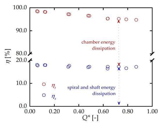
Figure 2.
Energy head dissipation efficiency η versus the dimensionless discharge Q*.
The head loss coefficient K of drop manholes is defined as:
Different studies [30,31,32,33,34] examined K of drop manholes. In these investigations K was correlated to the drop parameter Dr = (gd)0.5/Vo, where d is the drop height. [30] introduced an empirical equation to estimate K for drop manholes, according to which:
No previous studies on vortex drop shafts paid attention to this energy parameter, instead. Vortex drop shafts are, indeed, large drop structures compared to the conventional drop manholes, and the possibility to concentrate all the flow instabilities and local shock waves, pulsations and turbulence, which provoke energy head losses across the entire structure, in a single coefficient appears rather ambitious. However, the computation of K in the preliminary design of a vortex drop shaft might be useful.
According to Equations (1) and (2), K is also:
If d is substituted with the sum of Ls and Lch, then Dr changes in Dv = [g (Ls+Lch)]0.5/Vo and Equation (6) can be rewritten as:
where Dv is the dimensionless vortex drop parameter. Equation (7) shows that K depends essentially on the geometrical characteristics of the vortex drop shaft, mainly concentrated in Dv, and on the dynamic features of the approach and outlet flows, namely the flow velocity and the water depths. If neglecting the term ho − hu, which is close to zero, then Equation (7) becomes:
According to the experimental data collected by [8,22,26], the term Vu2/Vo2 is equal to 0.5, on average. If this approximation is accepted, then K can be estimated as:
Figure 3 shows the variation of K versus Dv. The experimental data corresponding to the investigations of Table 1 are reported in the figure. The datapoints are adequately fitted (R2 = 0.95, with R2 as the correlation coefficient) by the curve of Equation (9). This equation is obviously affected by the measurement uncertainty of the independent variables which is function of. In the present experiments Vo was derived from the measurements of Q and ho. They are the independent variables, therefore. The respective measurement uncertainties should be combined to assess the standard uncertainty of the predicted value of K. According to the mathematical laws of the propagation of the uncertainty, the absolute uncertainty of K is
where ∂Q and ∂ho are the uncertainties in the measurement of Q and ho and a = 2g(Ls+Lch)b is a constant parameter depending basically on the structure geometry. If the errors in the calibration of the instruments and in the data collection are neglected, then the measurement uncertainty can be considered equal to the error derived by the instrumentation accuracy. The latter is detailed in the Section 2.2. As an example, the measurements of ho and Q collected by [8] for approach supercritical flows lead to an upper limit of the error equal to ∂K = ±1.50, which can be safely retained as not preponderant in the calculation of K being only 5% of the corresponding estimated value. The confidence interval of 95% is, therefore, assumed.
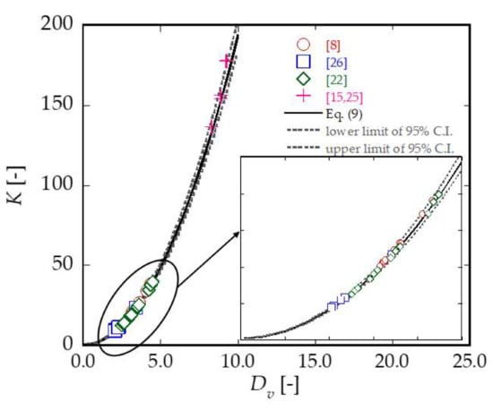
Figure 3.
Measured and predicted values of the local head loss coefficient K and 95% confidence limits as a function of the vortex drop parameter Dv.
To examine the estimation performance of the Equation (9), its uncertainty is evaluated by the confidence interval of the estimation errors. Since the order of the magnitude of K varies significantly by considering both approach sub- and supercritical flows, the estimation error is herein defined as ε = logKest − logKobs, where subscripts est and obs denote the estimated and observed values of K, respectively. Table 2 reports the mean value με and the standard deviation σε of ε along with the errors of 95% confidence interval (C.I.). According to these statistical metrics, if K is predicted by Equation (9), then 95% of the predicted head loss coefficient is in the range between 0.97 and 1.05 times the observed value. Figure 3 also shows the lines of 95% confidence interval. The data for approach supercritical flows [8,22,26] are all within the 95% confidence limits, while a modest scattering is observed for large K corresponding to approach subcritical flows [15,25].
Table 2.
Estimation errors of Equation (9).
Equation (9) is very similar to Equation (5) valid for drop manholes. The same type of equation gives, therefore, satisfactory predictions for both drop manholes and vortex drop shafts. This result was unexpected, because it shows that percentage of velocity head conserved by the flow exiting the manhole is the same one regardless type, dimension and drop mechanism of the drop structure.
As shown in Figure 3, values of K are between 10 and 40 for supercritical vortex drop shafts. If the approach flow entering the vortex drop shaft is, instead, subcritical, as observed by [15,25], then K increases up to 130-160. Conversely, the local head coefficients for drop manholes are smaller than 20 [30,32]. If the terms of Equation (9) are multiplied by the approach flow velocity head, then the energy head loss is computed as [30]:
According to the form of Equation (11) it can be argued that, due to the swirling motion along the vertical shaft and the impact onto the bottom of the dissipation chamber, the flow loses 50% of the approach flow velocity head and, obviously, all the datum head relative to the dissipation chamber base.
The computation of the flow velocity Vs at the shaft outflow through the analytical procedure described by [27,28] allows also to calculate Hs and, then, the shaft head loss coefficient Ks:
where ΔHs = Ho − Hs is the head loss occurred along the spiral inlet and the vertical shaft. The experimental values of Ks derived by the investigations of [8,26] are plotted against Dv in Figure 4. Here, the experiments of [8,26] are considered because the respective physical devices of vortex drop shaft were similar (spiral inlet at the top of the shaft and approach supercritical flow). Figure 4 indicates that Ks is smaller than K, being between about 3 and 20. The coefficients derived by the tests of [26] are larger than for [8], probably because the relative shaft length Ls/Ds of [26] is smaller than the limit depth at which the retarding forces due to the wall friction are balanced by the gravity driving forces [2]. Vs is, therefore, smaller than in the condition where the quasi-uniform flow at the end of the vertical shaft is achieved, as instead observed by [8], and consequently Ks increases.
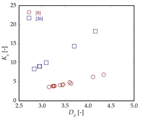
Figure 4.
Variation of the head loss coefficient Ks as a function of the drop parameter Dv for vortex drop shafts.
3.2. Pressure Forces in the Dissipation Chamber
The structural aspects in the design of vortex drop shafts are sometimes dangerously neglected. Even if the existing hydraulic rules and recommendations to be applied for sizing the manhole are respected, the impact of the flow onto the chamber invert accompanied by pressure peaks or frequent pressure fluctuations may cause the collapse of the entire structure. This ruinous scenario can particularly occur in the dissipation chamber. The latter is typically sized to comply with the design guidelines of [14] to avoid the chamber submergence by the air-water mixture flow and, consequently, the pressurization of the outlet tunnel. An additional equipment in the chamber to facilitate further energy head dissipation was proposed by [15,25]. However, the importance of respecting these hydraulic recommendations can be lowered if the pressure forces due to the impact of the falling free-jet on the chamber bottom are not adequately counteracted by the chamber material resistance. The prediction of the maximum pressure is, thus, fundamental to select the optimal manhole material.
The measurements of the pressure on the dissipation chamber invert were recently reported in the experimental studies of [17,26] and they are represented together in Figure 5. The physical device utilized by [17] was the same of [8].
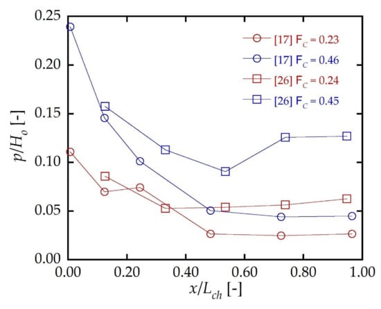
Figure 5.
Maximum relative invert pressure p/Ho as measured along the dissipation chamber axis.
As reported in Figure 5, the pressure distribution along the chamber axis is basically decreasing from the upstream part of the chamber (x/Lch = 0.00) to the downstream (x/Lch = 1.00). The pressure peak is always localized just below the shaft outflow, being clearly provoked by the impact flow on the chamber bottom. This is, thus, the most vulnerable part to structural damage. The minimum pressure is detected downstream, just before the chamber outlet cross-section, as observed by [17] or a little further upstream according to the observation of [26].
Figure 6 shows the relation between FC and the relative maximum invert pressure p/Ho. There is a clear agreement among most of the experimental data. Some 5% to 25% of the approach flow energy head manifests as instantaneous maximum pressures at the chamber invert. It is also evident that p/Ho increases as FC increases too, with a gradient more significant for FC < 0.30. The maximum values of p/Ho in the dissipation chamber are fitted with a good accuracy (R2 = 0.95) by the equation:
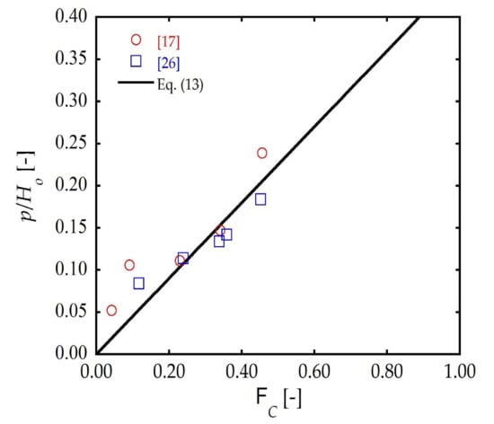
Figure 6.
Maximum relative invert pressure p/Ho against the capacity Froude number FC.
The estimation of p by applying the Equation (13) is affected by the uncertainty in the measurements of ho, Vo and Q. According to the same assumptions made for the Equation (9), the upper limit of the uncertainty of p by Equation (13) is ±0.10 m, as derived from the measurements of [17].
4. Discussion
The Equations (9) and (13) complete, ideally, the set of relations to be employed when a new vortex drop shaft must be designed or when the operation of existing vortex drop shafts need to be verified [35]. For the sake of clarity, their estimation uncertainty should be taken into consideration for engineering applications. As known, the definitional uncertainty is negligible with respect to the other components of measurement uncertainty. The objective of measurement is, then, to establish a probability that this essentially unique value lies within an interval of measured quantity values, based on the information available from measurements [36]. The latter is described, in detail, in the Section 2.2, but what really matters is what goes on the propagation of measuring uncertainties in the results. In particular, the Equation (9) is affected by the uncertainty of Vo. If Vo is directly measured, then the error in the estimation of K depends mainly on the accuracy of the instrument used for measuring Vo. In the present investigations, however, Vo depends on the measurements of Q and ho, whose uncertainties combine themselves by giving a negligible error in the prediction of K by Equation (9). Same consideration is valid for the Equation (13).
In the design phase of vortex drop shafts, the values of the design discharge Qd, the elevation difference Δz between the inlet channel and the outlet tunnel inverts, the geometry of the inlet channel and the outlet tunnel and the uniform flow conditions of the approach flow (ho, Vo, Fo) are typically assigned. A standard computational procedure to achieve a preliminary design of the vortex drop structure is proposed as follows:
- the shaft diameter Ds can be quickly derived as Ds = σ∙(Qd2/g)0.20. The values of the safety coefficient σ∙against the occurrence of the choking condition in the shaft are suggested by [3,19,20].
- As in the investigations considered in the present paper, the inlet device can be standardly chosen between the tangential and the spiral inlet devices. Their geometry parameters are described in detail by [37]. The tangential inlet device has a simpler geometry and it is more compact [16] than the spiral inlet, but it is characterized by an eccentric straight-walled contraction which may provoke undesirable effects as blockages when the rainwater flow carries debris.
- Ref. [14] provided simple equations to define the height Lch, the length Sch and the width Bch of the dissipation chamber as a function of the largest value of either Ds or the outlet tunnel characteristic dimension Du or bu. The three dimensions of the dissipation chamber can be, thus, derived. In the experiments herein considered the chamber geometry agreed with the recommendations of [14], and during the corresponding test-runs the flow behavior in the chamber was acceptable.
- Given the chamber height Lch, the shaft length Ls is calculated as Ls = Δz − Lch.
- The vortex shaft drop parameter is now derived as Dv = [g(Ls+Lch)]0.5/Vo. This allows to compute the total head loss coefficient K through the Equation (9) and, consequently, to obtain the energy head Hu of the flow in the outlet tunnel. According to the present experimental dataset, it was demonstrated that 95% of the predicted head loss coefficients is in the range between 0.97 and 1.05 times the observed value. The error in the estimation of Hu is, thus, negligible.
- The computation of the outflow energy head Hu leads to some considerations about the energetic content in the outlet tunnel. This is a fundamental stage, during which the hydraulic conditions of the flow outing from the dissipation chamber must be compared with the given features of the uniform flow of the existing outlet tunnel. For instance, an excessive head velocity Vu2/2g would implicate the occurrence of abrasion phenomena, possibly intolerable by the existing outlet tunnel conditions [38].
- If the shaft energy head dissipation should be modified to conveniently adjust the value of K, then it is possible to evaluate the addition of some elements, as bend, sump, venturi, baffle or weir in the chamber [15,25] to increase, or decrease, the value of Hu.
- In the end, Equation (13) is available to estimate the maximum pressure p acting on the chamber bottom. This phase is needed to select the chamber material, by comparing the maximum material resistance with p and, if necessary, to consider a specific bottom chamber armor just in correspondence of the shaft outflow in order to prevent scour phenomena. The last aspect is particularly significant also for non-conventional applications, as in a beach drainage system [39]. In such a configuration, the vortex drop shaft can substitute the traditional deep cockpit collecting several drainage pipes: in fact, due to the mixture of seawater with trace of sand, this element is significantly affected by abrasive phenomena.
Finally, as a further application of the outcomes provided by the present study, it is worth to note as the free-surface flows issued by vortex drop shafts have found a novel use in the application of hydroelectric power generation [40,41]. In particular, the present research is also supporting the development of a special turbine architecture based on vortex drop shaft hydrodynamics, which is going to be applied into an innovative overtopping-type wave energy converter [42]. Indeed, when very low-head hydraulic conditions are combined to non-freshwater applications, several problems are observed if traditional hydro turbine are used. This provides a future research direction able to enlarge the relevance of the findings of the present study to other sectors of the fluid mechanics, providing an interesting source of multi-disciplinary innovation.
5. Conclusions
Vortex drop shafts are special sewer drop structures. In the urban drainage practice, they are designated to throw stormwater and sewerage away by addressing them from a shallow sewer channel to a deep tunnel. The flow phenomena typically occurring in these structures require a particular attention when they must be designed or, if already existing, rehabilitated.
In the present study a set of experimental data derived from past physical model investigations is analyzed to deduce useful recommendations to consider some peculiar issues: the energy head dissipation and the pressure distribution in the dissipation chamber. The experiments analyzed herein all refer to a standard vortex drop shaft layout, with a free-surface inlet channel linked to the inlet device (spiral or tangential type), a vertical shaft with a variable length, a dissipation chamber and an outlet tunnel.
The present work demonstrates that most of the energy head dissipation occurring in vortex drop shafts is concentrated in the dissipation chamber. The total energy head dissipation efficiency for supercritical vortex drop shafts with a relevant height is confirmed to be even larger than 90%, whereas only 20% of the energy head dissipation is caused by the flow passage along the inlet device and the vertical shaft. Additionally, an interesting relation to quantify the shaft and total head loss coefficients of vortex drop shafts is presented in this paper and its uncertainty related to the measurement errors is evaluated.
Besides the literature suggestions to size the dissipation chamber to ensure an adequate de-aeration, a further perspective leading to care also about the structural issue is highlighted in this study. At this aim, maximum pressure measurements collected on the chamber bottom are analyzed. A simple design formula to predict the pressure peak expected just below the shaft outflow is suggested.
The presents results may hopefully be of relevant usefulness to develop the design and validations of vortex drop shafts. Further investigations will be performed to confirm these outcomes, on the one hand, and to examine other important aspects in the evaluation of the flow behaviour of vortex drop shafts, as the pressure forces acting on the walls of the vertical shaft, on the other hand.
Author Contributions
Conceptualization, G.C. and C.G.; methodology, G.C. and C.G.; validation, G.C., P.C., D.V. and C.G.; formal analysis, G.C., P.C., D.V. and C.G.; G.C. wrote the manuscript, and all authors contributed to improve the paper. All authors have read and agreed to the published version of the manuscript.
Funding
This research received no external funding.
Institutional Review Board Statement
Not applicable.
Informed Consent Statement
Not applicable.
Data Availability Statement
Data sharing not applicable.
Acknowledgments
Authors gratefully acknowledges the Italian Ministry of University and Research (MUR) for supporting this innovative research through “A.I.M.—Attrazione e Mobilità Internazionale” project, within the National Operational Programme for “Research and Innovation” (PON R&I 2014-2020). The present research, moreover, is part of the joint project “Marine Renewable Energy Lab (MaRELab)” between Institute of Marine Engineering of the Italian National Research Council (CNR-INM) and the Department of Engineering of the University of Campania “Luigi Vanvitelli”. The Authors also thank João Fernandes and Ricardo Jónatas for their courteous collaboration consisting in providing supplementary materials in relation to the available data of [26].
Conflicts of Interest
The authors declare no conflict of interest.
References
- Jain, S.C. Free-surface swirling flows in vertical dropshaft. J. Hydraul. Eng. 1987, 113, 1277–1289. [Google Scholar] [CrossRef]
- Kellenberger, M. Wirbelfallschächte in der Kanalisationstechnik [Vortex Drops in Sewers]. Ph.D. Thesis, Eidgenössische Technische Hochschule, Zurich, Switzerland, 1988. [Google Scholar]
- Hager, W.H. Vortex drop inlet for supercritical approaching flow. J. Hydraul. Eng. 1990, 116, 1048–1054. [Google Scholar] [CrossRef]
- Vischer, D.L.; Hager, W.H. Vortex Drops. In Energy Dissipators: Hydraulic Structures Design Manual; A.A. Balkema: Rotterdam, The Netherlands, 1995; Volume 9, Chapter 9; pp. 167–181. [Google Scholar]
- Rajaratnam, N.; Mainali, A.; Hsung, C.Y. Observations on flow in vertical dropshafts in urban drainage systems. J. Environ. Eng. 1997, 123, 486–491. [Google Scholar] [CrossRef]
- Del Giudice, G.; Gisonni, C.; Rasulo, G. Design of a scroll vortex inlet for supercritical approach flow. J. Hydraul. Eng. 2010, 136, 837–841. [Google Scholar] [CrossRef]
- Liu, Z.P.; Guo, X.; Xia, Q.F.; Fu, H.; Wang, T.; Dong, X.L. Experimental and numerical investigation of flow in a newly developed vortex drop shaft spillway. J. Hydraul. Eng. 2018, 144, 04018014. [Google Scholar] [CrossRef]
- Pfister, M.; Crispino, G.; Fuchsmann, T.; Ribi, J.M.; Gisonni, C. Multiple inflow branches at supercritical-type vortex drop shaft. J. Hydraul. Eng. 2018, 144, 05018008. [Google Scholar] [CrossRef]
- Rhee, D.S.; Park, Y.S.; Park, I. Effects of the bottom slope and guiding wall length on the performance of a vortex drop inlet. Water Sci. Technol. 2018, 78, 1287–1295. [Google Scholar] [CrossRef]
- Yang, Q.; Yang, Q. Experimental investigation of hydraulic characteristics and energy dissipation in a baffle-drop shaft. Water Sci. Technol. 2020, 82, 1603–1613. [Google Scholar] [CrossRef]
- Wang, H.; Mei, C.; Liu, J.; Shao, W. A new strategy for integrated urban water management in China: Sponge city. Sci. China Ser. E Technol. Sci. 2018, 61, 317–329. [Google Scholar] [CrossRef]
- Mulligan, S.; Plant, J.; Nash, S.; Clifford, E. Vortex Drop Shaft Structures: State-Of-The-Art and Future Trends. In Proceedings of the 38th IAHR World Congress, Panama City, Panama, 1–6 September 2019; 2019. [Google Scholar] [CrossRef]
- Jain, S.C.; Ettema, R. Vortex-flow Intakes. In IAHR Hydraulic Structures Design Manual; A.A. Balkema: Rotterdam, The Netherlands, 1987; Volume 1. [Google Scholar]
- Hager, W.H.; Kellenberger, M. Die Dimensionierung des Wirbelfallschachtes [The design of the vortex drop]. Gwf Wasser 1987, 585–590. [Google Scholar]
- Del Giudice, G.; Gisonni, C.; Rasulo, G. Vortex Shaft Outlet. In Advances in Water Resources and Hydraulic Engineering, Proceedings of the 16th IAHR-APD Congress and 3rd Symposium of IAHR-ISHS, Nanjing, China, 20–23 October 2008; Zhang, C., Tang, H., Eds.; Springer: Berlin/Heidelberg, Germany, 2009; pp. 2053–2058. [Google Scholar]
- Yu, D.; Lee, J.H. Hydraulics of tangential vortex intake for urban drainage. J. Hydraul. Eng. 2009, 135, 164–174. [Google Scholar] [CrossRef]
- Crispino, G.; Pfister, M.; Gisonni, C. Hydraulic design aspects for supercritical flow in vortex drop shafts. Urban. Water J. 2019, 16, 225–234. [Google Scholar] [CrossRef]
- Mulligan, S.; Casserly, J.; Sherlock, R. Effects of geometry on strong free-surface vortices in subcritical approach flows. J. Hydraul. Eng. 2016, 142, 04016051. [Google Scholar] [CrossRef]
- Jain, S.C. Tangential vortex-inlet. J. Hydraul. Eng. 1984, 110, 1693–1699. [Google Scholar] [CrossRef]
- Zhao, C.-H.; Zhu, D.Z.; Sun, S.K.; Liu, Z.P. Experimental study of flow in a vortex drop shaft. J. Hydraul. Eng. 2006, 132, 61–68. [Google Scholar] [CrossRef]
- Jain, S.C.; Kennedy, J.F. Vortex-flow Drop Structures. In Proceedings of the 1984 International Symposium on Urban Hydrology, Hydraulics and Sediment Control, University of Kentucky, Lexington, KY, USA, 23–26 July 1984; pp. 115–120. [Google Scholar]
- Mahmoudi-Rad, M.; Khanjani, M.J. Energy dissipation of flow in the vortex structure: Experimental investigation. J. Pipeline Syst. Eng. Pract. 2019, 10, 04019027. [Google Scholar] [CrossRef]
- Zhang, W.; Wang, J.; Zhou, C.B.; Dong, Z.; Zhou, Z. Numerical simulation of hydraulic characteristics in a vortex drop shaft. Water 2018, 10, 1393. [Google Scholar] [CrossRef]
- Carty, A.; Neill, C.O.; Nash, S.; Clifford, E.; Mulligan, S. Hydrodynamic modelling approaches to assess mechanisms affecting the structural performance and maintenance of vortex drops shaft structures. J. Struct. Integr. Maint. 2019, 4, 162–178. [Google Scholar] [CrossRef]
- Del Giudice, G.; Gisonni, C.; Rasulo, G. Vortex Drop Shaft for Supercritical Flow. In Advances in Water Resources and Hydraulic Engineering, Proceedings of the 16th IAHR-APD Congress and 3rd Symposium of IAHR-ISHS, Nanjing, China, 20–23 October 2008; Zhang, C., Tang, H., Eds.; Springer: Berlin/Heidelberg, Germany; pp. 1515–1520.
- Fernandes, J.N.; Jónatas, R. Experimental flow characterization in a spiral vortex drop shaft. Water Sci. Technol. 2019, 80, 274–281. [Google Scholar] [CrossRef]
- Crispino, G.; Pfister, M.; Gisonni, C. Supercritical flow in junction manholes under invert- and obvert-aligned set-ups. J. Hydraul. Res. 2019, 57, 534–546. [Google Scholar] [CrossRef]
- Crispino, G.; Contestabile, P.; Vicinanza, D.; Pfister, M.; Gisonni, C. Hydraulics of Swirling Flows along Vortex Drop Shafts. In Proceedings of the 8th IAHR International Symposium on Hydraulic Structures (ISHS 2020), Santiago, Chile, 12–15 May 2020; p. 11. [Google Scholar] [CrossRef]
- Camino, G.A.; Zhu, D.Z.; Rajaratnam, N. Flow observations in tall plunging flow dropshafts. J. Hydraul. Eng. 2015, 141, 06014020. [Google Scholar] [CrossRef]
- Fereshtehpour, M.; Chamani, M.R. Flow characteristics of a drop manhole with an internal hanging baffle wall in a storm drainage system: Numerical and experimental modeling. J. Irrig. Drain. Eng. 2020, 146, 04020022. [Google Scholar] [CrossRef]
- Christodoulou, G.C. Drop manholes in supercritical pipelines. J. Irrig. Drain. Eng. 1991, 117, 37–47. [Google Scholar] [CrossRef]
- Camino, G.A.; Zhu, D.Z.; Rajaratnam, N. Hydraulics of stacked drop manholes. J. Irrig. Drain. Eng. 2011, 137, 537–552. [Google Scholar] [CrossRef]
- Granata, F.; De Marinis, G.; Gargano, R.; Hager, W.H. Hydraulics of circular drop manholes. J. Irrig. Drain. Eng. 2011, 137, 102–111. [Google Scholar] [CrossRef]
- Zheng, F.; Li, Y.; Zhao, J.; An, J. Energy dissipation in circular drop manholes under different outflow conditions. Water 2017, 9, 752. [Google Scholar] [CrossRef]
- Del Giudice, G.; Gisonni, C. Vortex dropshaft retrofitting: Case of Naples city (Italy). J. Hydraul. Res. 2011, 49, 804–808. [Google Scholar] [CrossRef]
- BIPM. JCGM 200:2012: International Vocabulary of Metrology—Basic and General Concepts and Associated Terms (VIM) (2008 Version with Minor Corrections), 3rd ed.; Joint Committee for Guides in Metrology (JCGM): Sèvres, France, 2012; Available online: www.bipm.org/en/publications/guides/vim.html (accessed on 19 November 2020).
- Gisonni, C.; Hager, W.H. Idraulica dei Sistemi Fognari—Dalla Teoria alla Pratica [Wastewater Hydraulics—Theory and Practice]; Springer: Milan, Italy, 2012; pp. 416–431. [Google Scholar]
- Hager, W.H.; Gisonni, C. Supercritical flow in sewer manholes. J. Hydraul. Res. 2005, 43, 660–667. [Google Scholar] [CrossRef]
- Contestabile, P.; Aristodemo, F.; Vicinanza, D.; Ciavola, P. Laboratory study on a beach drainage system. Coast. Eng. 2012, 66, 50–64. [Google Scholar] [CrossRef]
- Dhakal, S.; Timilsina, A.B.; Dhakal, R.; Fuyal, D.; Bajracharya, T.R.; Pandit, H.P.; Amatya, N.; Nakarmi, A.M. Comparison of cylindrical and conical basins with optimum position of runner: Gravitational water vortex power plant. Renew. Sustain. Energy Rev. 2015, 48, 662–669. [Google Scholar] [CrossRef]
- Mulligan, S. Experimental and Numerical Analysis of Three-Dimensional Free-Surface Turbulent Vortex Flows with Strong Circulation. Ph.D. Thesis, Institute of Technology Sligo, Sligo, Ireland, September 2015. [Google Scholar]
- Contestabile, P.; Crispino, G.; Di Lauro, E.; Ferrante, V.; Gisonni, C.; Vicinanza, D. Overtopping breakwater for wave Energy Conversion: Review of state of art, recent advancements and what lies ahead. Renew. Energy 2020, 147, 705–718. [Google Scholar] [CrossRef]
Publisher’s Note: MDPI stays neutral with regard to jurisdictional claims in published maps and institutional affiliations. |
© 2021 by the authors. Licensee MDPI, Basel, Switzerland. This article is an open access article distributed under the terms and conditions of the Creative Commons Attribution (CC BY) license (http://creativecommons.org/licenses/by/4.0/).