1. Introduction
China has a long coastline and numerous islands [
1]. With the rapid and sustainable development of the national economy, the construction and operation of underground projects under a marine environment, such as undersea tunnels and offshore subways, are developing vigorously. Adverse geology is an important threat to the construction and operation of projects. The water-rich sand layer has become one of the important geological challenges that affect the safety of submarine tunnel construction because of its low cementation strength and poor self-stability [
2,
3]. Grouting is the most commonly used method to solve the geological hazards of water-rich sand beds. It is very important to study the damage model of adding solids in a seawater environment and predict the long-term durability of the added solids to ensure the safety of the tunnel over the long term.
At present, domestic and foreign scholars have made some progress in the research of grouting reinforcement in a seawater environment. Ning Baokuan [
4,
5,
6] studied the mechanical effect and erosion mechanism of cement soil under different concentrations and different pH values. Han Pengju [
7] found the strength of cement soil according to the changing law of the magnesium ion and sulfate ion time model. Liu Xin [
8] conducted a large number of experiments with different mix ratios to establish the relationship between the strength of cement soil and grouting parameters. Bai Xiaohong [
9,
10] studied the change law of cement soil properties under different erosion environments to obtain the strength of the cement soil–time relationship. Chen Sili [
11] studied the mechanical properties and destruction mechanism of cement soil under different erosive ion solutions through experiments. Chu Chengfu [
12] studied the erosion mechanism of chloride ions on cement soil, and proposed measures to prevent chloride ion erosion of cement soil. Zhang Feng [
13] used early-strength cement to configure cement test blocks with different water–cement ratios, and found that the inside of the cement stone body experienced a process of being gradually compacted by the filling of corrosion products, and then continued to expand, and finally the strength gradually decreased. Yang Junjie [
14] analyzed the Mg
2+ and SO
42− resistance properties of ordinary Portland cement by its XRD pattern, which showed that Mg
2+ would react with cement hydrate to produce Mg(OH)
2, and the product had no structural support ability. R.A. Malek and A. Hattori [
15,
16] studied the long-term stability of polymer-modified mortars containing chloride ions, and the results show that polymer-modified mortars have a high resistance to chloride ion erosion, and their corrosion resistance is affected by their permeability. Tu Peng [
17,
18,
19,
20] prepared the cement slurry stone test blocks with different water–cement ratios and fly ash content, and studied the changes in the mechanical properties of the cement slurry stone body in a seawater environment. Many experts [
21,
22,
23,
24,
25] also conducted research on the rheological mechanism and long-term stability of grouting and solids in subsea tunnels.
Although many studies have been carried out on the law of seawater erosion, these results mainly focus on the macroscopic properties of seawater on stone bodies and seldom involve damage models. In addition, it is difficult to accurately describe the constitutive relationship of stone bodies in a seawater environment. Therefore, through describing the solid (formed by consolidation grouting) damage caused by seawater erosion, on the basis of analyzing stress–strain curves and damage variables, with added micro-cracks and pores in the grouting solid, we established the constitutive relationship model between the water environment and solid damage. We carried out grouting reinforcement design, laboratory tests and accelerated degradation tests to obtain the degraded solid stress–strain curves. Finally, the degradation constitutive model of the sand layer and solid water environment was determined.
2. Damage Model Based on Effective Stress and Damage Mechanics
2.1. Constitutive Relationship of Damaged Materials
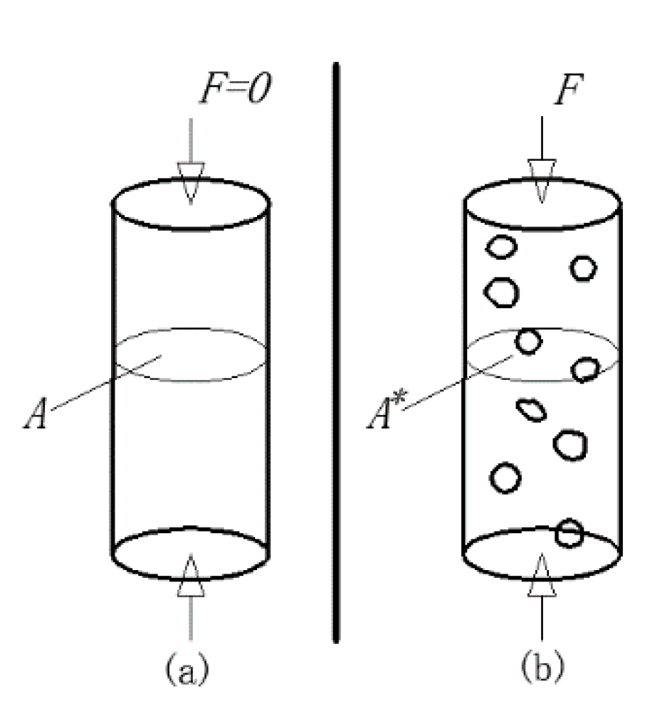
A straight rod uniaxial compression model was used to illustrate the effective stress.
Figure 1 shows an initial straight rod without damage and a straight rod with damage.
Assuming that the uniaxial pressure of the rod is
F, the initial cross-sectional area of the rod is
A, the damaged area is
A*, and the effective area of the rod is
. The damage variable is taken as a scalar that it is valid only in a 1D form. The continuity variable
Ψ describes the damage state of the material and is defined as:
On the original straight rod, the stress on the cross section
; and after the straight rod is damaged, the stress on the interface, that is, the stress on the effective cross section or the effective stress
, then
which is:
Principle of strain equivalence: The strain caused by stress σ acting on damaged materials is equivalent to the strain caused by effective stress acting on non-damaged materials. Therefore, the constitutive relationship of the damaged material can be obtained by the stress in the non-damaged material, namely:
The above formula is the constitutive relationship of damaged materials under one-dimensional conditions, which is:
The elastic modulus of the damaged material is .
2.2. The Variables of Seawater Erosion Grouting-Reinforced Body Damage
We can use grouting to reinforce a tiny unit in the body, assuming that its size is large enough to contain many tiny pore fissures, and small enough to be considered as a particle of continuous damage mechanics, ensuring that the distribution of microscopic pores and cracks in the reinforcement is uniform. The process of grouting-reinforced body damage can be regarded as the process of solidification damage caused by the initiation and development of micro-cracks or pores inside the cement hydration product and sand interface. The more micro-cracks and pores in the reinforcement, the greater the overall damage. Therefore, the damage variable of the grouting-reinforced body is positively related to the number of micro-cracks and pores N. The destruction of grouting-reinforced body is mainly due to the erosion of the original cement hydration product, resulting in the lack of grouting-reinforced body components, making the internal pores of the solid and the micro-cracks or pores at the interface between cement and sand increase. Therefore, it is reasonable to use the number of micro-cracks and pores N to describe the damage of the grouting-reinforced body.
According to the study of Grady and Kipp [
26],
N can be described by the material constant and the material strain, namely:
where
and
are the constants of the grouting-reinforced body material, and
ε is the strain of the material.
As shown in
Figure 2, the grouting-reinforced body uniaxial compression stress–strain curve shows that there are two main nodes in grouting-reinforced body stress–strain, which are divided into three stages. They are the downward convex elastic stage (OA segment), elastic compaction stage (AP segment) and failure stage (after P point). The deformation at the OA stage of the grouting-reinforced body uniaxial compression curve is mainly divided into two parts. One is the micro-cracks and pores of the grouting-reinforced body itself, which become smaller under the effect of applied pressure, resulting in false deformation. The other is that under the effect of grouting reinforcement external pressure, the real deformation is caused by the compression of the solid substrate itself. Therefore, in the OA stage, as the strain increases, the stress level is lower. The AP section of the uniaxial compression curve of the grouting-reinforced body is the stage of linear elastic response, that is, the stage of elastic compaction. The post-point P of the grouting-reinforced body uniaxial compression curve is the failure stage. Therefore, according to the line shape of the stress–strain curve of the grouting-reinforced body, the relationship between the damage variable and the microcracks and pores inside the grouting-reinforced body, and the continuum damage mechanics (CDM) [
27,
28], the grouting-reinforced body damage variable of the sand layer, is defined as:
2.3. Establishment of the Damage Model
According to the sand layer grouting-reinforced body stress–strain curve, the boundary conditions are as follows:
When , then (2) when then ;
where is the strain value at point A, and is the stress value at point A, is the peak strain value and is the peak stress value.
Bringing Equation (8) into Equation (6), and substituting it into the boundary condition (1), we obtain the stress–strain model under the condition of sand layer grouting-reinforced body uniaxial compression:
Derivation of Equation (9):
Substituting the boundary condition (2) into Equation (10) yields:
According to Equation (11), E
0,
, so
. That is say:
Substituting equation (12) into equation (8) yields:
Therefore, Equation (13) is the evolution equation of the damage variable when the sand layer is grouted and solid under uniaxial compression. It can be seen that the grouting-reinforced body damage variables are only related to the strain, the strain at point A, the peak stress, the strain corresponding to the peak stress, and the material property during the process of compressing the solid. Substituting Equation (13) into Equation (11) yields:
Equation (14) is the uniaxial compression damage model of sand layer grouting-reinforced body uniaxial compression.
3. Simulation Experiment of Ion Erosion in a Seawater Environment
3.1. Simulation Test Plan
The influence of the seawater environment on a grouting-reinforced body is mainly through chloride ion erosion of the hydration cement. This leads to the lack of grouting-reinforced body components, and increases the internal pores of the solid. At the same time, the microcracks or pores at the interface between cement and sand increase. The main factors affecting the cement hydration cement are the water–cement ratio and hydration degree of the slurry, and the hydration degree of the cement is directly related to the water–cement ratio of the slurry. Therefore, in order to study the erosion of the grouting-reinforced body in a seawater environment, the influence of the water–cement ratio and erosion time on the deterioration was studied.
(1) Slurry water–cement ratio
The common slurry used for sand layer grouting is cement slurry, where the water–cement ratio is 0.8:1, 1:1, 1.4:1, or 2:1.
(2) Grouting pressure
According to the occurrence conditions of infiltration grouting, as well as the laboratory experiment of infiltration grouting in a sand layer and a lot of engineering practice experience, when the pressure of infiltration grouting is 0.5 MPa, the infiltration and diffusion of slurry in the sand layer are sufficient. Therefore, the grouting pressure selected in this test was 0.5 MPa.
(3) Gradation of injected sand
According to the analysis of the sand permeability test and the reinforcement test, it can be seen that the sand grain gradation is in the range of 1~2 mm. The slurry diffuses fully in the sand layer to be injected. Therefore, the sand grain size selected in this test is in the range of 1~2 mm. The porosity and permeability coefficient are shown in
Table 1. The sand layer used in this sample is standard sand, and sand grains with a particle size of 1–2 mm are screened out. The porosity of the sample is tested according to the “Standard for Geotechnical Test Methods”, and the permeability of the sample is determined by the normal head penetration test.
(4) Curing environment
According to the design of the accelerated test, the long-term mechanical properties of grouting-reinforced bodies in a seawater environment were studied. The temperature of the curing box was 35 °C. The mass concentration of sodium chloride used in the curing liquid was 11.15%. The magnification was 88.15 times.
3.2. Experimental Scheme of Grouting Stage
- (1)
The penetration grouting test device is shown in
Figure 3. The permeable organic glass tube is fixed by a fastening device connected by a screw rod. A hard disk filter screen is arranged at the bottom of the organic glass tube to support the weight of the sand layer to be injected and prevent sand particles from being lost. The injected sand grains were layered into an organic glass tube, and the sensors were embedded. After the filling of the plexiglass tube is completed, the top of the plexiglass tube is closed and fixed on the test stand.
- (2)
Grouting pipes are connected. A pressure sensor, a flow sensor, a manual grouting pump and other devices are sequentially connected in series. Cement slurry is prepared according to the set water–cement ratio and placed in a slurry storage barrel for standby.
- (3)
Slurry is pumped by a manual grouting pump. The grouting rate is uniformly controlled by designing the grouting rate. The cement slurry in the slurry storage barrel is always stirred to prevent the slurry from settling.
- (4)
When the slurry emerges from the top of the plexiglass tube, the grouting stops and the grouting pipeline is cleaned.
3.3. Test Plan of the Curing Stage
Principles of accelerated test design.
In this test, accelerated erosion of the grouting-reinforced body is carried out through two parameters, temperature and concentration. By increasing the temperature, the activation energy of ions can be increased, thus accelerating the chemical reaction. The test climate and seawater are based on the data of the Qingdao Jiaozhou Bay subsea tunnel.
(1) Temperature: Arrhenius equation:
is the activation energy, and the Atkinson test value is 14,242 [
29].
T1 is the natural temperature.
T2 is the test temperature.
According to the actual measurement, the annual average temperature in Qingdao Jiaozhou Bay is 17 °C. In this test, the constant temperature is 35 °C, so the acceleration coefficient is 17.63.
(2) Concentration acceleration: The test of the chemical reaction order is accelerated.
where
is the indoor test grouting plus the chloride ion concentration (mass concentration) on a solid surface.
Cs is the concentration (mass concentration) of chloride ions on the surface of the grouting-reinforced body in seawater.
The mass concentration of sodium chloride in seawater of Jiaozhou Bay is 1.86~2.6%. The mass concentration of sodium chloride in this test is 11.15%, which is 5 times that in seawater.
According to the calculation method of the accelerated corrosion coefficient in laboratory tests, multiplying the accelerated coefficients of various factors, the deterioration accelerated coefficient in this test is 17.63 × 5 = 88.15.
Test steps for curing stage:
- (1)
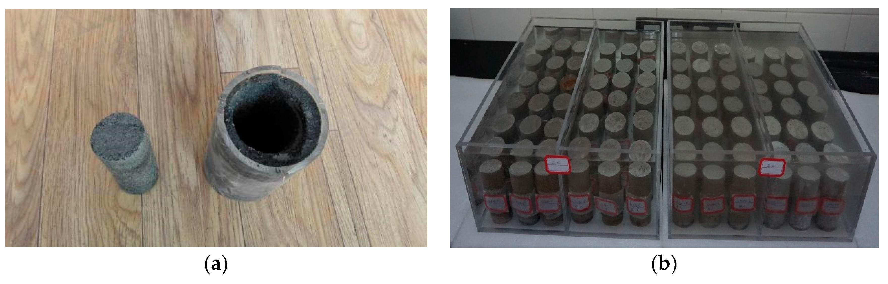
After the slurry is condensed, cut the plexiglass tube, and use a core remover to take a standard sample core at 20 cm from the grouting port. Put the test pieces into the curing box filled with sea water and maintain them. The process is shown in
Figure 4.
- (2)
Put the curing box in the standard curing box and select the constant temperature function of the standard curing box (without humidification). The temperature is kept at around 20 °C, and the water is changed every 7 days.
- (3)
After 28 days of curing, the sample is put into a new curing box. The temperature of the curing box is set and maintained at 35 °C. The curing liquid is prepared from crude salt. The mass concentration of sodium chloride is 11.15%, and the water is changed every 3 days.
- (4)
When the curing age reaches 3 days, 7 days, 14 days, 28 days, 56 days, 90 days, 180 days, 225 days and 270 days, the uniaxial compressive strength of the sample is tested.
4. Compression Stress–Strain Relationship in the Grouting-Reinforced Body
The stress–strain curve of the grouting-reinforced body under uniaxial compression can reflect its failure mode. At the same time, the mechanical properties of the grouting-reinforced body can be analyzed according to the trend of the curve. Therefore, in order to study the influence of a seawater environment on the erosion of the grouting-reinforced body, the stress–strain curve of the grouting-reinforced body was tested. It can be seen from the law of sand layer grouting reinforcement in a seawater environment that the solid strength reached stability at 365 days [
30]. That is to say, after a curing time of 1 year, the changes in the grouting-reinforced body strength and stress–strain are caused by seawater erosion.
Figure 5 shows the stress–strain curve when the strength of the grouting-reinforced body deteriorates to 60% of that in fresh water under different water–cement ratios. Each sample was used for nine sets of test experiments. The test time for samples with water–cement ratios of 0.8:1, 1:1, 1.4:1 and 2:1 was 75a, 60a, 30a, and 15a, respectively [
30].
It can be seen from the analysis chart that the stress–strain changes of the grouting-reinforced body caused by seawater erosion show different trends with different slurry water–cement ratios. In the early stage of strain, that is, the stage of elastic deformation, with the increase of the slurry water–cement ratio, the curve is more gentle, and the strain value at the critical point of elastic deformation is greater. The main reason is that as the water–cement ratio of the slurry increases, the degree of cement hydration reaction weakens, and the remaining water in the slurry increases. After the cement hydration reaction ends, there is more water remaining in the grouting reinforcement body, resulting in increased porosity of the grouting-reinforced body. Under the condition that the grouting-reinforced body is subjected to uniaxial compression, the “false strain” caused by the squeezing pores increases, so that the strain of the solids increases faster and the stress increases more slowly.
When the stress–strain curve of the grouting solid reaches the peak, the smaller the water–cement ratio, and the sharper the curve at the peak. That is to say, the greater the water–cement ratio, the slower the change when the stress reaches the peak. The grouting-reinforced body with a high water–cement ratio has better ductility, while the grouting-reinforced body with a low water–cement ratio has relatively low ductility due to the high degree of hydration. When the peak value is reached, the grouting and solid with water–cement ratios of 0.8:1, 1:1, 1.4:1 and 2:1 have a strain of 0.01 mm, 0.015 mm, 0.02 mm, and 0.03 mm, and peak stress of 13.8 MPa, 8.7 MPa, 4.9 MPa, and 1.7 MPa. It can be seen that with the increase of the grouting-reinforced body water–cement ratio, the stress of the solid at the peak value decreases and the strain increases, and the hydration reaction degree of the slurry plays a decisive role.
After the grouting-reinforced body stress exceeds the peak value, the stress–strain curve shows the opposite rule before the peak value. As the water–cement ratio increases, the curve decreases more rapidly. When the water–cement ratio is 0.8:1, the change in peak grouting failure strain is about 0.015 mm. When the water–cement ratio is 1:1, the change in peak grouting failure strain is about 0.01 mm. When the water–cement ratio is 1.4:1, the change in grouting strain is about 0.008 mm. When the water-cement ratio is 2:1, the change in grouting strain is about 0.005 mm. It can be seen that with the increase of the slurry water–cement ratio, the strain after grouting reaches the peak gradually decreases. Since the pores in the reinforcement body have been squeezed at the peak, the strain after the peak depends on the degree of cement hydration The larger the slurry, the lower the degree of cement hydration and the worse the grouting-reinforced body plasticity.
5. Determination of Constitutive Parameters of Grouting-Reinforced Body Damage
According to the uniaxial compression damage constitutive model (Formula (14)) of a sand layer grouting-reinforced body under seawater erosion conditions, it can be seen that the values of
,
,
and
n need to be clarified before the constitutive model is determined. From the stress–strain curve of grouting-reinforced body compression under a seawater environment, it was found that the load value of point A is about 15% of the peak load. Therefore, the criterion for selecting A is the stress and strain point corresponding to 15% of the peak load. As for the values of
,
and
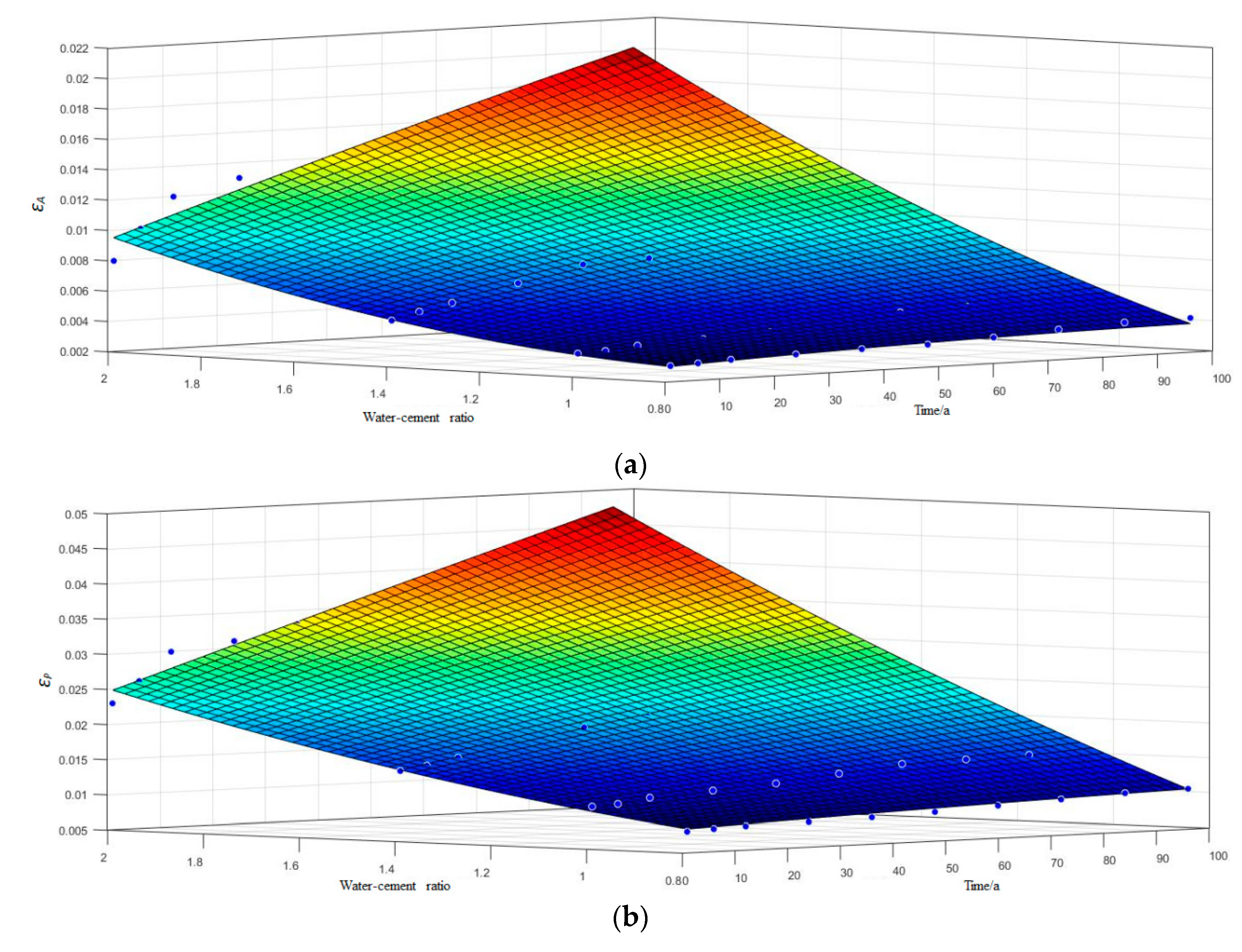
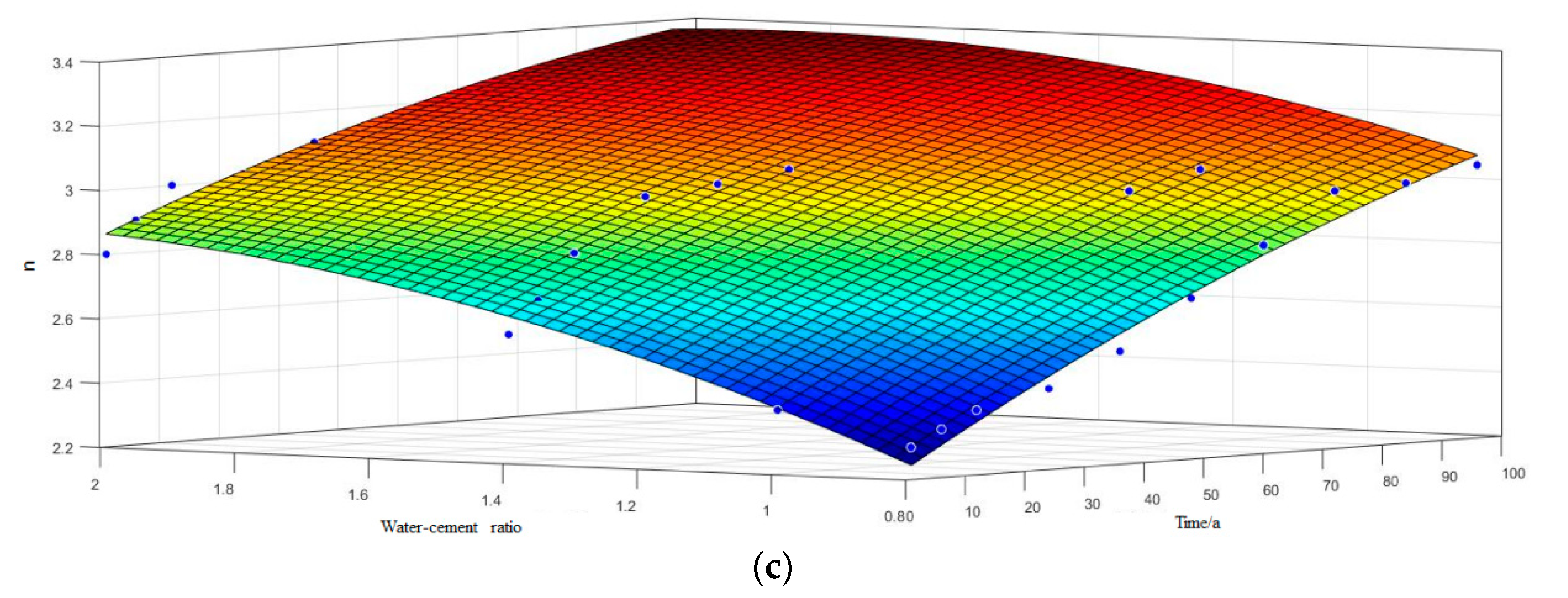
n, the formula is fitted through the stress–strain test results of the grouting-reinforced body under different grout water–cement ratios and different erosion times. The result is shown in
Figure 6.
εA,
εP, and
n all change with the change of slurry water–cement ratio and seawater erosion time. According to the form of its related curve, the function
is defined. The meaning of
Nwc is the water–cement ratio of the slurry. Fitting the data to obtain the quantitative relationship of
εA,
εP and
n with the water–cement ratio of slurry and erosion time determines the grouting-reinforced body damage model in a sea water environment. The fitted constant values are shown in
Table 2.
6. Discussion
This article describes the damage of adding solids after seawater erosion, and analyzes its stress–strain curve and the relationship between damage variables and grouting solids. It also establishes a constitutive model of solids added to seawater. The following aspects will be discussed later. (1) Relationship between the water environment and solid damage; (2) The damage model and impacts of adding solids in a seawater environment; (3) Prediction of the long-term durability of the added solids to ensure the safety of the tunnel operation over a long life cycle.
7. Conclusions
- (1)
Based on effective stress and damage mechanics, solid damage after seawater erosion was analyzed to obtain its stress–strain curve and the relationship between damage variables and micro-cracks and pores inside the solid added by grouting. A constitutive model of solid damage in seawater environment is established.
- (2)
The acceleration test of grouting-reinforced body erosion under a seawater erosion environment was designed by using the two factors of temperature and concentration, which can model the accelerated degradation of solid addition.
- (3)
With the increase of the water–cement ratio of the slurry, the peak strain and limit strain of the additive solid both increase, which also corresponds to the analysis of the established model. The peak strain and limit strain of the grouting-reinforced body formed by grout with a water–cement ratio of 2:1 are three times that of grout with a water–cement ratio of 0.8:1.
- (4)
The constitutive model of the sand layer and solid degradation under a seawater environment was finally determined through the stress–strain curve after solid degradation, which is of great significance for improving the degradation theory under a seawater environment and ensuring the long life and safety of tunnel operations.

 ,
, 


