Application of Rehabilitation and Active Pressure Control Strategies for Leakage Reduction in a Case-Study Network


Abstract
1. Introduction
2. Materials and Methods
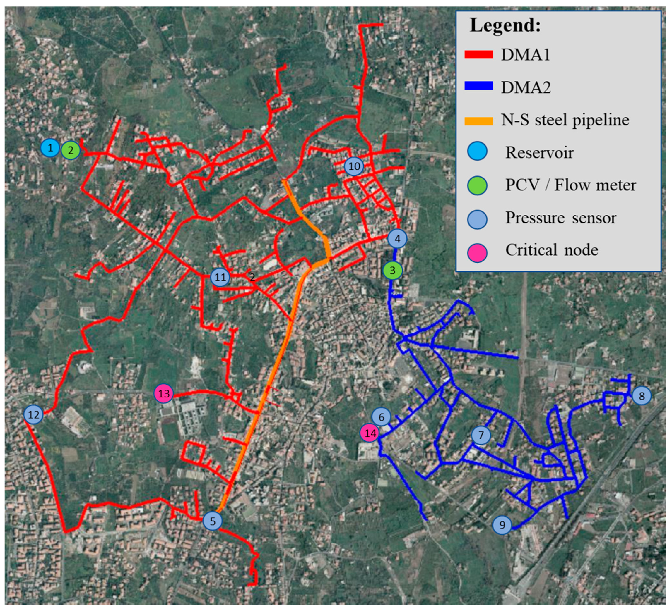
2.1. Case-Study Network
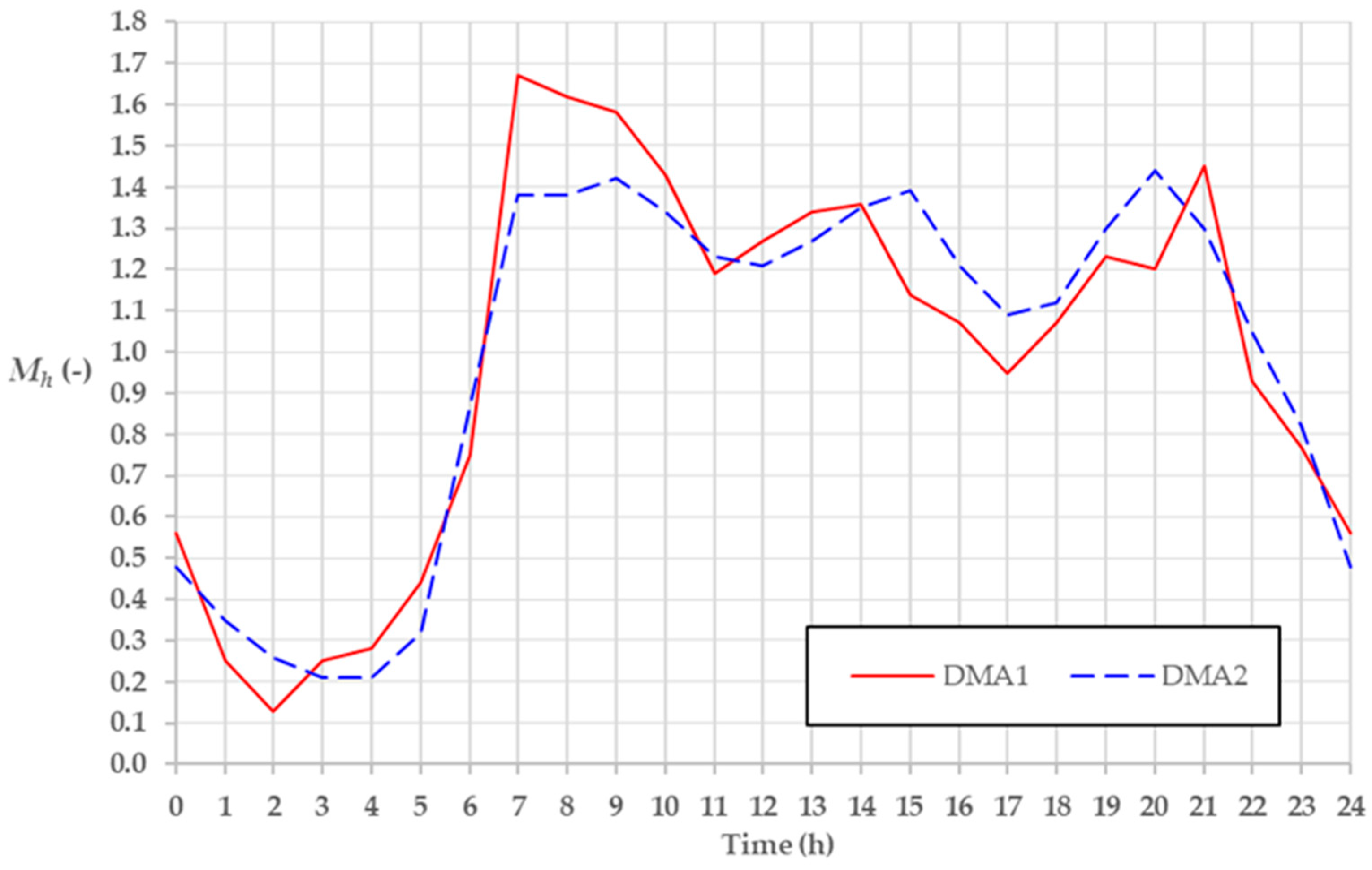
2.2. Monitoring Campaign
2.3. Model of the Network
2.4. Model Calibration
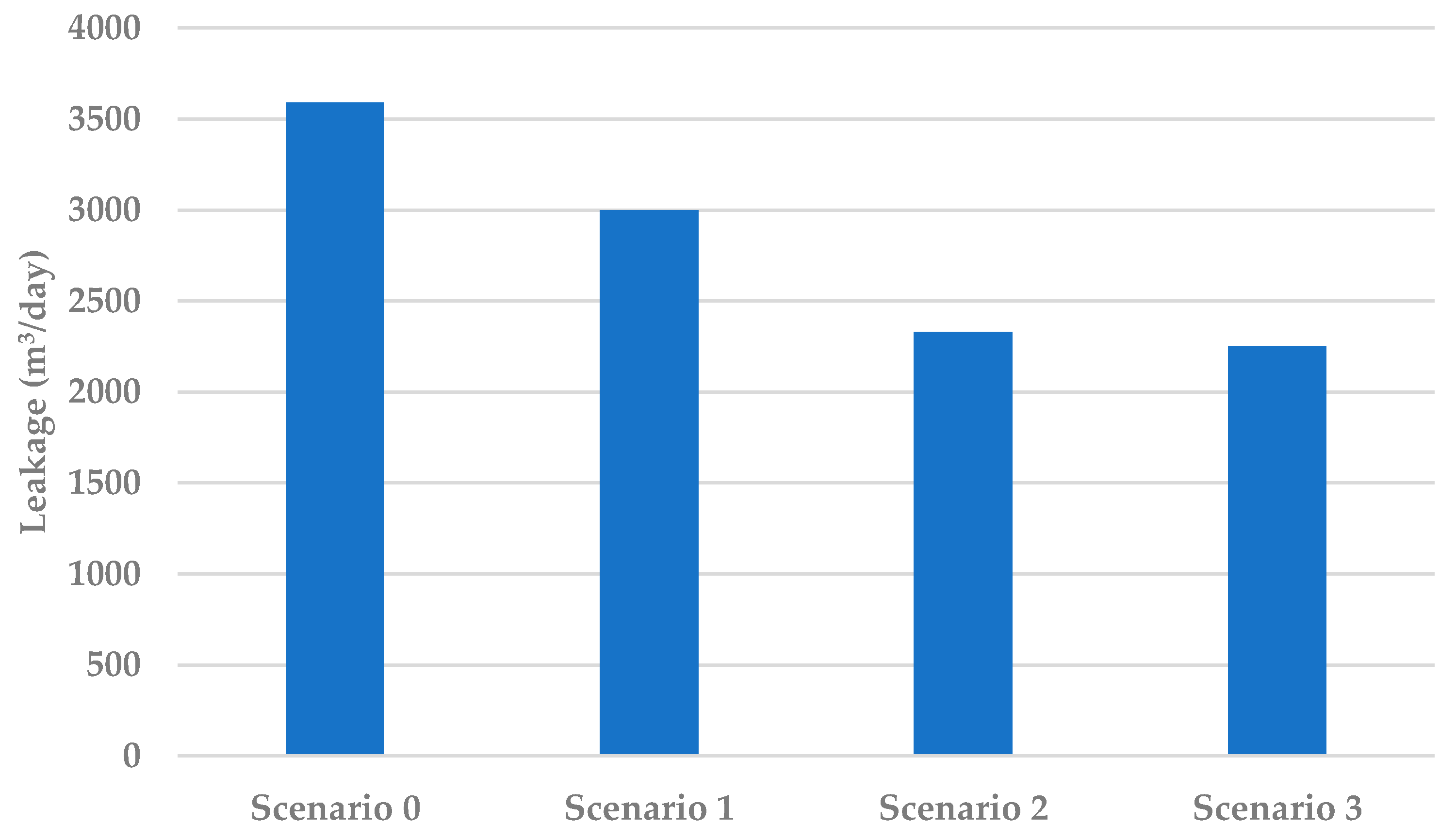
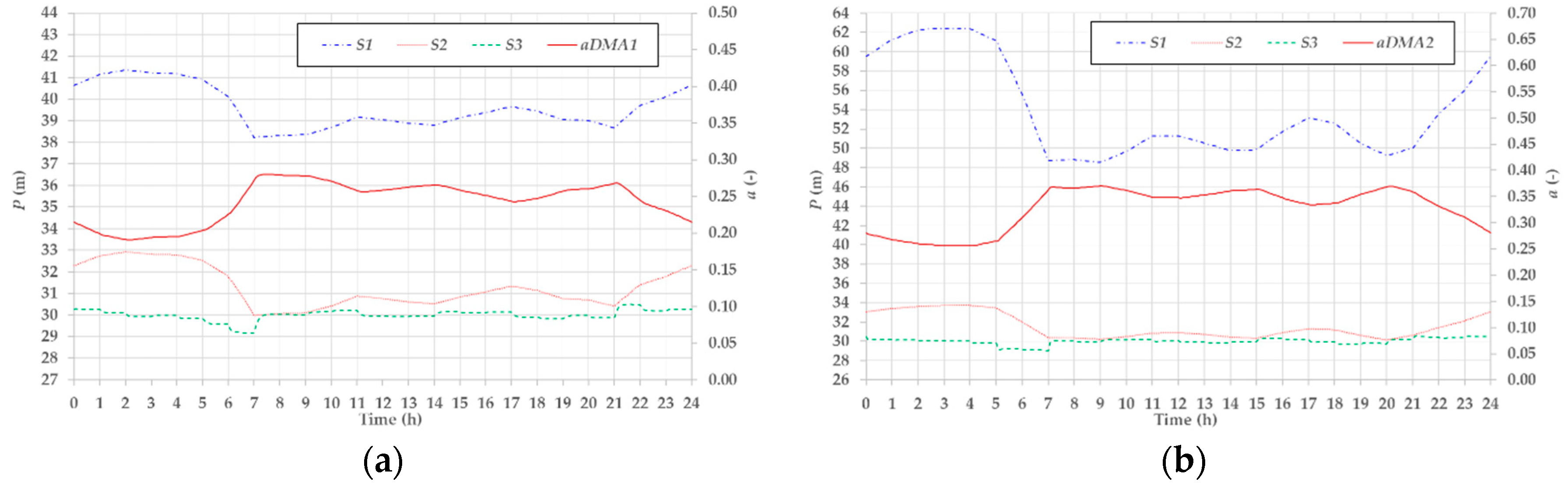
2.5. Scenarios of Simulation
3. Results
3.1. Results of the Monitoring Campaign and Leakage Level Estimation
3.2. Results of Model Calibration
3.3. Results of Simulation Scenarios
4. Conclusions
Author Contributions
Funding
Conflicts of Interest
References
- Berardi, L.; Laucelli, D.B.; Simone, A.; Mazzolani, G.; Giustolisi, O. Active Leakage Control with WDNetXL. Procedia Eng. 2016, 154, 62–70. [Google Scholar] [CrossRef]
- Wu, Z.Y.; Sage, P.; Turtle, D. Pressure-Dependent Leak Detection Model and Its Application to a District Water System. J. Water Resour. Plan. Manag. 2010, 136, 116–128. [Google Scholar] [CrossRef]
- Romano, M.; Kapelan, Z.; Savic, D. Geostatistical techniques for approximate location of pipe burst events in water distribution systems. J. Hydroinform. 2013, 15, 634–651. [Google Scholar] [CrossRef]
- Berardi, L.; Giustolisi, O.; Kapelan, Z.; Savic, D. Development of pipe deterioration models for water distribution systems using EPR. J. Hydroinform. 2008, 10, 113–126. [Google Scholar] [CrossRef]
- Thornton, J. Water Loss Control Manual; McGraw Hill Professional: New York, NY, USA, 2002. [Google Scholar]
- Ciaponi, C.; Franchioli, L.; Murari, E.; Papiri, S. Procedure for Defining a Pressure-Outflow Relationship Regarding Indoor Demands in Pressure-Driven Analysis of Water Distribution Networks. Water Resour. Manag. 2015, 29, 817–832. [Google Scholar] [CrossRef]
- Le Gat, Y.; Eisenbeis, P. Using maintenance records to forecast failures in water networks. Urban Water 2000, 2, 173–181. [Google Scholar] [CrossRef]
- Prescott, S.L.; Ulanicki, B. Improved Control of Pressure Reducing Valves in Water Distribution Networks. J. Hydraul. Eng. 2008, 134, 56–65. [Google Scholar] [CrossRef]
- Nicolini, M.; Zovatto, L. Optimal Location and Control of Pressure Reducing Valves in Water Networks. J. Water Resour. Plan. Manag. 2009, 135, 178–187. [Google Scholar] [CrossRef]
- Pezzinga, G.; Gueli, R. Discussion of “Optimal Location of Control Valves in Pipe Networks by Genetic Algorithm” by LFR Reis, RM Porto, and FH Chaudhry. J. Water Resour. Plan. Manag. 1999, 125, 65–67. [Google Scholar] [CrossRef]
- Creaco, E.; Pezzinga, G. Comparison of Algorithms for the Optimal Location of Control Valves for Leakage Reduction in WDNs. Water 2018, 10, 466. [Google Scholar] [CrossRef]
- Campisano, A.; Modica, C.; Reitano, S.; Ugarelli, R.; Bagherian, S. Field-Oriented Methodology for Real-Time Pressure Control to Reduce Leakage in Water Distribution Networks. J. Water Resour. Plan. Manag. 2016, 142, 04016057. [Google Scholar] [CrossRef]
- Berardi, L.; Simone, A.; Laucelli, D.B.; Ugarelli, R.M.; Giustolisi, O. Relevance of hydraulic modelling in planning and operating real-time pressure control: Case of Oppegård municipality. J. Hydroinform. 2018, 20, 535–550. [Google Scholar] [CrossRef]
- Page, P.R.; Abu-Mahfouz, A.M.; Mothetha, M.L. Pressure Management of Water Distribution Systems via the Remote Real-Time Control of Variable Speed Pumps. J. Water Resour. Plan. Manag. 2017, 143, 04017045. [Google Scholar] [CrossRef]
- Creaco, E.; Walski, T. Operation and Cost-Effectiveness of Local and Remote RTC. J. Water Resour. Plan. Manag. 2018, 144, 04018068. [Google Scholar] [CrossRef]
- Campisano, A.; Schilling, W.; Modica, C. Regulators’ setup with application to the Roma–Cecchignola combined sewer system. Urban Water 2000, 2, 235–242. [Google Scholar] [CrossRef]
- Campisano, A.; Creaco, E.; Modica, C. RTC of Valves for Leakage Reduction in Water Supply Networks. J. Water Resour. Plan. Manag. 2010, 136, 138–141. [Google Scholar] [CrossRef]
- Giustolisi, O.; Ugarelli, R.M.; Berardi, L.; Laucelli, D.B.; Simone, A. Strategies for the electric regulation of pressure control valves. J. Hydroinform. 2017, 19, 621–639. [Google Scholar] [CrossRef]
- Bakker, M.; Rajewicz, T.; Kien, H.; Vreeburg, J.H.G.; Rietveld, L. Advanced control of a water supply system: A case study. Water Pr. Technol. 2014, 9, 264–276. [Google Scholar] [CrossRef]
- Page, P.R.; Abu-Mahfouz, A.M.; Yoyo, S. Parameter-Less Remote Real-Time Control for the Adjustment of Pressure in Water Distribution Systems. J. Water Resour. Plan. Manag. 2017, 143, 04017050. [Google Scholar] [CrossRef]
- Creaco, E.; Campisano, A.; Modica, C. Testing behavior and effects of PRVs and RTC valves during hydrant activation scenarios. Urban Water J. 2018, 15, 218–226. [Google Scholar] [CrossRef]
- Eliades, D.G.; Kyriakou, M.; Vrachimis, S.; Polycarpou, M.M. EPANET-MATLAB toolkit: An open-source software for interfacing EPANET with MATLAB. In Proceedings of the 14th International Conference on Computing and Control for the Water Industry (CCWI 2016), Amsterdam, The Netherland, 1–4 November 2016. [Google Scholar]
- Rossman, L.A. EPANET 2: Users Manual; National Risk Management Research Laboratory: Cincinnati, OH, USA, 2000. [Google Scholar]
- Williams, G.S.; Hazen, A. Hydraulic Tables: The Elements of Gagings and the Friction of Water Flowing in Pipes, Aqueducts, Sewers, etc. as Determined by the Hazen and Williams Formula and the Flow of Water Over Sharp-Edged and Irregular Weirs, and the Quantity Discharged, as Determined by Bazin’s Formula and Experimental Investigations Upon Large Models; J. Wiley & Sons: Hoboken, NJ, USA, 1908. [Google Scholar]
- Germanopoulos, G. A technical note on the inclusion of pressure dependent demand and leakage terms in water supply network models. Civ. Eng. Syst. 1985, 2, 171–179. [Google Scholar] [CrossRef]
- Goodwin, S.J. The Results of the Experimental Programme on Leakage and Leakage Control; WRC Environmental Protection: Swindon, UK, 1980. [Google Scholar]
- Greyvenstein, B.; Van Zyl, J.E. An experimental investigation into the pressure—leakage relationship of some failed water pipes. J. Water Supply Res. Technol. 2007, 56, 117–124. [Google Scholar] [CrossRef]
- Farley, M.; Trow, S. Losses in Water Distribution Networks: A Practitioners’ Guide to Assessment, Monitoring and Control. Water Intell. Online 2015, 4. [Google Scholar] [CrossRef]
- Al-Ghamdi, A.S. Leakage–pressure relationship and leakage detection in intermittent water distribution systems. J. Water Supply Res. Technol. 2011, 60, 178–183. [Google Scholar] [CrossRef]
- Ferrante, M. Experimental Investigation of the Effects of Pipe Material on the Leak Head-Discharge Relationship. J. Hydraul. Eng. 2012, 138, 736–743. [Google Scholar] [CrossRef]
- Di Nardo, A.; Di Natale, M.; Gisonni, C.; Iervolino, M. A genetic algorithm for demand pattern and leakage estimation in a water distribution network. J. Water Supply Res. Technol. 2015, 64, 35–46. [Google Scholar] [CrossRef]
- Campisano, A.; Modica, C.; Musmeci, F.; Bosco, C.; Gullotta, A. Laboratory experiments and simulation analysis to evaluate the application potential of pressure remote RTC in water distributions networks. Water Res. 2020, 183, 116072. [Google Scholar] [CrossRef] [PubMed]
- Ziegler, J.G.; Nichols, N.B. Optimum Settings for Automatic Controllers. J. Dyn. Syst. Meas. Control. 1942, 115, 220–222. [Google Scholar] [CrossRef]
- Creaco, E.; Franchini, M. A new algorithm for real-time pressure control in water distribution networks. Water Supply 2013, 13, 875–882. [Google Scholar] [CrossRef]
- Letting, L.; Hamam, Y.; Abu-Mahfouz, A.M. Estimation of Water Demand in Water Distribution Systems Using Particle Swarm Optimization. Water 2017, 9, 593. [Google Scholar] [CrossRef]
- Tucciarelli, T.; Criminisi, A.; Termini, D. Leak Analysis in Pipeline Systems by Means of Optimal Valve Regulation. J. Hydraul. Eng. 1999, 125, 277–285. [Google Scholar] [CrossRef]
- Maskit, M.; Ostfeld, A. Leakage Calibration of Water Distribution Networks. Procedia Eng. 2014, 89, 664–671. [Google Scholar] [CrossRef]


| DMA1 | DMA2 | ||||||||||
|---|---|---|---|---|---|---|---|---|---|---|---|
| Flow | Pressure | Flow | Pressure | ||||||||
| Node | 2 | 10 | 11 | 12 | 4 | 5 | 3 | 6 | 7 | 8 | 9 |
| MAPE | 0.017 | 0.037 | 0.040 | 0.032 | 0.031 | 0.022 | 0.006 | 0.016 | 0.014 | 0.020 | 0.014 |
| RMSPE | 0.020 | 0.045 | 0.051 | 0.038 | 0.039 | 0.026 | 0.008 | 0.020 | 0.017 | 0.025 | 0.018 |
© 2020 by the authors. Licensee MDPI, Basel, Switzerland. This article is an open access article distributed under the terms and conditions of the Creative Commons Attribution (CC BY) license (http://creativecommons.org/licenses/by/4.0/).
Share and Cite
Bosco, C.; Campisano, A.; Modica, C.; Pezzinga, G. Application of Rehabilitation and Active Pressure Control Strategies for Leakage Reduction in a Case-Study Network. Water 2020, 12, 2215. https://doi.org/10.3390/w12082215
Bosco C, Campisano A, Modica C, Pezzinga G. Application of Rehabilitation and Active Pressure Control Strategies for Leakage Reduction in a Case-Study Network. Water. 2020; 12(8):2215. https://doi.org/10.3390/w12082215
Chicago/Turabian StyleBosco, Camillo, Alberto Campisano, Carlo Modica, and Giuseppe Pezzinga. 2020. "Application of Rehabilitation and Active Pressure Control Strategies for Leakage Reduction in a Case-Study Network" Water 12, no. 8: 2215. https://doi.org/10.3390/w12082215
APA StyleBosco, C., Campisano, A., Modica, C., & Pezzinga, G. (2020). Application of Rehabilitation and Active Pressure Control Strategies for Leakage Reduction in a Case-Study Network. Water, 12(8), 2215. https://doi.org/10.3390/w12082215