Article

Effect of Inlet/Outlet Configuration on Water Quality in a Rainwater Harvesting Tank

Department of Civil & Environmental Engineering, College of Engineering, Seoul National University, 1, Gwanak-ro, Gwanak-gu, Seoul 08826, Korea
*
Author to whom correspondence should be addressed.
Water 2020, 12(7), 1970; https://doi.org/10.3390/w12071970
Submission received: 7 May 2020 / Revised: 12 June 2020 / Accepted: 10 July 2020 / Published: 12 July 2020
(This article belongs to the Section Water Use and Scarcity)

Abstract

:
Rainwater harvesting (RWH) has attracted global attention as a solution for the urban water crisis; however, the water quality can be impacted by particulate matter and soluble contaminants. Therefore, the inlet and outlet configurations of the storage tank should be designed to minimize bottom sediment resuspension and prevent the transport of soluble contaminants. Thus, this study investigated the effects of the inlet and outlet configurations of a rainwater storage tank on particle resuspension and residence time distribution for an instantaneous input of a conservative tracer. It was observed that J type inlets can reduce sediment resuspension by more than 50% while detaining and mixing a conservative pollutant, thus preventing the concentration from reaching the outlet as a plug flow. Although inlet height did not have a significant influence on the quality of water at the outlet, parameters such as inflow velocity and outlet height exerted a considerable influence on sludge resuspension and residence time distribution. The experiments also highlighted the importance of regulating the initial water level of the storage tank and regular flushing of bottom sediment to maintain the stored water quality.

1. Introduction

Potable water is an essential human requirement. However, due to the spatial and temporal variation of water resources, at least 10% of the global population has no access to potable water [1]. As a result, approximately 500,000 children die every year worldwide [2]. This crisis is exacerbated by climate change, environmental pollution, and rapid urbanization, which cause existing water bodies to become depleted or unusable. Rainwater has been identified as an excellent alternative water source due to its short pollutant inflow route [3]. Rainwater can be collected from impervious surfaces, such as the roof of a house, as shown in Figure 1a, then stored and treated to meet the water quality standards for its intended use. This practice of rainwater harvesting (RWH) in urban centers has the potential to avert urban crises not only by providing an alternative source of water, but also by reducing urban runoff and the demand imposed on central drinking water supply systems [4,5,6].
Although the benefits of RWH are significant, several have reported poor harvested rainwater quality due to high concentrations of particulate matter and chemicals such as herbicides and pesticides [7,8]. The majority of these pollutants enter the RWH system through wet and dry deposition on the roof surface, a lack of maintenance, and leaching from built materials, among which dry and wet deposition on the catchment surface represents the main pollutant source [9,10]. After a long dry period, the initial part of a storm event will transport very high concentrations of accumulated pollutants from the roof top to the RWH system [11,12]. As particulate matter in the initial water inflow can affect the disinfection process and clog the piping system, the concentration of suspended solids in the water should be reduced by sedimentation during storage. Additionally, the soluble contaminants entering the system should be mixed, diluted, and retained to prevent the contaminants from rapidly reaching the end-use point in high concentrations. Therefore, the individual elements comprising RWH systems should be designed with these objectives in mind.
A common RWH system (Figure 1a) may contain a first-flush device, a storage tank, and a point-of-use disinfection unit. Of these units, the first-flush device and storage tank primarily contribute to removing particulate matter and diluting the instantaneous input of soluble contaminants. A first-flush unit can remove a significant amount of particulate matter and soluble contaminants from the initial part of rainfall; however, RWH systems in most developing countries are still primitive in design and do not contain a first-flush device [13]. Moreover, low rainfall intensity and prolonged dry periods may result in pulse contaminant inputs partially bypassing the first-flush device [14]. Therefore, the design of the storage tank in an RWH system is vital because any pollutants bypassing the first-flush device will enter the RWH tank. The most important process in a storage tank is the sedimentation of suspended solids, hydrocarbons, and heavy metals associated with particles. Sediment in an RWH tank can hold a significant amount of lead compared to the overlying water column [15]; therefore, resuspension of this bottom sediment could degrade the stored water quality, which can occur due to low cistern levels or the turbulent influx of rainwater during a rainfall event [16]. References [3,17,18,19] observe that, instead of a typical inlet arrangement (Figure 1b), a calmed inlet reduces the resuspension of sludge (Figure 1c). Further, [17,20] suggest the use of floating outlets that allows the water near surface where suspended particles are at the lowest concentration to be taken up by pumps. However, the authors did not investigate the effect of inlet height/outlet height configurations on sediment resuspension. Reference [21] extensively experimented with the effects of inlet position, outlet height, and inlet height with a normal I type inlet. The authors conclude that inlet height has no significant influence, and that high inflow rates, higher bottom sediment thickness, and centrally located inlets could increase the bottom sediment resuspension. However, their work did not investigate how the calm inlet could influence bottom sediment resuspension with varying inlet/outlet configurations. Similarly, no previous research discusses the effect of the inlet and outlet configurations of the storage tank of an RWH system on the dilution and residence time of a soluble pollutant input.
RWH systems in developing countries consist of only an RWH tank due to financial constraints of people and the government [22,23]. If a change of inlet/outlet configurations could have a positive impact on water quality, it would be economically feasible to adopt them in developing countries. Moreover, organizations promoting rainwater, such as governments of developing countries and NGOs, will be able to assist communities financially in such an endeavor. Therefore, this study conducts experiments to determine the influence of different types of inlet/outlet configurations and operational parameters (initial water level and mass of bottom sediment) on minimizing bottom sediment resuspension and maximizing residence time of a conservative pollutant (tracer). The results of this study are used to propose recommendations for new RWH tank design as well as modifications to existing tanks.

2. Materials and Methods

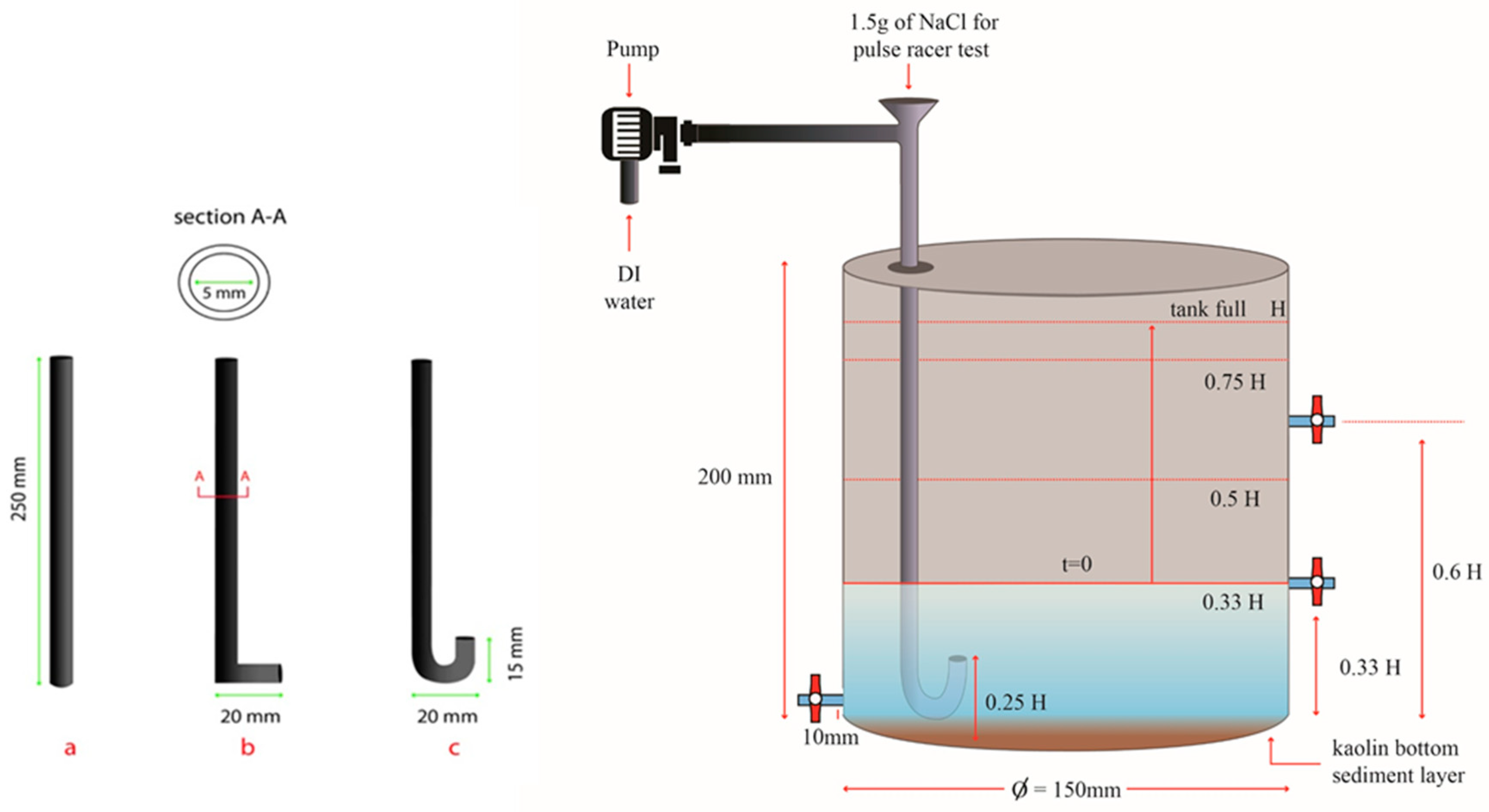
2.1. Experimental Method

2.1.1. Sediment Resuspension Experiment

The shape, capacity, and dimensions of RWH tanks vary according to the manufacturer in each country. Therefore, a cylindrical acrylic laboratory scale RWH tank was fabricated with a diameter of 15 cm and a height of 20 cm for the purpose of the study. The tank was fabricated by downscaling by a factor of 10 from domestic scale cylindrical RWH tanks widely used in developing countries such as India and Sri Lanka, while keeping geometric similarity [19,24]. The height of the tank at a volume of 3 L (H) was calculated and outlets were made at 0.33 H and 0.6 H. Three types of inlets were fabricated, as shown in Figure 2, each with an internal diameter of 5 mm and a height of 25 cm. The inlet diameter was selected considering the pipe velocity range stipulated in [25]. Then, 2 g of reagent-grade kaolin clay (Al2H4O9Si2, molecular weight: 258.156 g/mol) purchased from [26], was mixed with 500 mL of double-distilled water. The solution was then introduced to the tank and another 500 mL of double-distilled water was added so that the kaolin concentration in the tank was 2 g/L. Then, the clay solution was left for 24 h to facilitate clay particle sedimentation. After 24 h, double-distilled water was introduced by a pump (FH100, Thermo scientific) until the tank reached its full capacity of 3 L. The inlet/outlet configurations were varied, but the other parameters were kept constant, as described in Table 1. Turbidity (Hach 2100Q, Loveland, CO, USA, standard error (±2%) was measured at 30 s intervals after the water was introduced to the system by collecting 25 mL water samples from the outlet at 0.33 H for 2 min. As this paper investigates the influence of inlet/outlet configurations on bottom sediment resuspension while there is an inflow, turbidity was measured until the tank reached full capacity. Further, to verify the resuspension of sediments, water was drained from a drain valve at a height of 1 cm from the bottom and then analyzed for suspended solids concentration. The 25 mL samples collected for turbidity measurement were also added to the drained water prior to the suspended solids analysis.

2.1.2. Pulse Conservative Tracer Experiment

The tank and the experimental set up (Figure 2) were similar to those of the sediment resuspension experiment. Double-distilled water was introduced at 1.5 L/min and 2.2 L/min using a metering pump (FH100, Thermo scientific). Flow rates were determined to capture the most frequent rainfall intensity of 70 mm/h (for a 100 m2 surface) during summer in South Korea [27]. Reagent-grade sodium chloride (salt), purchased from [26], was used as the conservative tracer. Sodium chloride was selected because it is found as a common pollutant in RWH systems near coastal areas and it is a conservative material that is widely used in tracer studies. The tracer was introduced to the system instantaneously after the system reached a steady state. Inflow was continued at a steady state, the inlet (I, L, J type inlets) was placed at 0.25 H, and the water level in the tank was maintained at 3 L. The outflow valve at 0.33 H was kept open and, after introduction of the tracer, a water sample was collected from the outlet every 30 s for 15 min. The samples collected were then analyzed for conductivity using a portable conductivity meter (Orion star A329, Beverly, MA, USA). The conductivity meter was calibrated using 1413 mg/L and 12.9 mg/L standard solutions. Conductivity was converted to concentrations using the inbuilt conversion function of the conductivity meter (with 0.5% of reading ±1-digit accuracy), which was validated by manual calculations.
To investigate the effect of inlet height, the J type inlet was placed at 0.25 H, 0.5 H, and 0.75 H and the tracer test was conducted using the method described above with the outlet fixed at 0.33 H. Similarly, the effect of outlet height was investigated by operating the outlets at 0.33 H and 0.6 H with the inlet fixed at 0.25 H. All experimental details are provided in Table 1.

2.2. Analysis Method: Residence Time Distribution (RTD)

The RTD represents the time a tracer spends in the reactor and can be used to analyze steady-flow systems with dimensionless parameters to describe concentration and time [28]. In the context of rainwater harvesting systems, a nonplug flow RTD with a higher residence time is preferable because it provides time for suspended particles to settle and prevents contaminants from reaching the outlet in high concentrations. Therefore, understanding the RTD of an RWH tank is beneficial and the RTD can be obtained by plotting the dimensionless tracer mass exiting the outlet with dimensionless time. The dimensionless mass (concentration) exiting the outlet (RTD function), E(t), can be defined as:
E ( t ) = C i   t ¯ i C k   Δ t i
where Ci is the measured tracer concentration at the outlet, Ck is 0.5 × (Ci + Ci−1), and t ¯ is the mean measured residence time, which is the average time tracer materials stay within the tank and can be calculated as:
t ¯ = i t i   C i   Δ t i i C i   Δ t i
Mean residence time of a tank or a reactor depends on the geometry, flow, and flow velocities. To make the RTD applicable for larger tanks with similar geometrical and flow conditions, a dimensionless parameter for time could be introduced where time is given as a fraction of mean residence time or hydraulic retention time of the tank. The dimensionless time parameter, θ, can be expressed as:
θ i = t i   t ¯
A cumulative RTD (F), the cumulative fraction of tracer mass that has exited the tank, can be defined as:
F ( t ) = i E ( t i ) + E ( t i 1 ) Δ t i 2
and the variance of the RTD curve σ2 can be derived from the tracer data as follows:
σ 2 = i t i 2   C i   Δ t i i   C i   Δ t i t ¯ 2

3. Results and Discussion

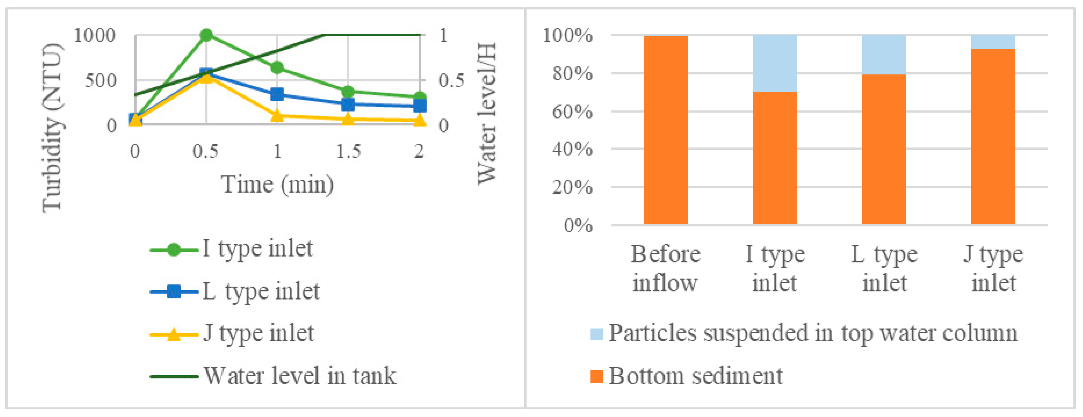
3.1. Effect of Inlet Type

When water was introduced to the system, turbidity first increased due to resuspension then decreased because of dilution (Figure 3). Further, with time, the rising water levels provide cushioning to the incoming water, preventing further resuspension. Thus, the initially resuspended particles get dispersed in a larger volume, resulting in a lower turbidity. However, the final turbidity level and the initial rise in turbidity in the tank with the J type inlet was approximately two times lower than that with an I type inlet (Figure 3). Designs in references [3,17,18,19] incorporated J type inlets, considering the benefit of reduced particle resuspension. Water flow from the inlet stirred the bottom sediments, forcing the settled particles to become resuspended in the water column. This phenomenon was further illustrated by the mass distribution of kaolin clay between the water column and the bottom sediment (Figure 3), i.e., the J type inlet exhibited the smallest amount of suspended particulate matter of all inlet types.
The normalized residence time calculated (Table 2) for the pulse salt tracer input for all inlet types was plotted for a flow rate of 2.2 L/min (Figure 4). The J type inlet exhibited almost identical performance to a continuous flow stirred-tank reactor (CSTR). This is probably due to the turbulence created at the J shaped bend in the inlet, which enabled uniform mixing of the fluids prior to entering the tank. The upward flow induced by the J shaped inlet allowed further mixing of the fluids, resulting in very similar behavior to the CSTR. With I and L type inlets, the RWH tank exhibited performance between that of a CSTR and a plug flow reactor (PFR) (Figure 4). References [29,30] reported similar results for sedimentation tanks and ponds with the typical inlet conditions used for storm water management.
The mean residence time ( t ¯ ) increased from the I type inlet to the J type inlet by almost 18% (Table 3). Further, in Table 3, it can be observed that θ at 95% mass recovery has also increased. Therefore, a conservative pollutant concentration entering the RWH system with a J type inlet is likely to remain in the tank for a longer time. This is beneficial for preventing pollutants from entering another tank or other components of the RWH system by allowing the user more time to devise a response, for example, isolation of the contaminated unit or flushing of the tank. Further, higher residence time gives suspended solids in the incoming water more time to settle before reaching the outlet. RTD graphs for J typeinlet revealed very long tails that were likely due to the dead space created. Fluids beneath the inlet would have been lightly disturbed, allowing the fluid below the inlet to become trapped within the RWH tank. This was further highlighted by the decreasing mean mass recovery rates (Table 3).

3.2. Effect of Inlet Height

Similar to observations by [21] with I type inlets, the inlet height had a minimal impact on sediment resuspension, which was also noted with a J type inlet. This was possibly due to the upward flow conditions created by the inlet, regardless of the height that the inlet was placed. However, there was a slight increase in both turbidity and suspended solids when the inlet height was increased from 0.1 to 0.5 H (Figure 5). The initial water height for this experiment was set at 0.33 H, which may be the reason for this observation. Water exiting the inlet enters the air; thus, impact with the air–water surface may create turbulence that disturbs the bottom sediment layer.
For the tracer study, the inlet height had no significant influence on the residence time of the conservative tracer; the mean residence time was 2.84, 2.89, and 2.86 min at 0.1, 0.25, and 0.5 H, respectively. Therefore, RWH systems with J type inlets cannot be modified to increase the residence time by changing the inlet height. Furthermore, RWH system design should consider factors such as the structural stability of J type inlets, where vibrations occur due to local energy loss at the J bend. Therefore, placing the inlet at a lower height could be beneficial in terms of structural stability and less sediment resuspension.

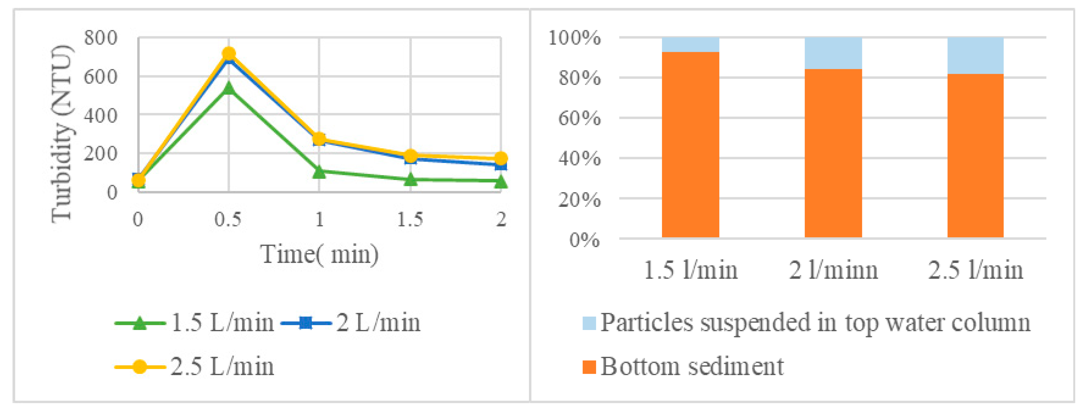
3.3. Effect of Flow Rate

Suspended particles in the water column increased by a factor of greater than two (from 7.41% to 18.13%) with an increase in the flow rate from 1.5 to 2.5 L/min, as shown in the kaolin mass distribution (Figure 6). Greater resuspension of bottom sediment with increased flow rates were also observed by reference [21] for I inlets. As the pipe diameter was not changed, the inflow velocity increased from 1.27 m/s to 1.69 m/s and then 2.12 m/s to maintain continuity. This increase in velocity created higher turbulence, facilitating bottom sediment resuspension. Thus, when designing RWH inlets, the pipe diameter should consider the final flow velocity at the inlet. The tracer study showed no significant difference in RTD. Similar RTD curves were observed at higher flow rates but with higher mean residence times, i.e., 1.58, 1.69, and 1.78 min for inlet a, b, and c, respectively.

3.4. Effect of Outlet Height and Initial Water Level

RTD and cumulative RTD curves obtained for all outlet conditions were almost identical to the graphs shown in Figure 4; thus, significant parameters derived from the RTD are summarized and presented in Table 4. The mean residence time t ¯ increased by more than 25% with increased outlet height. This was likely due to the increased retention capacity of the tank and dead space with higher outlet height. A conservative contaminant such as salt entering the RWH tank would be retained for a longer period of time, enabling it to be diluted or flushed. Thus, a higher outlet height might benefit a multitank system, but might not be beneficial for a single tank RWH system because a large proportion of the stored water in the tank would be inaccessible. The initial water level is an operational parameter that can provide a cushioning effect on incoming water. In this study, changing the initial water level from 0.33 H to 0.75 H led to an almost 40% reduction in the resuspension of bottom sediments; the mass of suspended solids in the top water column decreased from 7.41% to 4.67%.

3.5. Effect of Bottom Sediment

As expected, the initial turbidity level increased with increasing kaolin dosage. However, after an initial rise, the turbidity returned to almost the initial level for all kaolin doses. According to the mass distribution in Figure 7, a larger amount of particulate matter sediment at the bottom of the tank allowed more particulate matter to be resuspended in the water column. Therefore, it is important to maintain the sludge level of the storage tank at a minimum; this can be facilitated by including a drain valve in the tank design and having a proper maintenance schedule.

3.6. Proposed Tank Design/Modifications

Based on the results of this study, the following design/modification recommendations for an RWH harvesting tank are proposed in order to manage the water level of the storage tank more effectively (Figure 8): a J type inlet at 0.1 H, a drain valve at the bottom, and two outlet valves at 0.33 H and 0.5 H. The outlet at 0.5 H could be used during the rainy season or when the water level of the tank is above half capacity. During the dry season or when the water level in the tank is below half the capacity, the outlet at 0.3 H could be used. Reference [21] suggested a conical base for better sediment removal; therefore, the bottom of the tank should be designed according to Figure 8 to improve the flushing of bottom sediment.

4. Conclusions

This study analyzed the inlet and outlet configurations of a typical rainwater harvesting tank in the developing world that affect the water quality of stored water. Installation of a J type inlet resulted in less bottom sediment resuspension and enabled conservative materials to reside within the RWH tank for a longer period than conventional I type inlets, while also releasing the conservative material in low concentrations. This is beneficial for providing users with a higher response time to either isolate the tank from other units of the RWH system or drain the stored water if a conservative pollutant enters the RWH tank. The inlet height had no significant influence on bottom sediment resuspension or RTD; however, a J type inlet placed near the bottom of the tank may allow the initial water height to provide a cushioning effect. The inflow velocity is critical when managing the water quality of stored rainwater. When selecting the pipe diameter, it is recommended to set the inflow velocity below 1.3 m/s to prevent bottom sediment resuspension. However, it is advised to maintain the flow velocity above 0.6 m/s for self-cleaning of the inlet. The outlet height is significant for retaining conservative materials because the retention capacity of the tank is proportional to the outlet height. However, a higher outlet height might not be cost effective for a single tank RWH system; hence, two outlets could be provided as suggested. For a multitank RWH system, a higher outlet height in the first tank can provide a multitude of benefits. If rainwater storage tanks can be properly maintained by regulating the water level in the tank at half-filled conditions using the two outlet system and by regularly draining the bottom sediment, the quality of stored water can be significantly improved at a lower cost. This research did not investigate the influence of bottom sediment on the removal of other contaminants, and whether desludging could assist the removal of other contaminants from RWH tank, which needs to be investigated. Further, the effect of inlet/outlet configuration in multitank RWH systems that are currently gaining popularity needs to be investigated in the future.

Author Contributions

Conceptualization, J.D. and M.H.; methodology, J.D. and M.H.; software, J.D.; validation, J.D. and M.H.; formal analysis, J.D.; investigation, J.D.; resources, M.H.; data curation, J.D. and M.H.; writing—original draft preparation, J.D.; writing—review and editing, M.H.; supervision, M.H.; project administration, M.H.; funding acquisition, M.H. All authors have read and agreed to the published version of the manuscript.

Funding

This research was funded by Science and Technology Support Program through the National Research Foundation of Korea (NRF) funded by the Ministry of Science and ICT(MSIT) (grant number: NRF-2018K1A3A9A04000025).

Acknowledgments

Authors would like to thank the members of Institute of Construction and Environmental Engineering (ICEE) at Seoul National University for their advice and support throughout this research.

Conflicts of Interest

The authors declare no conflict of interest. The funders had no role in the design of the study; in the collection, analyses, or interpretation of data; in the writing of the manuscript, or in the decision to publish the results.

References

  1. WHO/UNICEF. Joint Monitoring Programme (JMP) Report; WHO: Geneva, Switzerland; UNICEF: New York, NY, USA, 2014. [Google Scholar]
  2. UNICEF. Committing to Child Survival: A Promise Renewed—Progress Report; UNICEF: New York, NY, USA, 2014. [Google Scholar]
  3. Won, Y.; Han, M.; Park, H.; Kim, M. Optimal rainwater tank design for control of particulate contaminants. Water Sci. Tech.-Water Sup. 2019, 19, 574–579. [Google Scholar] [CrossRef]
  4. Coombes, P.J.; Kuczera, G.; Kalma, J.D.; Argue, J.R. An evaluation of the benefits of source control measures at the regional scale. Urb. Water 2002, 4, 307–320. [Google Scholar] [CrossRef]
  5. Coombes, P.J.; Kuczera, G.; Kalma, J.D.; Dunstan, R.H. Rainwater quality from roofs, tanks and hot water systems at Figtree Place. In Proceedings of the 3rd International Hydrology and Water Resource Symposium, Perth, Australia, 20–23 November 2000; pp. 1042–1047. [Google Scholar]
  6. Campisano, A.; Butler, D.; Ward, S.; Burns, M.J.; Friedler, E.; DeBusk, K.; Fisher-Jeffes, L.N.; Ghisi, E.; Rahman, A.; Furumai, H.; et al. Urban rainwater harvesting systems: Research, implementation and future perspectives. Water Res. 2017, 121, 195–209. [Google Scholar] [CrossRef] [PubMed]
  7. Simmons, G.; Hope, V.; Lewis, G.; Whitmore, J.; Wanzhen, G. Contamination of potable roof collected rainwater in Auckland, New Zealand. Water Res. 2001, 35, 1518–1524. [Google Scholar] [CrossRef]
  8. Sanchez, A.S.; Cohim, E.; Kalid, R.A. A review on physiochemical and microbiological contamination of roof-harvested rainwater in urban areas. Sustain. Water Qual. Ecol. 2015, 6, 119–137. [Google Scholar] [CrossRef]
  9. Han, M.Y.; Saleh, H.I.; Lee, I.Y.; Kim, Y.J. Characterization of harvested rainwater quality from Seoul city-Korea. In Proceedings of the 8th International Water Technology Conference, Alexandria, Egypt, 26–28 March 2004. [Google Scholar]
  10. Lee, J.Y.; Bak, G.; Han, M. Quality of roof-harvested rainwater—Comparison of different roofing materials. Environ. Pollut. 2012, 162, 422–429. [Google Scholar] [CrossRef] [PubMed]
  11. Spinks, A.T.; Coombes, P.; Dunstan, R.H.; Kuczera, G. Water quality treatment processes in domestic rainwater harvesting systems. In Proceedings of the 28th International Hydrology and Water Resources Symposium: About Water, Barton, ACT, Australia, 1 January 2003; Boyd, M.J., Ball, J.E., Babister, M.K., Green, J., Eds.; Institution of Engineers: Kolkata, India; pp. 2227–2234, ISBN 0858240602. [Google Scholar]
  12. Van Metre, P.C.; Mahler, B.J. The contribution of particles washed from rooftops to contaminant loading to urban streams. Chemosphere 2003, 52, 1727–1742. [Google Scholar] [CrossRef]
  13. Thomas, T. The limitations of roofwater harvesting in developing countries. Waterlines 2014, 33, 139–145. [Google Scholar] [CrossRef]
  14. Egodawatta, P.; Thomas, E.; Goonetilleke, A. Understanding the physical processes of pollutant build-up and wash-off on roof surfaces. Sci. Total Environ. 2009, 407, 1834–1841. [Google Scholar] [CrossRef] [PubMed] [Green Version]
  15. Spinks, A.; Berghout, B.; Dunstan, R.; Coombes, P.; Kuczera, G. Tank sludge as a sink for bacterial and heavy metal contaminants and its capacity for settlement, re-suspension and flocculation enhancement. In Proceedings of the 12th International Rainwater Catchment Systems Association Conference, New Delhi, India, 15–18 November 2005. [Google Scholar]
  16. Scott, R.; Waller, D. water quality analysis of a rainwater cistern system in Nova Scotia, Canada. In Proceedings of the 3rd International Rainwater Collection System Association Conference. Section F: Water Quality, Khon Kaen, Thailand, 14–16 January 1987; pp. 1–16. [Google Scholar]
  17. Master Plumbers and Mechanical Services Association of Australia. Rainwater Tank Design and Installation Handbook; Standards Australia: Sydney, NSW, Australia, 2008. [Google Scholar]
  18. Novak, C.A.; Van Giesen, E.; DeBusk, K.M. Designing Rainwater Harvesting Systems: Integrating Rainwater into Building Systems, Reprint; John Wiley & Sons, Inc.: Hoboken, NJ, USA, 2014; ISBN 978-1-118-41047-9. [Google Scholar]
  19. Haq, S.A. Harvesting Rainwater from Buildings, Reprint; Springer International Publishing: Berlin, Germany, 2018; ISBN 978-3-319-46362-9. [Google Scholar]
  20. Younos, T.; Parece, T.E. Sustainable Water Management in Urban Environments, the Handbook of Environmental Chemistry; Springer: Berlin, Germany, 2016; Volume 47, pp. 209–231. ISBN 978-3-319-29337-0. [Google Scholar]
  21. Magyar, M.; Ladson, T.; Mitchell, V.; Diaper, C. The effect of rainwater tank design on outlet water quality. Aust. J. Water Res. 2011, 15, 71–84. [Google Scholar]
  22. Amos, C.; Rahman, A.; Gathenya, J. Economic analysis and feasibility of rainwater harvesting systems in urban and peri-urban environments: A review of the global situation with a special focus on Australia and Kenya. Water 2016, 8, 149. [Google Scholar] [CrossRef]
  23. Kahinda, J.M.; Taigbenu, A.E. Rainwater harvesting in South Africa: Challenges and opportunities. Phys. Chem. Earth Parts A/B/C 2011, 36, 968–976. [Google Scholar] [CrossRef]
  24. Pe Plus- Products- Water Tanks. Available online: http://www.peplus.lk/products/watertanks.html (accessed on 29 May 2020).
  25. Housing and Building Research Institute. Bangladesh National Building Code; Housing and Building Research Institute: Dhaka, Bangladesh, 2011.
  26. Daejung Chemicals & Metals, South Korea. Available online: http://www.daejungchem.co.kr/main/main.asp (accessed on 7 November 2019).
  27. Ministry of Land, Infrastructure and Transport. Korea Precipitation Frequency Data; Ministry of Land, Infrastructure and Transport: Sejong, Korea, 2016. [Google Scholar]
  28. Benjamin, M.; Lawler, M.; Desmond, F. Continuous Flow Reactors: Hydraulic Characteristics. In Water Quality Engineering: Physical/Chemical Treatment Processes, 1st ed.; John Wiley & Sons, Inc.: Hoboken, NJ, USA, 2013; pp. 29–70. ISBN 978-1-118-16965-0. [Google Scholar]
  29. Maus, C.; Uhl, M. Tracer studies for the modelling of sedimentation tanks. In Proceedings of the Seventh International Conference on Sustainable Techniques and Strategies in Urban Water Management, Lyon, France, 27 June–1 July 2010; GRAIE: Lyon, France, 2010. [Google Scholar]
  30. Werner, T.M.; Kadlec, R.H. Application of residence time distributions to stormwater treatment systems. Ecol. Eng. 1996, 7, 213–234. [Google Scholar] [CrossRef]
Figure 1. (a) Typical rainwater harvesting system (RWH), (b) typical inlet/outlet configurations in a storage tank, and (c) RWH system with a calmed inlet proposed by reference [3].
Water 12 01970 g001
Figure 2. Inlet types considered (a, I type; b, L type; c, J type) in the particle and tracer experiments (left) and experimental set up (right). NaCl was added for the tracer test and kaolin clay bottom sediment was present only for the particle resuspension experiment.
Water 12 01970 g002
Figure 3. Turbidity variations and distribution of kaolin mass according to inlet type.
Water 12 01970 g003
Figure 4. Residence time distribution (RTD) and cumulative RTD for three inlet types (inflow rate 1.5 L/min, inlet at 0.25 H, outlet at 0.33 H).
Water 12 01970 g004
Figure 5. Turbidity variation and distribution of kaolin mass with inlet height (J type inlet).
Water 12 01970 g005
Figure 6. Turbidity variation and distribution of kaolin mass with inflow rate (J type inlet).
Water 12 01970 g006
Figure 7. Turbidity variation and kaolin mass distribution for different doses of kaolin clay (J type inlet).
Water 12 01970 g007
Figure 8. Recommended inlet/outlet design for rainwater storage tanks (left) and drain valve design for improved bottom sediment removal (right).
Water 12 01970 g008
Table 1. Specifications of the sediment resuspension experiments and tracer study experiments.
ExperimentParameter InvestigatedInlet TypeInlet Height/H Flow Rate (L/min)Initial Water Level/HAmount of Kaolin Settled after 24 h (g) Outlet Height/H
Sediment resuspensionEffect of inlet typeI, L, J0.251.50.3320.33
Effect of inlet heightJ0.1, 0.25, 0.51.50.3320.33
Effect of flow rateJ0.251.5, 2, 2.5 0.3320.33
Effect of initial water heightJ0.251.50.33, 0.5, 0.7520.33
Effect of amount of bottom sedimentJ0.251.5 0.330.5, 1, 20.33
Tracer testEffect of inlet typeI, L, J0.251.50.33-0.33
Effect of inlet heightJ0.1, 0.25, 0.51.50.33-0.33
Effect of flow rateJ0.251.5, 2.20.33-0.33
Effect of outlet heightJ0.251.5 0.33-0.33, 0.6
Table 2. Example residence time distribution (RTD) calculations using the method described in Section 2.2 (inlet at 0.25 H, outlet at 0.33 H, flow rate of 2.2 L/min, I type inlet).
Time (min)Conductivity (µS/cm)Concentration (mg/L)ΔtiCkθEtF
0.251146.0453.450.25457.980.150.670.10
0.501149.0454.950.25454.200.310.670.21
0.751129.0444.950.25449.950.470.660.32
1.001095.0427.950.25436.450.630.630.42
1.25988.4374.650.25401.300.780.550.51
1.50908.0334.450.25354.550.940.490.60
1.75804.3282.600.25308.521.100.420.67
2.0702.0231.450.25257.021.260.340.73
2.25624.9192.900.25212.171.420.280.78
2.50556.8158.850.25175.881.580.240.83
2.75498.9129.900.25144.381.740.190.86
3.00446.3103.600.25166.751.890.150.89
3.25408.084.450.2594.032.050.130.91
3.50373.167.000.2575.732.210.100.93
3.75348.454.650.2560.832.370.080.94
4.00327.344.100.2549.382.530.070.95
4.25309.535.200.2539.652.680.050.96
4.50295.628.250.2531.722.840.040.97
4.75284.522.700.2525.483.000.030.98
5.00274.617.750.2520.223.160.030.98
Table 3. Mean residence time, variance of RTD, and mass recovery for all types of inlet.
Inlet Type t ¯ σ2 (min2)Mass Recovery %θ at 95% Mass Recovery
I2.452.4999.132.52
L2.532.9297.852.59
J2.893.5193.092.64
Table 4. Mean residence time and variance of RTD for different outlet heights (J type inlet).
Outlet Height t ¯ σ2 (min2)
0.33 H1.92.51
0.6 H2.44.92

