Article

Numerical Study of the Interaction between a Collapsing Bubble and a Movable Particle in a Free Field

College of Metrology and Measurement Engineering, China Jiliang University, Hangzhou 310018, China
*
Authors to whom correspondence should be addressed.
Water 2020, 12(12), 3331; https://doi.org/10.3390/w12123331
Submission received: 15 September 2020 / Revised: 17 November 2020 / Accepted: 23 November 2020 / Published: 27 November 2020
(This article belongs to the Special Issue Numerical Modeling and Simulation of Multi-Phase Flows)

Abstract

:
This study numerically investigates the interactions between a collapsing bubble and a movable particle with a comparable size in a free field, which is associated with the microscopic mechanisms of the synergetic effects of cavitation erosion and particle abrasion on the damages of materials in fluid machineries. A new solver on OpenFOAM based on direct numerical simulations with the volume of fluid (VOF) method capturing the interface of a bubble and with the overset grid method handling the motion of the particle was developed to achieve the fluid–structure interaction (FSI). The results show that bubbles in cases with stand-off parameter χ (defined as ( d 0 R p ) / R 0 ), where d 0 is the initial distance between the centers of the bubble and particle, and R p , R 0 are the particle’s radius and the initial radius of the bubble respectively >1, experience spherical-shaped collapse under the influence of the approaching particle, which is attracted by the collapsing bubble. The bubbles in these cases no longer present non-spherical collapse. Additionally, a force balance model to account for the particle dynamics was established, in which the particle velocity inversely depends on the size of the particle, and approximately on the second power of the initial distance from the bubble. This analytical result accords with the numerical results and is valid for cases with χ > 1 only, since it is based on the theory of spherical bubbles. These conclusions are important for further study of the interactions between a bubble and a movable particle near a rigid wall.

1. Introduction

The synergetic effect of cavitation erosion and particle abrasion is one of the common and serious issues of hydraulic structures and machinery [1,2,3] in silt-laden waters. Cavitation bubbles form due to sufficiently low pressure in liquid and immediately collapse passing high-pressure areas of flow [4,5]. The micro-jets and pressure waves emitted during the collapse stage may damage the surfaces of hydraulic structures and machinery in contact with the liquid [6]. Particle abrasion is caused by the impact of particles on these surfaces, which causes deformation or loss of material [7]. Generally, a much greater erosion rate emerges when cavitation occurs in slit-laden waters. The erosion rate is even greater than the sum of both cavitation erosion and particle abrasion considered separately [8,9,10,11,12,13]. The interaction between cavitation bubbles and particles is more than likely the primary cause. Therefore, the study of the interaction between cavitation bubbles and particles is crucial to understanding the synergistic effect of cavitation and particles and then avoiding or enhancing the effect. In fact, the coexistence of cavitation bubbles and solid particles is also found in other scenarios, e.g., ultrasonic cleaning [14], kidney stone fragmentation [15], drug delivery by ultrasonic cavitation [16] and mineral processing [17,18].
Since the 1990s, plenty of studies have investigated the synergistic effect of cavitation and solid particle erosion focusing on the macroscopic studies, e.g., the damage was evaluated by number [19], depth [11] and diameter of pits, mass loss [19,20,21], erosion rate [21,22], morphologies [11,20,23] and roughness [19,21] of the material surface observed under the scanning electron microscope (SEM), surface residual stress [21] and efficiency change [24]. In order to shed light on the underlying synergetic mechanisms, the micromechanism, in terms of the interactions between cavitation bubbles and particles, is being intensively investigated. The interactions between cavitation bubbles and particles include effects of particles on the cavitation inception and the bubble–particle interaction dedicated to the bubbles’ dynamics during their growth and collapse influenced by the particles [8]. This study is concerned with the latter interaction.
A number of experimental studies have been dedicated to the interaction between cavitation bubbles and particles in suspension [25]. The previous work generally falls into two categories: the particle motion induced by the growth and collapse of cavitation bubble; the changed bubble dynamics by the influence of the particle.
For the particle motion induced by the bubble dynamic, the particles in most experimental setups are controlled using a flexible thread or a thin steel rod. Soh et al. [26] used an electric spark to generate large bubbles (∼15 mm in maximum radius) in the vicinity of polyethylene particles (2 mm in radius), which were hanging from strings or resting on the boundary wall. The suspended particles were not apparently affected because they were rather far away from the site of bubble formation and restricted by cords. Ohl et al. [27] employed a spark bubble to move the suspended particle as the bubble collapsed. The particle has a radius of 1.50 mm, and the maximum bubble radius is about 4 mm. The study showed that the movement of a particle next to a cavitation bubble is dependent on the stand-off distance between the two. The particles that are close to the bubble are pushed away from the bubble after its collapse while the particles that are a bit further from the bubble move towards the bubble after its collapse. Meanwhile there was a brief description of the collapsing form of the bubble. Poulain et al. [28] proposed an experimental study to characterize the effect of a spark-induced cavitation bubble on a tethered spherical particle with similar size about 2 mm in relatively large stand-off distances. With this experimental setup, the particle is pushed away when the bubble grows while it is attracted to the bubble when the bubble collapses. They also developed an analytical model for the particle behavior after the disappearance of the bubble showing that the particle velocity inversely depends on the density and size of the particle, and approximately on the fourth power of the initial distance from the bubble. Wu et al. [29] reported an investigation to further understand the mechanism of motion of a free-settling spherical particle driven by a laser-induced bubble, with fewer restrictions and smaller disturbances to the motions of the particle and the cavitation bubble than in the studies above. The maximum radius of the cavitation bubble is about 2 mm while the size of particles (0.1–0.5 mm in radius) is much smaller than the bubbles. The free-settling particle can be rapidly accelerated because of the growth of the nearby bubble.
For the changed bubble dynamics by the influence of the particle, the particles in most experimental setups are controlled stationary. Xu et al. [21] researched the mechanism of the collapse of cavitation bubbles (2–4 mm in maximum radius) in a free field when particle of different sizes (1–5 mm in radius) exist at different distances. The impact on the collapse characteristics of the cavitation bubble of particles was studied by changing the cavitation bubble size, particle size, and stand-off distances between the bubble and the particle. They found under a specific condition, particles protect the wall by changing the direction of the collapse of the cavitation bubble or by absorbing it. Zhang et al. [30] designed an experimental system to investigate the influence of the spherical particle on the laser-induced cavitation bubble dynamics with a focus on the collapsing process and the generation of micro-jet. A wide range of parameter zone, including the bubble maximum radius (0.5–1.3 mm), the particle radius (0.5–1.5 mm) and the stand-off distance between the two, was investigated in detail. Three cases (mushroom-shaped, pear-shaped and spherical-shaped collapses) are identified based on the collapsing process of the cavitation bubble.
The bubble and particle dynamics are related with the surrounding flow field and pressure distribution. Since the life cycle of a cavitation bubble is extremely short and the size of bubble and particle is extremely small, research on the distribution of flow fields, pressure changes, temperature effects can hardly be tested experimentally [31]. Therefore, researchers use numerical simulations to reveal the mechanisms of the interaction between cavitation bubbles and particles. Teran et al. [32] performed a two-dimensional simulation to study the behavior of the particles (∼0.07 mm in radius) that interacted with a cavitation bubble with much larger size (∼2.5 mm in maximum radius) collapsed near a solid surface. This analysis laid special stress on the effect of the bubble dynamics on particles. The particle size, density and position of the particle with respect to the bubble interface strongly affected the maximum velocity of the particles. The experimental results and a simplified analytical study validated the numerical simulations. Li et. al. [33] employed boundary integral method (BIM) together with the auxiliary function to simulate the coupling process between a large gas bubble (18–33 mm in maximum radius) and a movable sphere with a comparable size (40 mm in radius) in a free field. The effects of some dimensionless parameters, the stand-off distance and the size ratio, on bubble dynamics and sphere motion were analyzed. The pressure contours and the velocity fields of the flow are also provided for better analysis of the nonlinear coupling effect between bubble and sphere.
These simulations fully harnessed its own advantage to give more information about the surrounding flow field, which could help reveal the micromechanism of the interaction between bubbles and particles. However, the involved scales of bubble and particle (with the order of centimeters) were rather large that correspond to the applications in engineering such as underwater explosion, but that are not generally the case in silt-laden rivers. The fluid viscosity was also ignored because the large Reynolds number related with the relatively large size of bubble and sphere. The fluid was further assumed incompressible and the flow was irrotational. In certain conditions, a thin liquid layer forms between the bubble and sphere during the expansion phase, and the importance of the viscosity in this process should be further investigated. During the last stage of bubble collapse, the fluid is compressible which makes the assumption of incompressible fluid no longer valid. Meanwhile the axisymmetric configuration was adopted in the simulation, and the sphere motion is constrained in one-dimensional in the z-axis direction. Three dimensional simulations of the interaction between a cavitation bubble and a solid particle with a comparable size in the millimeter or micrometer scale considering fluid viscosity and compressibility are needed for exploring more flow physics in 3D configurations to make the physical mechanism clearer.
In the present work, the interactions between a collapsing vapour bubble and a movable spherical particle with a comparable size of a few millimetre in a free field are numerically investigated. The present study mainly focuses on the changed collapsing form of the bubble influenced by the particle, and the particle motion induced by the collapse of the bubble. A range of parameter zone (e.g., in terms of the bubble size, the particle size and the initial distance between the bubble and the particle) is researched. Furthermore, we develop an analytical model of force balance for the dynamics of the particle near the bubble to predict the maximum particle velocity. The sections of the present paper are organized as follows. Section 2 introduces a new developed CFD solver for our flow problem. Section 3 compares some representative cases having quite different features with corresponding experimental results to validate the solver. Section 4 applied the solver to our flow problem and a general picture of the bubble–particle interactions is shown with a typical case introduced in detail. The collapsing forms of cavitation bubbles influenced by the particles are presented and the dynamics of particles are described with an analytical model. Section 5 summarizes the major findings of present work and makes suggestions for future research.

2. Numerical Modeling

In the present study, the bubble is assumed to be initiated at a distance d 0 beside the initially quiescent spherical particle, as shown in Figure 1a.The direct numerical simulation based on the VOF method capturing the interface of bubble is adopted to simulate the collapsing process of the bubble, and overset grid method is used to handle the six degrees of freedom (6-DOF) motion of the particle. To enable this fluid–structure interaction (FSI), a CFD solver named overCompressibleInterDyMFoam is developed based on two solvers on OpenFOAM v1906, overInterDyMFoam and modified compressibleInterDyMFoam.
Within the scope of the VOF approach, the liquid–vapor two-phase flow is treated as a homogeneous mixture considering the viscosity, surface tension and compressibility of the fluid and hence only one set of the continuity and the momentum equations is described as follows:
ρ t + · ( ρ U ) = 0 ,
ρ U t + · ( ρ U U ) = p + 2 · ( μ D ) 2 3 ( μ · U ) + σ κ n ,
in which t is the time, U is the mixture velocity, p its pressure, D = [ U + ( U ) T ] / 2 is the deformation tensor, σ is the surface tension coefficient, κ is the mean curvature of the interface, n is the unit normal vector of the interface. The mixture density ρ and viscosity μ are assumed to vary linearly with the volume fraction α of each phase:
ρ = α 1 ρ 1 + α 2 ρ 2 ,
μ = α 1 μ 1 + α 2 μ 2 ,
in which the subscripts 1 and 2 stand for the properties of liquid and vapor respectively and α 1 + α 2 = 1 for a binary mixture. Since the mixture is considered as a compressible medium, the equation of state (EOS) of each phase should be supplied. However, the thermal physics of vapor bubble is still not fully understood due to the contribution from laten heat, and the Rayleigh–Plesset equation [34] supposes that the pressure inside the vapor bubble can be kept constant when modeling its collapse. Therefore, the pressure and density within the vapors are set to be constant. The EOS for the liquid phase is:
ρ 1 = ρ 10 + 1 c 1 2 p ,
in which the subscript 0 represents the initial state, and c 1 is the speed of sound in liquid. ρ 10 = 998 kg/m 3 and c 1 = 1500 m/s are set here. In addition, the VOF method requires a transport equation describing the spatial and temporal variation of α to close the equations of motion:
( α 1 ρ 1 ) t + · ( α 1 ρ 1 U ) = 0 .
To model the interaction between the particle and the fluid, the sixDoFRigidBodyMotion solver on OpenFOAM coupled with an overset mesh was used, which enabled us to calculate the flow forces and moments of the particle with 6-DOF immersed in a fluid. The flow forces F comprise normal pressure:
F p = i ρ i s f , i ( p i p r e f ) ,
and tangential viscous contributions:
F ν = i s f , i · ( μ R dev ) ,
in which s f , i is the face area vector of the elements at boundaries and R dev the deviator stress tensor. The flow forces exerted to solid particles are calculated through the velocity and pressure field obtained in the simulation of vapor–liquid two-phase flow. Moments are caused by the flow forces:
M = i ( r f , i r 0 ) × ( ρ i s f , i ( p i p r e f ) ) + i ( r f , i r 0 ) × ( s f , i · ( μ R dev ) ) ,
in which r f , i is the position vector of cell center at boundaries and r 0 the position vector of rotational center. The acceleration a and the angular acceleration ε are related to the forces and moments as
F = m a ,
M = ε I ,
in which m denotes the mass and I denotes the moments of inertia. The velocity and angular velocity of the particle are obtained by integrating the translational and angular acceleration over the time step, further the distance traveled and angle rotated of particle are available. However, the exaggerated body motion amplitude challenges the commonly applied mesh morphing method in CFD, due to the resulting mesh distortion and subsequent numerical instability. The overset method adopted here consists of a fixed background mesh and a dynamic overset mesh attached to the particle (Figure 1b) which is subject to large displacements. The different meshes may arbitrarily overlay each other and they are internally static, thereby retaining their original structure and quality, but are allowed to move relative each other. In order to couple the disconnected mesh regions, the flow variables are interpolated between the meshes. Therefore, this method can inherently handle large amplitude motion in one or more DOF with the mesh structure and quality remaining constant throughout the simulation at the expense of higher computational costs.
Finite volume method is applied to discretize the equations on OpenFOAM. Second-order Euler implicit differencing is applied to the time derivatives. The spatial differencing of the convective terms uses the flux-difference splitting scheme based on van Leer’s MUSCL method. A second-order central differencing is used for the viscous terms. The time step is set small enough to ensure a maximum Courant number of less than 0.3 everywhere in the computational domain. The pressure-velocity coupling is handled via the PISO algorithm.

3. Validation

3.1. Vapor–Liquid Two-Phase Flow

3.1.1. The Collapse of a Vapor Bubble in a Free Flow Field

The first study serves as a verification study of the vapor–liquid two-phase flow and concerns the collapse of a vapor bubble in a free field (Figure 2a). The module about overset grid method is turned off first in the solver. The simulation setup are as follows. The bubble with an initial radius R 0 = 1 mm is placed at the center of the static flow field with its size 50 mm × 50 mm × 50 mm. The grid of this whole computational domain is orthogonal and refined within a cubic with a size of 10 mm 3 that is in the middle of the domain and large enough to contain the bubble (Figure 2b). In order to provide appropriate mesh resolution inside the bubble to capture the interface of vapor–liquid two-phase flow, four different resolutions, i.e., 30, 40, 45 and 50 cells in the radial direction inside the bubble, were created to inspect the spatial resolution requirement for numerical analysis. The flow field is static at initial time. At the far field boundaries, the velocity field is constrained by the zero gradient boundary condition while a fixed pressure of p = 1 bar is imposed. The zero gradient boundary condition is further applied to the liquid volume fraction field at all boundaries. The pressure field is initialized at p v = 3540 Pa inside the bubble and p = 1 bar outside the bubble in the liquid. To verify the numerical model the time variations of the bubble radius R b ( t ) are compared with the analytical solution of the evolution of a spherical bubble for the simplified Rayleigh–Plesset equation [34]. Figure 2c shows the temporal evolution of bubble radius obtained from the above-mentioned mesh resolutions and analytical solution respectively, in which the bubble radius R b and time t are nondimensionalized as
R * = R b / R 0 ,
T * = t / t c ,
where t c is the time span of bubble collapse obtained from the analytical solution, with the formula
t c 0.921 R 0 ρ 1 p p v .
The results from all mesh resolutions fit the analytical solution very well at the initial stage of collapse, but when entering the final stage of collapse some differences appear between numerical and analytical results. Figure 2d shows the L2 norm for error of bubble radius indicating a second-order accuracy. The error is defined as R e r r o r = | R c o m p . R a n a l y . | / R 0 , in which R c o m p . and R a n a l y . are bubble radii from computational and analytical solutions respectively. The root mean squared error (RMSE) of cases 1–4 are 0.03394, 0.01761, 0.01357 and 0.02274 respectively, so 45 grids in the radial direction was chosen to provide grid-converged solutions.

3.1.2. The Collapse of a Vapor Bubble near a Rigid Wall

In order to demonstrate that the present numerical model can apply to general 3D problems, and is not limited to spherical problems, we consider its verification with a bubble collapsing near a rigid wall (Figure 3a) when the collapse of the bubble presents non-spherical collapse. First, γ = L / R 0 is introduced to present the non-dimensional initial distance between the bubble and the wall. A case with γ = 1.1 which refers to Kling’s experimental research [35] is considered to inspect the profile of the collapsing bubble. Their experiments were conducted in a high-speed closed-loop water tunnel. Static pressure throughout the test section was about 2 atm. The maximum radius of spark-induced bubbles is 2 mm and some selected frames from bubble collapse sequences are given. In our simulation, the setup of boundary conditions is the same as the case in Section 3.1.1, except that a fixed pressure of p = 2 atm is imposed at the far field boundaries and a zero gradient boundary condition of the pressure field is set at the rigid wall only. A vapor bubble with an initial radius R 0 = 2 mm is placed 2.2 mm away from the wall. In the liquid, the pressure field is initialized at p = 2 atm. Figure 4 compares the profiles of the collapsing bubble at several representative time steps between experimental and numerical results, which show good agreement with each other. The bubbles both collapse towards the wall, and present ellipsoidal collapse at the early stage and then heart-shaped collapse at the last stage. Further, as we know, the collapse time T c for the case of a bubble near a wall is longer than that in the symmetric case, i.e., the wall effect [36]. Rattray’s equation [36] reflects this effect:
T c = t c ( 1 + 0.205 1 γ ) .
In Table 1, specifications of the distances between the bubble and the wall in different cases are presented. The setup of boundary conditions and flow field is the same as the case with γ = 1.1 above. The collapse times obtained from these cases agree well with those computed by Equation (15) (Figure 3b), and the RMSE between numerical and analytical results is 0.00422. On the whole, the numerical model can apply to general 3D vapor–liquid two-phase flow.

3.2. Assessment of the Overset Grid Method

This study serves as a verification study of the overset grid method, and concerns the interaction between a collapsing vapor bubble and a particle in free flow field (Figure 1). The module about overset grid method has been turned on in the solver and the overset grid is applied to the moving particle. The cases to be considered refer to Xu et al.’s experimental research [21]. Their experimental system includes a high voltage pulse bubble generation system which can generate a cavitation bubble in a glass container with a temperature of 20 C and atmosphere pressure of 1 bar. The sizes of the cavitation bubbles can be regulated. In Table 2, specifications of the initial radius of the bubble R 0 , particle radius R p and the initial distance between their centers d 0 in different cases are presented. The simulation setup of the background flow is the same as the case in Section 3.1.1. The outer boundary of the overset grid is set as a designated type “overset”, and the zero gradient boundary condition is applied to all fields at the particle wall. The density of particle and liquid is set to be identical to achieve the suspension of particle in liquid, while particles are attached to thin steel rods or flexible threads in experiments. To compare with the experimental results, the particle with overset grid is static. A stand-off parameter is defined as follows [37]:
χ = ( d 0 R p ) / R 0 .
Figure 5, Figure 6 and Figure 7 compare the profiles of the collapsing bubble at several representative time steps between experimental and numerical results. For the cases with small value of χ , nearly spherical-shaped bubbles are demonstrated. With the size of bubble increasing, for the cases with medium value of χ , an oval-shaped bubble is shown and collapsed towards the particle. For the cases with large value of χ , the bubble is no longer a spherical shape at initial time since the left half of the particle is engulfed by it. The profile of collapsing bubble is similar to that a bubble collapsed near a wall. As a whole, the profiles of collapsing bubble in simulations are in good agreement with those in experiments, which verifies the overset mesh method.

4. Results and Discussion

In this section, to study the interaction between a collapsing vapor bubble and a particle in a free flow field (Figure 1), cases in Table 2 are concerned once again. Only this time, the particle has 6-DOF motions. The setup of boundary conditions is the same as for the cases in Table 2. 
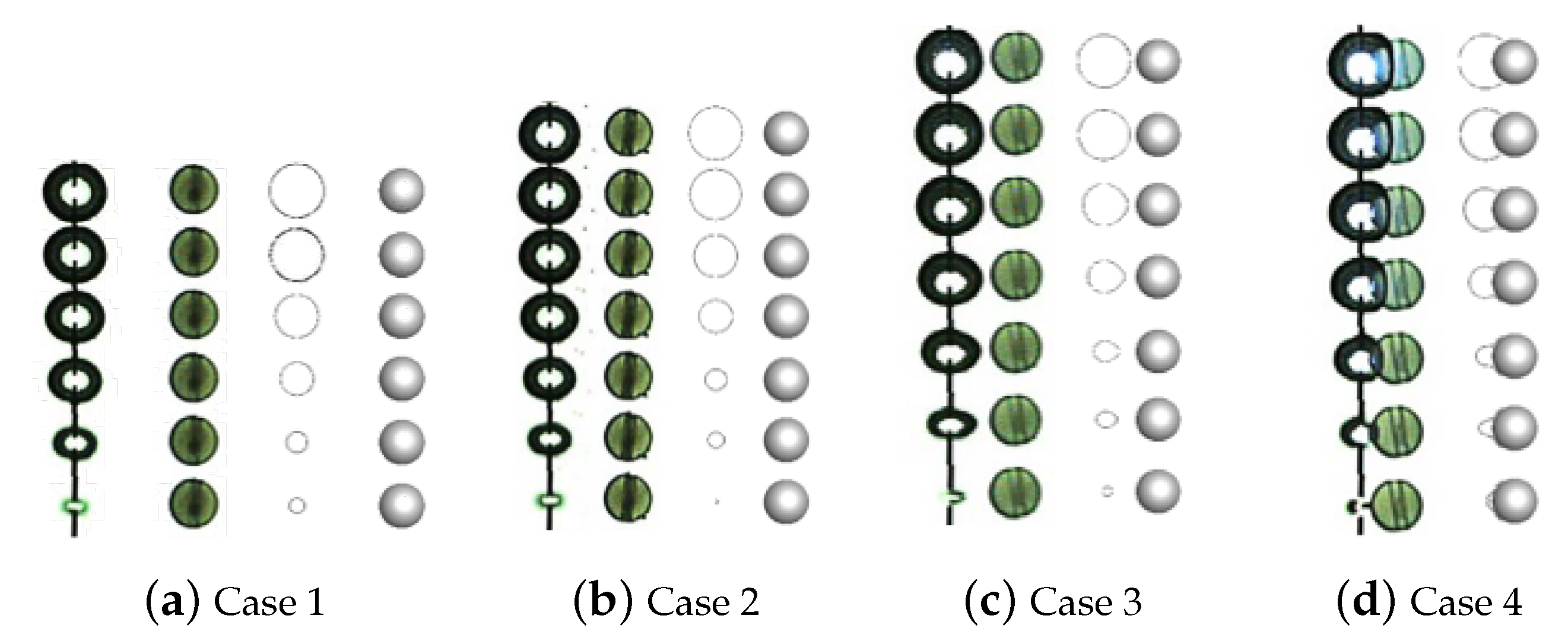
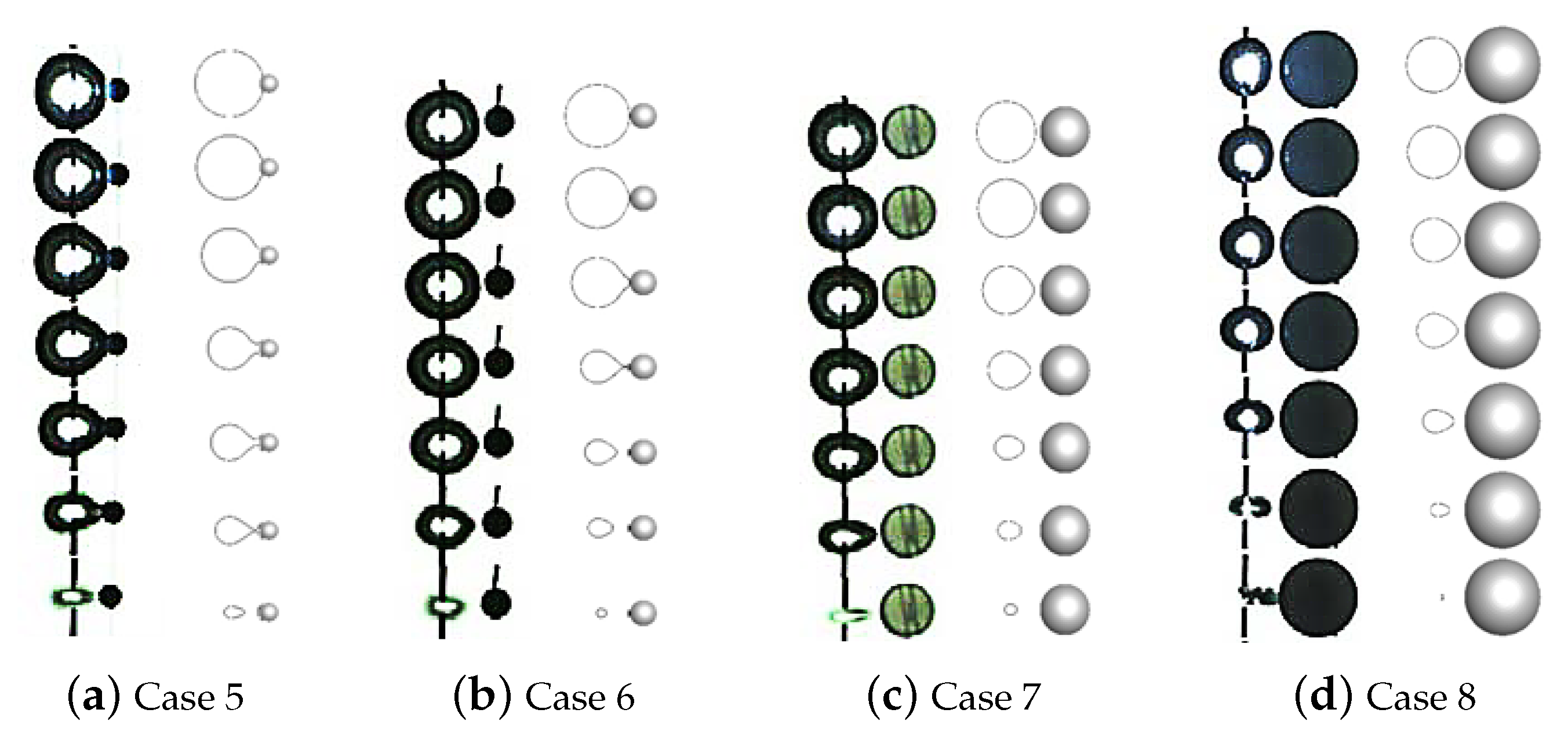
Table 3 represents the profiles of the collapsing bubble at several representative time steps for these cases. Compared to the cases with static particles, besides in the case with an extremely large value of χ 
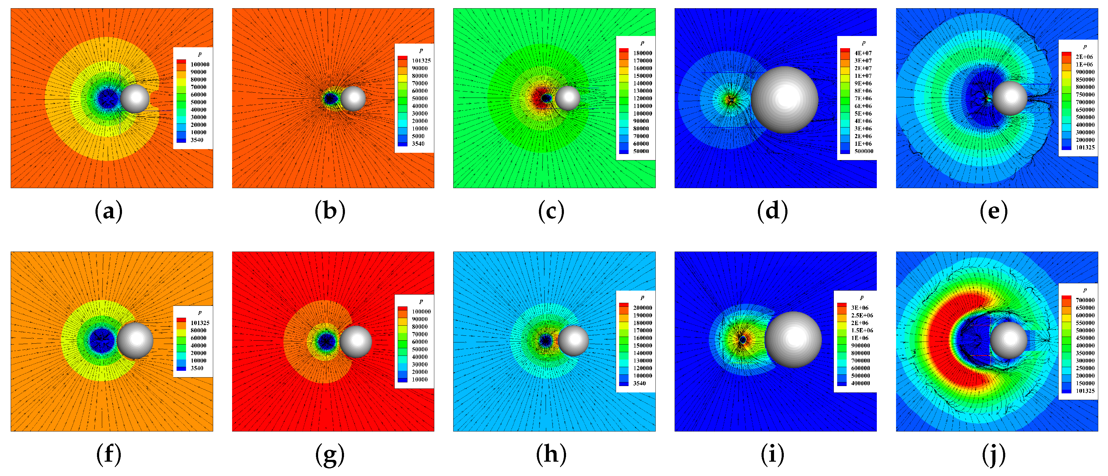
, all bubbles experience a nearly centripetal collapse and no longer collapse towards the particle. To illustrate this difference, the patterns of the streamlines and pressure contours (Figure 8) calculated from case 8 with static particles and movable particles, respectively, are used. Figure 8a–e shows the evolution of flow for the cases with static particle. At the initial time, the pressure inside the bubble is much lower than the ambient pressure, so the bubble starts to collapse, and surrounding water starts to flow towards the bubble to fill the space released by it (Figure 8a). The radial water flow is retarded by the particle which is located to the right of the bubble. A wake region of sphere forms between the bubble and particle, and the pressure on the right of the bubble is less than the pressure on the left of the bubble during the whole collapse phase, so that the bubble becomes elongated towards the particle and the end of the bubble closer to the particle collapses slower due to the lower pressure gradient across the bubble. Therefore, an oval-shaped bubble is formed (Figure 8b,c). The severe pressure is generated inside the bubble, which gives rise to the emission of shock waves at the final stage of collapse (Figure 8d). The water at the collapse center begins to flow outwards, and an interface of tangential velocity only is formed between the inward and outward radial flow. The particle again blocks the outflow, and a wake region is formed on the other side of the particle; therefore, the spherical velocity interface is broken by the wake region (Figure 8e). In a phrase, the bubble presents a non-spherical collapse influenced by the stationary particle. Figure 8f–j shows the evolution of flow for the cases with a movable particle. When the bubble starts to collapse, the inward radial flow drives the particle towards the bubble (Figure 9). The particle no longer blocks the flow to form a low-pressure area, so that the bubbles with χ that are not too large all experience a nearly spherical collapse (Figure 8f–h). The water at the collapse center also flows outwards after collapse and decelerates the particle. The particle cannot keep pace with the flow due to inertia, so it blocks the outflow (Figure 8j).
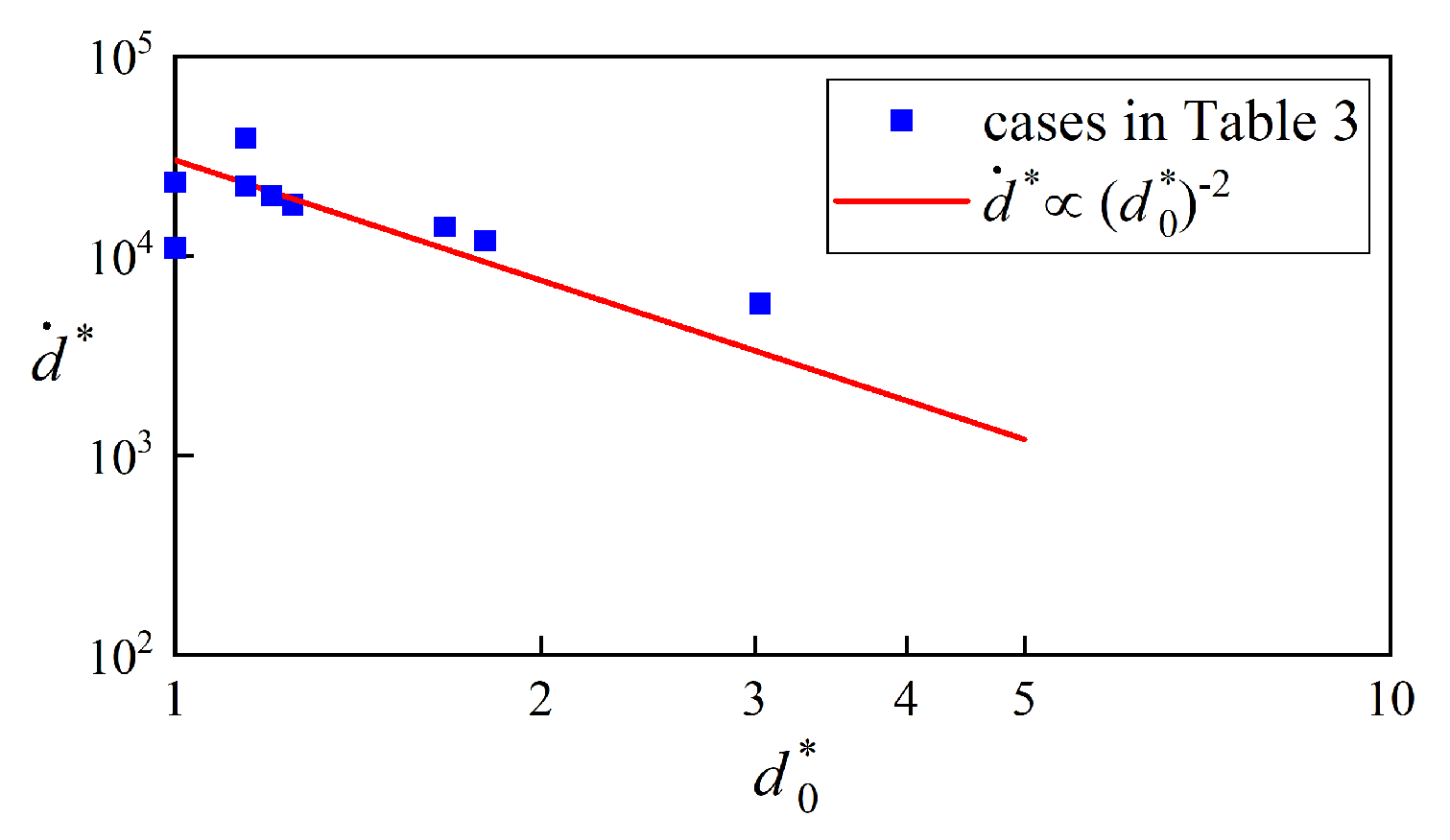
The collapsing forms of bubbles influenced by the moving particle have been illustrated, and what follows are the dynamics of particles induced by the collapsing bubbles. The translational movement of these particles in other directions is negligible compared with that in the direction approaching a collapsing bubble. Figure 9 also shows that the particle moves at a constant speed, which occupies most of the characteristic collapse time. The particle velocity inversely depends on the square, not on the fourth power of the initial distance from the bubble. An analytical theory which is an extension of Poulain et al.’s theory [28] will be developed to evaluate the effects of related parameters, including the sizes of the particle and bubble, R p and R b respectively, and the distance between them. Only the cases χ > 1 are considered. Due to spherical symmetry, the flow velocity u in spherical coordinates u = u e r is given by the mass conservation equation for an incompressible fluid [38]:
u ( r , t ) = ( R b ( t ) r ) 2 R ˙ b ( t ) .
The drag force F d r a g = F d r a g e r acting on the particle is given by
F d r a g ( t ) = s g n ( u ) 1 2 C D ρ 1 A [ u ( d ( t ) , t ) ] 2 ,
in which A = π R p 2 is the projected area of the particle, and C D is the drag coefficient [39]. For the Reynolds number ranges and streamline pattern, and the drag coefficient of this Stokes flow is determined using
C D = 24 Re b ,
in which Re b is the particle Reynolds number based on the its radius and slip velocity, given by Re b = ( ρ 1 2 R p | u u p | ) / μ 1 , where u p is the velocity of particle. The particle Reynolds numbers are about 1 for the cases χ > 1 in this work. The motion of the particle follows the momentum equation
m e f f d ¨ = F d r a g ,
in which m e f f = m p + 1 2 m p is the total mass and the last term accounts for the added mass of particle. The velocity of the particle can be evaluated by integrating this equation of motion over the collapse phase:
d ˙ = 12 μ 1 A m e f f 2 R p d 0 2 0 t c R b 2 R ˙ b dt ,
in which the displacement of the particle from its initial position d 0 during the collapse is neglected in the drag expression, Equation (17), and d ( t ) = d 0 for simplicity, since the maximum displacement d m a x / d 0 0.5 –−8%, as shown in Figure 8. The dimensionless velocity and position are defined as d ˙ * = d ˙ × m e f f / ( μ 1 R p R 0 ) and d 0 * = d 0 / R 0 respectively, leading to the following power-law relation:
d ˙ * ( d 0 * ) 2 .
Figure 10 shows the dimensionless particle velocity as a function of the dimensionless distance between the bubble and the particle for the cases χ > 1 , and it coincides with the Equation (22).

5. Conclusions

In the present work, the interactions between a collapsing cavitation bubble and a movable spherical particle with a comparable size in a free field have been numerically investigated. The dynamics of cavitation bubble, especially the collapsing forms of cavitation influenced by particles and the dynamics of particles induced by collapsing bubbles are the concerns of our paper. A new solver was developed on Openfoam to simulate the interactions between a bubble and a particle. The cases without particles in a free field and near a rigid wall and with stationary particles were all illustrated first for the validation of the solver. Cases considering a range of parameters, including the different scales of bubbles and particles and different distances between them, were researched and compared with the corresponding experimental cases. Some conclusions could be drawn from the results:
  • The collapsing forms of cavitation bubbles in cases with stand-off parameter χ > 1 experience spherical-shaped collapse under the influence of the approaching particle, which is attracted by the collapsing bubble. These bubbles no longer collapse towards particles, which happens in cases with stationary particles.
  • As for the dynamics of particles induced by cavitation bubbles, an analytical model based on force balance shows that the velocity of particle inversely depends on the size and density of the particle, and approximately on the second power of the initial distance from the bubble. It is an extension of Poulain et al.’s theory in low Reynolds number range.
In future work, further numerical studies will be performed to investigate the emission of pressure wave and jet impacts of the cavitation bubble on movable particles. Furthermore, the interaction between a cavitation bubble and a movable particle near a rigid wall will be studied, which will help us understand the interactions between bubbles and particles in macro-scale flow.

Author Contributions

Conceptualization, L.C.; methodology, L.C.; software, L.C., Y.Z. and H.D.; validation, Y.Z.; formal analysis, L.C. and Y.Z.; resources, X.L.; data curation, H.D.; writing—original draft preparation, Y.Z.; writing—review and editing, L.C.; visualization, Y.Z. and H.D.; funding acquisition, X.L. All authors have read and agreed to the published version of the manuscript.

Funding

This research was funded by National Natural Science Foundation of China, grant number 51871206; the National Key Research and Development Programmes of China, grant number 2017YFF0210704; and Zhejiang Provincial Natural Science Foundation, grant number LQ20E090005.

Conflicts of Interest

The authors declare no conflict of interest.

References

  1. Gohil, P.P.; Saini, R.P. Coalesced effect of cavitation and silt erosion in hydro turbines—A review. Renew. Sustain. Energy Rev. 2014, 33, 280–289. [Google Scholar] [CrossRef]
  2. Arndt, R. Some remarks on hydrofoil cavitation. J. Hydrodyn. Ser. B 2012, 24, 305–314. [Google Scholar] [CrossRef]
  3. Escaler, X.; Egusquiza, E.; Farhat, M.; Avellan, F.; Coussirat, M. Detection of cavitation in hydraulic turbines. Mech. Syst. Signal Process. 2006, 20, 983–1007. [Google Scholar] [CrossRef] [Green Version]
  4. Hammitt, F.G. Cavitation and Multiphase Flow Phenomena; McGraw-Hill: New York, NY, USA, 1980. [Google Scholar]
  5. Knapp, R.T.; Daily, J.W. Cavitation; McGraw-Hill: New York, NY, USA, 1970. [Google Scholar]
  6. Dular, M.; Bachert, B.; Stoffel, B.; Širok, B. Relationship between cavitation structures and cavitation damage. Wear 2004, 257, 1176–1184. [Google Scholar] [CrossRef]
  7. Zambrano, O.A.; García, D.S.; Rodríguez, S.A.; Coronado, J.J. The Mild-Severe Wear Transition in Erosion Wear. Tribol. Lett. 2018, 66, 95. [Google Scholar] [CrossRef]
  8. Zhang, Y.; Qian, Z.d.; Ji, B.; Wu, Y. A review of microscopic interactions between cavitation bubbles and particles in silt-laden flow. Renew. Sustain. Energy Rev. 2016, 56, 303–318. [Google Scholar] [CrossRef]
  9. Amarendra, H.J.; Chaudhari, G.P.; Nath, S.K. Synergy of cavitation and slurry erosion in the slurry pot tester. Wear 2012, 290–291, 25–31. [Google Scholar] [CrossRef]
  10. Tang, Y.; Liang, L.; Pang, Y.X.; Zhu, Z.M.; Xu, Y. Research of Erosion, Cavitation and Their Interactive Wears of Fluid Machinery Three-Phase Flow. Appl. Mech. Mater. 2012, 212–213, 1261–1266. [Google Scholar] [CrossRef]
  11. Zhang, T.; Chen, C.C.; Li, D.; Lv, D.L. Experimental Study of Mechanism of Silt Abrasion Influenced by Cavitation in Hydraulic Machinery. In Proceedings of the Asme-jsme-ksme Joint Fluids Engineering Conference, Hamamatsu, Japan, 24–29 July 2011. [Google Scholar]
  12. Madadnia, J.; Owen, I. Accelerated surface erosion by cavitating particulate-laden flows. Wear 1993, 165, 113–116. [Google Scholar] [CrossRef]
  13. Madadnia, J.; Owen, I. Erosion in conical diffusers in particulate-laden cavitating flow. Int. J. Multiph. Flow 1995, 21, 1253–1257. [Google Scholar] [CrossRef]
  14. Krefting, D.; Mettin, R.; Lauterborn, W. High-speed observation of acoustic cavitation erosion in multibubble systems. Ultrason. Sonochem. 2004, 11, 119–123. [Google Scholar] [CrossRef] [PubMed]
  15. Lingeman, J.E.; Mcateer, J.A.; Gnessin, E.; Evan, A.P. Shock wave lithotripsy: Advances in technology and technique. Nat. Rev. Urol. 2009, 6, 660–670. [Google Scholar] [CrossRef] [PubMed] [Green Version]
  16. Coussios, C.; Roy, R. Applications of Acoustics and Cavitation to Noninvasive Therapy and Drug Delivery. Annu. Rev. Fluid Mech. 2008, 40, 395–420. [Google Scholar] [CrossRef]
  17. Yoon, R.H. The role of hydrodynamic and surface forces in bubble–particle interaction. Int. J. Miner. Process. 2000, 58, 129–143. [Google Scholar] [CrossRef]
  18. Brabcová, Z.; Karapantsios, T.; Kostoglou, M.; Basařová, P.; Matis, K. Bubble-particle collision interaction in flotation systems. Colloids Surf. Physicochem. Eng. Asp. 2015, 473, 95–103. [Google Scholar] [CrossRef]
  19. Chen, H.; Liu, S.; Wang, J.; Chen, D. Study on effect of microparticle’s size on cavitation erosion in solid-liquid system. J. Appl. Phys. 2007, 101, 94. [Google Scholar] [CrossRef]
  20. Huang, S.; Ihara, A.; Watanabe, H.; Hashimoto, H. Effects of Solid Particle Properties on Cavitation Erosion in Solid-Water Mixtures. J. Fluids Eng. 1996, 118, 749–755. [Google Scholar] [CrossRef]
  21. Xu, W.; Zhang, Y.; Luo, J.; Zhang, Q.; Zhai, Y. The impact of particles on the collapse characteristics of cavitation bubbles. Ocean. Eng. 2017, 131, 15–24. [Google Scholar] [CrossRef]
  22. Li, S. Cavitation enhancement in silt erosion: Obstacles & Way forward. In Proceedings of the Fifth International Symposium on Cavitation (CAV2003), Osaka, Japan, 1–4 November 2003. [Google Scholar]
  23. Hu, H.; Zheng, Y. The effect of sand particle concentrations on the vibratory cavitation erosion. Wear 2017, 384, 95–105. [Google Scholar] [CrossRef]
  24. Liao, W.; Lu, J.; Luo, X.; Li, Y. Research on the cavitation characteristic of Kaplan turbine under sediment flow condition. In Proceedings of the IOP Conference Series: Earth and Environmental Science Timisoara, Romania, 20–24 September 2010; Volume 12, p. 012022. [Google Scholar]
  25. Tan, K.L.; Yeo, S.H. Velocity estimation of micro-particles driven by cavitation bubble collapses through controlled erosion experiments. Int. J. Multiph. Flow 2020, 127, 103271. [Google Scholar] [CrossRef]
  26. Soh, W.K.; Willis, B. A flow visualization study on the movements of solid particles propelled by a collapsing cavitation bubble. Exp. Therm. Fluid Sci. 2003, 27, 537–544. [Google Scholar] [CrossRef]
  27. Ohl, S.W.; Wu, D.W.; Klaseboer, E.; Khoo, B.C. Spark bubble interaction with a suspended particle. J. Phys. Conf. 2015, 656, 012033. [Google Scholar] [CrossRef] [Green Version]
  28. Poulain, S.; Guenoun, G.; Gart, S.; Crowe, W.; Jung, S. Particle motion induced by bubble cavitation. Phys. Rev. Lett. 2015, 114, 214501. [Google Scholar] [CrossRef] [Green Version]
  29. Wu, S.; Zuo, Z.; Stone, H.A.; Liu, S. Motion of a Free-Settling Spherical Particle Driven by a Laser-Induced Bubble. Phys. Rev. Lett. 2017, 119, 084501. [Google Scholar] [CrossRef]
  30. Zhang, Y.; Chen, F.; Zhang, Y.; Du, X. Experimental investigations of interactions between a laser-induced cavitation bubble and a spherical particle. Exp. Therm. Fluid Sci. 2018, 98, 645–661. [Google Scholar] [CrossRef]
  31. Li, S.; Schwarz, P.; Yang, W.; Feng, Y.; Witt, P.; Sun, C. Experimental observations of bubble–particle collisional interaction relevant to froth flotation, and calculation of the associated forces. Miner. Eng. 2020, 151, 106335. [Google Scholar] [CrossRef]
  32. Teran, L.A.; Rodríguez, S.A.; Laín, S.; Jung, S. Interaction of particles with a cavitation bubble near a solid wall. Phys. Fluids 2018, 30, 123304. [Google Scholar] [CrossRef] [Green Version]
  33. Li, S.; Han, R.; Zhang, A.M. Nonlinear interaction between a gas bubble and a suspended sphere. J. Fluids Struct. 2016, 65, 333–354. [Google Scholar] [CrossRef]
  34. Rayleigh, L. VIII. On the pressure developed in a liquid during the collapse of a spherical cavity. Philos. Mag. 1917, 34, 94–98. [Google Scholar] [CrossRef]
  35. Kling, C.L.; Hammitt, F.G. A Photographic Study of Spark-Induced Cavitation Bubble Collapse. J. Basic Eng. 1972, 94, 825. [Google Scholar] [CrossRef]
  36. Rattray, M. Perturbation Effects in Cavitation Bubble Dynamics. Ph.D Thesis, California Institute of Technology, Pasadena, CA, USA, 1951. [Google Scholar]
  37. Tomita, Y.; Shima, A. Mechanisms of Impulse Pressure Generation and Damage Pit Formation by Bubble Collapse. J. Fluid Mech. 1986, 169, 535–564. [Google Scholar] [CrossRef]
  38. Plesset, M.S.; Prosperetti, A. Bubble dynamics and cavitation. Annu. Rev. Fluid Mech. 1977, 9, 1945–1985. [Google Scholar] [CrossRef]
  39. Haberman, W.; Morton, R. An Investigation of the Drag and Shape of Air Bubbles Rising in Various Liquids; David Taylor Model Basin: Washington, DC, USA, 1953; p. 59. [Google Scholar]
Figure 1. (a) Schematic showing the configuration of a collapsing bubble and a spherical particle; (b) 2D illustration of an overset mesh system: the background mesh (blue) and overset mesh (red).
Water 12 03331 g001
Figure 2. (a) Illustration of computational domain; (b) 2D illustration of the local domain containing a bubble with grid refinement; (c) comparisons of the temporal evolution of bubble radius between analytical solution and numerical results with different cells in the bubble; (d) evolution of L2 error of bubble radius versus time.
Water 12 03331 g002
Figure 3. (a) Schematic showing the configuration of a bubble near a wall; (b) collapse time for the cases in Table 1.
Water 12 03331 g003
Figure 4. Variations of the profile of a collapsing bubble for the case γ = 1.10 : (a) results of the experiment [35]; (b) results of the simulation.
Water 12 03331 g004
Figure 5. The comparisons of profiles of collapsing bubbles under the influence of static particles from experimental (left) and numerical (right) results.
Water 12 03331 g005
Figure 6. The comparisons of profiles of collapsing bubbles under the influence of static particles from experimental (left) and numerical (right) results.
Water 12 03331 g006
Figure 7. The comparisons of profiles of collapsing bubbles under the influence of static particles from experimental (left) and numerical (right) results.
Water 12 03331 g007
Figure 8. The patterns of streamline for case 8 in Table 2 with static particles (ae) and movable particles (fj) respectively.
Water 12 03331 g008
Figure 9. Displacement of particles due to collapsing bubbles for cases with different initial distance between their centers d 0 (a), for cases with different particle radius R p (b) and for cases with different initial bubble radius R 0 (c) in Table 2; the constant velocity is given for each case.
Water 12 03331 g009
Figure 10. Normalized particle velocity vs. normalized initial distance for the cases in Table 2. The solid line represents a power law of −2, which is predicted in Equation (22).
Water 12 03331 g010
Table 1. Information about bubble’s position in the initial flow field under each case.
Case No.123456789
γ 1.51.651.852.02.53.03.54.012.5
L (mm)3.03.33.74.05.06.07.08.025.0
Table 2. Information of parameters in the initial flow field shown in Figure 1 under each case.
Case No.1234567891011
R 0 (mm)3.53.53.53.53.53.53.53.53.04.05.0
R p (mm)3.03.03.03.01.01.53.05.03.03.03.0
d 0 (mm)13.69.37.23.84.05.07.09.08.08.08.0
χ 3.031.801.200.230.861.001.141.141.701.251.00
Table 3. The profiles of collapsing bubbles under the influence of movable particles in simulations of cases in Table 2.
Case No.1234567891011
Water 12 03331 i001 Water 12 03331 i002 Water 12 03331 i003 Water 12 03331 i004 Water 12 03331 i005 Water 12 03331 i006 Water 12 03331 i007 Water 12 03331 i008 Water 12 03331 i009 Water 12 03331 i010 Water 12 03331 i011
Publisher’s Note: MDPI stays neutral with regard to jurisdictional claims in published maps and institutional affiliations.

