Article

The Modelling of Freezing Process in Saturated Soil Based on the Thermal-Hydro-Mechanical Multi-Physics Field Coupling Theory

1
State Key Laboratory for Geomechanics and Deep Underground Engineering, China University of Mining and Technology, Xuzhou 221008, China
2
School of Mechanics and Civil Engineering, China University of Mining and Technology, Xuzhou 221116, China
3
State Key Laboratory of Coal Resource and Safe Mining, China University of Mining and Technology, Xuzhou 221116, China
4
Institute of Geotechnical Engineering, Xi’an University of Technology, Xi’an 710048, China
*
Author to whom correspondence should be addressed.
Water 2020, 12(10), 2684; https://doi.org/10.3390/w12102684
Submission received: 2 September 2020 / Revised: 17 September 2020 / Accepted: 22 September 2020 / Published: 25 September 2020
(This article belongs to the Section Hydraulics and Hydrodynamics)

Abstract

:
The freezing process of saturated soil is studied under the condition of water replenishment. The process of soil freezing was simulated based on the theory of the energy and mass conservation equations and the equation of mechanical equilibrium. The accuracy of the model was verified by comparison with the experimental results of soil freezing. One-side freezing of a saturated 10-cm-high soil column in an open system with different parameters was simulated, and the effects of the initial void ratio, hydraulic conductivity, and thermal conductivity of soil particles on soil frost heave, freezing depth, and ice lenses distribution during soil freezing were explored. During the freezing process, water migrates from the warm end to the frozen fringe under the actions of the temperature gradient and pore pressure. During the initial period of freezing, the frozen front quickly moves downward, the freezing depth is about 5 cm after freezing for 30 h, and the final freezing depth remains about 6 cm. The freezing depth of the soil column is affected by soil porosity and thermal conductivity, but the final freezing depth mainly depends on the temperatures of the top and lower surfaces. The frost heave is mainly related to the amount of water migration. The relationship between the amount of frost heave and the hydraulic conductivity is positively correlated, and the thickness of the stable ice lens is greatly affected by the hydraulic conductivity. With the increase of the hydraulic conductivity and initial void ratio, the formation of ice lenses in the soil become easier. With the increase of the initial void ratio and thermal conductivity of soil particles, the frost heave of the soil column also increases. With high-thermal-conductivity soil, the formation of ice lenses become difficult.

1. Introduction

Permafrost in China is mainly distributed in high latitudes. With the change of temperature, water and ice in the pores of frozen soil can transform into each other. Frozen soil is a dynamic system related to temperature, and the dynamic system involves heat transfer, material exchange, and soil deformation. Therefore, the structure, composition, and mechanical properties of frozen soils are more complicated than unfrozen soil [1,2]. The most important problem in permafrost engineering is frost heave, especially when the water content of soil is high. This has caused great damage to the infrastructure in cold regions. For example, frost heave can cause railroad undulation, the rupture of oil pipeline, and instability of the electric tower [3,4,5]. Therefore, exploring the mechanism of the freezing process in soils is of great significance to permafrost engineering. Many scholars have carried out a lot of studies on the soil freezing process by experimental and numerical simulation methods.
Taber [6] studied the soil freezing process by an experimental method to explain the frost heave of soil and the formation of ice lenses. Later, Everett [7] established the hydrothermal model of frozen soils through capillary theory, which is the first frost theory. This theory was used to explain the frost heave phenomenon and estimates frost heave. However, Everett did not verify the model through experimental data, and the theory cannot explain the formation of discontinuous ice lenses. When the soil freezes, the heat of soil migrates from the high-temperature region to thenlow-temperature region, and the content of unfrozen water in frozen soils drops sharply [8]. The soil freezing is a dynamic coupling process under the influence of the temperature gradient and hydraulic gradient [9]. Harlan [8] established a hydrothermal coupling model for partially frozen soil based on the analogy of the mechanism of water transport in partially frozen soils and unsaturated soils. However, this model cannot explain the formation of ice lenses. Kay and Groenevelt [10] proposed the appropriate energy equation and combined it with the Clapeyron equation to find a better transport coefficient. Accordingly, Kay and Groenevelt [10] proposed a theory of water transfer under a temperature gradient and heat transfer under a water pressure gradient. These early theories about soil freezing focused on the temperature field and the seepage field, and ignored the role of the stress field during the freezing process. Additionally, the formation of the ice lens has not been explained well.
Assuming that there is a region of low moisture content and low moisture conductivity between the bottom of the ice lens and the frozen front, Miller [11] established the second frost theory. With a large amount of studies about coarse-textured soil, Gilpin [12] developed a model of frost heave and ice lenses. The model assumed that the latency of pore water release at the isotherms where most of the pore water freezes or an ice lens is forming, and the water in the unfrozen water film is driven entirely by normal driven pressure. According to the experimental results, Konrad and Morgenstern [13] presented that seepage velocity is continuous across the region of the fringe under steady-state conditions, and used a model that distinguishes the passive and active regions to explain the frost heave characteristics of fine-textured soils. The model confirms the correctness of the Clausius–Clapeyron equation at the bottom of ice lenses. Nishimura et al. [14] used a thermo-hydro-mechanical finite element formulation to simulate the pipeline heave. Tan et al. [15] established a thermo-hydro coupling model and focused on the evolution of the temperature field and simulated the freezing process of the soil column without water replenishment. Wu et al. [16] believes that water activity is the inducement of phase change between water and ice. According to the coupling relationship between the formation and development of ice and the flow of water and heat, Wu et al. [16] established a kinetic model of ice development. Song et al. [17] and Xu et al. [18] used the lattice Boltzmann method (LBM) model to predict the distribution of water content and the unfrozen water content and hydraulic conductivity during freezing, respectively. The theory of soil freezing has been relatively well developed, and some models have also considered the ice lenses. However, most models do not consider the effects of soil deformation on heat transfer and water migration, and the effect of the horizontal displacement limit, which caused the model to describe the actual physical process of soil freezing inaccurately.
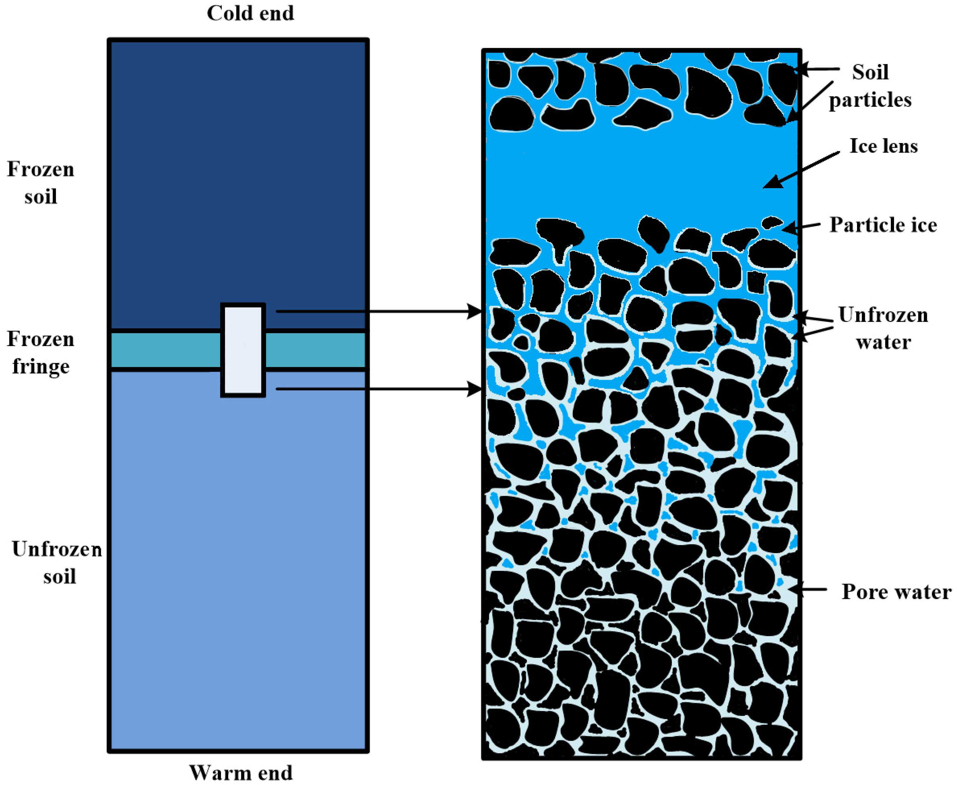
Soil freezing is a thermo-hydro-mechanical coupling process caused by a temperature gradient, and the coupling relationship of soil freezing can be shown in Figure 1. Due to the adsorption of the soil particles, the water film between the particles is kept in a liquid state when the temperature is lower than the freezing temperature. When the temperature continues to decrease, the water film begins to freeze, and with the ice wedging between the particles, the soil particles are separated. Under the appropriate condition of water replenishment and temperature, the ice layer between the soil particles becomes thicker to form the ice lens [19]. It has been widely accepted by scholars that phase change of the pore water and the formation of ice lens occur in the so-called ‘frozen fringe’ and the stress criterion is considered as the criteria for the formation of a new ice lens [12,20,21,22]. Thomas et al. [21] thought that a new ice lens forms when the pore pressure exceeds the sum of the separation strength and the overburden stress of the freezing soil. Cao and Liu [23] found that if the pore pressure criterion is used, the distribution of ice pressure will be discontinuous, and there are errors between the simulation results and experimental data. The simulation results using the ice pressure criterion are closer to the experimental data.
In this study, a new thermo-hydro-mechanical coupling model is established to describe the freezing process in soil. The coupling relationship between the physical fields is shown in Figure 1. The effects of the initial void ratio, hydraulic conductivity, and thermal conductivity of soil particles on soil freezing process are explored. A new condition for the formation of ice lenses is proposed. In this model, the following items are assumed:
(1)
The pores of soil are filled with water and ice during freezing, and the soil is regarded as isotropic and elastic mediums.
(2)
The pore ice is immobile relative to the soil skeleton.
(3)
The soil particles, pore ice, and water are incompressible.
(4)
A weighting algorithm is used to convert the soil of the three-phase system into a single-phase system for the calculation of heat transfer.

2. Theoretical Model of Soil Freezing

According to the theory of adsorption, the pore water is not frozen completely when the temperature is below the freezing temperature, and the unfrozen water adsorbs on the surface of the soil particles, and the thickness of the water film mainly depends on the temperature [24]. This process can be illustrated in Figure 2.

2.1. Heat Transfer

In the process of soil freezing, heat transfer and heat convection occur according to the thermodynamics theory. The evolution of the temperature field conforms to the law of conservation of energy. The heat conduction equation for soil freezing can be expressed as:
( Φ d V ) t + ( λ T ) d V + ρ l c l T · v d V = 0
where t is time; T is temperature; c l and ρ l are the specific heat capacities and the density of pore water, respectively; is the Hamiltonian operator and means = x + y (in two dimensions); Φ represents the heat content of soil per unit volume; d stands for the differential operator; d V refers to the volume element of the soils; λ refers the thermal conductivity; and v is the seepage velocity of pore water:
Φ = H ( T T r ) L n S i ρ i
where L is the latent heat of water phase change; n represents the porosity of the soil; S i is the ice volume percentage in pores; T r is the reference temperature; ρ i is the density of ice; H is the volumetric heat capacity of soil, which can be expressed as:
H = ( 1 n ) ρ s c s + ( 1 S i ) n ρ l c l + S i n ρ i c i
where ρ s is the density of the soil particles, and c s and c i are the specific heat capacities of the soil particles and ice, respectively. Tice et al. [25] established a relationship between the ice percentage S i and temperature based on the results of experiments as follows:
S i = { 1 [ 1 ( T T 0 ) ] α T T 0 0 T > T 0
where T0 is the freezing point temperature (273.15 K) of water in pores ignoring the effect of the water vapor sorption isotherm [21,22,25,26,27], and here α is a parameter depending on the pore size of soil:
d V = ( 1 + e ) d V s
where e and d V s are the porosity ratio and the soil particle volume of soil element, respectively:
λ = λ s ( 1 n ) λ l ( 1 S i ) n λ i n S i
Substituting Equations (2), (3), and (5) into Equation (1) and assuming that the solid particles are incompressible, the equations of heat transfer can be written as:
C 11 T t + C 12 1 1 + e e t + ( λ T ) + ρ l c l T · v = 0
C 11 = [ H + e 1 + e ( T T r ) ( ρ i c i ρ l c l ) S i T e 1 + e L ρ i S i T ]
C 12 = [ ( 1 S i ) ρ l c l + S i ρ i c i ] ( T T r ) L S i ρ i

2.2. Mechanical Equilibrium

During the freezing process of the soil, the skeleton of the soil is filled with pore ice and water. The total stress of frozen soil is equal the sum of the skeleton stress and pore pressure. According to Biot’s effective stress law [28], the equilibrium equation can be expressed as:
σ i j , j e + α * P , i + f i = 0
where σ i j e is the effective stress tensor; α * is the Biot coefficient; P is the pore pressure; and f i is the body force in the ith direction:
α * = 1 K K s
where K is the bulk modulus of the soil skeleton, and K s is the bulk modulus of soil particles.
The total stress σ 11 in the vertical direction can be expressed as:
σ 11 = P o b + x h γ d x *
where P o b is the overburden pressure of the soil column; h is the height of the soil column; and γ is the unit weight.
According to the composition of frozen soil, the unit weight γ can be calculated by the following equation:
γ = g [ ( 1 n ) ρ s + n S i ρ i + n ( 1 S i ) ρ l ] ,
where g is the gravitational acceleration.
Therefore, the initial total stress σ 11 0 can be written as:
σ 11 0 = P o b + x h γ 0 d x *
and the initial unit weight γ 0 can be given as:
γ 0 = g [ ( 1 n 0 ) ρ s + n 0 ρ l ]
where n 0 is the initial porosity, n 0 = e 0 1 + e 0 , and e 0 is the initial porosity ratio.
Based on the principle of effective stress, the relationship of the total stress σ 11 , the effective stress σ 11 e , and pore pressure P can be written as:
σ 11 = σ 11 e + P
For isotropic porous media materials, the relationship between the effective stress tensor and the strain tensor can be expressed as:
σ i j e = λ * ε k k δ i j + 2 μ * ε i j + ( σ i j 0 P 0 )
where λ * and μ * are the Lame constant; ε k k is the volume strain and ε k k = ε 11 + ε 22 + ε 33 ; ε 11 ,   ε 22 ,   ε 33 are the normal strain; δ i j is the Kronecker symbol; σ i j 0 is the initial total stress tensor; and P 0 is the initial pore pressure.
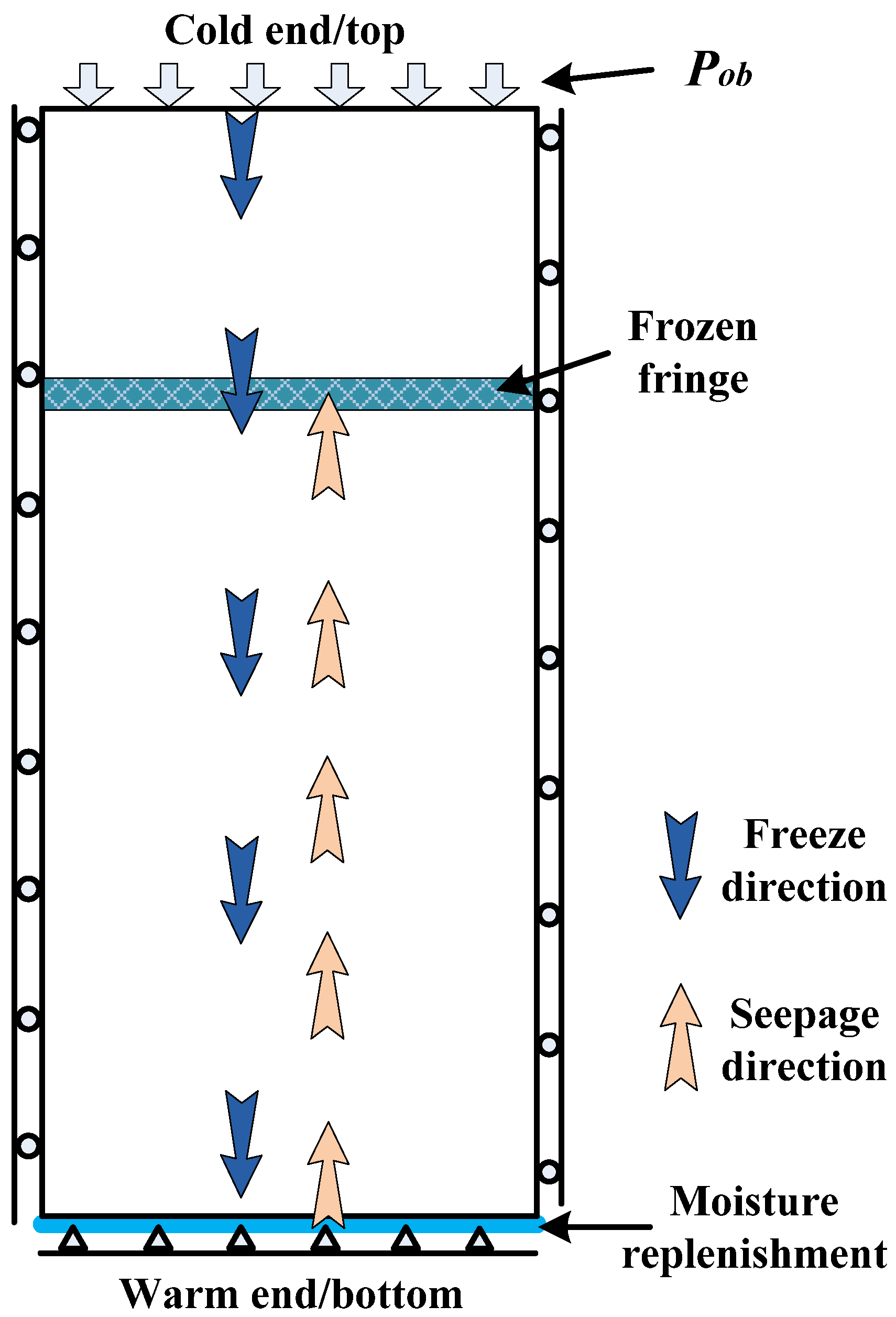
The freezing process of the soil layer is simulated, and the schematic diagram of the soil column model is shown in Figure 3. When shallow soil freezes in the natural environment, frost heave does not occur in the horizontal direction. From Figure 3, it can be seen that the horizontal strains of the model meet the condition ε 22 = ε 33 = 0 and ε k k = ε 11 . Equation (15) can be written as:
σ 11 e = λ * ε 11 + 2 μ * ε 11 + σ 11 0
Soil particles are assumed to be undeformed, and the frost heave is derived from the expansion of the pores. Before the deformation, the void ratio was e 0 ; the volume of soil particles is A; and the volume of pores is (1 − A). After the deformation, the void ratio is e ; the volume of soil particles is A; and the volume of pores is Q. The following relationships can be obtained:
e 0 = 1 A A
e = Q A
The volumetric strain can be expressed as:
ε k k = ε 11 = Q ( 1 A ) 1
Substituting Equations (17) and (18) into Equation (19), the ε 11 can be written as:
ε k k = ε 11 = e e 0 1 + e 0
P = σ 11 σ 11 e
Substituting Equations (10), (12), (16), and (20) into Equation (21), the pore pressure equation can be rewritten as:
P = x h ( γ γ 0 ) d x * + E ( 1 ν ) ( e e 0 ) ( 1 + e 0 ) ( 1 + ν ) ( 1 2 ν )
where E is the compressive modulus and ν is Poisson’s ratio.
From the soil damage criterion, we can get the following formula:
P σ 11 σ s e p
where σ s e p is the separation strength of the freezing soil (negative value for tensile strength).
Substituting Equation (22) into Equation (23) and assuming that when e is equal to e n , Equation (23) takes the equal sign, the following relationships can be obtained:
x h ( γ γ 0 ) d x * + E ( 1 ν ) ( e n e 0 ) ( 1 + e 0 ) ( 1 + ν ) ( 1 2 ν ) = σ 11 σ s e p
e n = ( P o b + x h γ 0 d x * σ s e p ) ( 1 + ν ) ( 1 2 ν ) ( 1 + e 0 ) E ( 1 ν ) + e 0
Therefore, the Equation (22) can be expressed as:
P = { x h ( γ γ 0 ) d x * + E ( 1 ν ) ( e e 0 ) ( 1 + e 0 ) ( 1 + ν ) ( 1 2 ν ) e < e n P o b + x h γ d x * σ s e p e e n
Frost heave can be calculated by integrating the strain in height and can be written as:
H i = 0 h ε 11 d x = 0 h e e 0 1 + e 0 d x

2.3. Water Migration

The pore ice is assumed to be fixed during the freezing process, and the pore water is movable relative to the skeleton of soil. According to the law of mass conservation, the governing equation of seepage can be expressed as:
( M a d V ) t + ρ l v d V = 0
where M a is the mass of pore water and ice in the unit volume of soils; v is the velocity relative to the soil particles:
M a = n [ S i ρ i + ( 1 S i ) ρ l ]
v = k γ l ( φ + γ l z )
where k is the hydraulic conductivity; γ l is the weight of unit water; φ is the seepage pressure that consists of the pore pressure P and the cryogenic suction P T (due to the ice/water interface tension) [29], as φ = ( P + P T ) :
k k 0 = { [ 1 ( T T 0 ) ] β T T 0 1 T > T 0
where k0 is the hydraulic conductivity when the soil is unfrozen, T0 is the freezing point temperature (273.15 K) of water in pore ignoring the effect of the water vapor sorption isotherm [21,22,26,27], and β is a parameter depending on the size and structure of pore.
During the soil freezing process, the experimental results showed that the temperature gradient will cause the pore water to migrate from the high-temperature region to the low-temperature region [9]. The Clapeyron equation is presented to describe the relationship between ice pressure, water pressure, and temperature [10]:
P l ρ l + P i ρ i = L ln T T 0
where P l and P i are the water pressure and ice pressure, respectively.
The cryogenic suction P T can be expressed as [12]:
P T = P l P i ρ l L T T 0 T 0
Substituting Equations (29), (30), and (33) into Equation (28), the governing equation of water transfer can be written as:
C 21 T t + C 22 1 1 + e e t + ρ l ( k γ l P ) + ρ l ( k ρ l L γ l T 0 T ) + ρ l ( k z ) = 0
C 21 = n ( ρ i ρ l ) S i T
C 22 = S i ρ i + ( 1 S i ) ρ l .

2.4. Ice Segregation

According to Miller’s second theory of frost heave, there is a frozen fringe in the process of soil freezing, and a new ice lens is formed in the frozen fringe. The development of the mechanical method is relatively complete because the mechanical method is relatively visualized and has a clear physical meaning. In 1961, Bishop gave an expression for pore pressure in unsaturated soils. Miller [30] applied the expression to saturated freezing soils as:
P = χ P l + ( 1 χ ) P i
where χ is a weighting coefficient, and can be expressed as the following Equation [31]:
χ = ( 1 S i ) 1.5
According to Equation (32), the pore water pressure can be obtained as:
P l = ρ l ρ i P i + ρ l L ln ( T T 0 )
Substituting Equation (37) into Equation (35), the relationship between P and P i can be obtained as:
P = [ ρ l ρ i χ + ( 1 χ ) ] P i + χ ρ l L ln ( T T 0 )
P P i + χ ρ l L ln T T 0
The formation of ice lenses occurs when the ice pressure exceeds the sum of the external load and the soil separation strength:
P i σ 11 σ s e p
Substituting Equation (39) into Equation (40), we have:
P χ ρ l L ln T T 0 σ 11 σ s e p
According to Equations (10), (22), and (25), the equivalent form of Equation (41) can be obtained
e [ ( 1 S i ) 1.5 ρ l L ln T T 0 + P o b + x h γ 0 d x * σ s e p ] ( 1 + ν ) ( 1 2 ν ) ( 1 + e 0 ) E ( 1 ν ) + e 0
Equation (42) can be used as the criterion for the formation of ice lenses.
It can be seen from Equation (42) that the formation of ice lenses is related to the temperature, the overburden pressure, and the separation strength of the freezing soil.

3. Model Validation and Numerical Analysis

During the freezing process of soil, moisture will be replenished to the frozen fringe. In this section, the thermo-hydro-mechanical coupling model is used to describe the soil freezing process. After appropriate initial values and boundary conditions are given, the finite element method within the platform of COMSOL Multiphysics can be used to solve the equations to obtain the soil temperature field and displacement field during the freezing process.

3.1. Model Validation

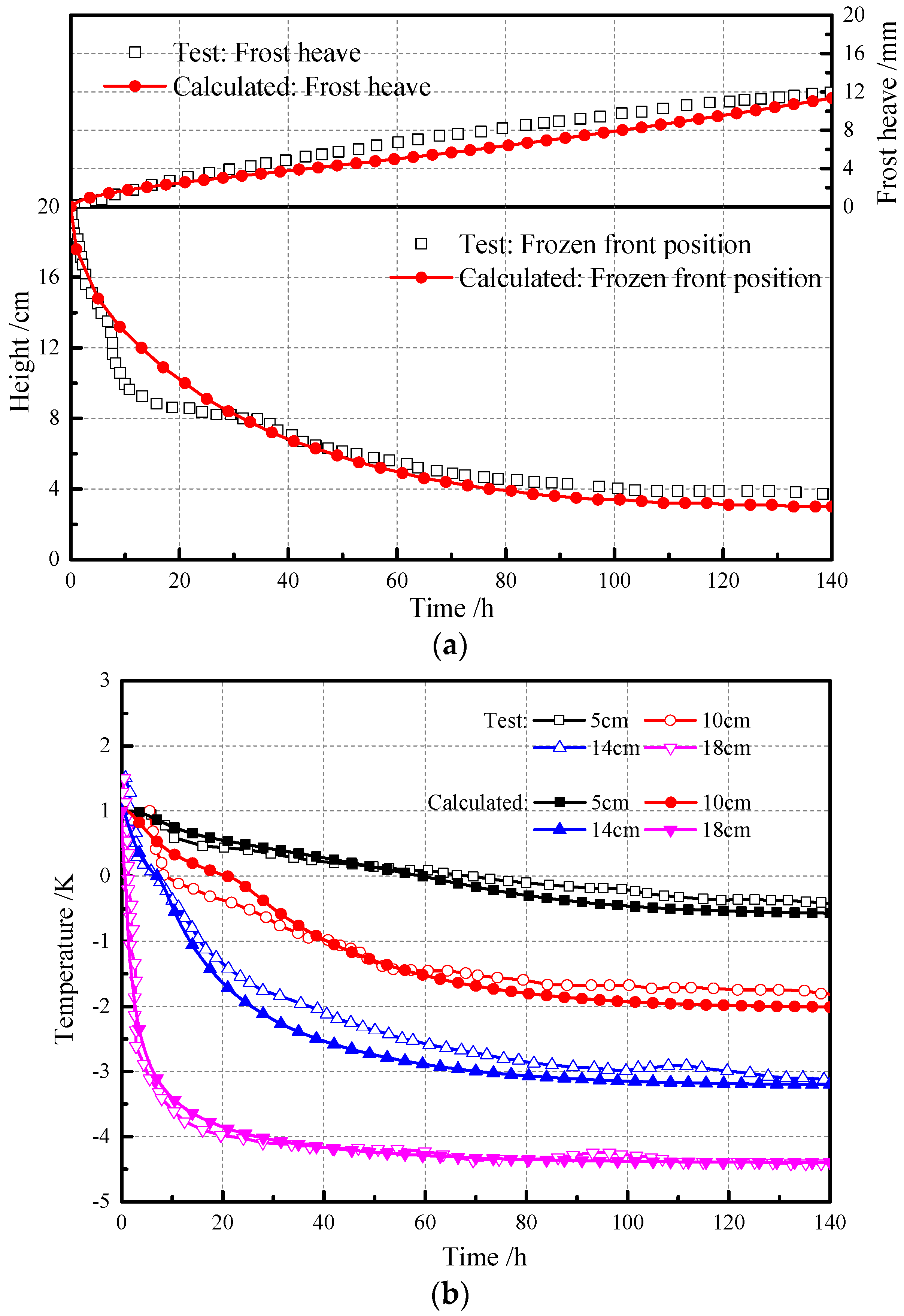
Lai et al. [26] conducted one-side freezing experiments for silty clay column in an open system. The soil column was frozen from top to bottom and water was freely available at the base. The initial water content of the 20 cm soil column was 20.5%; the temperatures of the top and lower surfaces were controlled to 268.15 and 274.15 K; the initial temperature of the soil column was 274.15 K; and the temperature gradient of the soil column was 0.30 K/cm. The lower surface of the soil column can be used for water replenishment. Other parameters related to soil column from Lai et al. [26] are listed in Table 1. The simulation results and experimental data are compared in Figure 4. The frost heave and freezing depth of the soil column are shown in Figure 4a; the relationship between temperatures at the heights of 5, 10, 14, and 18 cm and time are shown in Figure 4b.
From Figure 4a, the frost heave of the soil column continues to increase with the freezing time. The frozen front descends very quickly at the beginning and then descends slowly. From Figure 4b, the temperature of the soil near the cold end descends quickly and then stabilizes. The simulation results of the frost heave, freezing depth, and temperature are almost consistent with the experimental data. As illustrated in Figure 4, the simulation results are consistent with the experimental results.

3.2. The Effect of Soil Parameters on the Soil Freezing Process

The types of soil are different in different regions or different depths. The porosity, thermal conductivity, and water conductivity of different soils are not identical. Previous scholars mainly studied the influence of external conditions on the freezing process of soils, such as the external temperature and overburden pressure [21,31]. There are few reports on the influence of soil properties on the freezing process. The effects of the initial void ratio ( e 0 ), thermal conductivity of soil particles ( λ s ), and hydraulic conductivity ( k 0 ) on the freezing process of soil were analyzed in this study. The parameters of the model required for calculation are listed in Table 2 and these parameters come from Yin et al. [27] and Zhou and Li [22]. In order to analyze the effect of soil properties on the freezing process of the soil column, e 0 , k 0 , and λ s assumed the different values listed in Table 3.
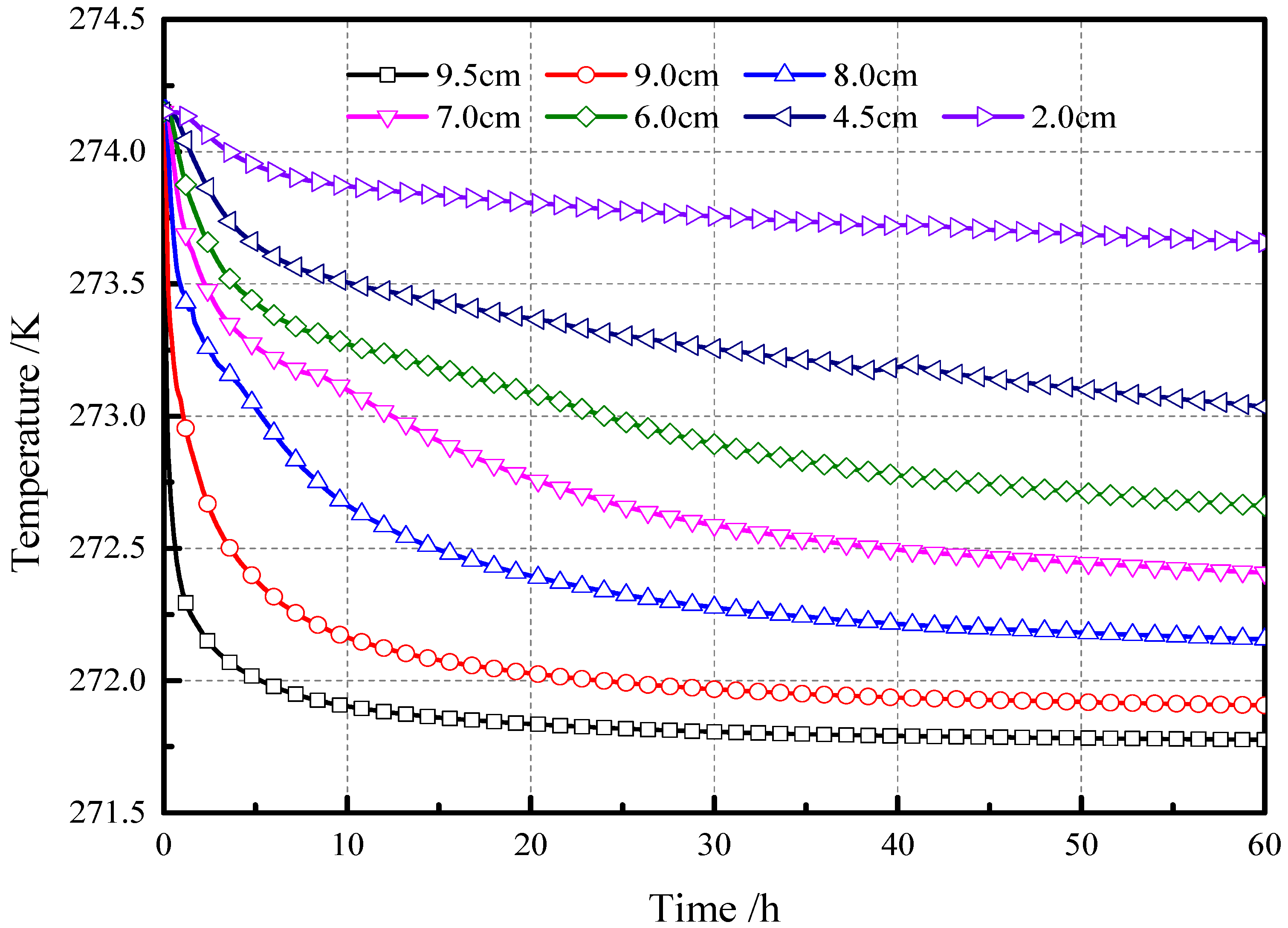
The relationships between temperatures at heights of 9.5, 9, 8, 7, 6, 4.5, and 2 cm and time in case 2 are demonstrated in Figure 5. The temperature drops rapidly near the cold end, which is mainly caused by a large temperature gradient. Near the temperature for 273.15 K, due to the release of latent heat by the phase transition of pore water, the decrease rate of temperature becomes smaller as illustrated in Figure 5. Zhou and Li [22] also obtained similar results.
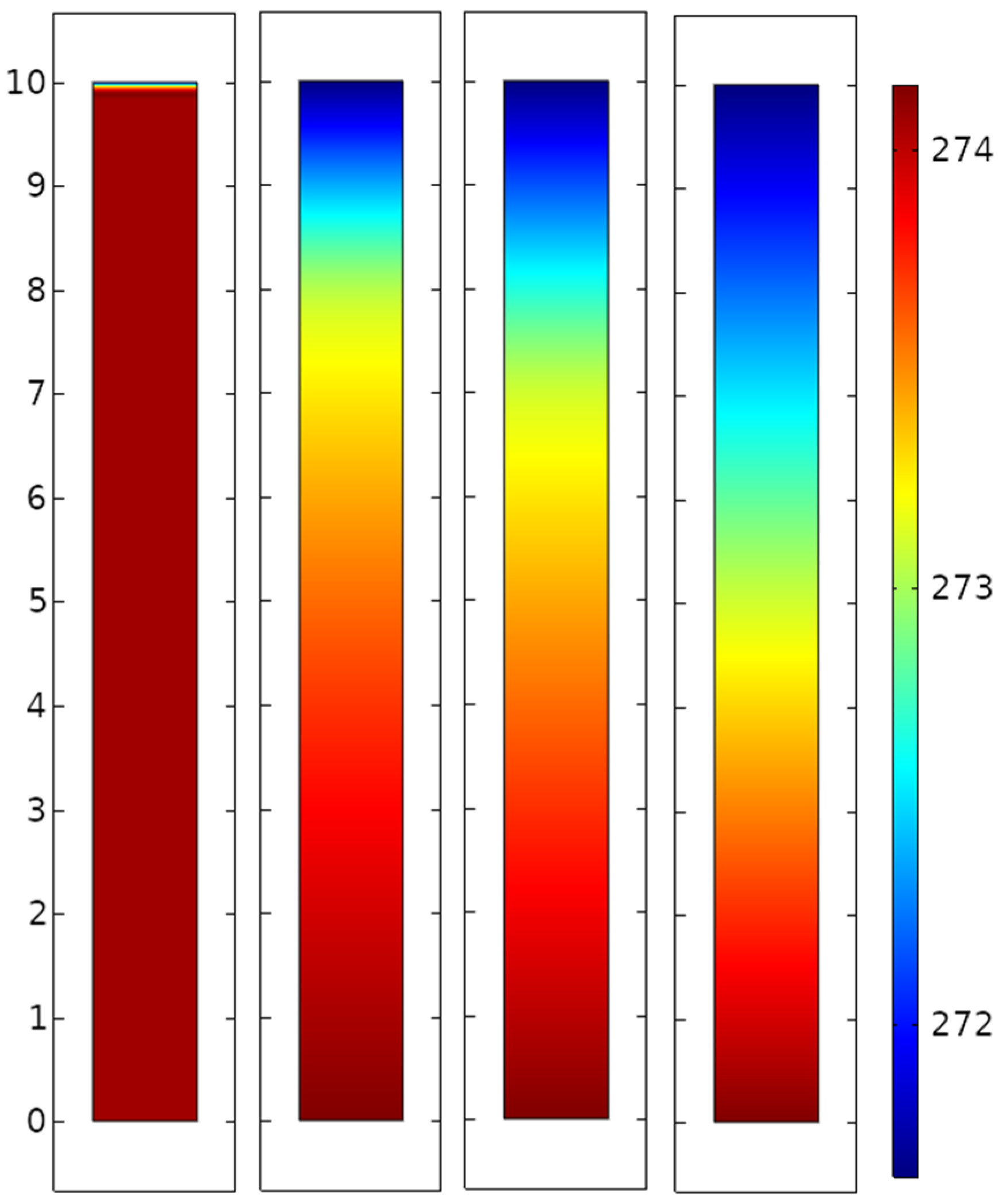
The temperature distributions along the height of the soil column in case 2 are presented in Figure 6. The dotted line corresponds to 273.15 K. The temperature tends to be linear outside of the dotted line region. Near the temperature for 273.15 K, the change of the temperature gradient is mainly caused by the release of latent heat from the phase transition of pore water. The temperature fields at different times in case 2 are shown in Figure 7.
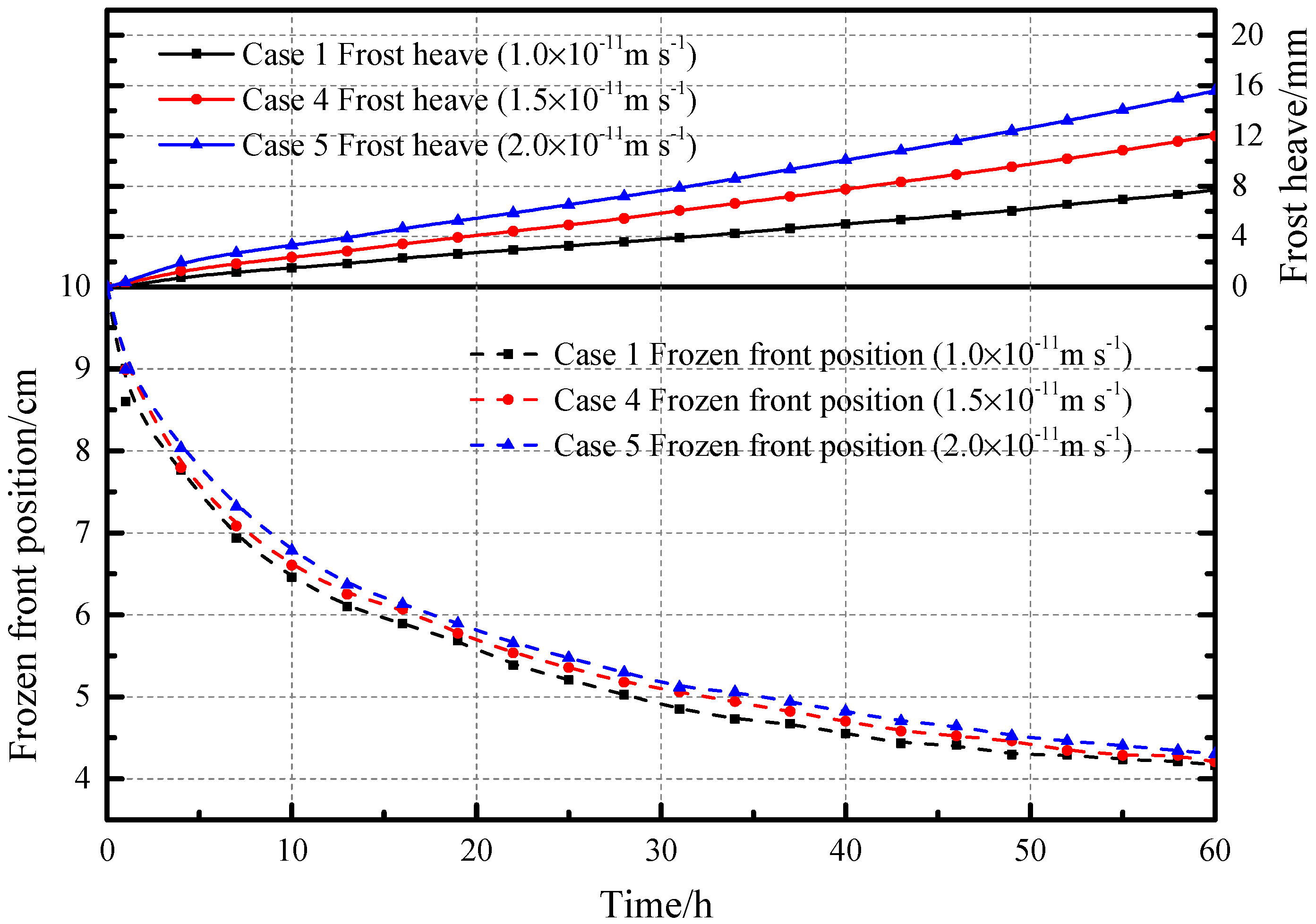
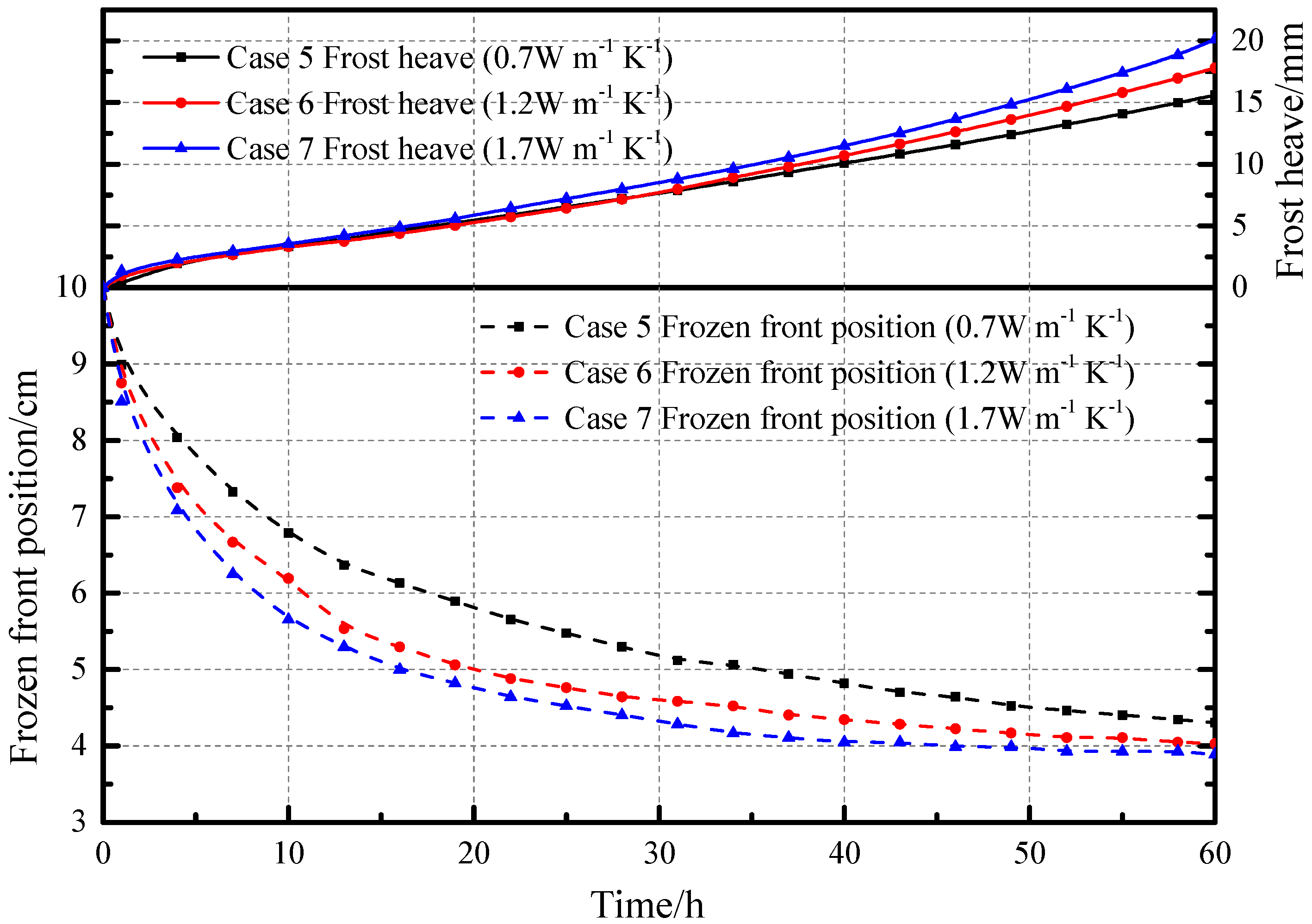
The effects of the initial void ratio ( e 0 ), hydraulic conductivity ( k 0 ), and thermal conductivity of soil particles ( λ s ) on frost heave and frozen front during the freezing process of soil are illustrated in Figure 8, Figure 9 and Figure 10, respectively. It can be seen from Figure 8 that the soil column with a high porosity ratio or a high water content has a more obvious frost heave and a smaller freezing depth at the same freezing time. A high initial void ratio means a high water content; therefore, more latent heat in the soil is released and the freezing depth of the soil column is also reduced. The final positions of the frozen front are basically unchanged.
The frost heave increases by 4 mm for every 0.5 · 10 11   m / s increase in hydraulic conductivity from 1 · 10 11   m / s to 2 · 10 11   m / s after freezing for 60 h, as presented in Figure 9. The seepage of soil is directly affected by the hydraulic conductivity, which causes more water to migrate from the unfrozen region to the frozen front. This leads to a greater release of latent heat. The freezing depth of the soil with high permeability conductivity is slightly smaller, but the change is not obvious. The final positions of the frozen front are basically the same.
The soil with large thermal conductivity causes a great amount of frost heave at the same freezing time. The heat transfer of soil is affected by the thermal conductivity of the soil particles. With the increase of the thermal conductivity, the depth of freezing increases as demonstrated in Figure 10. The freezing depth of the soil column is obviously affected by the change of thermal conductivity. The greater the thermal conductivity of the soil column, the greater the freezing depth. The final positions of the frozen front are basically unchanged. The freezing depth of the soil column with better thermal conductivity reaches a stable position faster.
As it is displayed in Figure 8, Figure 9 and Figure 10 that the frozen front quickly moved downward during the initial period of freezing, the freezing depth is about 5 cm after freezing for 30 h, and the final freezing depth remains about 6 cm. The final temperature is linearly distributed along the height of the soil column in Figure 6, and the finial position of the frozen front depends on the temperatures of the cold and warm ends. Through these seven cases, it can be found that frost heave increases almost linearly with freezing time.
The formation and distribution of ice lenses is important to study the freezing process of soils, the distribution of ice lenses of different cases after freezing 60 h is given in Figure 11, Figure 12 and Figure 13. The white portions represent the ice lenses, and the black portions represent the soil regions. Due to the final stabilization of the frozen front, a thick ice lens, which is called the ‘stable ice lens’ (region B in Figure 12), will be generated near the frozen front, and the ice lenses in region A is called as the ‘previous ice lenses’. Zhou and Li [22], Sheng et al. [32], and Lai et al. [26] obtained similar results about two types of ice lens.
After freezing for 60 h, the results of the cases under different initial void ratios are illustrated in Figure 11. The initial void ratio has little effect on the stable ice lens. This is because the final position of the frozen front will not be affected by the initial void ratio. With the increase of the initial void ratio, the number and thickness of previous ice lenses increase.
The formation of the ice lens is greatly affected by the hydraulic conductivity of soil, as presented in Figure 12. The number and thickness of previous ice lenses are increased in the case with large hydraulic conductivity, and the stable ice lens of soil becomes thicker. It is because the increase of the hydraulic conductivity causes the increase of the moisture of migration. However, there is no obvious change at the bottom of the stable ice lens. The reason is that the stable position of the frozen front is not affected by the hydraulic conductivity.
From Figure 13, the number of previous ice lenses is reduced, and stable ice lens has hardly changed with the increase in thermal conductivity. The large thermal conductivity of soil decreases the freezing time of frozen soil, which prevents further formation and increase of the ice lens in soil.

4. Conclusions and Discussion

In this study, a new thermo-hydro-mechanical coupling model describing the soil freezing process was established considering the formation of ice lenses. The model considered the heat transfer, heat convection, phase change of pore water, mechanical equilibrium, and formation of ice lenses. A new criterion for the formation of ice lenses was derived. Seven cases of soil freezing were simulated to study the effects of the initial void ratio, hydraulic conductivity, and thermal conductivity of soil particles on the freezing process of soils. The following conclusion is made:
The final stable position of the frozen front depends mainly on the temperature of the cold and warm ends, but the freezing front of the soil with a lower initial void ratio and hydraulic conductivity and a large thermal conductivity reaches the stable position faster, and there are fewer previous ice lenses in this case. There was a positive correlation between the frost heave and initial void ratio, hydraulic conductivity, and thermal conductivity. The stable ice lens is mainly affected by the hydraulic conductivity, and as it increases, the thickness of the stable ice lens becomes larger.
Because of the compressibility of soil particles, pore ice and pore water are ignored, and the applicability of the model will be reduced when used to study the freezing of deep soil. The research object of the theory proposed in this paper was saturated soil. For unsaturated soil, the degree of saturation needs to be introduced into the theory to adjust the model.

Author Contributions

D.L. Methodology, Investigation, Software, Writing—original draft. Y.Y. Conceptualization, Supervision, Writing—review and editing. C.C. Conceptualization, Writing—review and editing. Y.C. Data curation, Formal analysis. S.W. Resources, Formal analysis. All authors have read and agreed to the published version of the manuscript.

Funding

This research was funded by the Fundamental Research Funds for the Central Universities, grant number 2019ZDPY18.

Acknowledgments

The authors are grateful to the editor and reviewers for providing constructive and positive comments for this paper.

Conflicts of Interest

The authors of this manuscript declare not to have any conflict of interest regarding this manuscript. None of the authors have any financial interests with any commercial entity that has interest in the subject or outcome of this manuscript including consultancy, paid expert consultancy, or honoraria, patent application, as well as other forms of conflict of interest, including personal and academic issues. The authors to the best of their knowledge conducted the study and reported the conclusions independently without any interference from partial or full funding sources or other entities.

Abbreviations

e pore ratio
n porosity
P pore pressure, Pa
t time, s
T temperature, K
σ i j ,   σ i j e total stress tensor and effective stress tensor, Pa
σ 11 normal stress in vertical direction, Pa
ε i j strain tensor
ε 11 ,   ε 22 ,   ε 33 normal strain Constants and symbols
c s ,   c l ,   c i specific heat capacities of solid particles, pore water and pore ice, respectively, J·kg−1·K−1
d V unit volume element of soils, m3
e 0 initial porosity ratio
E compressive modulus, Pa
f i body force in the ith direction, Pa·m−1
g gravitational acceleration, m·s−2
h height of soil model, cm
H volumetric heat capacity of the soils, J·K−1·m−3
H i frost heave, m
K ,   K S the bulk modulus of dry soil and soil particles, respectively, Pa
k ,   k 0 hydraulic conductivity of freezing soils and unfrozen soils, respectively, m·s−1
L latent heat of fusion for water, J·kg−1
M a mass of pore water and ice in the unit volume of soils, kg·m−3
P i , P l ice and water pressures, respectively, Pa
P T cryogenic suction due to the ice/water interface tension, Pa
P o b overburden pressure, Pa
S i volume percentage of ice in pores
T 0 freezing point temperature of water in pore, K
T r reference temperature, K
v seepage velocity of pore water, m·s−1
α parameter depending on the size of pore
α * Biot coefficient
β parameter dependent on the size and structure of pore
Φ heat content of soil per unit volume, J·m−3
λ thermal conductivity of freezing soils, J·m−1·s−1·K−1
λ s ,   λ l ,   λ i thermal conductivity of soil particles, water and ice, respectively, J·m−1·s−1·K−1
ρ s ,   ρ l ,   ρ i density of soil particles, water and ice, respectively, kg·m−3
γ unit weight of soil, kg·m−2·s−2
γ l unit weight of water, kg·m−2·s−2
σ s e p separation strength of the freezing soil, Pa
σ 11 0 initial normal stress in vertical direction, Pa
λ * ,   μ * Lame constant
ν Poisson’s ratio of soil
Hamiltonian operator
d differential operator
φ driving force that causes seepage
χ weighting coefficient
δ i j Kronecker symbol

References

  1. Monrabal-Martinez, C.; Scibilia, E.; Maus, S.; Muthanna, T.M. Infiltration response of adsorbent amended filters for stormwater management under freezing/thawing conditions. Water 2019, 11, 2619. [Google Scholar] [CrossRef] [Green Version]
  2. Steelman, C.M.; Endres, A.L.; Kruk, J.V.D. Field observations of shallow freeze and thaw processes using high-frequency ground-penetrating radar. Hydrol. Process. 2010, 24, 2022–2033. [Google Scholar] [CrossRef]
  3. Rivas, T.; Alvarez, E.; Mosquera, M.J.; Alejano, L.; Taboada, J. Crystallization modifiers applied in granite desalination: The role of the stone pore structure. Constr. Build. Mater. 2010, 24, 766–776. [Google Scholar] [CrossRef]
  4. Hu, W.L.; Liu, Z.Q.; Pei, M. Effect of air entraining agent on sulfate crystallization distress on sulphoaluminate cement concrete. Mater. Rep. 2019, 33, 239–243. [Google Scholar]
  5. Chen, P.; Luo, H.; Liu, E. Moisture Transfer and Formation of Separate Ice in the Freezing Process of Saturated Soils. Water 2020, 12, 1044. [Google Scholar] [CrossRef] [Green Version]
  6. Taber, S. The mechanics of frost heaving. J. Geol. 1930, 38, 303–317. [Google Scholar] [CrossRef]
  7. Everett, D.H. The thermodynamics of frost damage to porous solids. Trans. Faraday Soc. 1961, 57, 1541–1551. [Google Scholar] [CrossRef]
  8. Harlan, R.L. Analysis of coupled heat-fluid transport in partially frozen soil. Water Resour. Res. 1973, 9, 1314–1323. [Google Scholar] [CrossRef] [Green Version]
  9. Mageau, D.W.; Morgenstern, N.R. Observations on moisture migration in frozen soils. Can. Geotech. J. 1980, 17, 54–60. [Google Scholar] [CrossRef]
  10. Kay, B.D.; Groenevelt, P.H. On the interaction of water and heat transport in frozen and unfrozen soils: I. Basic theory; the vapor phase 1. Soil Sci. Soc. Am. J. 1974, 38, 395–400. [Google Scholar] [CrossRef]
  11. Miller, R.D. Freezing and heaving of saturated and unsaturated soils. Highw. Res. Rec. 1972, 393, 1–11. [Google Scholar]
  12. Gilpin, R.R. A model for the prediction of ice lensing and frost heave in soils. Water Resour. Res. 1980, 16, 918–930. [Google Scholar] [CrossRef]
  13. Konrad, J.M.; Morgenstern, N.R. A mechanistic theory of ice lens formation in fine-grained soils. Can. Geotech. J. 1980, 17, 473–486. [Google Scholar] [CrossRef]
  14. Nishimura, S.; Gens, A.; Olivella, S.; Jardine, R.J. THM-coupled finite element analysis of frozen soil: Formulation and application. Geotechnique 2009, 59, 159–171. [Google Scholar] [CrossRef] [Green Version]
  15. Tan, X.; Chen, W.; Tian, H.F.; Cao, J. Water flow and heat transport including ice/water phase change in porous media: Numerical simulation and application. Cold Reg. Sci. Technol. 2011, 68, 74–84. [Google Scholar] [CrossRef]
  16. Wu, D.; Lai, Y.; Zhang, M. Heat and mass transfer effects of ice growth mechanisms in a fully saturated soil. Int. J. Heat Mass Transf. 2015, 86, 699–709. [Google Scholar] [CrossRef]
  17. Song, W.; Zhang, Y.; Li, B.; Fan, X. A lattice Boltzmann model for heat and mass transfer phenomena with phase transformations in unsaturated soil during freezing process. Int. J. Heat Mass Transf. 2016, 94, 29–38. [Google Scholar] [CrossRef]
  18. Xu, F.; Zhang, Y.; Liang, S.; Li, B.; Hu, Y. Model development for infiltration of unfrozen water in saturated frozen soil using lattice Boltzmann method. Int. J. Heat Mass Transf. 2019, 141, 748–756. [Google Scholar] [CrossRef]
  19. Hongzhang, C. Research on Fields Coupling in Saturated Granular Soil Freezing Process; Institute of Engineering Thermophysics, Chinese Academy of Sciences: Beijing, China, 2016. [Google Scholar]
  20. Nixon, J.F. Discrete ice lens theory for frost heave in soils. Can. Geotech. J. 1991, 28, 843–859. [Google Scholar] [CrossRef]
  21. Thomas, H.R.; Cleall, P.J.; Li, Y.; Harris, C.; Kern-Luetschg, M. Modelling of cryogenic processes in permafrost and seasonally frozen soils. Geotechnique 2009, 59, 173–184. [Google Scholar] [CrossRef]
  22. Zhou, J.; Li, D. Numerical analysis of coupled water, heat and stress in saturated freezing soil. Cold Reg. Sci. Technol. 2012, 72, 43–49. [Google Scholar] [CrossRef]
  23. Hongzhang, C.; Shi, L. One dimension simulation of the rigid ice model of saturated freezing granular soil. J. Glaciol. Geocryol. 2007, 29, 32–38. [Google Scholar]
  24. Anderson, D.M.; Hoekstra, P. Crystallization of clay-adsorbed water. Science 1965, 149, 318–319. [Google Scholar] [CrossRef]
  25. Tice, A.R.; Anderson, D.M.; Banin, A. The Prediction of Unfrozen Water Contents in Frozen Soils from Liquid Limit Determinations; Cold Regions Research and Engineering Lab Hanover: Hanover, NH, USA, 1976. [Google Scholar]
  26. Lai, Y.; Pei, W.; Zhang, M.; Zhou, J. Study on theory model of hydro-thermal-mechanical interaction process in saturated freezing silty soil. Int. J. Heat Mass Transf. 2014, 78, 805–819. [Google Scholar] [CrossRef]
  27. Yin, X.; Liu, E.; Song, B.; Zhang, D. Numerical analysis of coupled liquid water, vapor, stress and heat transport in unsaturated freezing soil. Cold Reg. Sci. Technol. 2018, 155, 20–28. [Google Scholar] [CrossRef]
  28. Biot, M.A.; Willis, D.G. The Elastic Coefficients of the Theory of Consolidation. J. Appl. Mech. 1957, 24, 594–601. [Google Scholar]
  29. Nakano, Y. Quasi-steady problems in freezing soils: I. Analysis on the steady growth of an ice layer. Cold Reg. Sci. Technol. 1990, 17, 207–226. [Google Scholar] [CrossRef]
  30. Miller, R.D. Lens initiation in secondary heaving. In Proceedings of the International Symposium on Frost Action in Soils, Lulea, Sweden, 16–18 February 1977; pp. 68–74. [Google Scholar]
  31. O’Neill, K.; Miller, R.D. Exploration of a rigid ice model of frost heave. Water Resour. Res. 1985, 21, 281–296. [Google Scholar] [CrossRef]
  32. Sheng, D.; Zhang, S.; Yu, Z.; Zhang, J. Assessing frost susceptibility of soils using PCHeave. Cold Reg. Sci. Technol. 2013, 95, 27–38. [Google Scholar] [CrossRef] [Green Version]
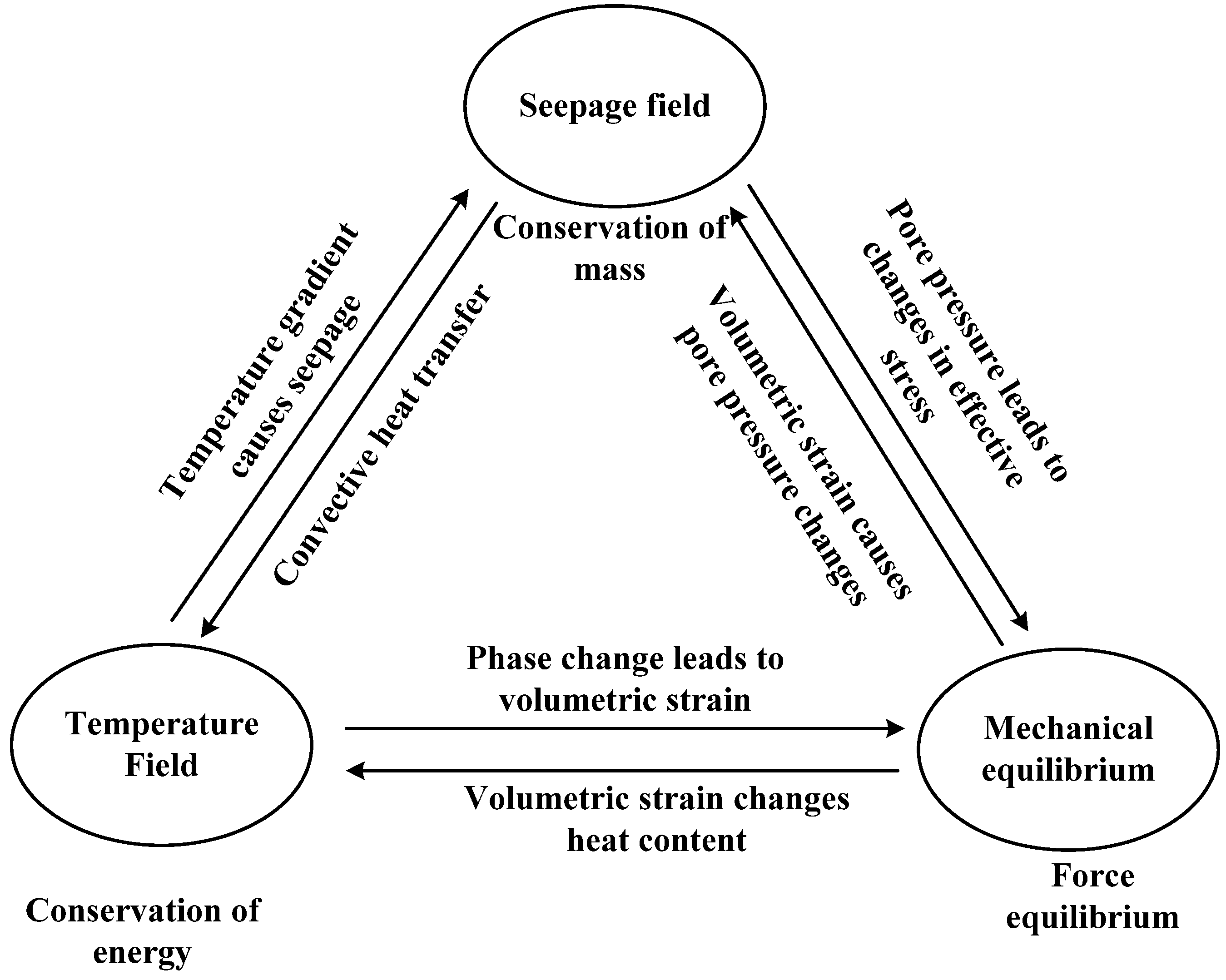
Figure 1. Coupling relationship of physical fields in soil freezing.
Water 12 02684 g001
Figure 2. Microscopic schematic of soil freezing.
Water 12 02684 g002
Figure 3. Schematic diagram of the soil column mechanical model.
Water 12 02684 g003
Figure 4. Comparison between simulation results and experimental data. (a: Frost heave profiles and frozen front profiles during freezing process; b: Temperature profiles at the heights of 5, 10, 14, and 18 cm during freezing process).
Water 12 02684 g004
Figure 5. The temperature evolution curve of the soil column with different heights.
Water 12 02684 g005
Figure 6. Temperature distribution at different times of case 2.
Water 12 02684 g006
Figure 7. Temperature distribution at 0, 5, 10, and 35 h of case 2.
Water 12 02684 g007
Figure 8. Freezing process curves of cases 1, 2, and 3.
Water 12 02684 g008
Figure 9. Freezing process curves of cases 1, 4, and 5.
Water 12 02684 g009
Figure 10. Freezing process curves of cases 5, 6, and 7.
Water 12 02684 g010
Figure 11. Distribution of ice lenses at different initial void ratios. (Region A is called the ‘previous ice lenses’; Region B is called the ‘stable ice lens’.).
Water 12 02684 g011
Figure 12. Distribution of ice lenses at different hydraulic conductivity.
Water 12 02684 g012
Figure 13. Distribution of ice lenses at different thermal conductivity of solid particles.
Water 12 02684 g013
Table 1. List of parameters used in the model validation.
ParameterValue
Density of solid particles, ρ s (kg/m3)2360
Density of water, ρ l (kg/m3)1000
Density of ice, ρ i (kg/m3)917
thermal conductivity of water, λ l (J·m−1·s−1·K−1)0.58
thermal conductivity of ice, λ i (J·m−1·s−1·K−1)2.22
thermal conductivity of solid particles, λ s (J·m−1·s−1·K−1) 1.5
Specific heat capacities of solid particles, c s (J·kg−1·K−1)2360
Specific heat capacities of water, c l (J·kg−1·K−1)4180
Specific heat capacities of ice, c i (J·kg−1·K−1)1874
Gravitational acceleration, g (m/s2)9.81
Height of soil model, h (cm)20
Latent heat of fusion for water, L (J/kg)334,560
Table 2. List of parameters used in the calculation examples.
ParameterValue
Density of solid particles, ρ s (kg/m3)2700
Density of water, ρ l (kg/m3)1000
Density of ice, ρ i (kg/m3)917
Compressive modulus, E (MPa)0.8
thermal conductivity of water, λ l (J·m−1·s−1·K−1)0.58
thermal conductivity of ice, λ i (J·m−1·s−1·K−1)2.22
Specific heat capacities of solid particles, c s (J·kg−1·K−1)2360
Specific heat capacities of water, c l (J·kg−1·K−1)4180
Specific heat capacities of ice, c i (J·kg−1·K−1)1874
Gravitational acceleration, g (m/s2)9.8
Height of soil model, h (cm)10
Latent heat of fusion for water, L (J/kg)334,000
Overburden pressure, P o b (kPa)200
Table 3. Values of the variables in the simulated cases.
Case No.Initial Void RatioInitial Hydraulic Conductivity
(10−11m s−1)
Temperatures of Top and Lower Surfaces (K)Thermal Conductivity of Soil Particles
(W·m−1 K−1)
10.41.0271.65/274.150.70
20.61.0271.65/274.150.70
30.81.0271.65/274.150.70
40.41.5271.65/274.150.70
50.42.0271.65/274.150.70
60.42.0271.65/274.151.20
70.42.0271.65/274.151.70