Abstract
The purpose of the present paper is to provide further insights on the definition of the parameters of the log-law in open-channel flows with rough mobile granular beds. Emphasis is placed in the study of flows over cohesionless granular beds composed of monosized spherical particles in simple lattice arrangements. Potentially influencing factors such as grain size distribution, grain shape and density or cohesion are not addressed in this study. This allows for a preliminary discussion of the amount of complexity needed to obtain the log-law features observed in more realistic open-channel flows. Data collection included instantaneous streamwise and bed-normal flow velocities, acquired with a two-dimensional and two-component (2D2C) Particle Image Velocimetry (PIV) system. The issue of the non uniqueness of the definition of the parameters of the log-law is addressed by testing several hypotheses. In what concerns the von Kármán parameter, , it is considered as flow-independent or flow-dependent (a fitting parameter). As for the geometric roughness scale, , it results from a best fit procedure or is computed from a roughness function. In the latter case, the parameter B is imposed as or is calculated from the best fit estimate. The analysis of the results reveals that a flow dependent von Kármán parameter, lower than the constant = , should be preferred. Forcing = leads to non-physical values of and would imply extending the inner layer up about 50% of the flow depth which is physically difficult to explain. Considering a flow dependent von Kármán parameter allows for coherent explanations for the values of the remaining parameters (the geometric roughness scale , the displacement height , the roughness height ). In particular, for the same transport rate, the roughness height obtained in a natural sediment bed is much greater than in the case of bed made of monosized glass spheres, underlining the influence of the bed surface complexity (texture and self-organized bed forms, in the water-worked cases) on the definition of the log-law parameters.
1. Introduction
The classical idealization of flows over smooth and rough boundaries, successfully extended to mobile boundaries, comprises a logarithmic distribution of the longitudinal velocity in the wall-normal direction. In open channel flows, this log-law should be valid in the overlapping layer between inner and outer flow regions (see, e.g., []) when (i) gradients in the longitudinal direction are small, in particular the pressure gradient; (ii) the channel aspect ratio is high so that the mean flow far from the banks or side walls is two-dimensional in the vertical plane and (iii) the relative submersion is high. The log-law can be written as
where is the space and time-averaged longitudinal velocity, is the vertical coordinate above the zero of the log-law (), Z is the vertical coordinate above and arbitrary datum, is the bed’s characteristic roughness height (such that ), is the von Kármán parameter and is the friction velocity (the kinematic scale for both inner and outer flow variables), where is the wall shear stress and is the fluid density.
For hydraulically rough boundaries, the idealization of inner and outer flow regions may not be sufficient to describe the complexity of the flow in the vicinity of the roughness elements. Several conceptual models have been proposed to include in the description of flow stratification a near-bed layer where bed micro-topography determines mean flow features. For the sake of consistency with the early work of some of the authors, the idealization of Ferreira et al. [], depicted in Figure 1, is followed in this text. In region (A), the turbulent flow is influenced by the free-surface. In the inner region (B), the flow is affected by the characteristics of the rough wall, directly in the lowermost layers and indirectly, through , in the uppermost layers. The dominant characteristic length scale in region (B) is , mostly influenced by the diameter of the granular material and its superficial arrangement (the bed micro-topography). The characteristic length scale should be of the order of magnitude of the bed amplitude, (the wall-normal distance between the planes of the troughs and of the crests) but should be dependent on the type of granular bed and on the Shields parameter [].
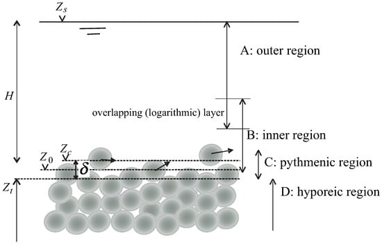
Figure 1.
Idealized physical system. is the elevation of the free-surface, and are the space-averaged elevations of the planes of the crests and of the bed troughs, respectively. The bed amplitude is . All elevations are relative to an arbitrary datum.
The lower boundary of the inner region is set at the elevation of the zero of the log-law, , located above (or below) the boundary zero. is known as the displacement height and can be negative if the zero of the log-law is above the boundary zero. It is noted that the boundary zero is arbitrary. In this text, it is assumed to be contained in the plane of the mean elevation of the crests. Assuming wall similarity in the sense of Townsend [], i.e., balance of production and dissipation rates of turbulent kinetic energy and near-constant Reynolds shear stresses, in the overlapping layer between the inner and outer regions, the wall-normal profile of the longitudinal velocity is expressed by Equation (1). In the pythmenic region (C), whose upper boundary can be located above the plane of the crests if the bedload discharge is large, the flow is three-dimensional and mainly determined by the bed micro-topography and granular movement. Below the elevation of the troughs, , in the hyporheic region (D), the flow may be described by Darcy or Brinkman models [].
The universality of the von Kármán parameter in open-channel flows has long been discussed in the literature. For instance, the assumption of a von Kármán parameter different from a constant value (usually between and ) is discussed in case of flows with low submergence or in the presence of suspended or bedload transport by []. The influence of bed mobility on the value of the von Kármán parameter has been reported for more than 20 years in several experimental studies, normally featuring a reduction of the value of (e.g., []). Gaudio et al. [] have reviewed and published experimental results and have proposed the non-universality of in flows over sediment beds. These authors have shown that, depending on flow characteristics, bed configuration and bedload transport rate, the von Kármán parameter may assume values ranging between and . Gaudio et al. [], analyzing the velocity field in a flume with fixed bed and a sediment supply of coarse sand ( = 1 mm), observed a range of between and with a marked reduction of the value of with increased sediment concentration. These results were obtained assuming a bed Nikuradse sand equivalent roughness of = . In this case, the von Kármán parameter was calculated as , where a is the slope of the semi-log velocity profiles in the logarithmic layer of the inner region. A zero value of zero-plane displacement was estimated following the procedure presented in Koll [].
Recently, Hanmaiahgari et al. [] computed the parameters of the log-law in flows over hydraulically rough mobile beds subjected to different conditions: immobile, weakly mobile and temporally varying mobile bed conditions with different stages of bedform development. The von Kármán parameter was evaluated from the logarithmic law of the wall with the zero of bed-normal axis, z, set at the plane of the crests of the particles (). The displacement height was considered equal to . Their experimental results showed a decrease of due to increase of the thickness of roughness sublayer as the mobility of bedforms increases: the von Kármán parameter varied between in the case of mobile bedforms and for immobile bed conditions. Working with bimodal mixtures of sand and gravel (simulating a natural rough bed), the influence of bedload transport on the values of the von Kármán parameter has been investigated by Ferreira et al. [].
Contrary to the experimental findings of the authors discussed above, Ferreira et al. [] observed that the vertical profiles of the longitudinal velocity, in case of water-worked beds of sand-gravel mixtures, could be fitted to a log-law either with a flow independent () or a flow-dependent von Kármán parameter. They proposed that the value of depends on the interpretation of the log-law parameters such as boundary zero, the geometric roughness scale and the displacement height . They found out that the location of the zero-plane displacement for the log-law could not remain constant and should increase with the increase of the bedload discharge, if is set to . On the contrary, assuming the von Kármán parameter as flow dependent, they showed a decrease in terms of displacement height at the onset of generalized bed load transport, together with a drop on the value of . In both cases, the zero for the log-law was below the plane of the sediment crests. In the wake of Ferreira et al. [], Ferreira [] provided a similarity framework to discuss the nature of in flows over weakly mobile gravel-sand beds and explored a theoretical model for as a function of turbulence parameters. There are three hypotheses of interpretation of his theoretical framework for the cases of: no-similarity, complete similarity or incomplete similarity in the non-dimensional parameters describing bed composition and bed mobility.
In the first case (no similarity), Ferreira [] argued that the vertical distribution of the longitudinal mean velocity would not be logarithmic. If complete similarity exists, on the contrary, all flows characterized by rough mobile beds should be identified by a normalised shear rate in the overlapping layer independent of bed composition and bed mobility and by a constant , not necessarily equal to , independent from Reynolds and Shields numbers. This is the case supported by the laboratory results on the structure of turbulence for flows over rough mobile beds (gravel-sand mixtures) reported in []. The author defends that changes in the structure of turbulence in the inner region do not seem to depend continuously on the Shields number and do not imply a reduction of , in case of mobile bed conditions, with respect to . In the case of incomplete similarity, Ferreira [] proposed a dependency of the constant shear rate on the overlapping layer on bed mobility; was considered a function of bed composition and Shields number. Both complete and incomplete similarity criteria required a joint discussion of and of the displacement height . Ferreira [] and Ferreira et al. [] argued that different choices of may lead to different values of without physical justification.
Bearing in mind that most of the studies above featured sediment beds with different degrees of complexity, the key objective of this paper is to provide insights on the definition of the parameters of the log-law in rough mobile granular beds when complexity is reduced to minimum. Factors influencing surface roughness such as grain size distribution, grain shape and density or cohesion are not addressed in this study. Data collection hence took place in flows over cohesionless granular beds composed by monosized spheres—5 mm glass beads—arranged in simple lattices. These are juxtapositions of close packing arrangements with body-centered cubic arrangements. These experimental tests are meant to clarify the description and interpretation of the parameters of the log-law in rough mobile beds casting aside the complexity introduced by working with natural sediment.
The issue of the nonuniqueness of the definition of the log-law parameters is addressed by analyzing and discussing the experimental results under different scenarios: scenarios 1 and 2 consider constant and equal to and different definitions of geometric roughness scale ; scenarios 3 and 4 retake the definition of reported in the first and second scenario respectively, but the von Kármán parameter is, in this case, considered flow-dependent. The procedures adopted to interpret the laboratorial data follow those of Ferreira et al. []. Issues of universality and uniqueness in the definition of the parameters of the log-law are still important topics of research not only for its intrinsic value—advancing fundamental knowledge—but also because of its direct impacts on the quality of the predicting mathematical modelling tools. The log-law is frequently used as a wall function in Computational Fluid Dynamics (see reviews in e.g., [] or []), in the context of Reynolds-averaged Navier-Stokes equations (RANS) modelling (e.g., [], detached eddy simulation (DES) or even large eddy simulation (LES) modelling ([,]) or integral Navier-Stokes (NS) equation modelling ([]). Furthermore, depth-averaged hydrodynamic and sediment transport models use the parameters of the log-law to estimate the wall shear stress (e.g., [,,]). Improving the accuracy of predictive models for flows over mobile boundaries thus requires investment in the definition of the parameters of the log-law.
2. Laboratory Facilities, Instrumentation and Procedures
Laboratory tests were performed in a m long and cm wide prismatic channel, recirculating water and sediment through independent circuits, installed at the Laboratory of Hydraulics and Environment of Instituto Superior Técnico, Lisbon (Figure 2a). The channel has side glass-walls enabling flow visualization and laser illumination. The flume bed was divided in two main reaches:
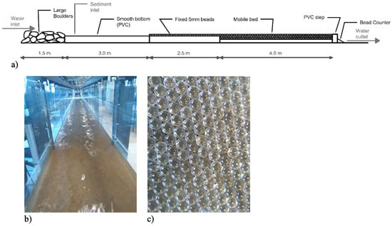
Figure 2.
(a) Scheme of the complete flume setup; (b) general view of the flow over the mobile-bed reach; (c) granular bed, prior to water working, showing the simple lattice arrangement.
- a fixed-bed reach comprising m of large boulders (50 mm average diameter), followed by m of smooth bottom (PVC) and m of one layer of glued spherical glass beads ( mm diameter) to ensure the development of a rough-wall boundary layer (Figure 2a,b);
- a mobile reach m long and cm deep filled with mm diameter glass beads, with density , packed (with some vibration) to a void fraction of , expressing the mixed nature of the lattice arrangement (face-centered and body centered), seen in Figure 2c).
Flow is nearly uniform. In all tests, the energy slope may deviate less than from the channel slope. Since the phenomena of interest to this paper take place in the inner flow layer, this fact is considered not important. Data collected for four experimental tests are discussed in this text: test 1 was performed under sub-threshold conditions (no particles moving), while tests 2, 3 and 4 are respectively characterized by bedload rate of , and beads/s.
Free surface elevation and bed level were measured with mm precision point gage in five transversal sections of the flume and in three lateral positions per cross-section.
The water discharge at the flume inlet was controlled by two digital flowmeters respectively installed on the main water recirculating pump and on the secondary pump recirculating water and sediments. The inlet of the sediments was at m, measured from the main water inlet. The secondary pump provided a constant flow rate of m/s. The flowrate released by the main pump was adjusted depending on the test to obtain the total flow rates reported, among other main characterizing variables, in Table 1.

Table 1.
Characterization of the mean flow.
The other variables in Table 1 are: the mean flow depth, H, defined as the wall-normal distance between and (see Figure 1); the slope of the flume, ; the depth-averaged mean longitudinal velocity, U; the friction velocity and bed shear stress computed from the equation of conservation of momentum in x direction, assuming uniform flow, respectively = and = , where is the water density, is the volumetric weight of the water and is the hydraulic radius; and the friction velocity and the bed shear stress calculated from the wall-normal profile of the wall-normal component of the turbulence kinetic energy, respectively and . The friction velocity was computed as the maximum of the profile . Coefficient C is not universal; Nezu et al. [], for instance, assumed . If the relative importance of the terms of the turbulence kinetic energy is the same as in Nezu et al. [], the coefficient proposed by Soulsby and Dyer [] would be and the coefficient in Stapleton and Huntley [] would be C = . In this study, a constant value of was employed as it minimized the mean square error between and .
Table 2 shows the values of the relevant non-dimensional parameters: Froude number, , Shields parameter, , Reynolds number of the mean flow, (where is the fluid’s kinematic vicosity), bed Reynolds number, and non-dimensional bedload discharge, . The bedload discharge rate was determined by using the particle counting system described in detail in Mendes et al. []. This device was installed at the downstream end of the mobile bed reach of the flume. The pressure variations produced by the impacts of the sediment particles falling on the membrane boxes (placed over the entire width of the channel) were registered and analyzed. The accumulated count registered once flow and sediments’ equilibrium conditions were achieved was then translated into solid flow discharge per each test. The bedload rate was evaluated as , where m is the volume of the glass particles, n is the number of beads impacting on the bead counter per second and b is the channel’s width.

Table 2.
Non-dimensional parameters characterizing the mean flow.
The instantaneous flow velocity (longitudinal u and vertical w) was measured with a two-dimensional and two-component (2D2C) Particle Image Velocimetry (PIV) system, in three different longitudinal positions: cm, cm and cm from the right channel sidewall, where the position at cm represents the center longitudinal section of the flume. The observation window for flow velocity measurements was placed at m from the beginning of the mobile bed reach, covering a length that comprises between 6 cm and 12 cm, depending on the test, and covers the entire flow depth. An acetate sheet was placed on the water surface to ensure optical stability and absence of laser sheet reflections. The PIV system consisted of an 8 bit 1600 × 1200 px CCD camera and a double-cavity solid state laser with pulse energy of 30 mJ at wavelength of 532 nm. The system was operated at 15 Hz with a time between pulses within the range from 380 s to 500 s. Polyurethane particles with mean diameter of 50 mm in a range from 30 to 70 mm and specific density of g/cm were used as solid targets. Such tracer particles have a cut-off frequency of approximately 2500 Hz for a significance level of (Ferreira and Aleixo []). Hence, turbulence with frequencies lower than 2500 Hz is likely to be well-represented by the motion of the tracer particles. Since the PIV was operated at 15 Hz, the Nyquist frequency of the time series is Hz, much smaller than the cut-off frequency. Hence, the employed seeding particles do not constitute an extra limitation to the time resolution of the PIV.
The duration of each PIV time series was 5 min of consecutive data corresponding to 4500 image couples per each measurement position. DynamicStudio software (version 3.41, Dantec Dynamics®, Skovlunde, Denmark) allowed for processing image pairs with the adaptive correlation algorithm. The initial interrogation area was of 128 × 128 px, while the final was of 16 × 16 px, with an overlap of 50%.
3. Data Analysis and Results
3.1. PIV Post-Processing
The images acquired by the PIV system were post-processed by masking the areas in the field of view not occupied by fluid: the band above the free surface (identified as the trace of the laser sheet on the fluid surface) and the region occupied by the bed particles (both immobile and mobile particles). A specially designed algorithm based on thresholding and median and edge filters was developed to automatically detect bed particles edge contours (see details in []). A fixed mask was applied to the time-averaged free surface since its oscillations were small.
Image masking allowed for computing the space–time porosity (Nikora et al. []). Every image domain can be divided in two parts, one occupied by fluid and one by solid (sediment), identified by a clipping or distribution function, , set to 1 in the fluid and 0, otherwise. According to [], the space–time porosity is defined as:
where is the averaging period, is the spatial averaging domain, and is the clipping function. The integration domain is centered at position and t. A local coordinate system in space and time, respectively and , is used for integration.
The velocity profiles discussed in Section 3.2 are the average velocity values of the three longitudinal sections in which PIV acquisition was performed. The boundary zero was set, for each vertical plane, with the criteria presented above. An interpolation in an evenly space grid of discrete increments z = m between the zero and the maximum free surface level was applied before averaging.
3.2. Calculation of the Parameters of the Log-Law
Ferreira et al. [] proposed three possible scenarios to understand their laboratorial data associated with different definitions of the parameters and scale of the log-law. The bed material used in their experiments was a gravel-sand or a gravel mixture depending on the specific test. The location of the boundary zero was set at the elevation of the lowest troughs in scenario () and scenario () and at the plane of the higher crests in scenario ().
In the present experiments, the reference zero is set at the level of the crests of the roughness elements. For practical purposes, and given that particles transported as bedload induce a layer where is less than one, the reference zero was defined as the level of the wall-normal scale corresponding to . The double-averaged longitudinal velocity profiles and the space–time porosities obtained for the central section of the flume are shown in Figure 3.
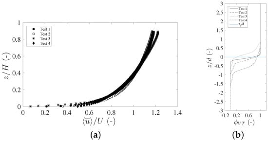
Figure 3.
Double-averaged longitudinal velocity profiles (a) and space–time porosity (b). The reference zero in plot (a) corresponds to the elevation of the particle crests (defined in the text). H is the flow depth measured from this zero. The reference zero in plot (b) corresponds to the initial elevation of the particle crests for Test 1 (no bedload transport).
Following the criteria advanced by Ferreira et al. [], the results of the present experimental study are interpreted in accordance with four different hypotheses:
- the von Kármán parameter is considered flow independent (), the geometric roughness scale and the constant B are subjected to a best fit procedure.
- the von Kármán parameter is considered flow independent (), the constant B is and the roughness scale is calculated from a roughness function.
- the von Kármán parameter is assumed not universal but a fitting parameter, the geometric roughness scale and the constant B are subjected to a best fit procedure.
- the von Kármán parameter is assumed not universal but a fitting parameter and, as in scenario 2, the constant B is imposed equal to and the roughness scale is calculated from a roughness function.
In scenario 1, the displacement height , i.e., the elevation of the zero-plane for the logarithmic law, is derived from:
where = .
A linear regression on the values of Equation (3) renders the value of from the origin of the regression line. Once the displacement height is defined, the remaining parameters of the log-law ( and B) are retrieved from the best fit procedure of the log-law written in the form ([]):
where is the friction velocity (see Table 1) and is the velocity at the lower bound of the logarithmic layer.
The bounds of the regression analysis to determine and B were adjusted to maximize the coefficient of determination while maintaining = .
In scenario 2, the displacement height is retrieved with the same procedure of scenario 1. In this case, the log-law is written as []:
with B = . Equation (5), which is in the form Y = , is fitted to the data with and as fitting parameters. Again, the bounds of the regression were adjusted so that the von Kármán parameter approached . Finally, the scale of the roughness elements is computed from = .
In scenario 3, the data of Equation (3) are fitted to a linear reach with no a priori considerations about the von Kármán parameter . The geometric scale of the roughness elements is computed as in scenario 1.
Once the bounds of the regression on the values of Equations (3) and (4) are set in order to maximize the coefficient of determination , the displacement height and the von Kármán parameter are defined through Equation (3), while , through Equation (4).
Scenario 4 differs from scenario 2 in as much as the von Kármán parameter is not considered universal. The value of determined as in scenario 3.
Finally, the roughness height, , can be computed from applying the following relation, valid for all four approaches:
where B, and are the parameters found for each scenario. The values of the log-law parameters are displayed in Table 3, Table 4 and Table 5.

Table 3.
Parameters describing the log-law for Scenario 1, where .

Table 4.
Parameters describing the log-law for Scenario 2, where = and B = .

Table 5.
Parameters describing the log-law for Scenario 3, where is not considered universal.
3.3. Discussion of the Values of the Parameters of the Log-Law
The geometrical outcome of the best fit procedure from which the values of and , shown in Table 3, Table 4, Table 5 and Table 6, were derived can be seen in Figure 4. It is clear in the figures that there are at least two possible ways of fitting a linear model, if different reaches of the wall-normal coordinate are selected. Since the von Kármán parameter is the slope of the regression line and the displacement height depends on the intercept, two possible values of the pair (, ) are derived from the same data set. One of the possible outcomes corresponds to scenarios 1 and 2, for which (Figure 4a,b, respectively). The other possibility corresponds to the flow dependent scenarios 3 and 4 (Figure 4c,d, respectively).

Table 6.
Parameters describing the log-law for Scenario 4, where is not considered universal and B = .
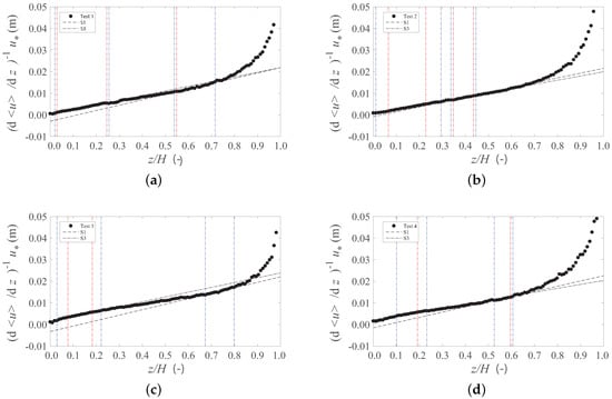
Figure 4.
Shear rate and two-linear reaches identified respectively for Test 1 (a); Test 2 (b); Test 3 (c); Test 4 (d). The regression lines are represented by dashed and dotted lines (as identified in the legend). The bounds of the regression analysis that maximize the determination coefficient are marked with vertical red dashed lines. Blue lines represent the bounds associated with the minimum admissible coefficient of determination— of the maximum coefficient of determination.
The bounds of the regression analysis represented in red in Figure 4 were set so as to maximize the coefficient of determination. Blue lines represent the bounds associated to the minimum admissible coefficient of determination. The latter is set as of the maximum coefficient of determination.
As noted by Ferreira et al. [] and Ferreira et al. [], for rough mobile bed in the presence of bedload transport, the velocity profiles may not be self-similar due to bed mobility affecting the parameters of the log-law. This possibility has been discussed in detail by Ferreira [] and formalized as incomplete similarity in the parameters that describe bed composition and mobility. This is explored in the present study through scenarios 3 and 4 for which the slope of the inverse shear rate is not the same across the tests (Figure 4) and is consistently less than .
From Equation (3), the displacement height is computed as the intercept of the regression line divided by . A small but negative displacement height is obtained for scenarios 3 and 4, corresponding to the flow-dependent . As seen in Table 5 and Table 6, the zero of the log-law is just above the crests of the roughness elements and within the layer where bedload occurs. Positive values of are attained for scenarios 1 and 2 (corresponding to ). The obtained values of are of the order of magnitude of the diameter of the glass beads, which has not been reported in earlier studies.
The double-averaged wall-normal profiles of the longitudinal velocity are depicted in Figure 5 (scenario 1), Figure 6 (scenario 2), Figure 7 (scenario 3) and Figure 8 (scenario 4). The best fit lines resulting from the regression analysis and their lower and upper boundaries are also shown in these figures.
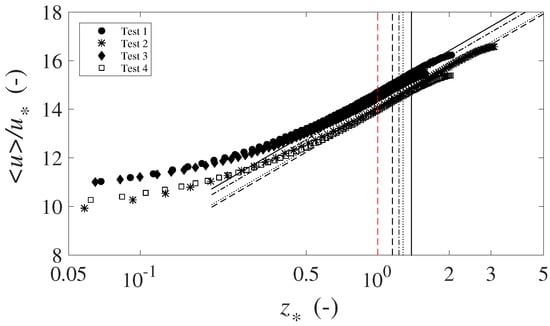
Figure 5.
Double-averaged longitudinal velocity profiles and regression lines for Scenario 1 ( = ), where = . The red vertical line represents the lower bound of the linear reach for all tests, whereas the black vertical lines define the upper bound determined for each test. Test 1 is identified by a solid line, Test 2 by a dash-dot line, Test 3 by a dashed line, while Test 4 by a dotted line.
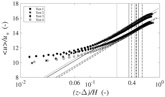
Figure 6.
Double-averaged longitudinal velocity profiles and regression lines for the computation of the scale of the roughness elements , for Scenario 2 ( = , B = ). The bounds of the regression lines are marked with the solid line (Test 1), dash-dot line (Test 2), dashed line (Test 3), and dotted line (Test 4).
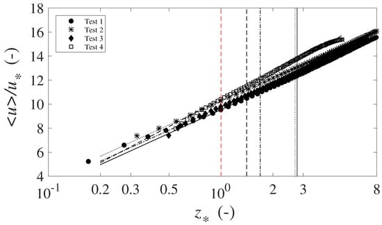
Figure 7.
Double-averaged longitudinal velocity profiles and regression lines for Scenario 3, where = . Vertical line specifications are as in Figure 5.The bounds of the regression lines are marked with solid line (Test 1), dash-dot line (Test 2), dashed line (Test 3), and dotted line (Test 4).
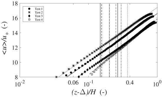
Figure 8.
Double-averaged longitudinal velocity profiles and regression lines for the computation of the scale of the roughness elements , for Scenario 4 (, B = ). The bounds of the regression lines are marked with solid line (Test 1), dash-dot line (Test 2), dashed line (Test 3), and dotted line (Test 4).
In open-channel flows, the overlapping region in which the log-law is defined occurs generally []. In this region, the present data support a Von Kármán parameter lower than . On the other hand, the region characterized by is located well above the lower of the total flow depth (around 35–, depending on the test).
In scenario 1, the values of the scale of the roughness elements , coinciding with the lower bound of the linear reach, are considerably high—between 4 and 8 bead diameters above the reference zero. Parameter B exhibits also relatively high values, well above the classical ([]). In scenario 2, the values for the scale of roughness elements also appear implausible—– bead diameters—since they are less than one bead diameter. The overlapping region between outer and inner region is also observed, as in scenario 1, rather high on the water column (35–).
Without discussing the nature of , the present data show that the adoption of a flow dependent von Kármán parameter, in this case smaller than (scenario 3 and 4), is compatible with a log-law layer as an overlapping of inner and outer flow regions. On the contrary, adopting would imply a log-law layer well in the outer region, which is physically difficult to explain.
It should be noticed that the values of the flow dependent (scenarios 3 and 4) do not seem, however, correlated with the values of the bedload transport rate, as illustrated in Table 5 and Table 6. Irrespectively of the value of the bedload discharge, the von Kármán parameter consistently ranges between and . The scale of the roughness elements increases with the increase of bedload transport rates, both in scenarios 3 and 4, with higher values of found in the latter scenario. The interpretation of as a roughness scale allows for a conjecture about the role of moving bedload particles: since the bed does not suffer strong morphological changes induced by bedload transport, more particles moving should represent a larger work performed by the flow, thus increasing flow resistance, as proposed by Owen []. The displacement height , on the contrary, appears to decrease with increasing solid discharge.
3.4. Discussion of Bed Roughness
The results concerning bed roughness are compared with those shown in Ferreira et al. [], where the velocity profiles of 17 subcritical and nearly uniform flow laboratorial tests are discussed. The channel beds in these two cases are substantially different: while the current study adopted a simple lattice-arranged granular bed with no relevant morphological features even at moderate bedload discharges, the bed surface of Ferreira et al. [] exhibits a complex micro-topography, with clusters around larger particles, in the case of the armoured beds, and low amplitude bedload sheets, in the case of the sand-gravel mixture at high values of the Shields parameter. Porosity is larger in the current study and tortuosity is expected to be smaller. However, the significant diameters that traditionally determine the value of the scale of the roughness elements—the or —are, in the tests of Ferreira et al. [], approximately the same as the diameter of the beads used in the current study. The bedload discharge ranges are equally similar. The simple nature of the bed used in this study allows for an indirect appraisal of the role of the bed micro-topography in determining the geometric scale of the roughness elements and, thus, bottom friction.
The comparison was undertaken for the case where the von Kármán parameter is assumed non-universal (a fitting parameter) and the geometric roughness scale and B are subjected to a best fit procedure (scenario 3).
Figure 9 shows the ratio as a function of the non-dimensional bedload discharge for all 17 tests discussed in Ferreira et al. [] and for the present experiments.
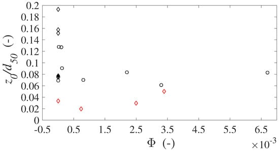
Figure 9.
Variation of the roughness height normalized by the sediment diameter d, as a function of the non-dimensional bedload discharge, for scenario 3. Glass particles data are represented by red open diamonds. Data treated by Ferreira et al. [] of type E are represented by black filled diamonds, type D by black open diamonds and type T by open circles.
One interpretation of the results shown in Figure 9 is that bed organization plays a key role in the relationship between roughness height and . In a high complexity system, as the case of the bi-modal mixture of sand and gravel subjected to the armoring process (test of type D described in [] and represented by black open diamonds), large values of roughness height normalized by the sediment diameter are achieved when bedload transport is incipient ( slightly greater than zero). The armoring process, in fact, due to the presence of larger sediments hiding smaller particles from being eroded, produces the maximum topographic diversity in the bed.
In the case of the bed composed by gravel and sand-gravel mixtures, is relatively high at very low sediment transport rates (around ) when compared with the values obtained for the bed composed of glass beads. This shows that bedload movement in the natural bed generates some kind of bed complexity, whereas the simple lattice-arranged does not generate complexity even under bedload conditions. In fact, the ratio in case of a bed matrix made by monosized glass particles presents lower values (between and ) and just slightly increase with bedload transport.
The bed micro-topography therefore affects the roughness height and hence the remaining log-law parameters , and B. A relevant result is therefore that the roughness height is not correlated with the sediment diameter but depends on bed organization: the more complex the bed topography is, the higher roughness height would be. The large sediment diversity achieved in natural beds responsible for high roughness values can not be obtained with monosized artificial sediments, characterized by a different apparent surface porosity and higher interaction between free-fluid and porous media flows.
4. Conclusions
The experimental analysis reported in this work allowed for testing different definitions of the parameters of the log-law in the specific case of rough mobile bed composed of monosized artificial sediments. Four experimental tests were carried out to assess the effect of bed mobility and increasing bedload transport rates on the wall-normal profile of the longitudinal flow velocity.
The study reveals that a well-fitting log-law profile within the overlapping between outer and inner region ( is achieved assuming a flow-dependent von Kármán parameter , together with geometric roughness scale and parameter B subjected to a best fit procedure (scenario 3) or imposing B = and computing from a roughness function (scenario 4). No substantial dependence of von Kármán parameter on bedload discharge rates was encountered and was found ranging between and , depending on the test, contrary to the wider range of reported in the literature for beds composed of natural sediment.
The zero of the logarithmic profiles was found very near the sediment crests and slightly increasing with bedload transport (scenario 3). Scenario 4 presented small values of as well, although higher than those achieved in scenario 3.
A comparison between the variation of the roughness height normalized by the particle diameter as a function of the bedload discharge, obtained in our simple bed configuration and shown in Ferreira et al. [] for natural beds composed of gravel-sand mixtures, emphasised that the roughness height increases with bed diversity, typical of natural river beds.
The roughness scale is lower in the present tests and higher in the tests with natural sediment, due to the simple configuration of the present bed which prevents the formation of bedload sheets or complex micro-topographical structures.
In the case of glass spheres, the roughness scale increases with bedload transport—it should express the increase in work expended by the flow in maintaining these particles in motion.
The hypothesis that complexity associated with bed micro-topography is more relevant to influence the mean flow than size of the larger elements or bed mobility can thus be put forward and verified.
Author Contributions
Conceptualization, R.M.L.F. and F.A.; methodology, F.A., R.M.L.F. and A.M.R.; formal analysis, F.A., A.M.R. and R.M.L.F.; investigation, F.A., A.M.R. and R.M.L.F.; writing-original draft preparation, F.A.; writing-review and editing, R.M.L.F. and A.M.R., F.A.; visualization, F.A. and A.M.R.; project administration, R.M.L.F.; funding acquisition, R.M.L.F.
Funding
This work was partially funded by Project SEDITRANS funded by the European Commission under the 7th Framework Programme and FEDER, program COMPETE, and national funds through the Portuguese Foundation for Science and Technology (FCT) project MORPHEUS-PTDC/ECM-HID/6387/2014.
Acknowledgments
The authors would like to thank the contribution of Pedro Sanches, Duarte Carona, Cristiana Iannelli, Elena Gatto and João Pedro Caetano in data collection.
Conflicts of Interest
The authors declare no conflict of interest.
References
- Townsend, A. The Structure of Turbulent Shear Flow; Cambridge University Press: Cambridge, UK, 1976. [Google Scholar]
- Ferreira, R.M.; Franca, M.J.; Leal, J.G.; Cardoso, A.H. Flow over rough mobile beds: Friction factor and vertical distribution of the longitudinal mean velocity. Water Resour. Res. 2012, 48, W05529. [Google Scholar] [CrossRef]
- Bear, J. Dynamics of Fluids in Porous Media, 1st ed.; American Elsevier Publishing Company: New York, NY, USA, 1972. [Google Scholar]
- Gaudio, R.; Miglio, A.; Dey, S. Non-universality of von Kármán’s κ in fluvial streams. J. Hydraul. Res. 2010, 48, 658–663. [Google Scholar] [CrossRef]
- Nikora, V.; Goring, D. Flow turbulence over fixed and weakly mobile gravel beds. J. Hydraul. Eng. 2000, 126, 679–690. [Google Scholar] [CrossRef]
- Gaudio, R.; Miglio, A.; Calomino, F. Friction factor and von Kármán’s κ in open channels with bed-load. J. Hydraul. Res. 2011, 49, 239–247. [Google Scholar] [CrossRef]
- Koll, K. Parameterisation of the vertical velocity profile in the wall region over rough surfaces. In Proceedings of the River Flow 2006, Lisbon, Portugal, 6–8 September 2006; pp. 163–172. [Google Scholar]
- Hanmaiahgari, P.R.; Roussinova, V.; Balachandar, R. Turbulence characteristics of flow in an open channel with temporally varying mobile bedforms. J. Hydrol. Hydromech. 2017, 65, 35–48. [Google Scholar] [CrossRef]
- Ferreira, R.M. The von Kármán constant for flows over rough mobile beds. Lessons learned from dimensional analysis and similarity. Adv. Water Resour. 2015, 81, 19–32. [Google Scholar] [CrossRef]
- Pope, S.B. Turbulent Flows; Cambridge University Press: Cambridge, UK, 2000. [Google Scholar]
- Rodi, W. Turbulence modeling and simulation in hydraulics: A historical review. J. Hydraul. Eng. 2017, 143, 03117001. [Google Scholar] [CrossRef]
- Kalitzin, G.; Medic, G.; Iaccarino, G.; Durbin, P. Near-wall behavior of RANS turbulence models and implications for wall functions. J. Comput. Phys. 2005, 204, 265–291. [Google Scholar] [CrossRef]
- Fröhlich, J.; Von Terzi, D. Hybrid LES/RANS methods for the simulation of turbulent flows. Prog. Aerosp. Sci. 2008, 44, 349–377. [Google Scholar] [CrossRef]
- Piomelli, U. Large eddy simulations in 2030 and beyond. Philos. Trans. R. Soc. A Math. Phys. Eng. Sci. 2014, 372, 20130320. [Google Scholar] [CrossRef]
- Cannata, G.; Petrelli, C.; Barsi, L.; Camilli, F.; Gallerano, F. 3D free surface flow simulations based on the integral form of the equations of motion. WSEAS Trans. Fluid Mech. 2017, 12, 166–175. [Google Scholar]
- Cea, L.; Puertas, J.; Vázquez-Cendón, M.E. Depth averaged modelling of turbulent shallow water flow with wet-dry fronts. Arch. Comput. Methods Eng. 2007, 14, 303–341. [Google Scholar] [CrossRef]
- Williams, H.E.; Briganti, R.; Pullen, T. The role of offshore boundary conditions in the uncertainty of numerical prediction of wave overtopping using non-linear shallow water equations. Coast. Eng. 2014, 89, 30–44. [Google Scholar] [CrossRef]
- Gallerano, F.; Cannata, G.; De Gaudenzi, O.; Scarpone, S. Modeling bed evolution using weakly coupled phase-resolving wave model and wave-averaged sediment transport model. Coast. Eng. J. 2016, 58, 1650011. [Google Scholar] [CrossRef]
- Nezu, I.; Nakagawa, H.; Jirka, G.H. Turbulence in open-channel flows. J. Hydraul. Eng. 1994, 120, 1235–1237. [Google Scholar] [CrossRef]
- Soulsby, R.; Dyer, K. The form of the near-bed velocity profile in a tidally accelerating flow. J. Geophys. Res. Oceans 1981, 86, 8067–8074. [Google Scholar] [CrossRef]
- Stapleton, K.; Huntley, D. Seabed stress determinations using the inertial dissipation method and the turbulent kinetic energy method. Earth Surf. Processes Landf. 1995, 20, 807–815. [Google Scholar] [CrossRef]
- Mendes, L.; Antico, F.; Sanches, P.; Alegria, F.; Aleixo, R.; Ferreira, R.M. A particle counting system for calculation of bedload fluxes. Meas. Sci. Technol. 2016, 27, 125305. [Google Scholar] [CrossRef]
- Ferreira, R.M.; Aleixo, R. Experimental Hydraulics: Methods, Instrumentation, Data Processing and Management: Vol. II: Instrumentation and Measurement Techniques; CRC Press, Taylor and Francis Group: London, UK, 2017; Chapter 3; pp. 35–209. [Google Scholar]
- Antico, F. Laboratory Investigation on the Motion of Sediment Particles in Cohesionless Mobile Beds under Turbulent Flows. Ph.D. Thesis, Instituto Superior Técnico, Universidade de Lisboa, Lisbon, Portugal, 2018. [Google Scholar]
- Nikora, V.; Ballio, F.; Coleman, S.; Pokrajac, D. Spatially averaged flows over mobile rough beds: Definitions, averaging theorems, and conservation equations. J. Hydraul. Eng. 2013, 139, 803–811. [Google Scholar] [CrossRef]
- Ferreira, R.M.; Ferreira, L.M.; Ricardo, A.M.; Franca, M.J. Impacts of sand transport on flow variables and dissolved oxygen in gravel-bed streams suitable for salmonid spawning. River Res. Appl. 2010, 26, 414–438. [Google Scholar] [CrossRef]
- Ferreira, R.M.; Franca, M.; Leal, J. Flow resistance in open-channel flows with mobile hydraulically rough beds. River Flow 2008, 1, 385–394. [Google Scholar]
- Schlichting, H. Boundary-Layer Theory, 6th ed.; McGraw Hill: New York, NY, USA, 1968. [Google Scholar]
- Owen, P.R. Saltation of uniform grains in air. J. Fluid Mech. 1964, 20, 225–242. [Google Scholar] [CrossRef]
© 2019 by the authors. Licensee MDPI, Basel, Switzerland. This article is an open access article distributed under the terms and conditions of the Creative Commons Attribution (CC BY) license (http://creativecommons.org/licenses/by/4.0/).