Effect of Soil Texture on Water Movement of Porous Ceramic Emitters: A Simulation Study


Abstract
:1. Introduction
2. HYDRUS-2D Model
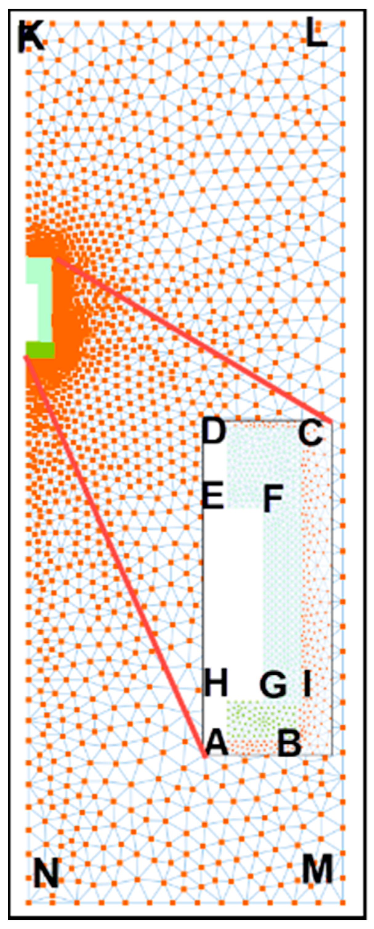
2.1. Model Establishment
2.2. Model Parameter Settings
2.2.1. Ceramic Emitters and Soil Hydraulic Parameters
2.2.2. Boundary and Initial Conditions
3. HYDRUS-2D Model Validity Verification
3.1. Model Verification Experiment
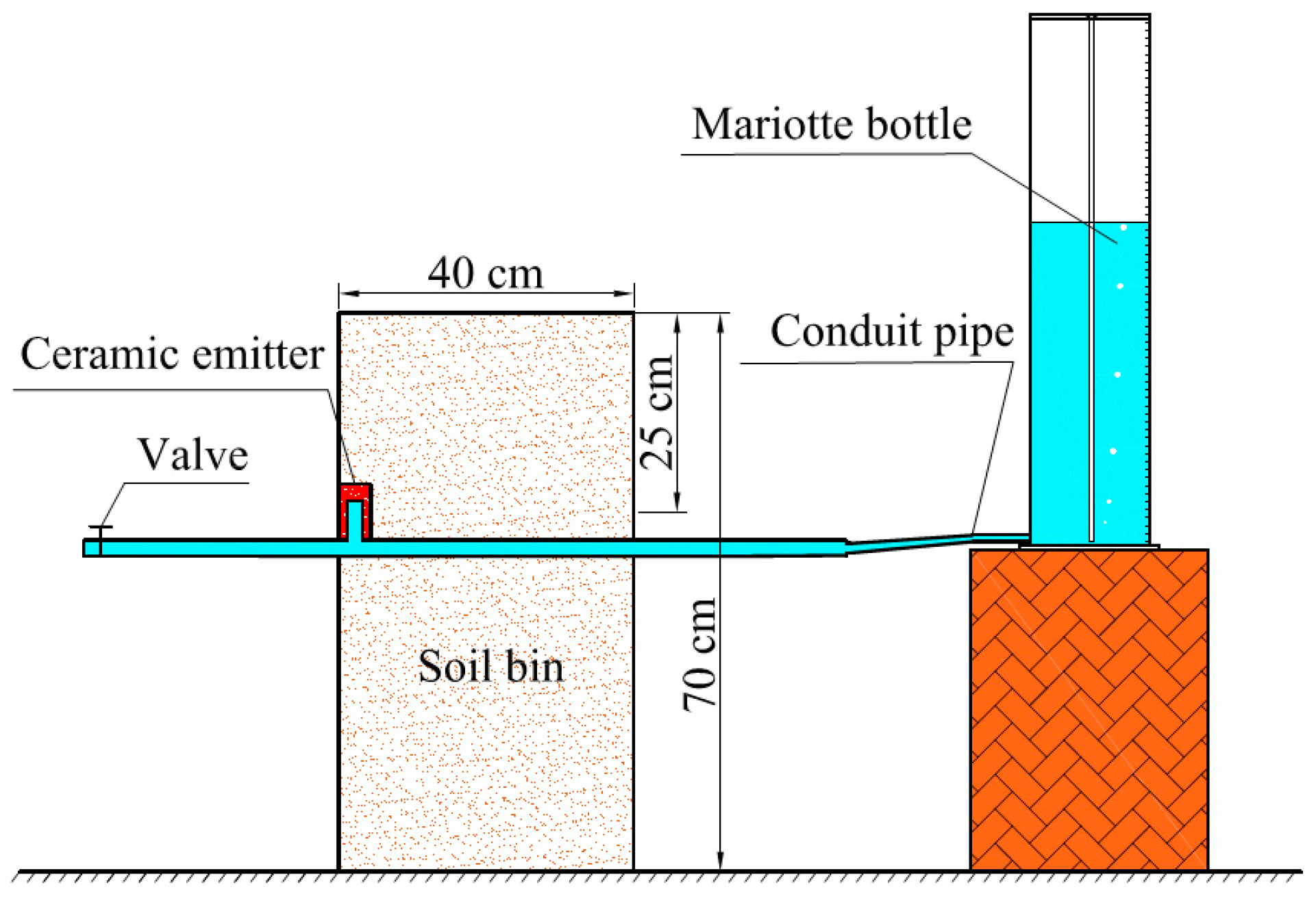
3.1.1. Experiment Setup
3.1.2. Simulation Effectiveness Evaluation
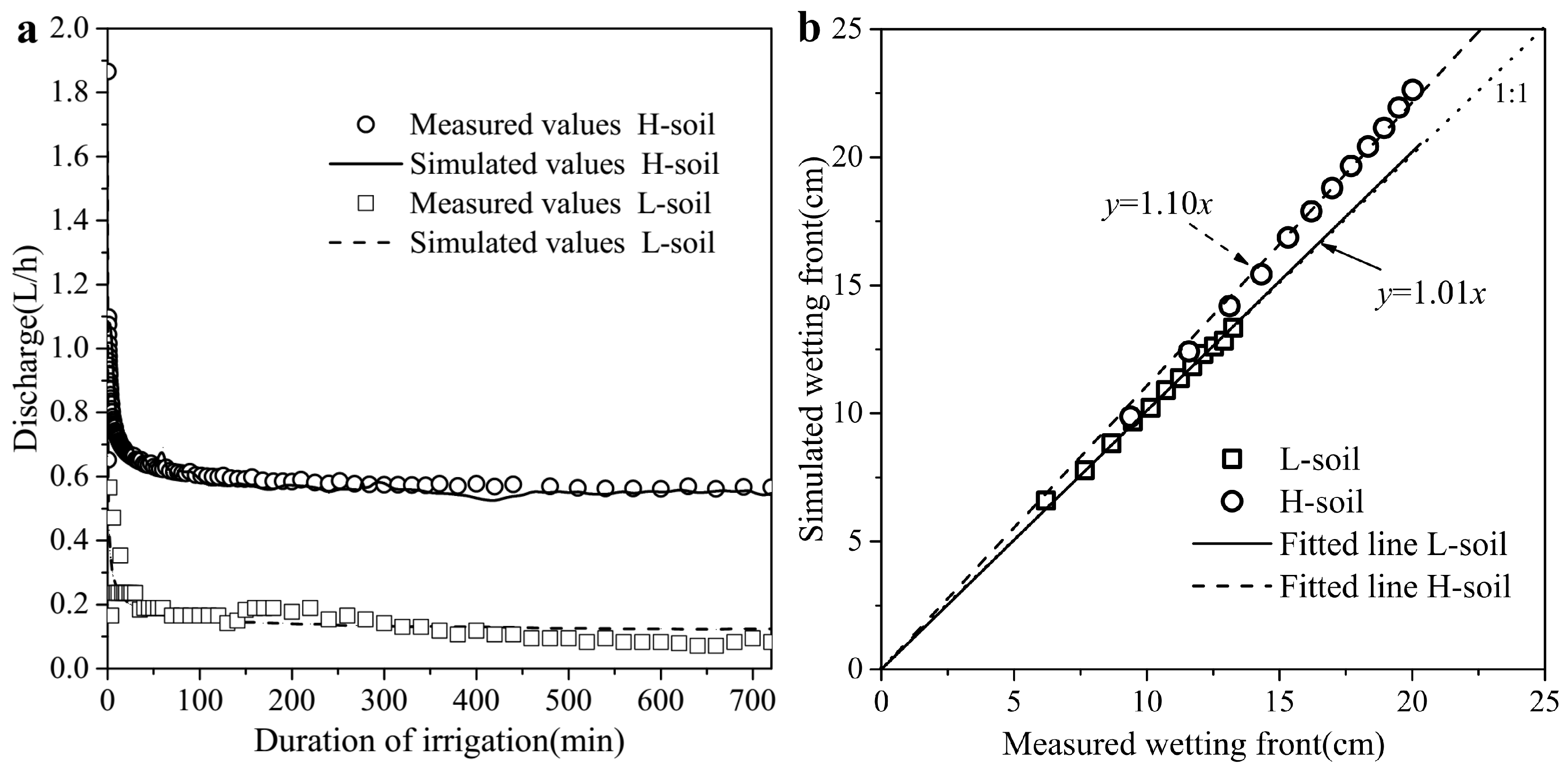
3.2. Model Verification Results
4. HYDRUS-2D Model Application
4.1. Infiltration Characteristics
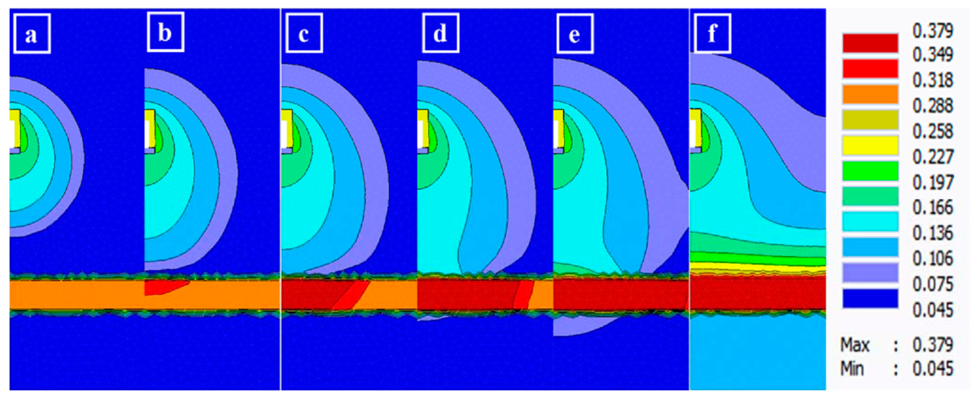
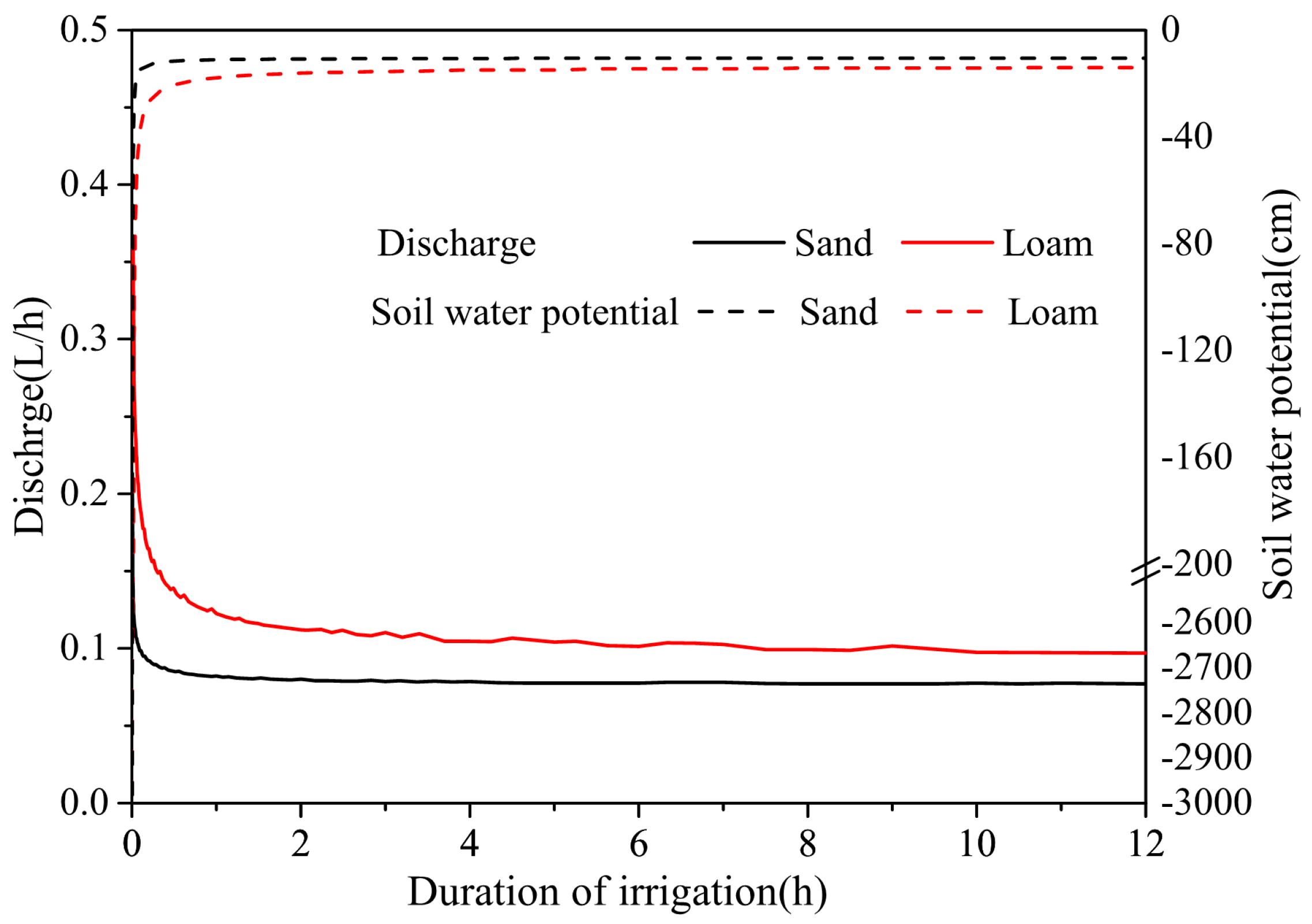
4.1.1. Cumulative Infiltration, Discharge, and Matrix Potential
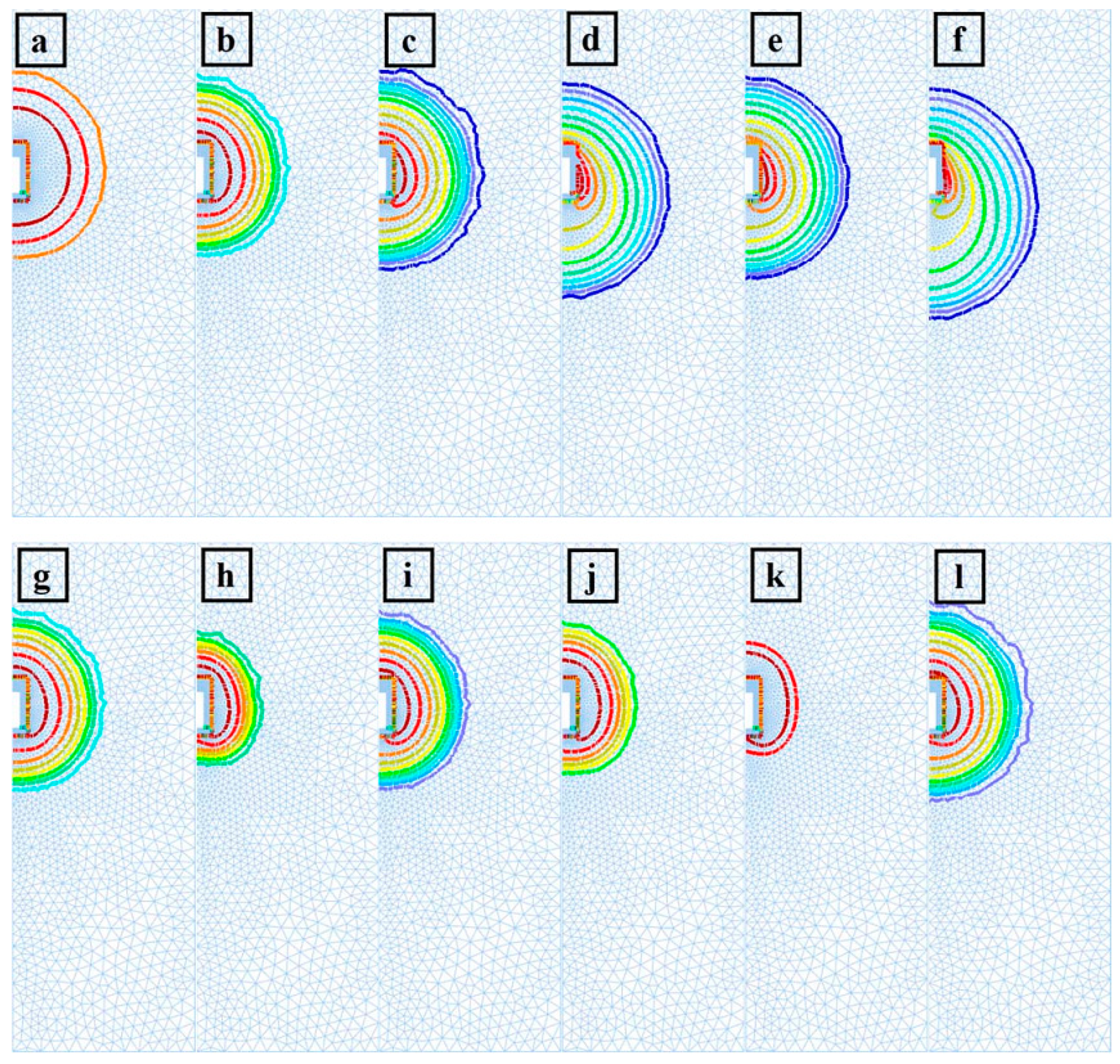
4.1.2. Wetting Front
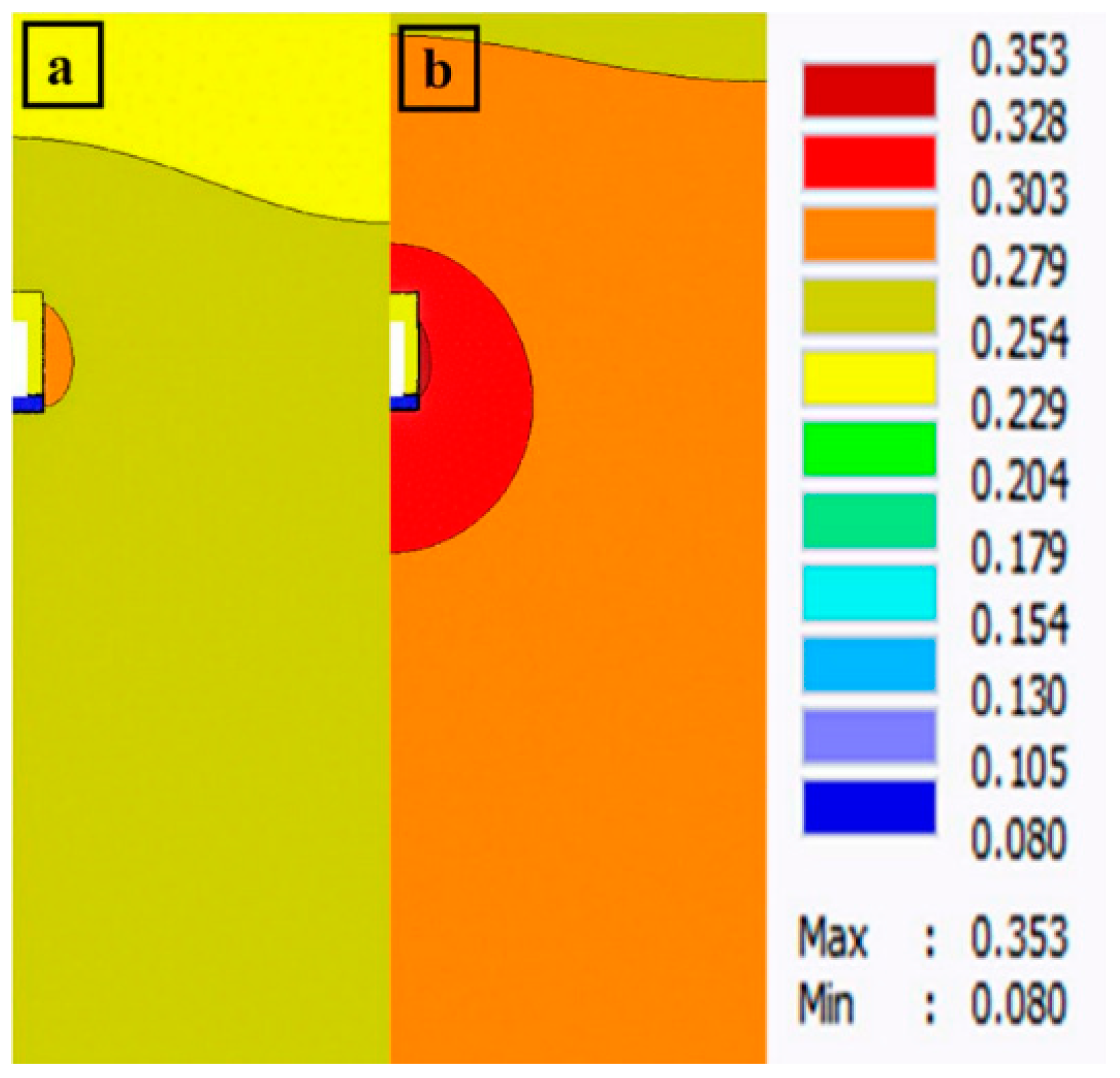
4.2. Optimization Layout of Porous Ceramic Emitters in Sandy Soil
5. Conclusions
Author Contributions
Funding
Conflicts of Interest
References
- Khan, N.N.; Islam, M.; Islam, S.; Moniruzzaman, S.M. Effect of Porous Pipe Characteristics on Soil Wetting Pattern in a Negative Pressure Difference Irrigation System. Am. J. Eng. Res. 2015, 4, 1–12. [Google Scholar]
- Zhang, J.; Saito, H.; Kato, M. Study on Subsurface Irrigation Using Ceramic Pitcher on Tomato Cultivation in Greenhouse. J. Arid Land Stud. 2009, 267, 265–267. [Google Scholar] [CrossRef]
- Cai, Y.; Wu, P.; Zhu, D.; Li, X.; Zhang, L.; Chen, J. Preparation technology optimization of diatomite porous ceramic irrigation emitter. Trans. Chin. Soc. Agric. Eng. 2015, 31, 70–76. [Google Scholar] [CrossRef]
- Cai, Y.; Wu, P.; Zhang, L.; Zhu, D.; Wu, S.; Zhao, X.; Chen, J.; Dong, Z. Prediction of flow characteristics and risk assessment of deep percolation by ceramic emitters in loam. J. Hydrol. 2018, 566, 901–909. [Google Scholar] [CrossRef]
- Siyal, A.A.; Skaggs, T.H. Measured and simulated soil wetting patterns under porous clay pipe sub-surface irrigation. Agric. Water Manag. 2009, 96, 893–904. [Google Scholar] [CrossRef]
- Lamm, R.F.; Ayars, E.J.; Nakayama, S.F. Microirrigation for Crop Production: Design, Operation, and Management; Elsevier: Amsterdam, The Netherlands, 2006. [Google Scholar]
- Wang, J.; Huang, Y.; Long, H.; Hou, S.; Xing, A.; Sun, Z. Simulations of water movement and solute transport through different soil texture configurations under negative-pressure irrigation. Hydrol. Process. 2017, 31, 2599–2612. [Google Scholar] [CrossRef]
- Naik, B.S.; Panda, R.K.; Nayak, S.C.; Sharma, S.D. Hydraulics and salinity profile of pitcher irrigation in saline water condition. Agric. Water Manag. 2008, 95, 1129–1134. [Google Scholar] [CrossRef]
- Hajjaji, M.; Mezouari, H. A calcareous clay from Tamesloht (Al Haouz, Morocco): Properties and thermal transformations. Appl. Clay Sci. 2011, 51, 507–510. [Google Scholar] [CrossRef]
- Das Gupta, A.; Babel, M.S.; Ashrafi, S. Effect of soil texture on the emission characteristics of porous clay pipe for subsurface irrigation. Irrig. Sci. 2009, 27, 201–208. [Google Scholar] [CrossRef]
- Siyal, A.A.; van Genuchten, M.T.; Skaggs, T.H. Solute transport in a loamy soil under subsurface porous clay pipe irrigation. Agric. Water Manag. 2013, 121, 73–80. [Google Scholar] [CrossRef]
- Siyal, A.A.; Van Genuchten, M.T.; Skaggs, T.H. Performance of pitcher irrigation system. Soil Sci. 2009, 174, 312–320. [Google Scholar] [CrossRef]
- Ren, G. Research on Soil Water Movement Characteristics under Microporous Ceramic Emitter Irrigation. Master’s Thesis, Northwest A & F University, Yangling, China, 2016. [Google Scholar]
- Šimůnek, J.; van Genuchten, M.T.; Sejna, M. The HYDRUS Software Package for Simulating the Two- and Three-Dimensional Movement of Water, Heat, and Multiple Solutes in Variably-Saturated Porous Media. Tech. Manual 2012, 230. [Google Scholar] [CrossRef]
- Van Genuchten, M.T. A Closed-form Equation for Predicting the Hydraulic Conductivity of Unsaturated Soils1. Soil Sci. Soc. Am. J. 1980, 44, 892–898. [Google Scholar] [CrossRef]
- Mualem, Y. A new model for predicting the hydraulic conduc. Water Resour. Res. 1976, 12, 513–522. [Google Scholar] [CrossRef]
- USDA. USDA Textural Soil Classification. Soil Mechanics Level I Module 3; United States Department of Agriculture, National Employee Staff, Soil Conservation Service: Washington, DC, USA, 1987.
- Schaap, M.G.; Leij, F.J.; van Genuchten, M.T. Rosetta: A computer program for estimating soil hydraulic parameters with hierarchical pedotransfer functions. J. Hydrol. 2001, 251, 163–176. [Google Scholar] [CrossRef]
- Fan, Y.W.; Huang, N.; Zhang, J.; Zhao, T. Simulation of soil wetting pattern of vertical moistube-irrigation. Water 2018, 10, 601. [Google Scholar] [CrossRef]
- Carsel, R.F.; Parrish, R.S. Developing joint probability descriptions of soil water retention. Water Resour. Res. 1988, 24, 755–769. [Google Scholar] [CrossRef]
- Twarakavi, N.K.C.; Sakai, M.; Šimůnek, J. An objective analysis of the dynamic nature of field capacity. Water Resour. Res. 2009. [Google Scholar] [CrossRef]
- Kacimov, A.R.; Obnosov, Y.V. Tension-saturated and unsaturated flows from line sources in subsurface irrigation: Riesenkampf’s and Philip’s solutions revisited. Water Resour. Res. 2016, 52, 1866–1880. [Google Scholar] [CrossRef]
- Kacimov, A.R.; Obnosov, Y.V.; Šimůnek, J. Steady Flow from an Array of Subsurface Emitters: Kornev’s Irrigation Technology and Kidder’s Free Boundary Problems Revisited. Transp. Porous Media 2018, 121, 643–664. [Google Scholar] [CrossRef]
- Naglič, B.; Kechavarzi, C.; Coulon, F.; Pintar, M. Numerical investigation of the influence of texture, surface drip emitter discharge rate and initial soil moisture condition on wetting pattern size. Irrig. Sci. 2014, 32, 421–436. [Google Scholar] [CrossRef]
- Jury, W.; Horton, R. Soil Physics; John Wilcy & Sons Inc.: Hoboken, NJ, USA, 2004; ISBN 0-471-05965-x(cloth). [Google Scholar]
- El-Nesr, M.N.; Alazba, A.A.; Šimůnek, J. HYDRUS simulations of the effects of dual-drip subsurface irrigation and a physical barrier on water movement and solute transport in soils. Irrig. Sci. 2014, 32, 111–125. [Google Scholar] [CrossRef]
- Trifunovic, B.; Gonzales, H.B.; Ravi, S.; Sharratt, B.S.; Mohanty, S.K. Dynamic effects of biochar concentration and particle size on hydraulic properties of sand. Land Degrad. Dev. 2018, 29, 884–893. [Google Scholar] [CrossRef]
- Zhang, J.; Chen, Q.; You, C. Biochar Effect on Water Evaporation and Hydraulic Conductivity in Sandy Soil. Pedosphere 2016, 26, 265–272. [Google Scholar] [CrossRef]
- Han, D.; Wei, Z.; Yu, J.; Song, R. Influence Mechnisms of Wetting Rate on Soil Saturated Hydraulic Conductivity. J. Soil Water Conserv. 2015, 29, 43–51. [Google Scholar] [CrossRef]
- Han, D. The Study on Effect and Mechanism of Wetting Rate and Chemical Materials on Soil Hydraulic Properties. Ph.D. Thesis, Inner Mongolia Agricultural University, Hohehot Municipality, China, 2016. [Google Scholar]


| Soil Type | θr (cm3 cm−3) | θs (cm3 cm−3) | α (m−1) | N (-) | Ks (cm h−1) | Field Capacity (cm3 cm−3) | Initial Pressure Head h0 (cm) |
|---|---|---|---|---|---|---|---|
| L-Soil | 0.08 | 0.46 | 0.006 | 1.61 | 0.08 | 0.37 | −3000 |
| H-soil | 0.08 | 0.49 | 0.007 | 2.22 | 0.68 | 0.25 | −8562 |
| Statistical Indicators | Discharge | Wetting Front | ||||
|---|---|---|---|---|---|---|
| CRM | RMSE | NRMSE | CRM | RMSE | NRMSE | |
| L-soil | −2.00% | 0.05 | 0.26 | 1.5% | 0.17 | 0.02 |
| H-soil | −0.02% | 0.04 | 0.07 | 9.9% | 1.77 | 0.11 |
| Soil Texture | θr (cm3 cm−3) | θs (cm3 cm−3) | α (m−1) | N (-) | Ks (cm h−1) | Field Capacity (cm3 cm−3) | Initial Pressure Head (cm) |
|---|---|---|---|---|---|---|---|
| Sand | 0.045 | 0.43 | 0.145 | 2.68 | 29.7 | 0.067 | −3000 |
| Loamy Sand | 0.057 | 0.41 | 0.124 | 2.28 | 14.6 | 0.094 | −3000 |
| Sandy Loam | 0.065 | 0.41 | 0.075 | 1.89 | 4.42 | 0.139 | −3000 |
| Loam | 0.078 | 0.43 | 0.036 | 1.56 | 1.04 | 0.220 | −3000 |
| Silt | 0.034 | 0.46 | 0.016 | 1.37 | 0.25 | 0.286 | −3000 |
| Silty Loam | 0.067 | 0.45 | 0.02 | 1.41 | 0.45 | 0.272 | −3000 |
| Sandy Clay Loam | 0.100 | 0.39 | 0.059 | 1.48 | 1.31 | 0.227 | −3000 |
| Clay Loam | 0.095 | 0.41 | 0.019 | 1.31 | 0.26 | 0.295 | −3000 |
| Silty Clay Loam | 0.089 | 0.43 | 0.010 | 1.23 | 0.07 | 0.348 | −3000 |
| Sandy Clay | 0.100 | 0.38 | 0.027 | 1.23 | 0.12 | 0.306 | −3000 |
| Silty Clay | 0.070 | 0.36 | 0.005 | 1.09 | 0.02 | 0.336 | −3000 |
| Clay | 0.068 | 0.38 | 0.008 | 1.09 | 0.2 | 0.34 | −3000 |
| Clay | Clay Loam | Loam | Loamy Sand | Sandy Loam | Sand | Sandy Clay Loam | Sandy Clay | Silt | Silty Clay Loam | Silty Clay | Silty Loam | |
|---|---|---|---|---|---|---|---|---|---|---|---|---|
| Aspect ratio (%) | 97.34 | 94.97 | 97.49 | 125.16 | 108.85 | 148.96 | 97.19 | 93.23 | 95.02 | 94.58 | 83.84 | 96.07 |
| Cumulative infiltration (12 h) (L) | 0.28 | 0.73 | 1.28 | 1.01 | 1.23 | 0.94 | 0.73 | 0.25 | 1.00 | 0.40 | 0.07 | 1.23 |
| Soil Texture | θr (cm3 cm−3) | θs (cm3 cm−3) | α (m−1) | n (-) | Ks (cm h−1) |
|---|---|---|---|---|---|
| Sandy loam | 0.083 | 0.312 | 0.016 | 1.594 | 2.73 |
| PAM-mixed sandy loam | 0.145 | 0.353 | 0.030 | 1.561 | 2.39 |
© 2018 by the authors. Licensee MDPI, Basel, Switzerland. This article is an open access article distributed under the terms and conditions of the Creative Commons Attribution (CC BY) license (http://creativecommons.org/licenses/by/4.0/).
Share and Cite
Cai, Y.; Zhao, X.; Wu, P.; Zhang, L.; Zhu, D.; Chen, J. Effect of Soil Texture on Water Movement of Porous Ceramic Emitters: A Simulation Study. Water 2019, 11, 22. https://doi.org/10.3390/w11010022
Cai Y, Zhao X, Wu P, Zhang L, Zhu D, Chen J. Effect of Soil Texture on Water Movement of Porous Ceramic Emitters: A Simulation Study. Water. 2019; 11(1):22. https://doi.org/10.3390/w11010022
Chicago/Turabian StyleCai, Yaohui, Xiao Zhao, Pute Wu, Lin Zhang, Delan Zhu, and Junying Chen. 2019. "Effect of Soil Texture on Water Movement of Porous Ceramic Emitters: A Simulation Study" Water 11, no. 1: 22. https://doi.org/10.3390/w11010022
APA StyleCai, Y., Zhao, X., Wu, P., Zhang, L., Zhu, D., & Chen, J. (2019). Effect of Soil Texture on Water Movement of Porous Ceramic Emitters: A Simulation Study. Water, 11(1), 22. https://doi.org/10.3390/w11010022