Article

A Simulation-Optimization Model for Seawater Intrusion Management at Pingtung Coastal Area, Taiwan

Institute of Earth Sciences, National Taiwan Ocean University, No. 2, Beining Rd., Jhongjheng District, Keelung City 202, Taiwan
*
Author to whom correspondence should be addressed.
Water 2018, 10(3), 251; https://doi.org/10.3390/w10030251
Submission received: 24 November 2017 / Revised: 22 February 2018 / Accepted: 26 February 2018 / Published: 28 February 2018
(This article belongs to the Special Issue Seawater Intrusion: Simulation and Control)

Abstract

:
The coastal regions of Pingtung Plain in southern Taiwan rely on groundwater as their main source of fresh water for aquaculture, agriculture, domestic, and industrial sectors. The availability of fresh groundwater is threatened by unsustainable groundwater extraction and the over-pumpage leads to the serious problem of seawater intrusion. It is desired to find appropriate management strategies to control groundwater salinity and mitigate seawater intrusion. In this study, a simulation–optimization model has been presented to solve the problem of seawater intrusion along the coastal aquifers in Pingtung Plain and the objective is using injection well barriers and minimizing the total injection rate based on the pre-determined locations of injection barriers. The SEAWAT code is used to simulate the process of seawater intrusion and the surrogate model of artificial neural networks (ANNs) is used to approximate the seawater intrusion (SWI) numerical model to increase the computational efficiency during the optimization process. The heuristic optimization scheme of differential evolution (DE) algorithm is selected to identify the global optimal management solution. Two different management scenarios, one is the injection barriers located along the coast and the other is the injection barrier located at the inland, are considered and the optimized results show that the deployment of injection barriers at the inland is more effective to reduce total dissolved solids (TDS) concentrations and mitigate seawater intrusion than that along the coast. The computational time can be reduced by more than 98% when using ANNs to replace the numerical model and the DE algorithm has been confirmed as a robust optimization scheme to solve groundwater management problems. The proposed framework can identify the most reliable management strategies and provide a reference tool for decision making with regard to seawater intrusion remediation.

1. Introduction

In the 1970s, aquaculture was rapidly developed in the coastal area of Pingtung, Taiwan. To ensure water quality and increase the profit, groundwater was used to supply aquaculture demand in this area. The agricultural, domestic, and industrial sectors also used groundwater to compensate the shortage of surface water due to the uneven distributed rainfall in southern Taiwan. Several decades of groundwater mining without any regulation caused the drawdown of water levels and resulted in consequent seawater intrusion along the coast [1]. Although the pumpage has been monitored and regulated by the government, the total amounts of pumping are still not regulated. The current water levels are similar to the condition in 1999 and recovered insignificantly [2]. Once seawater intrusion occurred, its impact on the shortage of water resources and the distortion of environments has been confirmed [3,4,5]. These threats and the reliance on fresh groundwater resources raise the importance of groundwater management in coastal aquifers to control and mitigate groundwater salinization.
Various strategies have been proposed in the past decades to protect groundwater [6,7,8,9]. No matter what strategies have been selected, one key to control seawater intrusion is to maintain the proper balance between water being pumped from an aquifer and the amount of water recharging it. From this point of view, a management model coupled with a numerical model and optimization approach is desired to remedy seawater intrusion and search for proper strategies of groundwater usage. Physical-based numerical simulation model can be used to examine a limited number of strategy alternatives by trial and error [10,11]. However, the optimization approach can be combined with simulation models to search for the optimal solution in a wide search space of design variables and identify the optimal strategy [12]. The motivation for the combination of simulation and optimization models for seawater intrusion management is its optimal solution, possessing the physical meaning obtained from the numerical model and its searching efficiency for the evaluations of management strategies. The development of the simulation–optimization model, an approach/technique to link the physical-based numerical with the optimization algorithm, can account for the complex behavior of groundwater systems and identify the optimal management strategy by considering appropriate management objective and constraints. The approach has been shown to be capable of handling seawater intrusion in several real-world applications [13,14,15,16].
The physical processes governing seawater intrusion in coastal aquifers are well understood [17]. A calibrated simulation model can help us understanding the behavior of the modeled system and can be applied for different purposes, including the evaluation of aquifer response to different groundwater management strategies. The numerical simulation models used to simulate seawater intrusion can be divided into two categories, sharp-interface and density-dependent models. The sharp-interface models consider freshwater and seawater is immiscible and the Ghyben–Herzberg relationship [18,19] is the most common model [20] which approximates the depth of the sharp-interface between freshwater and seawater. The relationship considers the advection–dispersion processes to define the occurrence of seawater intrusion. Density-dependent models consider the varied-density flow and solute transport resulting from the mixing of freshwater and seawater and the most common used models include SUTRA (A Model for Saturated-Unsaturated,Variable-Density Ground-Water Flow with Solute or Energy Transport) [21], FEMWATER (A Three-Dimensional Finite Element Computer Model for Simulating Density-Dependent Flow and Transport in Variably Saturated Media) [22], and SEAWAT [23]. SEAWAT is developed by USGS based on the integration of MODFLOW (three-dimensional finite-difference ground-water model), MT3DMS (A Modular Three A Modular Three-Dimensional Multispecies Transport Model), and variable-density flow (VDF) package and it can simulate a three-dimensional variable-density groundwater flow coupled with multi-species.
Optimization models are widely used in groundwater planning and management and the aim of optimization is to maximize or minimize an objective function subject to various constraints (e.g., related to regulation of the concentration levels) to protect the water quality of the aquifer. Several studies have shown the optimization approach can be useful in the solution of seawater intrusion management problems [6,13,24]. When solving a seawater intrusion management problem, the objective function is often set to maximize the total pumping rate from several wells while avoiding seawater intrusion into the aquifer or minimize the total injection rate from several injection wells while retreating seawater intrusion front back to the sea [6,25,26]. The constraints restrain the pumping or injection rate between a minimum and a maximum value. As with optimization approaches, the solution can be solved by traditional gradient-based search methods or heuristic algorithms. There exists a large body of literature related to the application of gradient-based search methods in groundwater management problems [27,28,29,30]. However, most optimization techniques are based on evaluating the gradients to locate the optima on given constraints, and the difficulties in evaluating the derivatives and obtaining a good initial value cannot be avoided. To overcome the difficulties resulted from gradient-based search methods, several derivative free optimization algorithms, also called heuristic search algorithms, have emerged [31,32]. Singh [33] provided a comprehensive review about various optimization techniques on seawater intrusion management.
To achieve the effectiveness of simulation-optimization models and to identify the optimal management strategy, integration of simulation and optimization models into a single framework is necessary. The linkage of simulation and optimization models is usually conducted by embedded techniques, i.e., binding the discretized governing equations into the constraints of the optimization model [24,25,29,34] and response matrix methods, i.e., utilizing superposition and linear systems theory to simulate the response of groundwater system to the stimulation of external forcing [27,35,36]. In general, the rate of convergence of response matrix methods is faster than that of embedded techniques [37,38,39,40,41,42]. Singh [33] and Ketabchi and Ataie-Ashtiani [32] also provided a comprehensive review about the integration of simulation and optimization models on seawater intrusion management.
The effectiveness and efficiency of a simulation–optimization model not only rely on the optimization algorithms but also on the computational time of the simulation model. Due to the complexity of physical-based numerical models, solving a simulation–optimization model is sometimes infeasible because the numerical model needs to be run for hundreds to thousands of times during the iteration procedure. To improve the efficiency of simulation–optimization models, a computational efficient surrogate model used to replace the original simulation model is desired. Among plenty of surrogate models, artificial neural networks (ANNs) are the most common approaches used to approximate complex and nonlinear density dependent models. A well trained/tested ANN model can accurately approximate the original model and drastically reduce the computational time when coupled with the optimization algorithm. Johnson and Rogers [43] used ANNs to approximate SUTRA to simulate the domain of volatile organic compounds (VOCs) and the GA was used to solve the multi-objective functions to find the optimal solutions. Bhattacharjya and Datta [44,45] considered the advection–dispersion process to predict saltwater intrusion and implemented the ANNs to substitute such model. Then, the ANNs were combined with GA to find the maximum pumpage volume under a threshold of salinity. Kourakos and Mantoglou [46] used SEAWAT to simulate seawater intrusion and coupled it with evolutionary annealing simplex algorithm to search the optimal pumpage rates. Dhar and Datta [47] used ANNs to approximate seawater intrusion model of FEMWATER and applied Non-dominated Sorting Genetic Algorithm II (NSGA-II) to solve the multi-objective functions. Rao et al. [48] used the ANNs as the surrogate model to replace the SEAWAT model and combined it with the simulated annealing algorithm (SA) to solve the management problems of seawater intrusion. Christelis and Mantoglou [49] used the radial basis functions (RBF) as a surrogate model to emulate the scalar response of a multivariate function which can reduce 96% of computational time and combined RBF with evolutionary annealing-simplex algorithm in a pumping optimization problem.
In the present study, a computational framework for seawater intrusion management in coastal aquifer in Pingtung Plain, Taiwan is presented. The objective of this study is to develop a simulation–optimization model to identify the optimal strategies for the remediation of seawater intrusion. The proposed procedure in this study is similar to Nikolos et al. [50] and Papadopoulou et al. [51], but the key features different from their works are indicated as follows. To increase the computational efficiency of optimization model, MODFLOW-LGR (MODFLOW for Local Grid Refinement) was implemented when developing the physical-based numerical model of SEAWAT. Then, the surrogate model of ANNs was trained and used to approximate SEAWAT model to generate the concentration data. Finally, the ANNs were coupled in the DE algorithm to solve the management problems of seawater intrusion. Two different management scenarios, one was the injection barriers located along the coast and the other was the injection barrier located at the inland, were considered in this study. The management problems were involved in determining the values of optimal injection rates, and subjected to concentration constraints and injection capacities. Different concentration constraints were set to evaluate their effects on the performance of remediation and their associations with the population size setting in the DE algorithm. Under appropriate design and setting of simulation–optimization models, the proposed framework can identify the optimal and most reliable management strategies which can be provided as a reference tool for decision making with regard to seawater intrusion remediation.

2. Methodology

The flowchart of computational framework implemented in this study is shown in Figure 1. The brief descriptions of methods applied in this study including the numerical model of SEAWAT, the surrogate model of ANNs, the general formulation of management model, and the optimization algorithm of DE are introduced as follows.

2.1. SEAWAT

The SEAWAT program, developed by U.S. Geological Survey (USGS), is used to simulate three-dimensional, variable-density transient groundwater flow in porous media [52]. The SEAWAT is developed by combining MODFLOW-2000 [53] and MT3DMS [54] into a single program that solves the coupled flow and solute-transport equations. The general form of the partial differential equation for variable-density groundwater flow is
[ ρ μ 0 μ K 0 ( h 0 + ρ ρ 0 ρ 0 z ) ] = ρ S s , 0 h 0 t + θ ρ C C t ρ s q s '
where ρ is the fluid density (M·L−3), μ 0 is the dynamic viscosity (M·L−1·T−1) at the reference concentration and reference temperature, μ is dynamic viscosity (M·L−1·T−1), K 0 is the hydraulic conductivity tensor saturated with the reference fluid (L·T−1), h 0 is the hydraulic head (L) measured in terms of the reference of a specified concentration, ρ 0 is the fluid density (M·L−3) at the reference concentration and reference temperature, z is the elevation (L), S s , 0 is the specific storage (L−1), t is time (T), θ is porosity (-), C is species concentration (M·L−3), and q s ' is a source or sink (T−1) of fluid with density ρ s . The freshwater is usually used as the reference fluid.
In addition to the groundwater flow equation, a second partial differential equation is required to describe solute transport in the aquifer. The transport of solute mass in groundwater can be described by the following partial differential equation
( 1 + ρ b K d k θ ) ( θ C k ) t = ( θ D C k ) ( q C k ) q s ' C s k
where ρ b is the bulk density (M·L−3), K d k is the distribution coefficient of species k (M·L−3), C k is the concentration of species k (M·L−3), D is the hydrodynamic dispersion coefficient tensor (L2·T−1), q is specific discharge (L·T−1), and C s k is the source or sink concentration (M·L−3) of species k.
For a coupled variable-density flow and solute-transport simulation, fluid density is assumed to be a function of solute concentration only; the effects of pressure and temperature on fluid density are not considered. A linear equation of state is used to represent fluid density as a function of solute concentration:
ρ = ρ f + ρ C C
where ρ f is set to the density of freshwater, and ρ / C is calculated for the range of expected densities and concentrations. Groundwater flow causes the redistribution of solute concentration to alter the density field, thus, affecting groundwater movement. Therefore, the movement of groundwater and transport of solutes in the aquifer are coupled processes, and the two equations must be solved jointly.

2.2 Artificial Neural Networks

Artificial neural networks (ANNs), as the name implies, learn from experience and can perform difficult operations and recognize complex patterns, even if those patterns are noisy. An ANN model is composed of a set of simple elements, called artificial neurons, and these elements are inspired by biological nervous systems. The basic structure of an ANN model is usually comprised of three distinctive layers: (1) the input layer, where data are introduced to the model and computation of the weighted sum of the inputs is performed; (2) the hidden layer(s), where data are processed; and (3) the output layer, where the results of ANN are produced.
In this study, a multilayer perceptron neural network was chosen to model seawater intrusion. The selected network has three layers, i.e., one input layer with varied input variables, one hidden layer with varied nodes, and one output layer with one output variable. Each layer is connected to the proceeding layer by interconnection weights. When an input neuron receives a signal, it is transmitted to the output neuron through the hidden neurons in the hidden layer. The output of a neuron can be expressed as:
y t = f 2 ( j = 1 J ω j k ( 2 ) [ f 1 ( i = 1 I ω i j ( 1 ) x i + b j ) ] + b k )
where x i is the input variable, ω i j ( 1 ) and ω j k ( 2 ) are the interconnection weights between input and hidden layers, and hidden and output layers, respectively. bj and bk are bias values for hidden and output layers, respectively. f 1 ( ) and f 2 ( ) are the activation functions for hidden and output layers, respectively.
The back-propagation algorithm introduced by Rumelhart et al. [55] was selected to train ANNs. The algorithm is akin to the supervised training and modifies the connection intensity to minimize the error of the considered reply. Commonly, the development of ANN model includes the following steps: data collection, data analysis and pre-processing, and training of the neural network. The training of the neural network embraces the choice of architecture, activation functions, training algorithms and parameters of the network, testing of the trained network, and using the trained neural network for simulation and prediction. All these steps are adopted to develop the ANN models in this study.

2.3. Management Model Formulation

In this study, the objective of the management model is to minimize the total injection freshwater from pre-determined injection barriers consisting of different injection wells. The constraints that ensure the mitigation of seawater intrusion are imposed at pre-selected observation locations at the end of 20-year planning horizon. Restrictions for all the injection barriers regarding the maximum allowable injecting rate were also set. The mathematical formulation of the problem is summarized as follows:
min   m = 1 M n = 1 N Q n , m
subject to
C i , T C i max
0 Q n , m Q n , m max
where Q n , m is the injection rate at injection well n belonging to the injection barrier m during the planning horizon; N is the total number of injection wells belonging to the injection barrier m; M is the total number of injection barriers; C i , T is the simulated concentration at monitoring well i at the end of the planning horizon T; C i max is the maximum allowable concentration level (MCL) at monitoring well i; and Q n , m max is the maximum injection capacity at injection well n belong to the injection barrier m.

2.4. Differential Evolution

Differential evolution (DE) algorithm [56], being a recent development in the field of optimization algorithms, is a simply implemented evolutionary algorithm (EA) that has demonstrated better convergence performance than other EAs [57]. The DE algorithm originally designed to deal with the continuous optimization problems of encountered in engineering and environments, and can be easily modified to handle discrete and integer design variables, and multiple constraints. DE has been demonstrated to be one of the most promising novel EAs, in terms of efficiency, effectiveness, and robustness, and these are the reasons for its use in this work [57].
The classic DE algorithm evolves a fixed size population that is randomly initialized. After initializing the population, DE works through a simple iterative process including the mechanisms of mutation, crossover, and selection until a stopping condition is satisfied. Three main control parameters are used in the DE algorithm: the population size, Np, the mutation scaling factor, F, and the crossover rate, Cr. The kernel mechanism in the classical DE algorithm is the mutation strategy and it is defined as follows:
V i , G = X r 1 i , G + F ( X r 2 i , G X r 3 i , G )
where X i , G is a vector of D × 1 variables, and G is the number of iterations. The indices r 1 i , r 2 i , and r 3 i are mutually exclusive integers randomly chosen from the range (1, Np), the scaling factor F is a positive control parameter for scaling the difference vectors. A detailed description of the algorithm used in this work is presented in Karterakis et al. [58] and Chiu [59]. To consider the violation of constraints in the constrained management model, a penalty function is added to the objective function to convert a constrained problem into an unconstrained problem. Then, the added objective function will be abandoned because of the worse performance. The penalty method can be easily handled by DE algorithm.

3. Study Area

3.1. General Background

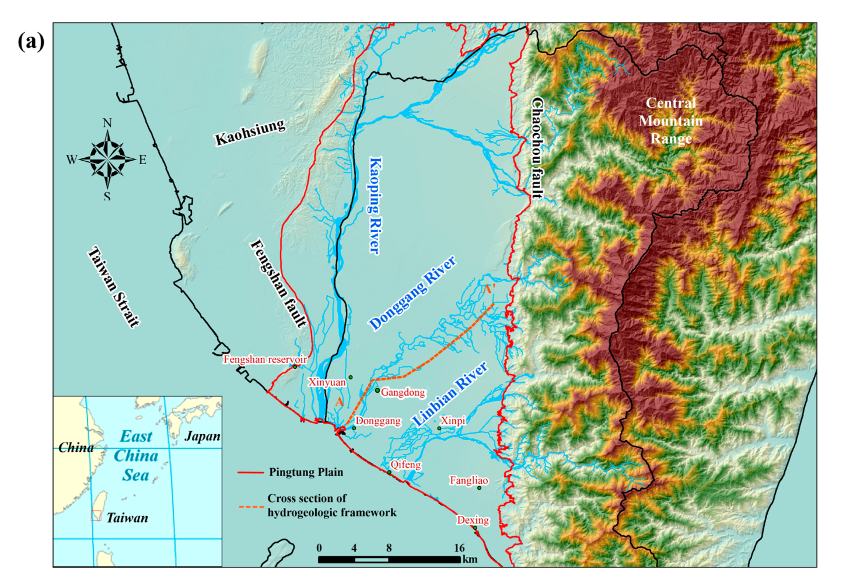
The Pingtung Plain, located in southern Taiwan, is one of the most important aquifers on the island. The elongated plain, with an area of 1210 km2, is roughly 55 km long and 20 km wide. The plain is bounded by the Central Mountain Range to the east, the Taiwan Strait to the southwest, and the low hills to the north and northwest (Figure 2a). The topography of the Pingtung Plain varies from the elevated Central Mountain Range in the east to the gently sloping alluvial fan in the west and southwest. Altitudes range from 10 m above sea level at coastal areas to 110 m above sea level in the mountain range. Streamflow in the Pingtung Plain is perennial and occurs primarily in response to rainfall. The major streams in this area are Kaoping River, Donggang River, and Linbian River and all of them discharge into Taiwan Strait (Figure 2a). The average annual precipitation in the plain is about 2400 mm, but the distribution is uneven during a year, with a ratio of wet season (May to October) to dry season (November to April) of 9:1. Due to uneven distribution of rainfall, surface water supply is usually insufficient and groundwater is used to satisfy the water demand. Accompanying with rapid growth of aquaculture activities in the 1970s and the increase of population along the coastal area, the water supply reliance on groundwater resources is severe and causes groundwater level drawdown very quickly.

3.2. Hydrogeology

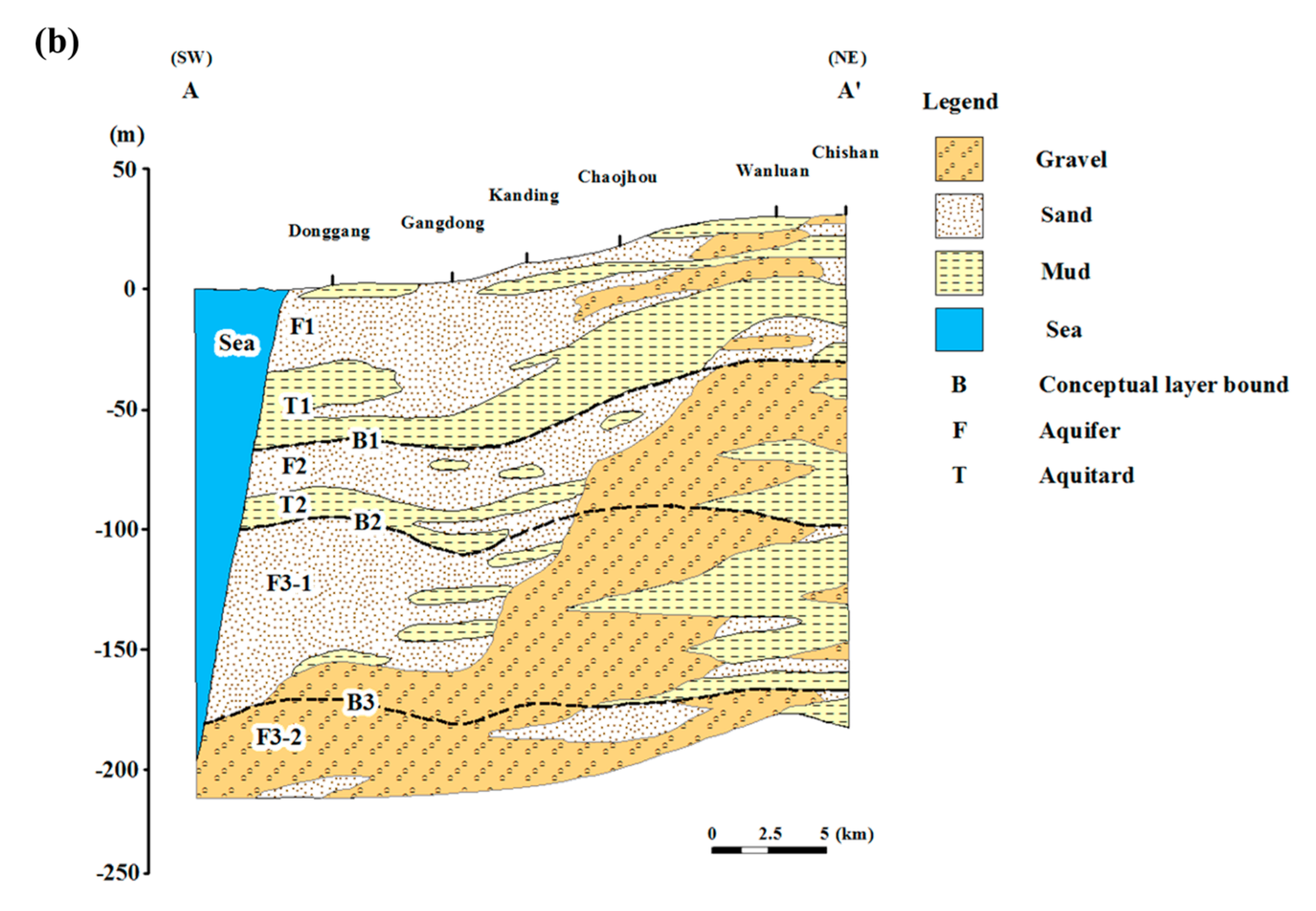
The Pingtung Plain mainly consists of unconsolidated sediments of the late Pleistocene and Holocene period based on the drilling record. Two main active faults, Chaochou and Fengshan faults, are located in the plain and both of them are high-angle and oblique-slip (Figure 2a). Based on lithologic and downhole geophysical logs, the unconsolidated sediments are vertically divided into four aquifers (F) and three aquitards (T). The sequence of the aquifer system is illustrated in Figure 2b and it is referred to as aquifer 1 (F1), aquitard 1 (T1), aquifer 2 (F2), aquitard 2 (T2), aquifer 3-1 (F3-1), aquitard 3 (T3), and aquifer 3-2 (F3-2) along a vertical direction. F1 consists of gravel and fine-to-coarse sand and the thickness is about 50 m. F2 is mainly gravel with occasional fine sand and clay and its thickness is about 60 m. F3-1 consists mainly of gravel and fine-to-coarse sand and it is about 75 m thick. F3-2 also consists mainly of gravel with some sand and clay but the thickness is undetermined because there are no wells fully penetrating this aquifer. T1, T2 and T3, which consist mainly of clay with silt, lie between F1 and F2, F2 and F3-1, and F3-1 and F3-2, respectively.
Estimates of hydraulic conductivity from wells that perforate F1 range from about 0.155 to 364.0 m/day. For the wells that perforate F2 and F3 (F3-1 and F3-2), estimated hydraulic conductivity ranges from 0.365 to 153 m·day−1, and from 0.005 to 120 m·day−1, respectively. Because no wells perforate the aquitards, estimates of hydraulic conductivity in aquitards are based on lithology and range from 8.64 × 10⁻⁵ to 8.64 × 10⁻² m·day−1. Estimates of specific storage in the plain range from 7.15 × 10⁻⁷ to 5.00 × 10⁻⁵ m−1, and estimates of specific yield range from 1.25 × 10⁻⁷ to 3.97 × 10⁻¹ [60]. Regional groundwater flow occurs from northeast to southwest, with an average hydraulic gradient of about 0.002 m·m−1.

3.3. Seawater Intrusion in Pingtung Plain

In the 1970s, aquaculture developed rapidly along the coastal area in Pingtung and the water demand, relying on groundwater resources, increased drastically. The over-pumping seriously caused the water level drawdown and induced seawater intrusion in the coastal aquifer [60]. Due to the constitution of coarse sediments along the coast, the aquifers hydraulically connect to sea and form as the pathway of seawater intruding into the inland. Based on groundwater quality samples and geophysical data, Chiang and Wang [1] delineated the pathway of seawater intrusion and demonstrated that all aquifers F1, F2, F3-1 and F3-2 are connected to the sea and that the most serious areas threatened by seawater intrusion occurred around the estuaries of Kaoping and Donggang rivers. The second most serious areas of seawater intrusion occurred in the shallow aquifer F1 around Fangliao during 1980–1998. Peng et al. [61] found that seawater intrusion was more severe in the deep aquifer than in the shallow aquifer, based on the indication of groundwater quality data. Chiang [62] stated that seawater intrusion fronts in aquifers F1 and F2 moved inland by the rate of 300 m·year−1 and the area of contamination is about 50 km2. The seawater fronts in the deeper aquifers F3-1 and F302 moved into the inland by the rate of 400 m·year−1, faster than those in the shallow aquifers, and the area of contamination is about 100 km2, also larger than that in the shallow aquifers.
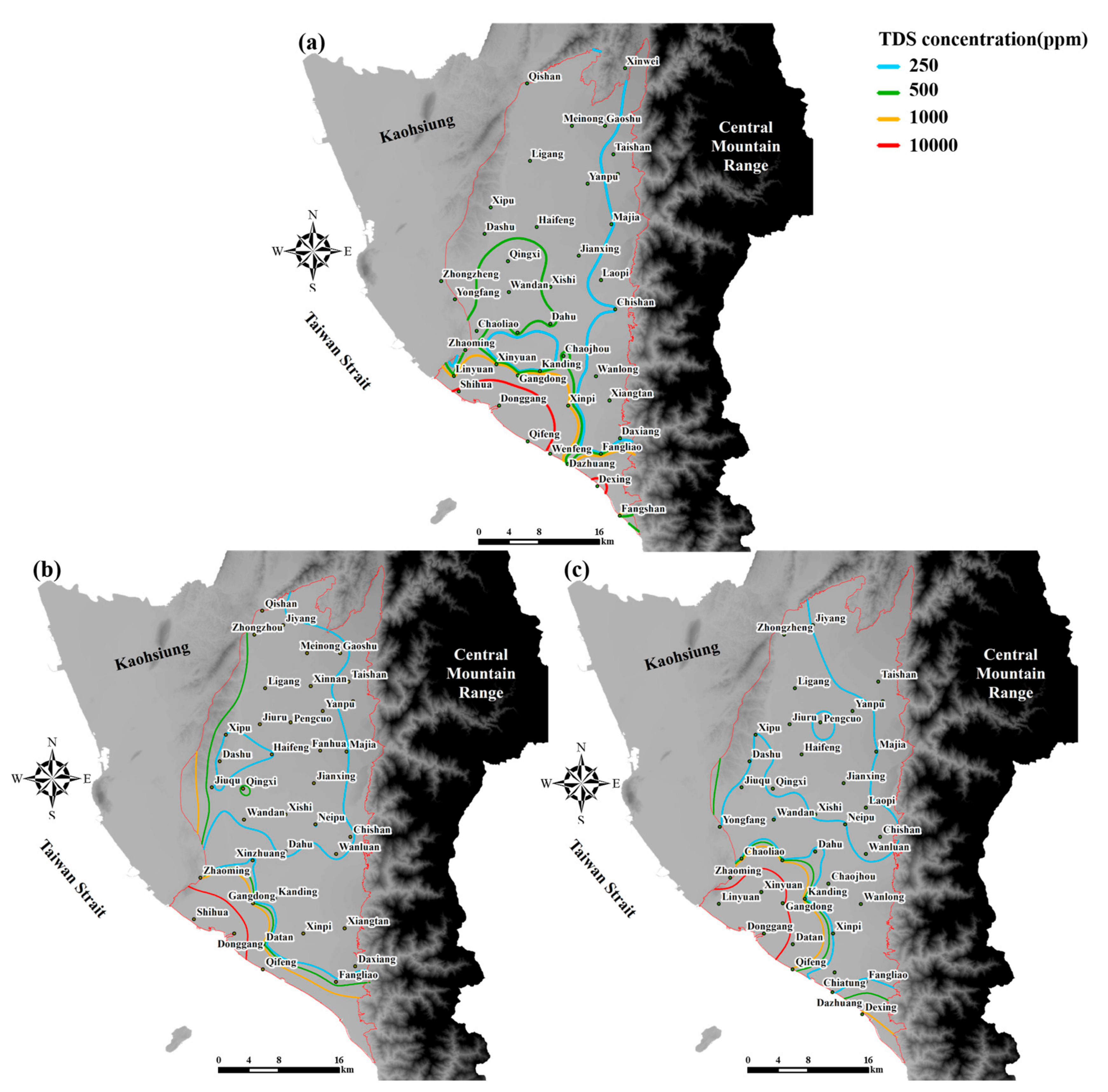
Electric conductivity (EC) data, chloride concentration, and total dissolved solid (TDS) can be used to indicate the occurrence of seawater intrusion and to locate its front. Taiwan Environmental Protection Agency (TWEPA) used the TDS to detect saltwater and classified the quality of the sample water into three categories, i.e., freshwater (TDS < 1000 ppm), semi-brackish water (1000 < TDS < 10,000 ppm), and brackish water (TDS > 10,000 ppm). Based on this classification, Chiang [60] found that all coastal aquifers were contaminated in Pingtung plain where TDS concentrations were greater than 1000 ppm. In aquifer F1, Gangdong and Xinpi were identified as the areas with semi-brackish water, Donggang and Qifeng were identified as the areas with brackish water, and Dexing was identified as the area with slightly contaminated groundwater (Figure 3a). In aquifer F2, the area of contamination was smaller and Donggang was the only area identified as contaminated with brackish water (Figure 3b). In aquifers F3-1 and F3-2, the areas of contamination were the most extensive, and Xinyuan and Gangdong were the areas identified as contaminated with brackish water (Figure 3c).

3.4. Regional Groundwater Flow Model

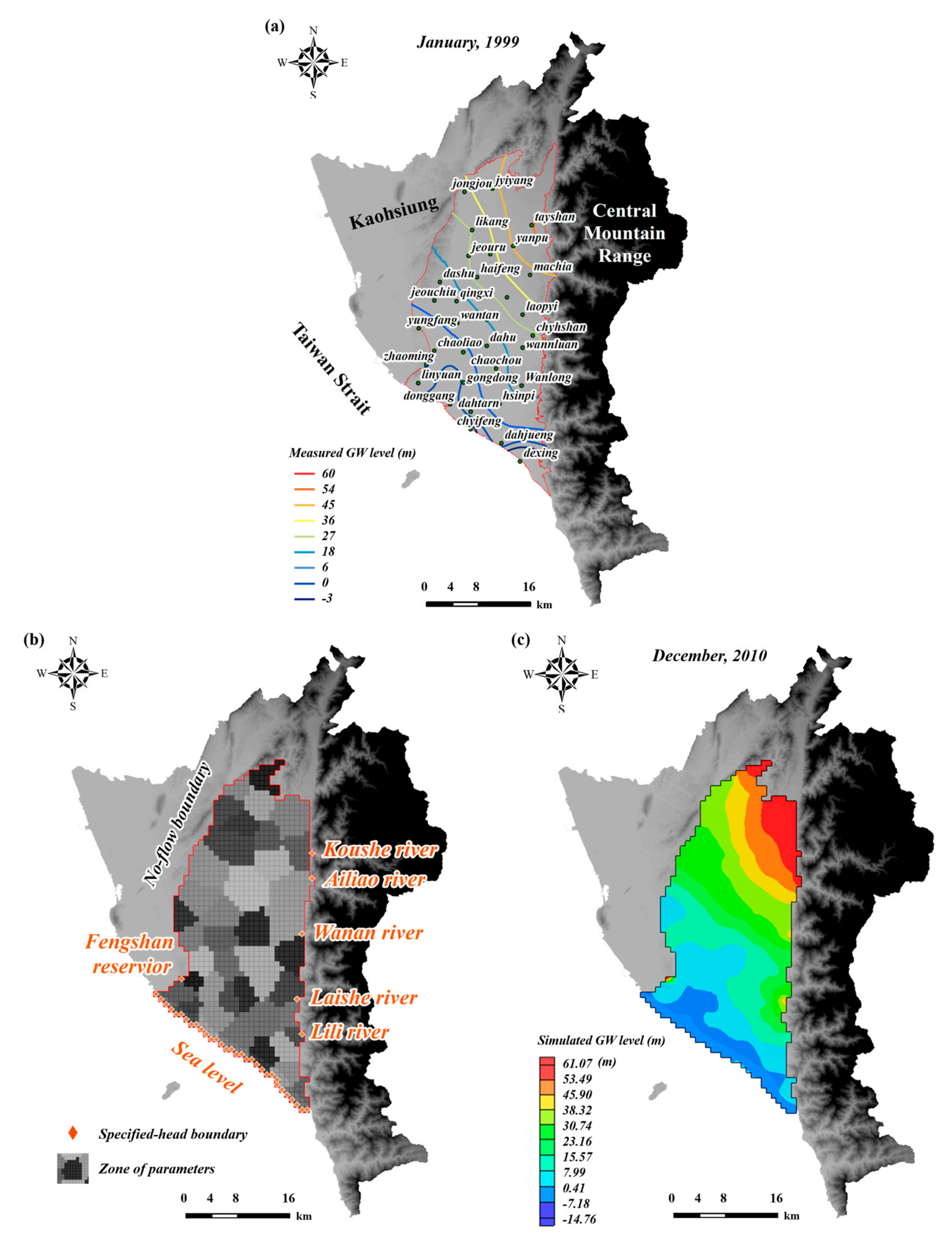
The regional groundwater flow model of Pingtung Plain was developed using MODFLOW-2005. The horizontal discretization consists of 78 rows and 35 columns, and each grid cell is 1000 m × 1000 m. The aquifer system was vertically discretized into five layers: model layers 1 and 3 represent aquifers F1 and F2, model layers 2 and 4 represent the aquitards T1 and T2, and model layer 5 represents aquifer F3-1. Aquifer F3-2 was not included in the numerical model due to insufficient measurements. The horizontal model discretization is shown in Figure 4b. The period of 1999–2010 was simulated and the temporal discretization consisted of one-month stress periods for a total of 144 stress periods using one-week time steps. Monthly stress period was made because only monthly pumping data were available.
The aquifer-system properties for each model layer were assumed to be horizontally isotropic and vertically anisotropic. The initial estimates of these properties, i.e., horizontal hydraulic conductivity, vertical hydraulic conductivity, specific storage, and specific yield were set in the model based on the report [2]. Model layer 1 was set as convertible and the other layers were set as confined. Three types of boundary conditions were used—specified head, specified flux, and head-dependent flux. All lateral model boundaries, except for the southern boundary, were simulated as no-flow boundaries (Figure 4b). Specified-head boundaries were located at the southern border of the model corresponding to the sea and at the eastern border corresponding to the lateral point recharges of rivers. The rainfall recharge was simulated by the recharge package based on the precipitation and estimated infiltration coefficients [63]. The rivers were not included in the model because their interactions with aquifers were insignificant. The water levels in 1999 were set as the initial condition in the model (Figure 4a).
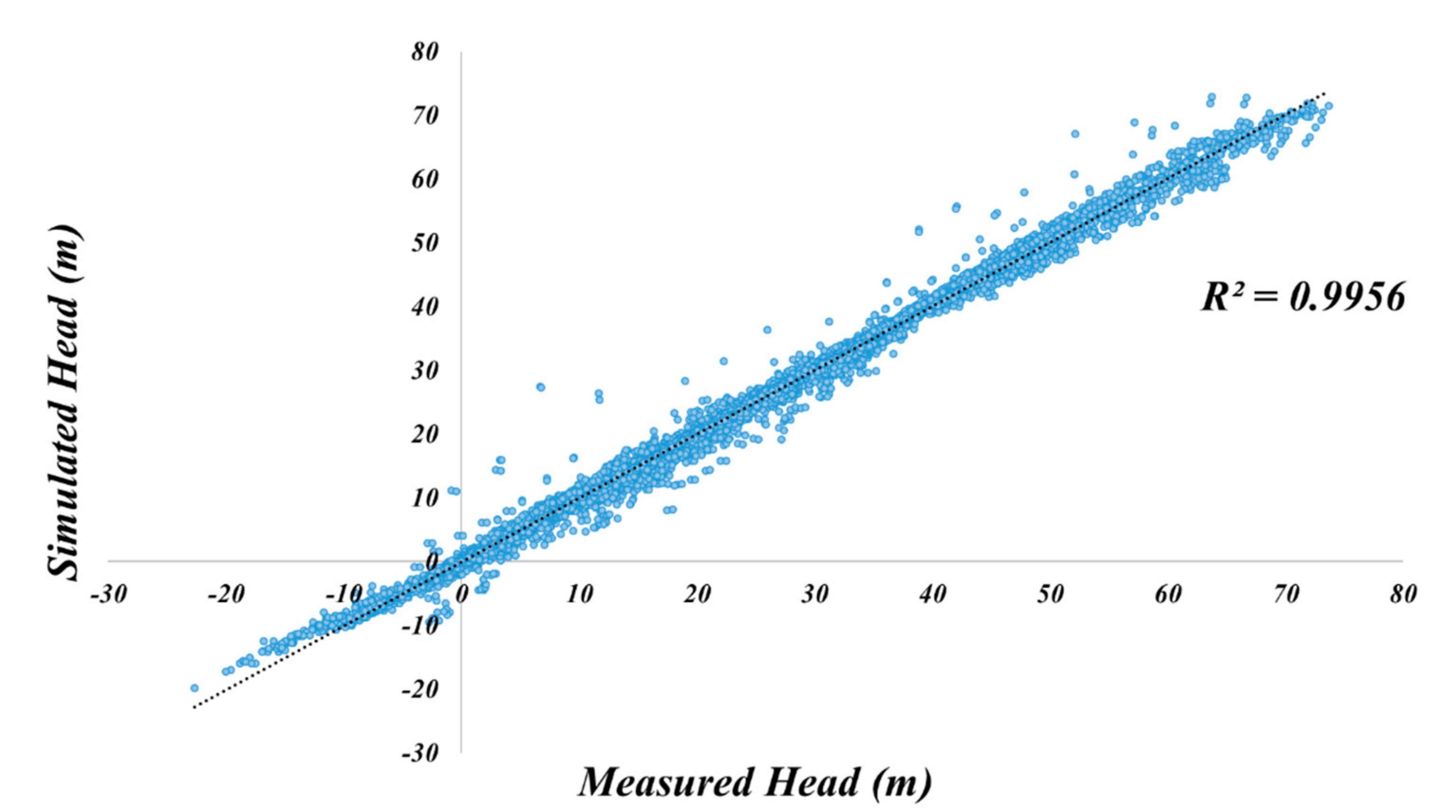
The regional groundwater flow model was calibrated by Chang [2] based on data obtained from single-borehole pumping tests, cross-borehole pumping tests, monitoring wells, and pumpage. The Thiessen polygon was used to parameterize the aquifer properties, i.e., hydraulic conductivity, specific yield, and specific storage (Figure 4b). Due to lack of observation in the aquitards, estimates of hydraulic conductivity in aquitards were based on lithology, ranging from 8.64 × 10⁻⁵–8.64 × 10⁻² m·day−1 [64]. The calibrated parameters are shown in Table 1 and the simulated groundwater levels are shown in Figure 4c. The calibrated regional flow model performed very well (Figure 5) and was adapted for the development of seawater intrusion (SWI) model in this study. The water budget in 1999 obtained from the calibrated regional flow model (Table S1) confirmed that all aquifers were overpumped and the regulation or management might be needed.

4. Results

4.1. Development of the SWI Model

4.1.1. Refinement of Regional Groundwater Flow Model

Although the regional groundwater flow model was well calibrated, its coarse grid cell size is unsuitable for the simulation of seawater intrusion and the model should be refined in both horizontal and vertical directions to accurately represent the process. However, the refinement of entire regional groundwater flow model could extremely increase the number of cells and resulted in impractical computation burden. To overcome the computational challenge and maintain the appropriate boundary conditions simultaneously, MODFLOW-LGR was selected to complete this task [65]. MODFLOW-LGR allows smaller parts of a large model domain to be refined without refining the entire model and inherits the boundary conditions from the original flow model.
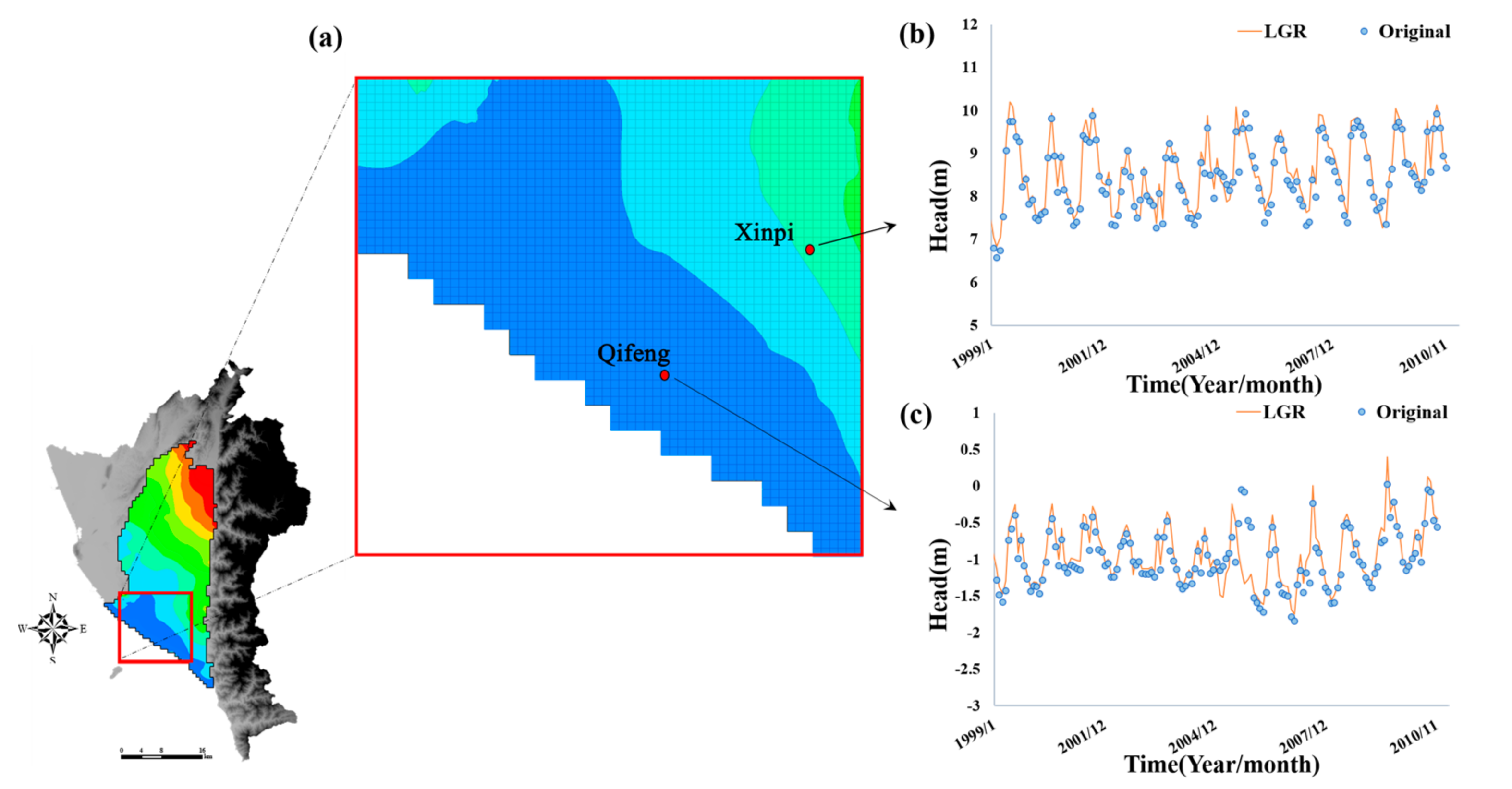
The domain of the refined flow model should cover the areas where seawater intrusion occurred and the TDS was used as the index to delineate these areas. Based on the historical data, the groundwater quality worse than semi-brackish water (TDS > 1000 ppm) was defined as the occurrence of seawater intrusion. The simulated domain for SWI model is decided based on the areas where seawater intrusion occurred, i.e., the red rectangular area shown in Figure 6a. Due to the limitation of MODFLOW-LGR implementation, the shape of refined model is restricted to be a rectangle. Therefore, the process of model refinement was conducted twice to fully cover the entire irregular domain (red rectangular). In the horizontal direction, each cell was subdivided into nine (three in each direction) and the refined grid cell size is 333 m × 333 m. In the vertical direction, each cell was also subdivided into three cells but its thickness depends on the thickness of original cell, which was not a constant. The new refined groundwater flow model consists of 15 layers, 57 rows and 60 columns (the original flow model within the selected domain consists of five layers, 19 rows and 20 columns).
The aquifer properties, i.e., hydraulic conductivity, specific yield, and specific storage, were inherited from the calibrated regional flow model and directly set in the new refined flow model. The pumping and recharge data were adjusted based on the grid cell size and even distributed to each refined cell. The parameters used for building SWI model are shown in Table 1. To confirm the correctness and accuracy of refinement process, the groundwater levels simulated by the refined flow model were compared to those by the regional flow model (Figure 6b,c). The results showed that the groundwater levels obtained from both models were almost identical and the correctness of the procedure has been confirmed. The new generated refined groundwater flow model can not only be used to accurately simulate seawater intrusion process but also to reduce the heavy computational burden.

4.1.2. SWI Model of Pingtung Plain

After obtaining the refined flow model, the SWI model of Pingtung plain was developed by coupling MT3DMS and VDF package with the flow model. In MT3DMS, zero concentration values were specified at the specified head and flux conditions for any inflowing water, except the southern boundary where the TDS concentration was set at 38,500 ppm (approximate to 35,000 ppm salt concentration in seawater). The physical properties that affect mass transport are the retardation factor, the first-order decay term, and hydrodynamic dispersion. Seawater was the only solute considered in this study and adsorption was assumed negligible. Hence, the retardation factor for each layer is equal to 1. Hydrodynamic dispersion, assuming zero molecular diffusion, was a function of dispersivity and average velocity. In this study, an isotropic aquifer is assumed in the horizontal plane and the dispersivity components were determined by longitudinal dispersivity ( α L ), horizontal transverse dispersivity ( α TH ), and vertical transverse dispersivity ( α TV ). The Thiessen polygon used to parameterize the aquifer properties was also used to parameterize the longitudinal dispersivity. The initial values of longitudinal dispersivities ranged from 0.01 to 500 m. The α TH / α L (TRPT) and α TV / α L (TRPT) are set equal to 1.0 and 0.1, respectively. The initial concentrations set for each model cell were interpolated by using the ordinary kriging method based on historical TDS data, either directly measured or indirectly converted from measured electrical conductivities, at each monitoring well between 1999 and 2000 [60,66,67,68].
In the VDF package, the slope, noted as DRHODC ( ρ / C in Equation (3)), is a critical variable used to establish the relationship between density and concentration. The calculated slope of 0.7143 was set in the package based on the assumptions that the densities of seawater and freshwater are 1025 and 1000 (kg·m-3), respectively, and the concentrations of seawater and freshwater are 35.0 and 0.0 (g·L−1), respectively.

4.1.3. Calibration of SWI Model

Once the SWI model was developed, the next step is model calibration. The PEST [69], an automatic parameter estimation software package, was applied to calibrate the mass transport model based on the historical TDS data. The parameter selected to be calibrated was the longitudinal dispersivity.
Due to spatial scarcity of observations within the model domain, i.e., 134 over an area of 379.2 km2, the sensitivity analysis was conducted on the parameters to avoid the problem of over-fitting. Only the parameters with higher sensitivities were selected for calibration and parameters with low sensitivities were fixed at the initial values. The truncated threshold was set based on Hill et al. [70], i.e., those parameters whose sensitivity values are less than about 0.01 times the largest sensitivity value were not estimated. The results of sensitivity analyses and the associated zones of dispersivities with high sensitivities are shown in Figures S1 and S2. Based on results of the analysis, seven dispersivities were selected for calibration and the scatter plot of measured and simulated TDS were shown in Figure 7. The performance of calibration was satisfactory and its coefficient of determination (R2) was about 0.85. The calibrated values of longitudinal dispersivities ranged from 0.01 to 500 m and they are shown in Table 1. Once the SWI model was calibrated, the surrogate model of ANNs can be used to replace the calibrated model through the training and testing processes.

4.2. The Surrogate Model of ANNs

To reduce the computational burden and increase the efficiency of management model, the surrogate model of ANNs was used to replace the SWI model and then embedded in the optimization algorithm. The development of ANNs should be based on the configuration of management model, and two different scenarios for remediation of seawater intrusion were considered in this study.

4.2.1. Management Scenario #1

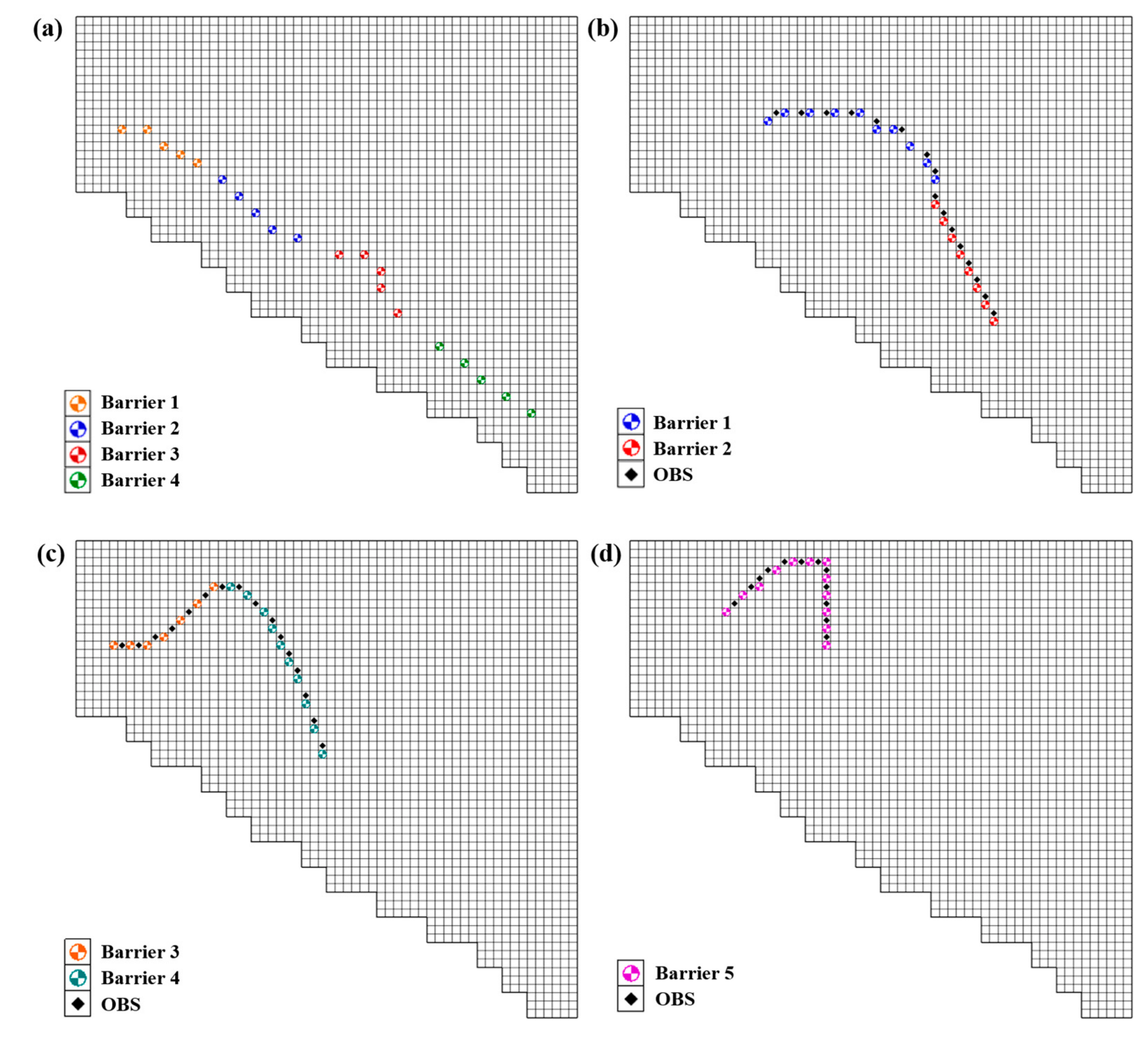
The first management scenario focused on the remediation along the coastal area and tried to shut down the pathway of seawater intrusion. The pre-determined locations of four injection barriers are shown in Figure 8a and fixed during the optimization process. Each barrier consists of five injection wells which were assumed to penetrate through all aquifers, i.e., aquifers F1, F2, and F3-1. The injection rate varied with the barrier but unvaried with time. The locations of concentration constraints coincided with the locations of injection wells and the MCL value set at each location was applied to all three aquifers. Based on this setting, the total number of concentration constraints is equal to 60 (20 locations × 3 layers).
The injection rates at injection wells and the concentrations at the constraint locations were used as the input and output data, respectively. Based on the configuration of management scenario, each different combination of injection rates at four injection barriers corresponded to the simulated concentrations at 60 locations. The number of input and output nodes set in the ANNs were four (injection barriers) and 60 (concentration locations), respectively. The number of discretized pumping rates for each barrier varied from 0 to 1000 m3·day−1 with the interval of 200 m3·day−1 was equal to six (0, 200, 400, 600, 800, and 1000 m3·day−1). Hence, the total combination of different pumping scenarios is equal to 64 (=1296) which means the SWI model needs to run 1296 times to generate all necessary data for the training of ANNs. After determining the architecture of the network, the input and output data were first normalized to an interval between −1 and +1. The activation functions of tangent (tansig) and linear (purelin) functions were used for the hidden and output layers, respectively. The entire dataset was randomly divided into the training, validation, and testing sets by 60%, 20%, and 20% of data, respectively. Two criteria, the convergent gradient which should be less than 10−7 and the maximum epoch which is equal to 1000, were implemented during the ANNs training process. If any one of criteria is met, the training process is terminated. The correlation coefficient (R) for the training, validation, and testing datasets was used to evaluate the performance of identified ANNs.
To prevent overfitting during the ANNs training, 3–9 neurons in the hidden layer from were tested. The mean square error (MSE) was used as the index to evaluate the performances of the potential models with different hidden nodes. The testing results are shown in Table 2 and the optimal number of nodes in the hidden layer is equal to nine. Table 3 and the scatter plot of each dataset (not shown) have confirmed the good performance of identified ANN model for this management scenario.

4.2.2. Management Scenario #2

The second management scenario focused on the inland areas where the concentrations were high and the injection barriers were determined based on the distributions of semi-brackish and brackish waters. According to the historical TDS data, the locations of five injection barriers were deployed and fixed during the optimization process. Two barriers were assigned in each of aquifer F1 (Barriers #1 and #2, Figure 8b) and F2 (Barriers #3 and #4, Figure 8c) and one barrier was assigned in aquifer F3-1 (Barriers #5, Figure 8d). Barriers #1–#5 consisted of 10, 8, 7, 10, and 12 injection wells, respectively, and these wells were assumed to only penetrate the assigned aquifers only. The injection rate also varied with the barrier but unvaried with time. The locations of concentration constraints were set along the high concentration areas in the assigned aquifer, but did not coincide with the injection wells. The number of constraint locations assigned to aquifers F1, F2, and F3-1 were 16, 16 and 12, respectively (Figure 8b–d). The total number of concentration constraints is equal to 44.
Again, the injection rates at injection wells and the concentrations at the constraint locations were used as the input and output data, respectively. Based on the configuration of management scenario, each different combination of injection rates at five injection barriers corresponded to the simulated concentrations at 44 locations. The number of input and output nodes set in the ANNs were five (injection barriers) and 44 (concentration locations), respectively. The number of discretized pumping rates for each barrier varied from 0 to 1000 m3·day−1 with the interval of 250 m3·day−1 was equal to five (0, 250, 500, 750, and 1000 m3·day−1). Hence, the total combination of different pumping scenarios is equal to 55 (=3125) which means the SWI model needs to run 3125 times to generate all necessary data for the training of ANNs. After determining the architecture of the network, the input and output data were first normalized to an interval between −1 and +1 as well. The tangent and linear functions were also used as the activation functions for the hidden and output layers, respectively. The partition of each dataset and the stopping criteria of the training process used in the management Scenario #1 were implemented in this management scenario. The R was also used to evaluate the performance of identified ANNs.
The testing of number of neurons in the hidden layer was neglected, because same SWI model was used for simulation and its characteristics should be very similar. Hence, the tested results from Scenario #1 was applied directly and the number of neurons was set equal to 9. Table 3 and the scatter plot of each dataset (not shown) have confirmed the good performance of identified ANN model for the management Scenario #2.
After completing the training processes of two ANNs models for two different management scenarios, the computational time for each model has been tested and compared based on a PC with inter Core i7 1.3GHz and 8GB RAM. A forward run of numerical model took about six to seven minutes, but a forward simulation of ANNs took only three to four seconds. The computational burden can be reduced by more than 98%. The reduction of computational time by using ANN as the surrogate model to replace the numerical model shows a great advantage in the simulation–optimization (S/O) approach. When conducting the linkage between the optimization algorithm and the complex numerical model, which is the case in this study, this advantage makes the implementation of S/O approach more practical and feasible.

4.3. Results of SWI Management

In this study, the DE algorithm was selected as the optimization algorithm to solve the management model. The well trained ANNs was used to replace the SWI model and embedded in the DE algorithm. The DE codes in MATLAB (Version R2013a, MathWorks, Natick, MA, USA) [56] were adopted.

4.3.1. The Setting of DE Algorithm

To implement DE algorithm for seawater intrusion management, the injection rate at each well belonging to the same barrier was varied simultaneously and considered as the decision variable. The number of decision variables depends on the number of barriers configured in management model, i.e., four and five for the management Scenarios #1 and #2, respectively. The maximum injection capacity for all wells were the same and set equal to 1000 m3·day−1 corresponding to the training process of ANNs. The initial injection rate was randomly generated by the DE algorithm. The convergence criterion of objective function was set equal to 10−6 and the maximum generation is 200.
Before solving the management problem of seawater intrusion, three control parameters, Np, F, and Cr implemented in the DE are tested to find the most efficient and robust setting. After trial and error, Np, F, and Cr were set equal to 30–100, 0.85, and 1, respectively, for both scenarios. The setting of DE algorithm is summarized in Table 4. The concentration constraints were attacked by the penalty method. It is accomplished by adding a term to the objective function that prescribes a high cost for violation of the constraints. The penalty method has already been included in the DE codes in MATLAB and can be easily handled.

4.3.2. The Results of Status Quo

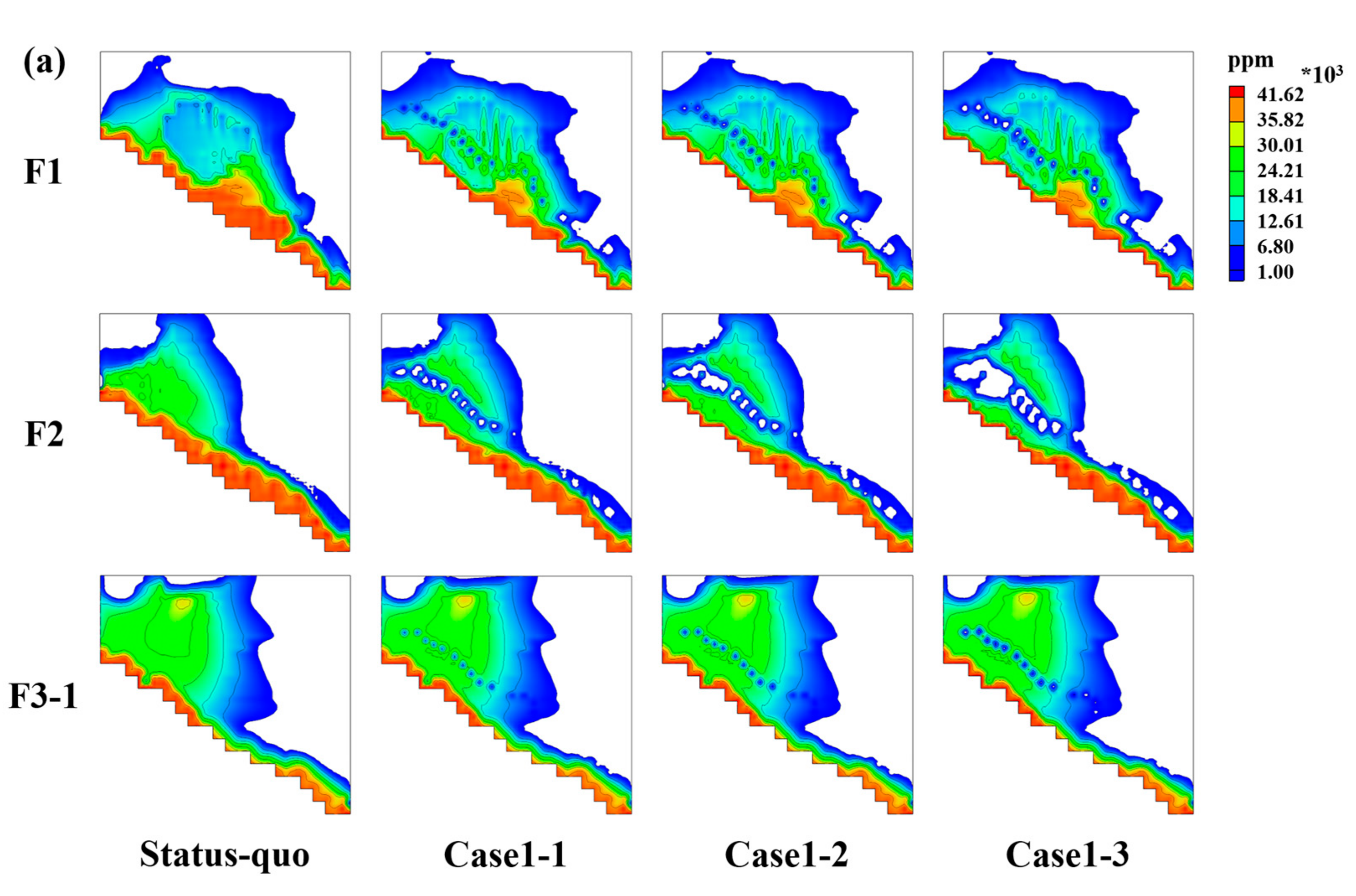
To evaluate the effectiveness of management strategies obtained from Scenarios #1 and #2, the status quo without any actions was simulated for the comparison. The last year of calibrated SWI model were repeatedly simulated for 20 years by using the precipitation, recharge, and pumping data from the last year and the results are shown in the first column of Figure 9a. The figure showed that seawater intrusion becomes more serious and the areas covered by seawater enlarge in aquifer F1. In aquifer F2, TDS concentrations along the coastal areas, especially in Qifeng area, significantly increased from 500 to 34,000 ppm after 20 years. In aquifer F3-1, although the concentrations at Xinyuan (at the northwest of model) decreased slightly caused by the high recharge rate, values still maintained at the high levels, ranging 28,000–31,000 ppm. According to this result, the potential management strategies should be identified and then conducted to control and mitigate the salinization of groundwater aquifers.

4.3.3. The Management Results of Scenario #1

For the first scenario, the remediation strategies focused on the areas along the coastal area and the injection barriers was used to prevent further seawater intrusion. Different setting of MCLs were considered in the management model to provide alternatives for decision making of seawater intrusion remediation. The values of MCL were set equal to 5000, 3000, and 1000 ppm at the end of planning horizon, i.e., 20 years, noted as Cases 1-1, 1-2, and 1-3, respectively. In each case, the population sizes of 30, 50, and 100 were tested and each population size was run six times to ensure the optimal solution was identified. Regarding violation of concentration constraints, a penalty term with a high cost value was added to the objective function.
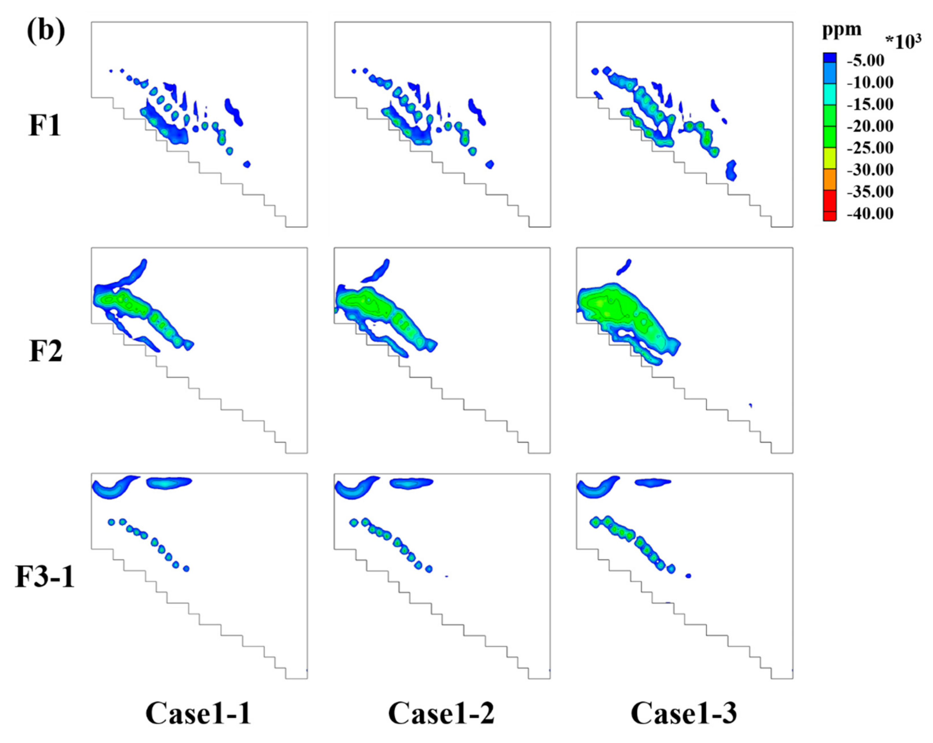
In Case 1-1 (MCL = 5000 ppm), the objective function values obtained from different population size were very similar and the optimal result was identified by using the population size of 30. The minimized objective function value was equal to 4840.15 m3·day−1, and the Barriers #3 and #4 has the lowest and highest injection rates, respectively. The second column in Figure 9a showed the simulated concentrations after 20-year of remediation using the optimal injection strategy. The difference of concentrations between 20-year of remediation and the initial condition was shown in the first column of Figure 9b to demonstrate the effectiveness of remediation. A significant reduction of TDS concentrations was observed around the injection wells. In aquifer F1, the concentrations around Donggang decreased significantly from 32,780 ppm to 14,385 ppm but those around Qifeng still maintained at the high level with 32,766 ppm. In aquifer F2, the injection barriers worked well along the coastal areas where the high concentrations were extensively mitigated from 28,626 ppm to 6621 ppm. In aquifer F3-1, the injection strategy seemed ineffective and the plume with high concentrations still covered large areas, especially around the inland. During the optimization process, the concentration constraints were never violated and implied that the setting of MCL value was too high and could be achieved easily. Consequently, the injection strategy was less effective. To improve the effectiveness of remediation, either a more rigorous concentration constraint should be set or the planning horizon of remediation should be extended to achieve the ultimate target of converting brackish water into freshwater.
In Case 1-2, a more rigorous MCL (=3000 ppm) was set and the minimal objective function values obtained using the population size of 30 was equal to 6415.30 m3·day−1. Barriers #3 and #4 still have the lowest and highest injection rates, respectively. The third column in Figure 9a showed the simulated concentrations after 20-year of remediation using the optimal injection strategy. The difference of concentrations between 20-year of remediation and the initial condition was shown in the second column of Figure 9b to demonstrate the effectiveness of remediation. The effectiveness of remediation was very similar to Case 1-1. In general, a significant decrease of TDS concentrations was observed around the injection wells. The injection barriers performed well around Donggang in aquifer F1 and along coastal areas in aquifer F2. However, the effectiveness of injection strategy on Qifeng area in aquifer F1 and entire aquifer F3-1 was still poor. In Case 1-3, the most rigorous MCL (=1000 ppm) was set and the minimal objective function values obtained using the population size of 100 was equal to 9,825.00 m3·day−1. The forth column in Figure 9a and third in Figure 9b showed the simulated concentrations and concentration difference after 20-year of remediation, respectively. The results were also similar to Cases 1-1 and 1-2. The effectiveness of injection strategy on the Donggang area in aquifer F1 and coastal areas in aquifer F2 slightly increased, but, for the Qifeng area in aquifer F1 (from 37,206 ppm to 27,219 ppm) and entire aquifer F3-1, it almost did not change and remained with high concentration. The optimal results are summarized in Table 5.
From Cases 1-1 to 1-3, it was observed that when a more rigorous constraint was set, the remedied areas in aquifers F1 and F2 only slightly increased but the associated costs significantly increase. The optimal injection strategies have little effect on aquifer F3-1. Overall, the marginal benefit corresponding to the remedied areas seems not to increase with the cost in terms of injection rates. A low concentration (<1000 ppm) area located at the northwest in aquifer F3-1 was observed in all cases. This area was far away from the injection barriers and should not be affected by any management actions. Hence, the low concentrations might be caused by the recharge of Fengshan reservoir. Barrier #4 has the highest injection rate among all barriers because its location was closest to the coastal and coincided with the high concentration brackish water. Barrier #3 has the lowest injection rate among all barriers because it was located at the areas with higher hydraulic conductivities and the concentration constraints could be satisfied easier. None of barriers in all cases could remedy seawater intrusion in aquifer F3-1 and this result implied that the arrangement of injection barriers should be reconsidered.
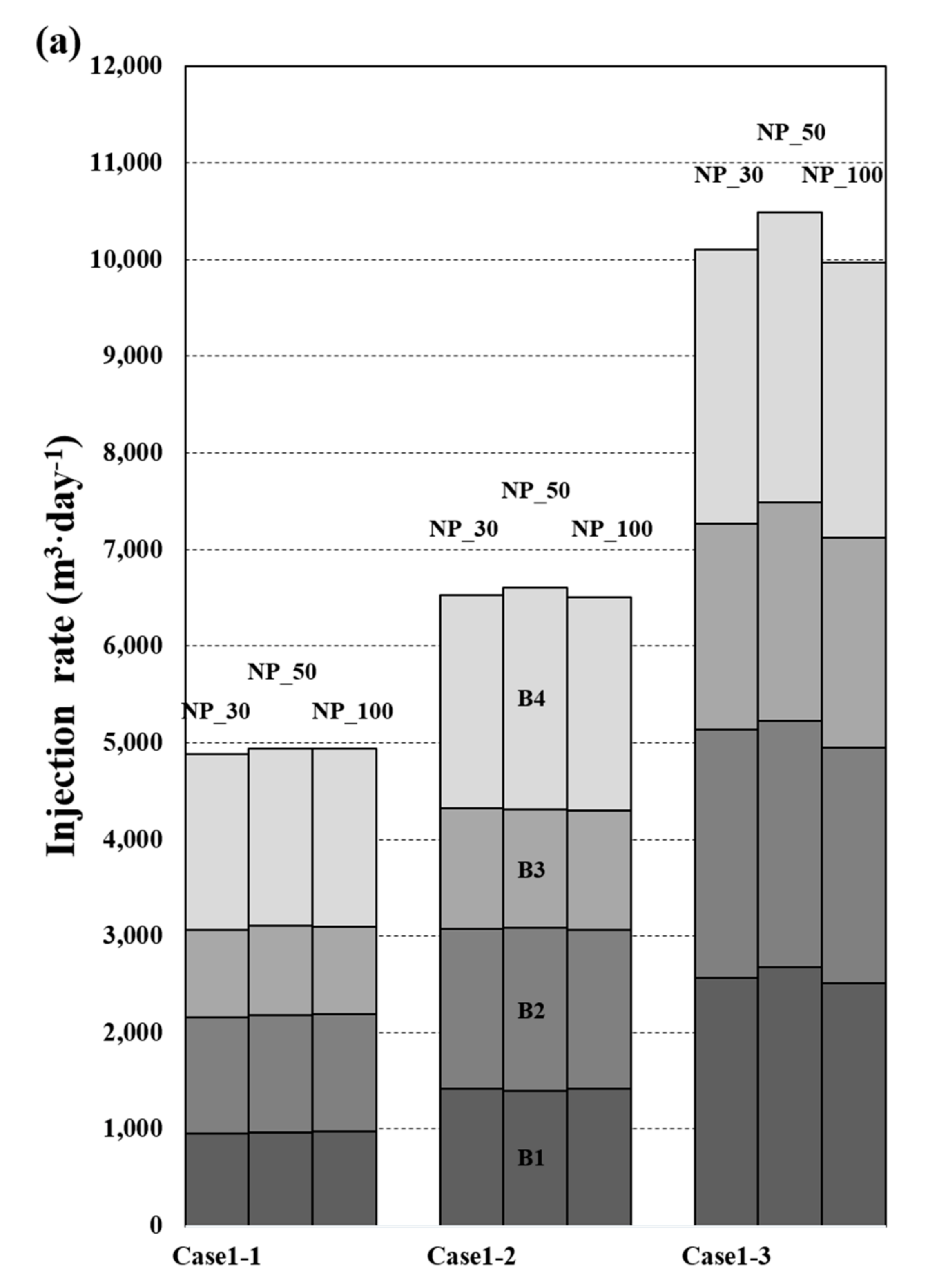
To verify the robustness of DE algorithm, the identified results from six times of repeated optimization processes for each different population size were averaged. The results are shown in Figure 10 for comparison. In each case, although the averaged objective function values obtained from different population sizes were slightly different, their associated injection rates were very similar in terms of the trend and magnitude. This result confirmed the robustness of DE algorithm and can be applied to solve the nonlinear optimization model. In general, the population size should be increased with the setting of more rigorous constraints to extend the search domain and enlarge the probability of identifying the optimal solutions. However, the large population size, i.e., 100 in this scenario, did not guarantee to identify the optimal injection strategy because of the relative relaxation of concentration constraints. When the population size increases, the associated computational time and the iterations needed for convergence also increase. Hence, the trade-off between computational efficiency and optimal solution should be considered when using the heuristic algorithms to solve the optimization problems.
In this scenario, the injection wells were set along the coastal areas and coincided with the locations of concentration constraints. Although the high concentrations can be remedied and seawater intruded from the sea can be alleviated, the radii of influence for the injection wells (barriers) were limited to the small areas due to the groundwater flow directions and the high concentrations located at the inland cannot be mitigated. Hence, the configuration of management scenario should be adjusted to improve its effectiveness by reducing the areas with high concentrations as large as possible. The locations of injection barriers should be shifted from the coastal areas toward the inland and the penetrated depth of each well (barrier) should be designed based on the occurrence of seawater intrusion. The locations of concentration constraints should not be located at the same locations of injection wells.

4.3.4. The Management Results of Scenario #2

For the second scenario, the remediation strategies focused on the inland with high concentrations and the injection barriers were deployed according to the occurrences of seawater intrusion in each aquifer. Different setting of MCLs were also considered in the management model to provide alternatives for decision making of seawater intrusion remediation. The value of MCL was set equal to 15%, 30%, and 50% of reductions of initial concentrations at the end of the planning horizon, i.e., 20 years, noted as Case 2-1, 2-2, and 2-3, respectively. The reason of using percentages of reduction of initial concentrations instead of the absolute values set in Scenario #1 is to evaluate the effect of different constraints on the performance of remediation. As for Scenario #1, the DE algorithm was run six times with different population sizes of 30, 50, and 100 in each case. The violation of concentration constraints was also handled by the penalty term.
In Case 2-1, the objective function values obtained from different population size were very similar, and the optimal result was equal to 5,446.64 m3·day−1 identified by using the population size of 50. Barriers #1 and #4 have the highest and second highest injection rates, respectively, and Barriers #2 and #3 were inactivated. This result implied that Barriers #2 and #3 might be unnecessary and 15% concentration reduction at the constraint locations can be accomplished by natural recharge. The second column in Figure 11a shows concentrations after 20-year of remediation using the optimal injection strategy. The difference of concentrations 20-year of remediation and the initial condition is also shown in the first column of Figure 11b to demonstrate the effectiveness of remediation. In aquifers F1 and F2, the significant reduction of TDS concentrations was not only around the injection wells, but also extended to the downstream gradient of groundwater. In aquifer F1, the concentrations at the entire downstream gradient of injection barriers were mitigated significantly. In aquifer F2, the concentration around Linyuan also decreased obviously from 24,465 ppm to 13,463 ppm. However, in aquifer F3-1, the radii of influence for the injection wells were still limited to the areas nearby and the injection strategy could not effectively remedy seawater intrusion at the deep aquifer.
In Case 2-2, a more rigorous MCL (30% of concentration reduction) was set and the minimal objective function values obtained using the population size of 100 was equal to 12,964.55 m3·day−1. Barrier #4 has the highest injection rate and the most significant increase of injection rate among all barrier compared to Case 2-1. Barriers #2 and #3 were both activated due to the tighter concentration constraints. The third column in Figure 11a and second in 11b showed the simulated concentrations and concentration difference after 20-year of remediation, respectively. In general, the effectiveness of injection strategy was very similar to Case 2-1. The reduction of concentrations around the injection wells and their extents to downstream gradient of groundwater was significant; however, the remediation in aquifer F3-1 was still not very successful. In Case 2-3, the most rigorous MCL (50% of concentration reduction) was set and the minimum objective function values obtained using the population size of 100 was equal to 26,076.5 m3·day−1. All of barriers increased their injection rates evidently to satisfy the tightest concentration constraints. The barriers in aquifer F1 have the highest and second highest injection rates, and the Barrier #2 has the most significant increase of injection rate among all barriers compared to Case 2-2. Barrier #3 has the lowest highest injection rates. The fourth column in Figure 11a and third column in Figure 11b show the simulated concentrations and concentration difference after 20-year of remediation, respectively. Compared to Case 2-2, the high concentrations around Xinpi in aquifer F1 were effectively reduced from 19,503 ppm to 645 ppm due to the highest injection rate of Barrier #2. In aquifer F2, a slight increase of remedied areas was observed and its effectiveness of injection strategy was similar to Case 2-2. Again, the remediation of aquifer F3-1 was still limited to the small areas around the wells. The optimal results are summarized in Table 5.
From Cases 2-1 to 2-3, it was observed that, when a more rigorous constraint was set, the remedied areas in aquifers F1 and F2 could significantly increase associated with the increase of injection rates (costs). However, the optimal injection strategies still have little effect on the remediation of aquifer F3-1. A low concentration area located at the northwest in aquifer F3-1 was also observed in all cases and should be caused by the recharge of Fengshan reservoir. Barriers #1, #4, and #5 can be interpreted as the base injectors to meet the target concentration levels and Barriers #2 and #3 can be interpreted as supplementary injectors to satisfy the extra requirement when the concentration constraints become tighter. Although the deployment of injection barriers was still not perfect, the effectiveness of injection strategy has been improved compared to Scenario #1. The purposes of removing high concentrations located at the inland and increasing the remedied areas in each aquifer were partially achieved.
The identified results from six times of repeated optimization processes for each different population size were also averaged to verify the robustness of DE algorithm. The results are shown in Figure 12 for comparison. In general, the averaged objective function values obtained from different population sizes were different and their associated injection rates were also slightly different. In Case 2-1, the averaged value identified by using the population size of 30 (6398.21 m3·day−1) was higher than that identified by using the population sizes of 50 and 100 (5,462.34 and 5,446.64 m3·day−1). In both Cases 2-2 and 2-3, the lowest averaged values were identified by using the population size of 100. This result indicated that the small population size, i.e., 30, probably has the difficulty to solve a more complicated problem, i.e., more rigorous constraints or more number of decision variables. In this scenario, the number of decision variables was increased by one and the population size should be set large enough, i.e., 100, to obtain a robust solution. The increase of population size could increase the search domain and enlarge the probability of identifying the optimal solutions. Again, the large population size does not guarantee to find the optimal management strategy but a more robust solution can be identified by increasing the population size.
Except the effectiveness of each management scenario on seawater remediation, the performance in terms of the cost was qualitatively evaluated. The installation cost of a well was assumed to dominate the entire total cost (installation and pumping costs) and equal for each location (ignore the depth and the length of penetration). The total cost of each management scenario can be evaluated approximately based on the total number of injection wells. The total number of injection wells in the second scenario was equal to 47 (Barriers #1–#5 consisted of 10, 8, 7, 10, and 12 injection wells) which was less than the total number of wells in the first scenario, i.e., 60 (4 barriers × 5 wells × 3 layers). Although the pumping cost in the second scenario is higher than that in the first scenario (assuming the unit cost of pumping for each well is the same), the unit cost of pumping is inexpensive in Taiwan and the total pumping cost cannot overwhelm the installation cost. Conclusively, the second scenario qualitatively outperformed the first scenario in terms of effectiveness and cost.

5. Conclusions

In this study, a simulation–optimization model has been presented to solve the management problem of seawater intrusion along the coastal aquifers in Pingtung Plain, Taiwan. The goal of the management was to design an injection barrier as a strategy to mitigate seawater intrusion where the objective was to minimize the total injection rate based on the pre-determined locations of injection barriers. A computational framework of combining ANNs and DE algorithm was proposed. The ANNs was used as the surrogate model to replace the numerical model of SEAWAT to increase the computational efficiency. The heuristic optimization scheme of DE algorithm was selected to identify the global optimal solution.
Due to the availability of well-calibrated regional groundwater flow model, MODFLOW-LGR was selected to refine the regional flow model. The new generated flow model was coupled with MT3DMS and VDF package to constitute the SEAWAT model and then calibrated based on the historical TDS data. The developed SEAWAT model could not only accurately simulate seawater intrusion process but also reduce the unnecessary computational burden. The development of ANNs was based on the configurations of management scenarios and used to replace the SEAWAT model. The well-trained ANNs can accurately mimic the numerical model with a correlation coefficient higher than 0.96 and the computational time can be reduced by more than 98%. The feasibility and efficiency of simulation–optimization approach were further improved by embedding the surrogate model of ANNs in the optimization scheme.
Two different management scenarios for seawater intrusion remediation were considered in this study. The first scenario focused on the remediation along the coastal areas to prevent further seawater intrusion. The second scenario focused on the remediation at the inland with high concentrations and the deployment of injection barriers was based on the occurrences of seawater intrusion in each aquifer. DE algorithm was selected as the optimization scheme to solve the management model. The injection rates were considered as the decision variables and the concentration constraints were handled by the penalty method. The identified optimal injection strategies from two management scenarios showed that the second scenario has better performance than the first one in terms of the effectiveness and cost. In the second scenario, the reduction of concentrations was not only around the injection wells but also extent to the downstream gradient of groundwater in aquifers F1 and F2, However, the reduction of concentrations was limited to the areas around the injection wells in the deep aquifer F3-1 for both scenarios. Based on the results obtained from repeatedly solving the management model, the DE algorithm has been confirmed as a robust optimization scheme to solve the groundwater management problem. During the test of control parameters in the DE algorithm, the increase of population size could increase the search domain and enlarge the probability of identifying the optimal solutions when constraints become more rigorous or the number of decision variables increases. Under appropriate design and setting of simulation–optimization model, the proposed framework in this study can identify the optimal and reliable management strategies and provide a reference tool for decision making with regard to seawater intrusion remediation.
The remediation strategy of injection is the only strategy considered in this study. Plenty of strategies have been studied and implemented in the field; however, the selection of strategy is not the scope of this study. The training process of ANNs based on the configuration of management model was time consuming and inflexible. If the real-time update of ANNs can be considered during the training process, the advantage of using ANNs as the surrogate model in the simulation–optimization approach will be even more apparent. The locations of the injection barriers/wells were pre-determined and this assumption might downgrade the performance of injection barriers/wells. To improve the performance of injection strategy, the locations of the injection barriers/wells can be considered as the decision variables in the management model. However, the computational time will increase exponentially and confront the challenge of identifying the optimal solution. Besides, the planning horizon was set equal to 20 years and the short period of remediation might be the reason that the deep aquifer cannot be remedied effectively. If the planning horizon can be extended or even treated as the decision variable, a better management strategy for the deep aquifer might be found. Further studies about the aspects mentioned above are desired to strengthen the proposed framework for future research.

Supplementary Materials

The following are available online at www.mdpi.com/2073-4441/10/3/251/s1. Figure S1: The sensitivity analysis of dispersivity: (a) aquifer F1, (b) aquifer F2, (c) aquifer F3-1. Figure S2: The associated zones of dispersivities: (a) aquifer F1, (b) aquifer F2, (c) aquifer F3-1 (the zones indicated with “*” are the high sensitive zones). Table S1: The water budget of Pingtung Plain in 1999.

Author Contributions

Po-Syun Huang and Yung-Chia Chiu conceived and designed the experiments; Po-Syun Huang performed the experiments; Po-Syun Huang and Yung-Chia Chiu analyzed the data; Po-Syun Huang and Yung-Chia Chiu wrote and revied the paper.

Conflicts of Interest

The authors declare no conflict of interest.

References

  1. Chiang, C.-Y.; Wang, C.-H. Seawater Intrusion in the Groundwater Area of Pingtung Plain. Groundwater and Hydrogeological in the Pingtung Plain, Taiwan; Water Resources Agency MOEA: Taichung, Taiwan, 1998. (In Chinese) [Google Scholar]
  2. Chang, L.-C. Hydrogeological Survey and Groundwater Resource Estimation in Taiwan—Potential Estimation of Groundwater Recharge and Groundwater Flow Model (3/4); Bulletin of the Central Geological Survey MOEA: Taipei, Taiwan, 2011. (In Chinese) [Google Scholar]
  3. Werner, A.D. A review of seawater intrusion and its management in Australia. Hydrogeol. J. 2010, 18, 281–285. [Google Scholar] [CrossRef]
  4. Werner, A.D.; Bakker, M.; Post, V.E.; Vandenbohede, A.; Lu, C.; Ataie-Ashtiani, B.; Simmons, C.T.; Barry, D.A. Seawater intrusion processes, investigation and management: Recent advances and future challenges. Adv. Water Resour. 2013, 51, 3–26. [Google Scholar] [CrossRef]
  5. Shi, L.; Jiao, J.J. Seawater intrusion and coastal aquifer management in china: A review. Environ. Earth Sci. 2014, 72, 2811–2819. [Google Scholar] [CrossRef]
  6. Cheng, A.D.; Halhal, D.; Naji, A.; Ouazar, D. Pumping optimization in saltwater-intruded coastal aquifers. Water Resour. Res. 2000, 36, 2155–2165. [Google Scholar] [CrossRef]
  7. Mantoglou, A. Pumping management of coastal aquifers using analytical models of saltwater intrusion. Water Resour. Res. 2003, 39, 183. [Google Scholar] [CrossRef]
  8. Ataie-Ashtiani, B.; Ketabchi, H. Elitist continuous ant colony optimization algorithm for optimal management of coastal aquifers. Water Resour. Manag. 2011, 25, 165–190. [Google Scholar] [CrossRef]
  9. Lu, C.; Shi, W.; Xin, P.; Wu, J.; Werner, A.D. Replenishing an unconfined coastal aquifer to control seawater intrusion: Injection or infiltration? Water Resour. Res. 2017, 53. [Google Scholar] [CrossRef]
  10. Mahesha, A. Control of seawater intrusion through injection-extraction well system. J. Irrig. Drain. Eng. 1996, 122, 314–317. [Google Scholar] [CrossRef]
  11. Rastogi, A.; Choi, G.W.; Ukarande, S. Diffused interface model to prevent ingress of sea water in multi-layer coastal aquifers. J. Spatial Hydrol. 2004, 4, 1–31. [Google Scholar]
  12. Mantoglou, A.; Papantoniou, M.; Giannoulopoulos, P. Management of coastal aquifers based on nonlinear optimization and evolutionary algorithms. J. Hydrol. 2004, 297, 209–228. [Google Scholar] [CrossRef]
  13. Shamir, U.; Bear, J.; Gamliel, A. Optimal annual operation of a coastal aquifer. Water Resour. Res. 1984, 20, 435–444. [Google Scholar] [CrossRef]
  14. Finney, B.A.; Samsuhadi, A.; Willis, R. Quasi-three-dimensional optimization model of Jakarta basin. J. Water Resour. Plan. Manag. 1992, 118, 18–31. [Google Scholar] [CrossRef]
  15. Zheng, C.; Bennett, G. Applied Contaminant Transport Modeling; John Wiley & Sons. Inc.: New York, NY, USA, 2002; p. 621. [Google Scholar]
  16. Abarca, E.; Vázquez-Suñé, E.; Carrera, J.; Capino, B.; Gámez, D.; Batlle, F. Optimal design of measures to correct seawater intrusion. Water Resour. Res. 2006, 42, 203–206. [Google Scholar] [CrossRef]
  17. Bear, J.; Cheng, A.H.-D.; Sorek, S.; Ouazar, D.; Herrera, I. Seawater Intrusion in Coastal Aquifers: Concepts, Methods and Practices; Springer Science & Business Media: Berlin, Germany, 1999; Volume 14. [Google Scholar]
  18. Badon-Ghyben, W. Nota in Verband Met de Voorgenomen Putboring Nabil Amsterdam’tijdschr; Kononkl. Inst. Ing.: The Hague, The Netherlands, 1888; Volume 27, pp. 1888–1889. [Google Scholar]
  19. Herzberg, D. Die Wasserversorgung Einiger Nordseebäder. J. Gasbeleucht. Wasserversorg. 1901, 44, 815–844. [Google Scholar]
  20. Singh, A. Simulation and optimization modeling for the management of groundwater resources. I: Distinct applications. J. Irrig. Drain. Eng. 2013, 140, 04013021. [Google Scholar] [CrossRef]
  21. Voss, C.I.; Provost, A.M. Sutra; US Geological Survey Water Resource Investigation Reports: Reston, VA, USA, 1984; pp. 84–4369. [Google Scholar]
  22. Lin, H.-C.J.; Richards, D.R.; Yeh, G.-T.; Cheng, J.-R.; Cheng, H.-P. Femwater: A Three-Dimensional Finite Element Computer Model for Simulating Density-Dependent Flow and Transport in Variably Saturated Media; DTIC Document; DTIC: Fort Belvoir, VA, USA, 1997. [Google Scholar]
  23. Guo, W.; Bennett, G. Seawat Version 1.1—A Computer Program for Simulations of Ground Water Flow of Variable Density; Missimer International Inc.: Fort Myers, FL, USA, 1998. [Google Scholar]
  24. Willis, R.; Finney, B.A. Planning model for optimal control of saltwater intrusion. J. Water Resour. Plan. Manag. 1988, 114, 163–178. [Google Scholar] [CrossRef]
  25. Das, A.; Datta, B. Development of multiobjective management models for coastal aquifers. J. Water Resour. Plan. Manag. 1999, 125, 76–87. [Google Scholar] [CrossRef]
  26. Javadi, A.; Abd-Elhamid, H.; Farmani, R. A simulation-optimization model to control seawater intrusion in coastal aquifers using abstraction/recharge wells. Int. J. Numer. Anal. Methods Geomech. 2012, 36, 1757–1779. [Google Scholar] [CrossRef]
  27. Ahlfeld, D.P.; Mulligan, A.E. Optimal Management of Flow in Groundwater Systems; Academic Press: San Diego, CA, USA, 2000; Volume 1. [Google Scholar]
  28. Wanakule, N.; Mays, L.W.; Lasdon, L.S. Optimal management of large-scale aquifers: Methodology and applications. Water Resour. Res. 1986, 22, 447–465. [Google Scholar] [CrossRef]
  29. Culver, T.B.; Shoemaker, C.A. Optimal control for groundwater remediation by differential dynamic programming with quasi-newton approximations. Water Resour. Res. 1993, 29, 823–831. [Google Scholar] [CrossRef]
  30. Culver, T.B.; Shoemaker, C.A. Dynamic optimal ground-water reclamation with treatment capital costs. J. Water Resour. Plan. Manag. 1997, 123, 23–29. [Google Scholar] [CrossRef]
  31. Singh, A. Simulation and optimization modeling for the management of groundwater resources. II: Combined applications. J. Irrig. Drain. Eng. 2014, 140, 04014002. [Google Scholar] [CrossRef]
  32. Ketabchi, H.; Ataie-Ashtiani, B. Coastal groundwater optimization—Advances, challenges, and practical solutions. Hydrogeol. J. 2015, 23, 1129–1154. [Google Scholar] [CrossRef]
  33. Singh, A. Optimization modelling for seawater intrusion management. J. Hydrol. 2014, 508, 43–52. [Google Scholar] [CrossRef]
  34. Aguado, E.; Remson, I. Ground-water hydraulics in aquifer management. J. Hydraul. Div. 1974, 100, 103–118. [Google Scholar]
  35. Gorelick, S.M. A review of distributed parameter groundwater management modeling methods. Water Resour. Res. 1983, 19, 305–319. [Google Scholar] [CrossRef]
  36. Ndambuki, J.; Otieno, F.; Stroet, C.; Veling, E. Groundwater management under uncertainty: A multi-objective approach. Water SA 2000, 26, 35–42. [Google Scholar]
  37. Deininger, R.A. Systems Analysis of Water Supply Systems; Wiley: Hoboken, NJ, USA, 1970. [Google Scholar]
  38. Maddock, T. Ground-water planning model—A basic for a data collection network. In Proceedings of the International Symposium on Uncertainties in Hydrologic and Water Resource Systems, Tuscon, AZ, USA, 11–14 December 1972. [Google Scholar]
  39. Maddock, T. The operation of a stream-aquifer system under stochastic demands. Water Resour. Res. 1974, 10, 1–10. [Google Scholar] [CrossRef]
  40. Rosenwald, G.W.; Green, D.W. A method for determining the optimum location of wells in a reservoir using mixed-integer programming. Soc. Pet. Eng. J. 1974, 14, 44–54. [Google Scholar] [CrossRef]
  41. Heidari, M. Application of Linear System's Theory and Linear Programming to Ground Water Management in Kansas; Wiley: Hoboken, NJ, USA, 1982. [Google Scholar]
  42. Hallaji, K.; Yazicigil, H. Optimal management of a coastal aquifer in southern turkey. J. Water Resour. Plan. Manag. 1996, 122, 233–244. [Google Scholar] [CrossRef]
  43. Johnson, V.M.; Rogers, L.L. Accuracy of neural network approximators in simulation-optimization. J. Water Resour. Plan. Manag. 2000, 126, 48–56. [Google Scholar] [CrossRef]
  44. Bhattacharjya, R.K.; Datta, B. Optimal management of coastal aquifers using linked simulation optimization approach. Water Resour. Manag. 2005, 19, 295–320. [Google Scholar] [CrossRef]
  45. Bhattacharjya, R.; Datta, B. Ann-ga-based model for multiple objective management of coastal aquifers. J. Water Resour. Plan. Manag. 2009, 135, 314–322. [Google Scholar] [CrossRef]
  46. Kourakos, G.; Mantoglou, A. Pumping optimization of coastal aquifers based on evolutionary algorithms and surrogate modular neural network models. Adv. Water Resour. 2009, 32, 507–521. [Google Scholar] [CrossRef]
  47. Dhar, A.; Datta, B. Saltwater intrusion management of coastal aquifers. I: Linked simulation-optimization. J. Hydrol. Eng. 2009, 14, 1263–1272. [Google Scholar] [CrossRef]
  48. Rao, S.; Sreenivasulu, V.; Bhallamudi, S.M.; Thandaveswara, B.; Sudheer, K. Planning groundwater development in coastal aquifers/planification du développement de la ressource en eau souterraine des aquifères côtiers. Hydrol. Sci. J. 2004, 49, 155–170. [Google Scholar] [CrossRef]
  49. Christelis, V.; Mantoglou, A. Pumping optimization of coastal aquifers assisted by adaptive metamodelling methods and radial basis functions. Water Resour. Manag. 2016, 30, 5845–5859. [Google Scholar] [CrossRef]
  50. Nikolos, I.K.; Stergiadi, M.; Papadopoulou, M.P.; Karatzas, G.P. Artificial neural networks as an alternative approach to groundwater numerical modelling and environmental design. Hydrol. Process. 2008, 22, 3337–3348. [Google Scholar] [CrossRef]
  51. Papadopoulou, M.P.; Nikolos, I.K.; Karatzas, G.P. Computational benefit using artificial intelligent methodologies for the solution of an environmental design problem: Saltwater intrusion. Water Sci. Technol. 2010, 62, 1479–1490. [Google Scholar] [CrossRef] [PubMed]
  52. Guo, W.; Langevin, C.D. User’s Guide to Seawat: A Computer Program for Simulation of Three-Dimensional Variable-Density Ground-Water Flow; USGS: Tallahassee, FL, USA, 2002. [Google Scholar]
  53. Harbaugh, A.W.; Banta, E.R.; Hill, M.C.; McDonald, M.G. Modflow-2000, the U.S. Geological Survey Modular Ground-Water Model-User Guide to Modularization Concepts and the Ground-Water Flow Process; Open-File Report; U.S. Geological Survey: Reston, VA, USA, 2000. [Google Scholar]
  54. Zheng, C.; Wang, P.P. Mt3dms: A Modular Three-Dimensional Multispecies Transport Model for Simulation of Advection, Dispersion, and Chemical Reactions of Contaminants in Groundwater Systems: Documentation and User’s Guide; DTIC Document; DTIC: Fort Belvoir, VA, USA, 1999. [Google Scholar]
  55. Rumelhart, D.; Hinton, G.; Williams, R. Learning Internal Representations by Error Propagation, Parallel Distributed Processing; MIT Press: Cambridge, UK, 1986; Volume 1, pp. 318–362. [Google Scholar]
  56. Price, K.; Storn, R.M.; Lampinen, J.A. Differential Evolution: A Practical Approach to Global Optimization; Springer Science & Business Media: Berlin, Germany, 2006. [Google Scholar]
  57. Vesterstrom, J.; Thomsen, R. A comparative study of differential evolution, particle swarm optimization, and evolutionary algorithms on numerical benchmark problems. In Proceedings of the IEEE Congress on Evolutionary Computation, CEC2004, Portland, OR, USA, 19–23 June 2004; pp. 1980–1987. [Google Scholar]
  58. Karterakis, S.M.; Karatzas, G.P.; Nikolos, I.K.; Papadopoulou, M.P. Application of linear programming and differential evolutionary optimization methodologies for the solution of coastal subsurface water management problems subject to environmental criteria. J. Hydrol. 2007, 342, 270–282. [Google Scholar] [CrossRef]
  59. Chiu, Y.-C. Application of differential evolutionary optimization methodology for parameter structure identification in groundwater modeling. Hydrogeol. J. 2014, 22, 1731–1748. [Google Scholar] [CrossRef]
  60. Chiang, C.-Y. Hydrogeological Survey of Pingtung Plain with the Project of Groundwater Observation Network in Taiwan; Bulletin of the Central Geological Survey MOEA: Taipei, Taiwan, 2002; pp. 1012–6821. (In Chinese) [Google Scholar]
  61. Peng, T.-R.; Liu, T.-S.; Guo, H.-Y. Groundwaters Salinization in Chemical Compositions of Coastal Area in Pingtung Plain; The Chinese Society of Soil and Fertilizer Sciences: Taipei, Taiwan, 2000; pp. 353–362. (In Chinese) [Google Scholar]
  62. Chiang, C.-Y. Seawater Intrusion in the Pingtung Plain; Bulletin of the Central Geological Survey MOEA: Taipei, Taiwan, 6821 2000; pp. 1012–6821. (In Chinese) [Google Scholar]
  63. Cheng, Y. An Optimal Water Allocation for the Ailiao Irrigation District in Pingtung County, Taiwan. Ph.D. Thesis, National Cheng Kung University, Tainan, Taiwan, 2008. (In Chinese). [Google Scholar]
  64. Central Geological Survey. MOEA Report of Hydrogeologic Investigation for Pingtung Plain; Central Geological Survey: Taipei, Taiwan, 1997. (In Chinese) [Google Scholar]
  65. Mehl, S.W.; Hill, M.C. Modflow–LGR—Documentation of Ghost Node Local Grid Refinement (Lgr2) for Multiple Areas and the Boundary Flow and Head (Bfh2) Package; US Geological Survey Techniques and Methods: Reston, VA, USA, 2013. [Google Scholar]
  66. Hydrological Year Book of Taiwan. Taiwan Water Resources Agency MOEA: Taipei, Taiwan, 1997. (In Chinese)
  67. Hydrological Year Book of Taiwan. Taiwan Water Resources Agency MOEA: Taipei, Taiwan, 1998.
  68. Water Resource Bureau. Hydrological Year Book of Taiwan; Taiwan Water Resources Agency MOEA: Taipei, Taiwan, 1999. (In Chinese) [Google Scholar]
  69. Doherty, J.; Brebber, L.; Whyte, P. Pest: Model-Independent Parameter Estimation; Watermark Computing: Corinda, Australia, 1994; pp. 551–554. [Google Scholar]
  70. Hill, M.C.; Banta, E.R.; Harbaugh, A.W.; Anderman, E.R. Modflow-2000, the US Geological Survey Modular Ground-Water Model; User Guide to the Observation Sensitivity and Parameter-Estimation Processes and Three Post-Processing Programs; 2331-1258; US Geological Survey: Denver, CO, USA, 2000. [Google Scholar]
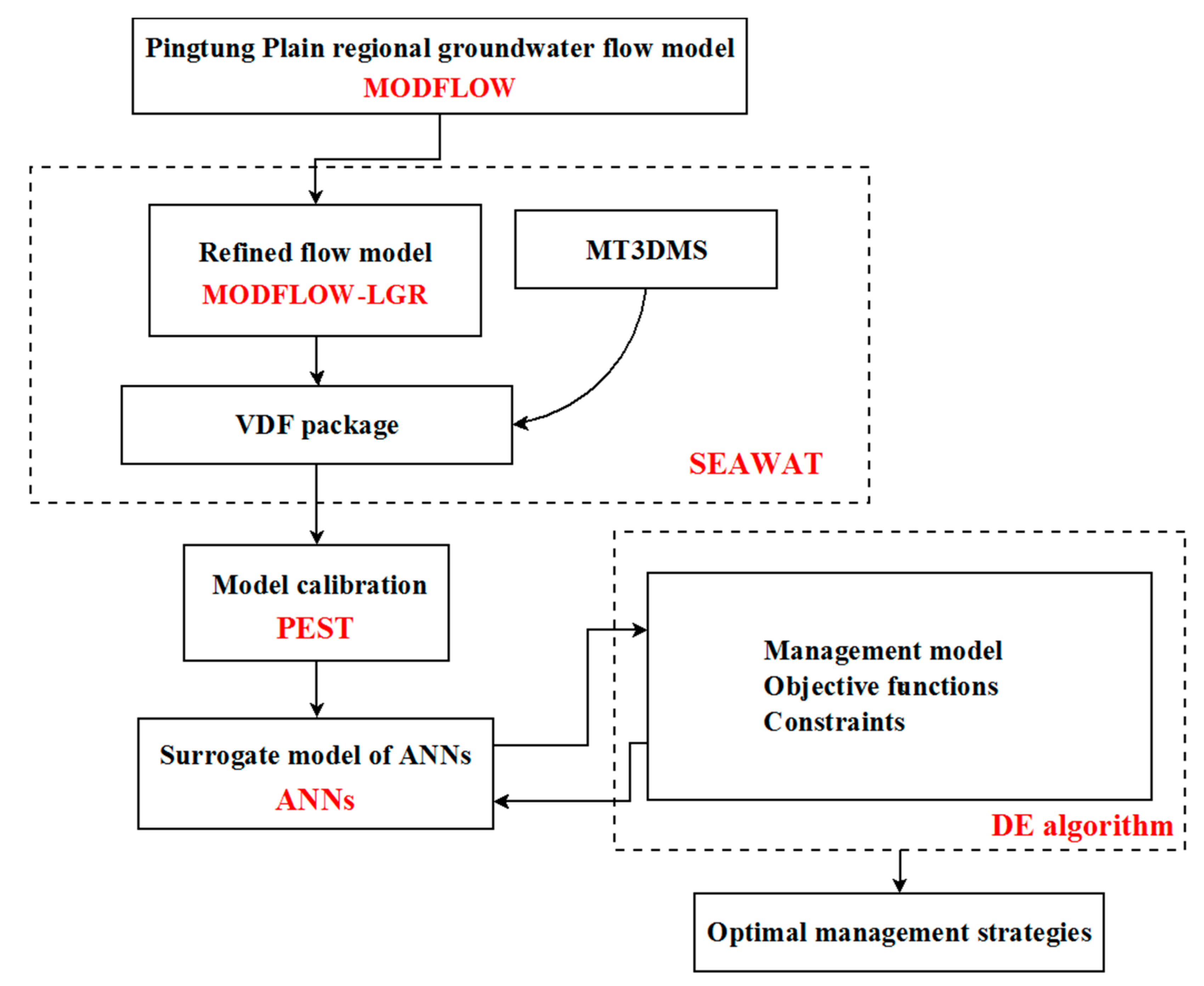
Figure 1. Flowchart of solving simulation–optimization model.
Water 10 00251 g001
Figure 2. (a) The study area of Pingtung Plain in Taiwan; and (b) the cross-section (A–A′) representation of the hydrogeological framework.
Water 10 00251 g002aWater 10 00251 g002b
Figure 3. The concentrations of TDS in Pingtung Plain: (a) aquifer F1; (b) aquifer F2; and (c) aquifer F3-1.
Water 10 00251 g003
Figure 4. Regional groundwater flow model of Pingtung plain: (a) measured head in January, 1999; (b) grid cells and zones of parameters (hydraulic conductivity, specific storage, and specific yield); and (c) simulated groundwater levels in December 2010.
Water 10 00251 g004
Figure 5. The scatter plot of sim and meas. of water levels by regional flow model (Chang [2]).
Water 10 00251 g005
Figure 6. The refined groundwater flow model of Pingtung Plain coastal area: (a) the model grids; (b) simulated groundwater levels at Xinpi; and (c) simulated groundwater levels at Qifeng.
Water 10 00251 g006
Figure 7. The calibrated results of Pingtung Plain SWI model.
Water 10 00251 g007
Figure 8. The deployment of injection barriers for two management scenarios: (a) Scenario #1; (b) aquifer F1 in Scenario #2; (c) aquifer F2 in Scenario #2; (d) aquifer F3-1 in Scenario #2.
Water 10 00251 g008
Figure 9. The optimized results in management Scenario #1: (a) the simulated TDS concentrations after 20-year of remediation using identified optimal injection strategy #1; and (b) the difference of concentrations between 20-year of remediation and the initial condition.
Water 10 00251 g009aWater 10 00251 g009b
Figure 10. The averaged results from six times of repeated optimization processes for each different population size in management Scenario #1.
Water 10 00251 g010
Figure 11. The optimized results in management Scenario #2: (a) the simulated TDS concentrations after 20-year of remediation using identified optimal injection strategy #2; and (b) the difference of concentrations between 20-year of remediation and the initial condition.
Water 10 00251 g011
Figure 12. The averaged results from six times of repeated optimization processes for each different population size in the management Scenario #2.
Water 10 00251 g012
Table 1. The parameter values of Pingtung Plain groundwater flow model and SWI model.
Model ParameterRegional Flow Model (Calibrated by Chang [2])SWI Model(Calibrate Based on Historical TDS Data)
Aquifer F1Aquifer F2Aquifer F3-1Aquifer F1Aquifer F2Aquifer F3-1
Grid cell size in x and y-directions (m)1000 × 1000333 × 333
Grid cell size in z-direction (m)9–854–935–1004.3–17.671.6–2010.3–27.7
Horizontal hydraulic conductivity (m·day−1)0.15–231.550.03–200.300.61–230.000.15–100.0017.12–200.301.98–230.00
Vertical hydraulic conductivity (m·day−1)0.003–4.630.0006–4.000.01–4.600.003–2.000.34–4.000.04–4.60
Specific storage (m−1)6 × 10⁻⁶–6 × 10−56.8 × 10−6–5 × 10−56 × 10−6–4 × 10−56 × 10−6–4 × 10−51 × 10−5–2 × 10−56.75 × 10−6–1.8 × 10⁻⁵
Specific yield (-)0.06–0.30------0.06–0.21------
Dispersivity (m)---------0.01–400.000.01–300.000.001–500.00
Table 2. The testing results of the number of neurons for the hidden layer in ANNs for the management Scenario #1.
Number of NeuronsMean Square Error (MSE)
34.6813
50.72893
70.2347
90.14783
Table 3. The performance of ANNs model for the management Scenarios #1 and #2.
Data SetCorrelation Coefficient (R)
Scenario #1Scenario #2
Training0.997850.96787
Validation0.997870.96741
Testing0.997790.96516
All0.997840.9674
Table 4. The setting of parameter values in the DE algorithm.
Mechanism of Vector SelectionRandom (Uniform Distribution)
Number of decision variables4 in Scenario #1 and 5 in Scenario #2
Lower bound of decision variables0
Upper bound of decision variables1000
Population size30, 50, 100
Max iterations200
Scale factor F0.85
Crossover probability1
Table 5. The optimal results of management Scenarios #1 and #2.
CasesObjective FunctionInjection Rate #1Injection Rate #2Injection Rate #3Injection Rate #4Injection Rate #5
Scenario #1
Case 1-14840.15944.851193.85893.451808.00---
Case 1-26415.301429.751619.851178.002187.70---
Case 1-39825.002633.502436.651991.652763.20---
Scenario #2
Case 2-15446.642505.500.640.0281833.601106.88
Case 2-212964.552694.701069.841040.415010.803148.80
Case 2-326076.506766.507253.521277.225341.105438.16