Article

On the Role of Minor Branches, Energy Dissipation, and Small Defects in the Transient Response of Transmission Mains

by
Silvia Meniconi
1,*,†,
Bruno Brunone
1,† and
Matteo Frisinghelli
2,†
1
Department of Civil and Environmental Engineering, University of Perugia, 06125 Perugia, Italy
2
Novareti SpA, 38068 Rovereto, Italy
*
Author to whom correspondence should be addressed.
These authors contributed equally to this work.
Water 2018, 10(2), 187; https://doi.org/10.3390/w10020187
Submission received: 30 December 2017 / Revised: 6 February 2018 / Accepted: 8 February 2018 / Published: 11 February 2018

Abstract

:
In the last decades several reliable technologies have been proposed for fault detection in water distribution networks (DNs), whereas there are some limitations for transmission mains (TMs). For TM inspection, the most common fault detection technologies are of inline types—with sensors inserted into the pipelines—and then more expensive with respect to those used in DNs. An alternative to in-line sensors is given by transient test-based techniques (TTBTs), where pressure waves are injected in pipes “to explore” them. On the basis of the results of some tests, this paper analyses the relevance of the system configuration, energy dissipation phenomena, and pipe material characteristics in the transient behavior of a real TM. With this aim, a numerical model has been progressively refined not only in terms of the governing equations but also by including a more and more realistic representation of the system layout and taking into account the actual functioning conditions. As a result, the unexpected role of the minor branches—i.e., pipes with a length smaller than the 1% of the length of the main pipe—is pointed out and a preliminary criterion for the system skeletonization is offered. Moreover, the importance of both unsteady friction and viscoelasticity is evaluated as well as the remarkable effects of small defects is highlighted.

1. Introduction

Because of the many differences, it is common ground that fault detection in transmission mains (TMs) is a completely different matter with respect to distribution networks (DNs). On one side, as an example, the accessibility is in favor of DNs. In fact, TMs have less appurtenances and are buried more deeply and in less accessible locations with respect to DNs. This implies the need of using in TMs inspection technologies of an inline type, more expensive than the traditional fixed probes and devices installed in DNs [1]. On the other side, the topology is in favor of TMs. In fact, if transient test-based techniques (TTBTs) were used in DNs, the numerous branches and users would absorb the pressure waves injected in the system before they can interact with the anomalies. This said, two points are very well established: (i) fault detection is a straightforward matter nor for TMs nor for DNs, and (ii) TMs and DNs require different techniques to achieve positive results. Two examples—but several ones could be given—to confirm the validity of these arguments. The first concerns TTBTs: adequate results have been obtained in the leak survey of the Milan (Italy) DN by transient tests only when some parts of the system were deliberately disconnected and then the topology of the system was simplified significantly [2] (it is remarkable to note that the pioneering paper by Liggett and Chen [3], where the Inverse Transient Analysis (ITA) was proposed, concerns looped pipe systems). The second relates the vibroacustic measurements which are very reliable when short pipes (i.e., with a length of few dozens of meters as those connecting the users with the main pipe in DNs) are checked [4,5] but which cannot be used for long pipes because of the large signal attenuation.
A review of the existing methods for fault detection in pipe systems is beyond the aims of this paper where the attention is focused on TMs and, specifically, on the use of TTBTs in these systems. In this context, a possible procedure to follow is outlined in Figure 1 where the most important phases are pointed out. The procedure may be initiated by a failure alarm (phase #0) which in many cases derives simply from leakage clearly visible on a road or an abrupt pressure decrease, pointed out by the monitoring system. The successive phase #1 (“System survey”) requires collecting information about the topology, pipe characteristics, boundary conditions, and appurtenances, if they are not already available. As it will be discussed later on, it should be emphasized that the more accurate the data from the pipe survey the faster the field test campaign and the more reliable the TTBT results.
Based on the findings of the pipe survey, phase #2 (“Numerical model implementation”) can start. Intentionally the word “models” has been chosen to stress that within the procedure several types of models can be used not only with regard to the followed approach—e.g., in the time or frequency domain—but also with respect to their complexity (e.g., Lagrangian models vs. Method of Characteristics models). It is worthy of noting that within the procedure the role of the numerical models is not limited to the analysis of the experimental data (phase #5) but it is also of a crucial importance to design properly and safely the field transients (phase #3). In fact, the preliminary numerical simulations may give an idea of the pressure extreme values achieved during the tests—which is very important for the managers of the pipe system—as well as they are a valuable tool to indicate the measurement sections, to be checked during the successive phase.
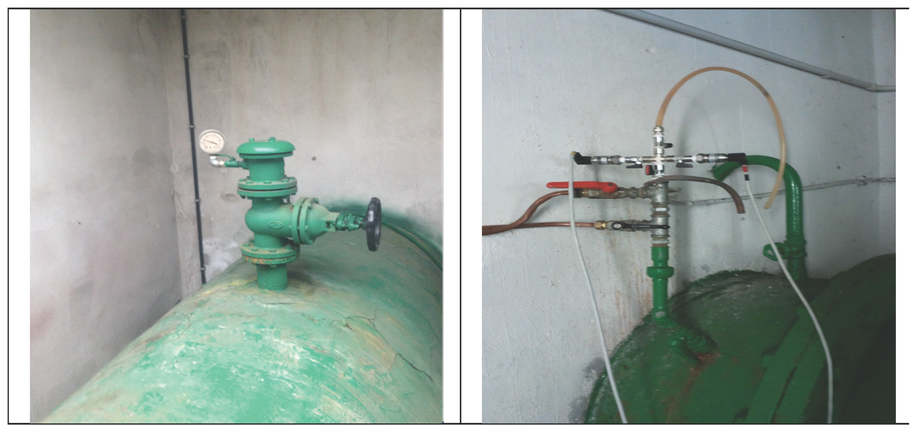
Within phase #3 (“Design of transient tests”), the most appropriate technique for generating effective pressure waves is identified. It is important to note that this is a very important point within TTBTs, since in most cases transients generated by closing the installed valves or by pump shutdown are too slow to point out clearly the existing anomalies. In fact, particularly in TMs, valves are often too large to be operated by hand quickly and when they are motorized the prescribed closure speed is set as small as it does not generate unsafe overpressures. In the case of the pump shutdown, the time the pump takes to stop depends on its inertia which, of course, cannot be changed. As a consequence, there is a need for reliable techniques to generate proper pressure waves (i.e., sharp and compatible with the mechanical characteristics of the pipes). With this aim, the closure of a side discharge valve [6,7], the use of the Portable Pressure Wave Maker (PPWM) device [8,9,10], and the underwater explosion of a cavitating bubble [11,12] have been proposed in literature. Simultaneously, according to the available appurtenances, the measurement sections must be chosen. As mentioned above, TMs are often in less accessible locations but, beyond this, severe limits for the selection of proper measurement sections may also derive from design characteristics. In this respect, Figure 2 reports two examples of TMs (very frequent indeed!) in which the branch, where a probe should be installed, enters an inaccessible tunnel, and then no further measurements can be executed downstream. With regard to the pressure probes, the choice must fall on those with a quite large frequency response (typically of the order of few milliseconds)—to capture rapidly varying pressure signals—and a full scale not much larger than the expected pressure extreme values (from phase #2)—to ensure the best accuracy.
In the successive phase #4 (“Field tests”), preliminary measurements are executed with regard to pre-transient conditions. This may allow understanding the behavior of the system and setting more appropriate initial conditions in transient simulations. Afterwards the transient tests can be executed by using the identified technique. In this respect, according to the functioning conditions and the needs of the water company, it would be important to carry out the same test several times to check its repeatability, as well as the stationarity of the system behavior.
Within phase #5 (“Experimental data analysis”), the acquired pressure signals are examined to extract all the information (i.e., location, type and severity) about possible defects (e.g., leaks [13], partial blockages [14,15], unwanted partially closed in-line valves [16,17], illegal branches [18], and pipe wall deterioration [6]). A review of the existing techniques for the optimal analysis of the experimental data is beyond the aims of this paper which is focused, as shown below, on the crucial role played by the topology and functioning conditions of the system with respect to transient data analysis. Ambiguity and uncertainties occurring within such a phase may suggest refining the system survey (phase #5A) in order to detect possible components (e.g., very short branches, malfunctioning valves) neglected during phase #1. Moreover, further tests can be executed possibly after having simplified the topology of the system (e.g., by closing some branches) in order to improve the effectiveness of the transient tests in terms of the propagation of the pressure waves (i.e., to limit their absorption by secondary parts of the system). Such optional actions improve the performance of the pressure signal analysis and allow detecting and pre-locating the defects (phase #6). It is worthy of pointing out the great importance of the impact of phases #5 and #5A on the numerical models built within phase #2. In fact, the analysis of the experimental data, the execution of further tests, and the availability of a larger number of measurement sections may suggest improvements not only in the model parameters but also in the governing equations.
In the successive phase #7, faults can be located more precisely by means of proper probes (e.g., geo-phones for leak detection, and transients with high frequency waves [19,20]), after having executed a detailed survey of the part of the system highlighted by the previous phase as a possible fault location. Then the remediation actions and the check of the performance of the restored system complete the procedure (phase #8).
This paper presents clear evidence—based on transient tests executed on a real TM—of the unexpected relevance of some components and functioning conditions that, at a first glance, one could be authorized to neglect. Specifically, the crucial role played by some short branches in the transient behavior of the investigated pipe system is pointed out, as well it is confirmed the importance of the malfunctioning [21] of some installed valves that, presumed as totally closed, actually allow leakage, even if quite small. Moreover, the effect on transient pressure signals of the unsteady friction (UF) and difference in pipe materials (elastic and polymeric) is discussed. The method used in this paper for analyzing the experimental data from field tests is based on the use of a numerical model simulating transients in a pipe system. According to the quality of the numerical results, the model complexity is progressively increased by including more realistic representations of the topology as well as more refined governing equations. However, the aim of this paper is not to simulate at the best the experimental results by calibrating the model parameters. On the contrary, its very aim is to point out the improvement in the efficiency of the numerical simulations that can be achieved by including more and more appropriate representation of both the topology and the physical phenomena.

2. The Investigated Transmission Main and Transient Tests

Transient tests have been executed on the Trento steel TM, managed by Novareti SpA, connecting the Spini well-field to the “10,000” reservoir; it supplies the city of Trento, in the northeast of Italy. The original aim of these tests was to increase the number of the available experimental data concerning transients in elastic pipes (e.g., [22,23,24]) with a large value of the initial Reynolds number, R e 0 (= V 0 D / ν , with V 0 = pre-transient mean flow velocity, D = pipe internal diameter, and ν = kinematic viscosity). Such a TM (hereafter referred to as the main pipe), buried at a depth of about 2 m in a porphyry sand, has a total length L = 1322 m, nominal diameter DN500, D = 506.6 mm, and wall thickness equal to 4.19 mm; it was selected since it is classified as a single pipe. In fact, the few minor branches are quite short and were certified by the system manager as inactive (i.e., connecting the main pipe to a dead end or with a closed valve at about the inlet). The diameter of such minor branches, D b , ranges between 80 mm and 506.6 mm, whereas their length, L b , between 0.7 m and 6.8 m and then between the 0.05 % and 0.5 % of L (Figure 3, and Table 1). All branches are in steel with the exception of the E one, which is a high-density polyethylene (HDPE) pipe and consists of two reaches: the first between nodes 12 and 13 (where there is a valve, certified as fully closed) with L b , E = 3.0 m, and the second between nodes 13 and 14 (where there is an inactive well) with L b , E = 15.5 m. During the tests, the initial supplied discharge has been measured at the well-field just upstream of the check valve by means of an electromagnetic flow meter. The pressure signal, H, has been acquired at section M (Figure 3), just downstream of the check valve, by means of a piezoresistive pressure transducer with a full scale ( f s ) of 10 bar, accuracy of 0.25% × f s , and response time of 0.5 ms; the level of the end reservoir has been provided by the data system acquisition of Novareti SpA. Steady-state flow measurements ( R e 0 10 5 ) indicate that a fully rough pipe flow regime happens and provide an estimate of the roughness height equal to 0.8 mm.
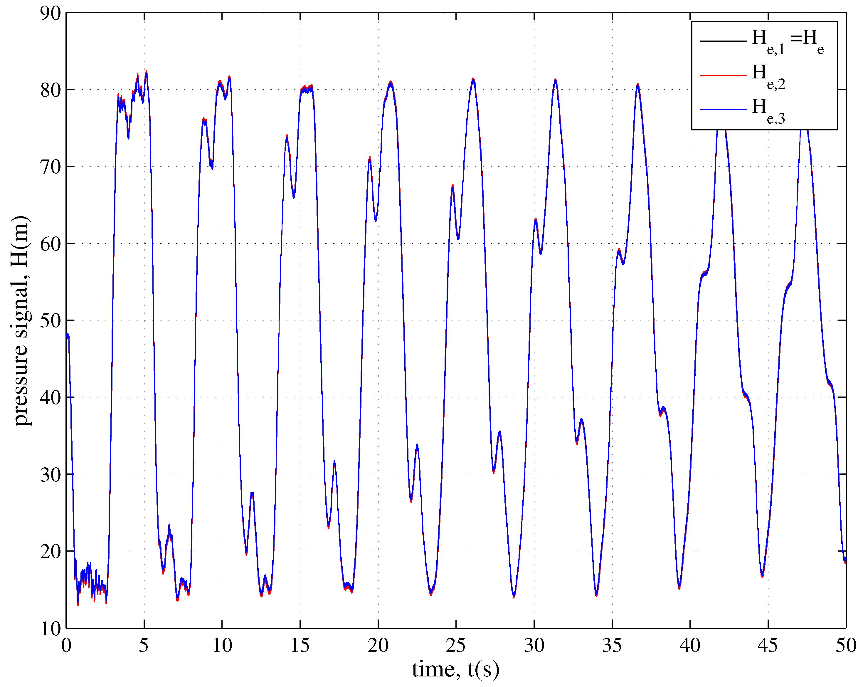
Transients have been generated by pump shutdown at the well-field, by stopping abruptly the electricity supply, and the repeatability of the tests has been checked (Figure 4). On the basis of the experimental pressure signals, the value of the pressure wave speed, a (= 1030 m/s), has been obtained. In the below analysis, the pressure signal H e , 1 (hereafter referred to simply as H e ), with R e 0 = 1.6 × 10 5 , has been considered as representative of all the executed transients (the subscript e indicates the experimental values). It is worthy of noting that, as it will be discussed in the next section, at a first glance the transient response of the examined TM is very different from the one expected if it behaved actually as a single pipe (SP).

3. Numerical Tests for Transient Simulation

Notwithstanding the above mentioned clear perception, in the first step of the pressure signal analysis, the TM has been considered as a single pipe, and the classical water-hammer equations [25] have been used (numerical test for the case of a single pipe, NTSP):
H s + V g V s + 1 g V t + J = 0 ,
being the momentum equation, with s = spatial co-ordinate, t = time (elapsed since the beginning of the transient), g = acceleration due to gravity, and the friction term, J, assumed as equal to the steady-state component, J s , given by the Darcy-Weisbach friction formula:
J = J s = λ V 2 2 g D ,
with λ = friction factor, and
H t + a 2 g V s = 0 ,
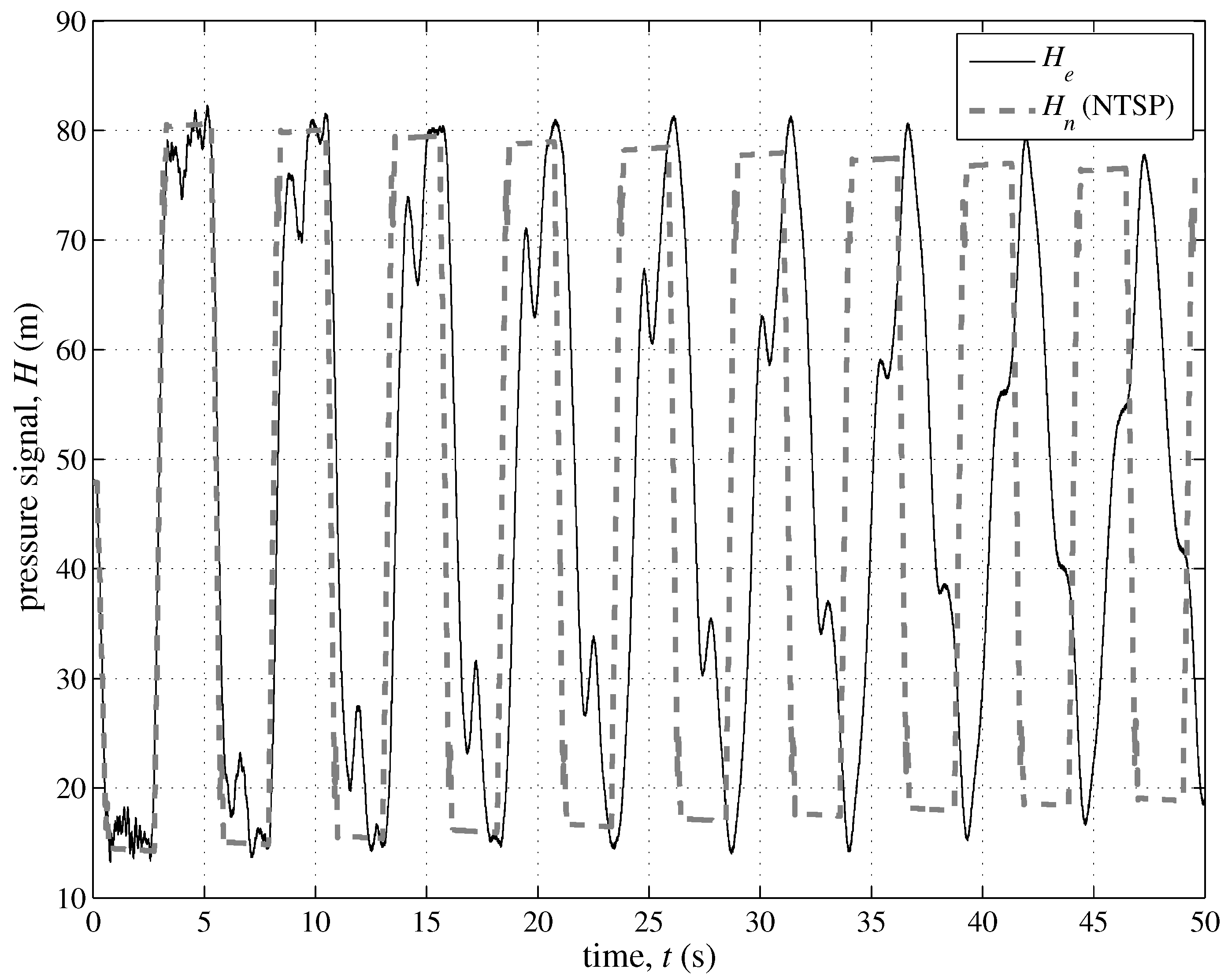
being the continuity equation. As a result, the pressure signal, H n , of Figure 5 is obtained (the subscript n indicates the numerical values), with a value of the Nash-Sutcliffe efficiency coefficient,
E f = 1 i = 1 M ( H e , i H n , i ) 2 ( H e , i H ¯ e ) 2 ,
E f equal to 0.67 , with M = number of samples, and H ¯ e = experimental mean value. Such a poor performance of the classical water hammer equations implies—as it was quite easy to predict—the need of substantial improvements in the model. However, an in-depth analysis of the experimental and numerical pressure signals indicates that a large part of the differences is due to the presence in H e of some further sharp pressure changes—both rises and decreases—other those caused by the pump shutdown and the reflection at the check valve and the downstream reservoir. According to literature [18], the shape of such further pressure changes suggests to explore firstly the role played by the system configuration and specifically that of the minor branches neglected in the SP scheme. Thereafter, the relevance of the unsteady energy dissipation mechanisms (i.e., unsteady friction, UF), the viscoelastic effects (VE) in branch E, and possible small defects will be checked. In Table 2 the main characteristics of the simulated systems and model assumptions and performance are reported.

3.1. The Role of the Minor Branches

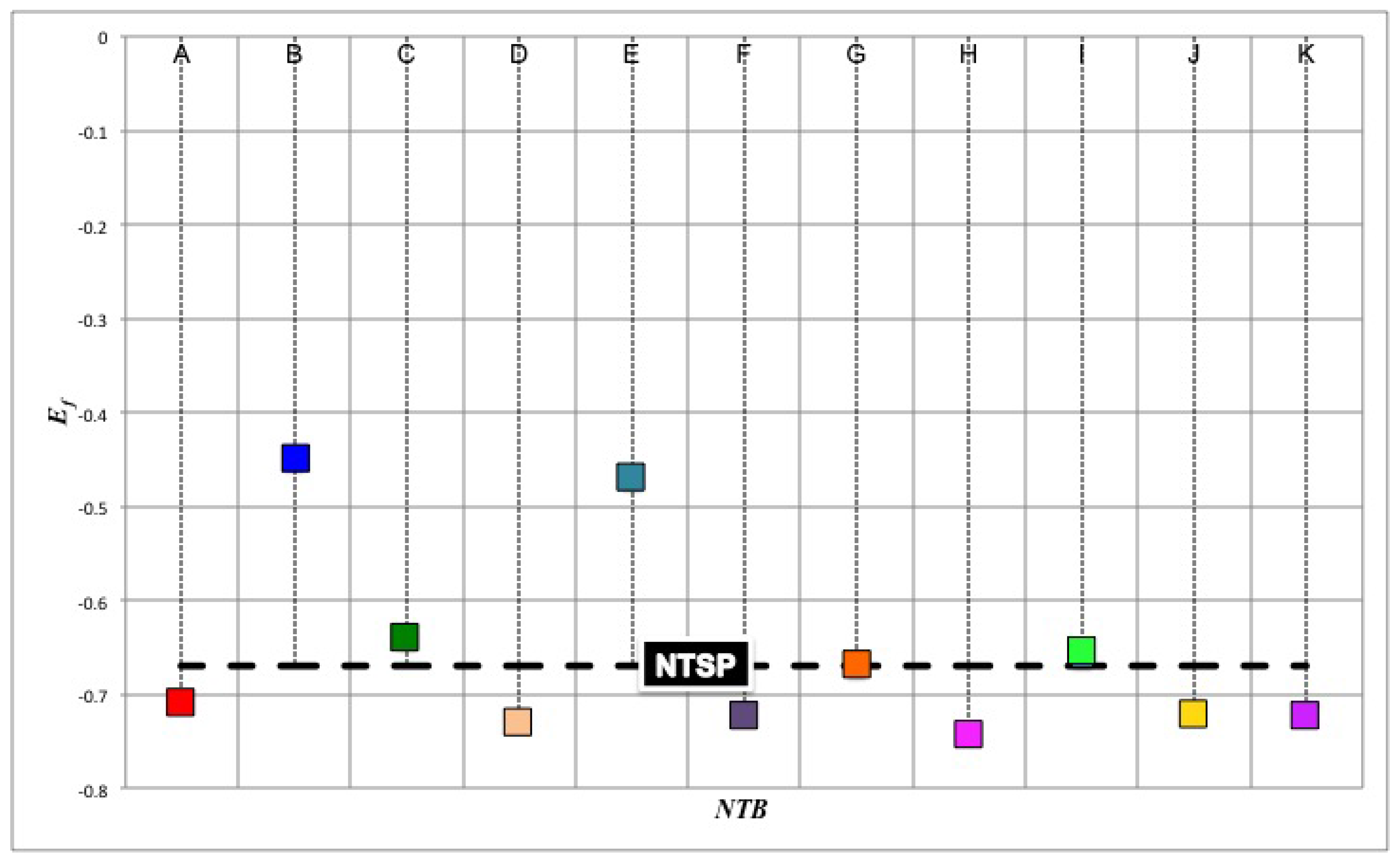
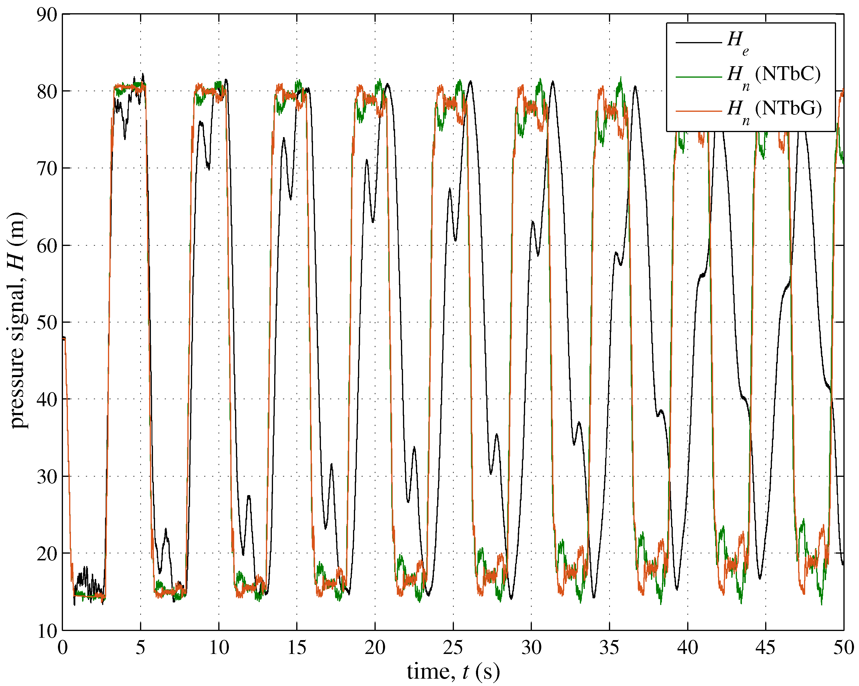
The large complexity of many pipe systems—particularly DNs—has always encouraged the attempt to simplify them but preserving the behavior in steady-state conditions of the real system with respect to a given feature of interest. Emblematic is the case of a branch with numerous users which can be transformed in a pipe with a fictitious constant discharge with the two pipes—the real and the simplified one—having in common only the total head loss (which is the retained feature indeed). In literature, the procedure to simplify a pipe system by excluding the less important branches is defined as skeletonization [26]. In transient conditions, of course, the point is completely different and there is not a clear rule to decide which components of a pipe system must be regarded as crucial. As a consequence, to analyze the relevance of the minor branches of the considered TM, numerical tests have been executed by considering the branches one at a time. Then the obtained values of E f (Table 1) have been compared in Figure 6 with the one (= 0.67 ) pertaining the single pipe (SP). This plot and data reported in Table 1 show that in principle the relevance of a given branch decreases with the distance from the section where the pressure wave is injected into the system. This not only in terms of the mere distance from the injection section, but also with respect to the number and characteristics (e.g, diameter and pressure wave speed) of the branches with which the pressure wave interacts along its path. This result is confirmed by the transient response (Figure 7) of the systems with only branch C (NTbC) or branch G (NTbG), which have almost the same characteristics, but with branch G being at a larger distance from the injection section; Figure 7 shows that the performance of NTbC is quite better than NTbG ( E f = 0.64 and 0.67 , respectively).
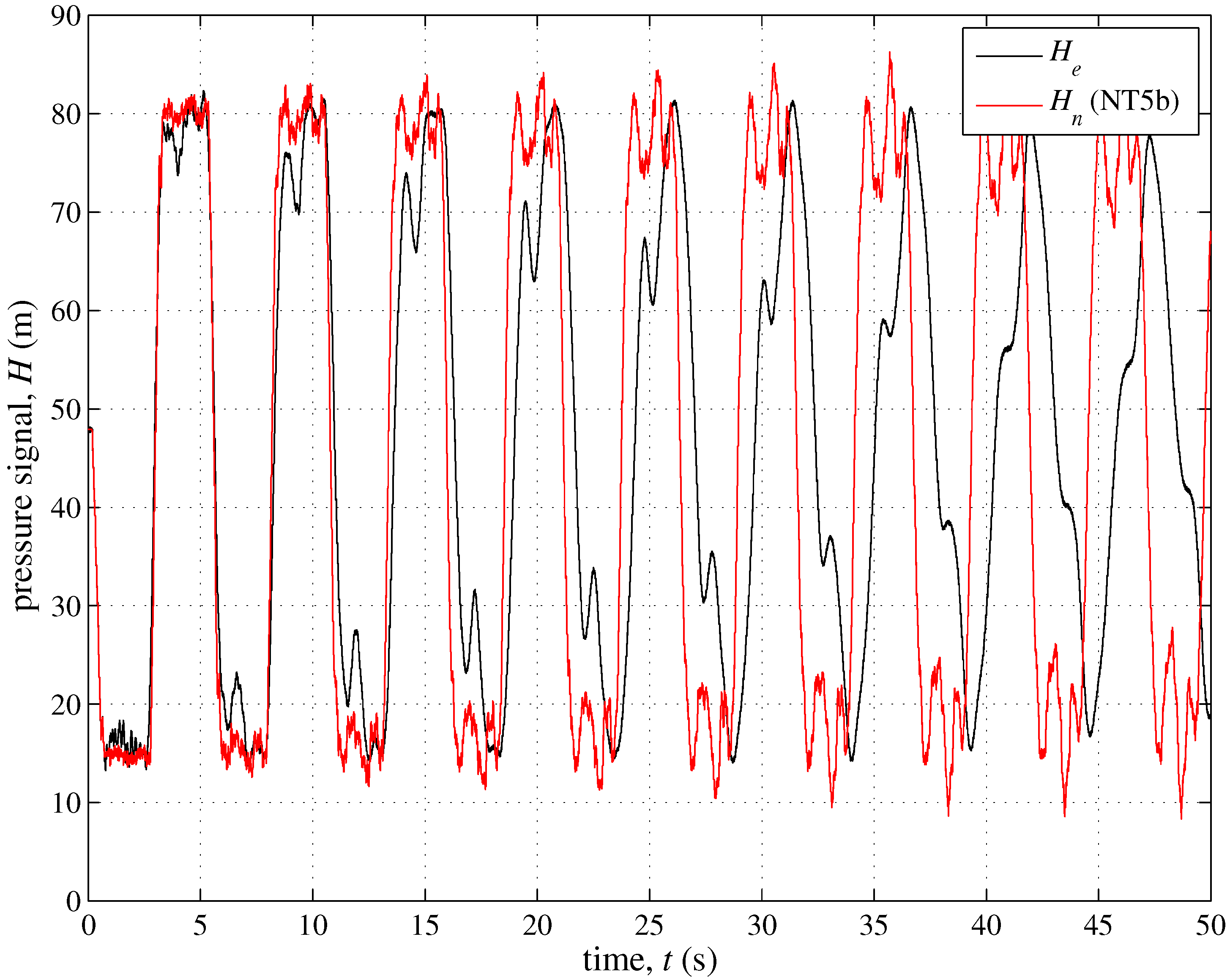
A scrupulous analysis of the effect of a given series of branches on the transient behavior of a TM is beyond the scope of this paper. However, as a preliminary criterion to simplify the system, the branches with a value of E f smaller than the one of SP (i.e., branches A, D, F, H, J, and K) are excluded. As a consequence, in the successive phases of the analysis of the experimental pressure signal only branches B, C, E, G, and I will be retained (NT5b). In Figure 8 the numerical test with such a simplified system is reported: a clear improvement of the performance of the model can be observed ( E f = 0.07 ) with respect to the SP approach ( E f = 0.67 ). Such a significant increase of E f (about the 857% with respect to NTSP) clearly highlights the crucial importance of the branches even if their length is very small with respect to the one of the main pipe.

3.2. The Role of the Unsteady Friction and Viscoelasticity

To take into account the effect of the unsteadiness on the energy dissipation, in Equation (1) the additional unsteady friction (UF) term, J u , evaluated by means of an Instantaneous Acceleration Based (IAB) model [27,28,29,30]:
J u = k U F g V t + sign V V s a V s ,
has been included ( J = J s + J u ), with k U F = unsteady friction coefficient, and sign ( V V / s ) = ( + 1 for V V / s 0 or 1 for V V / s < 0 ). In the used UF model, the coefficient k U F is the only parameter to evaluate. In line with the aims of this paper, the same value of k U F (i.e., the one pertaining to the main pipe) has been considered for all pipes. According to literature—which points out the importance of the initial conditions and relative roughness [31]—the value k U F = 8 × 10 3 has been chosen.
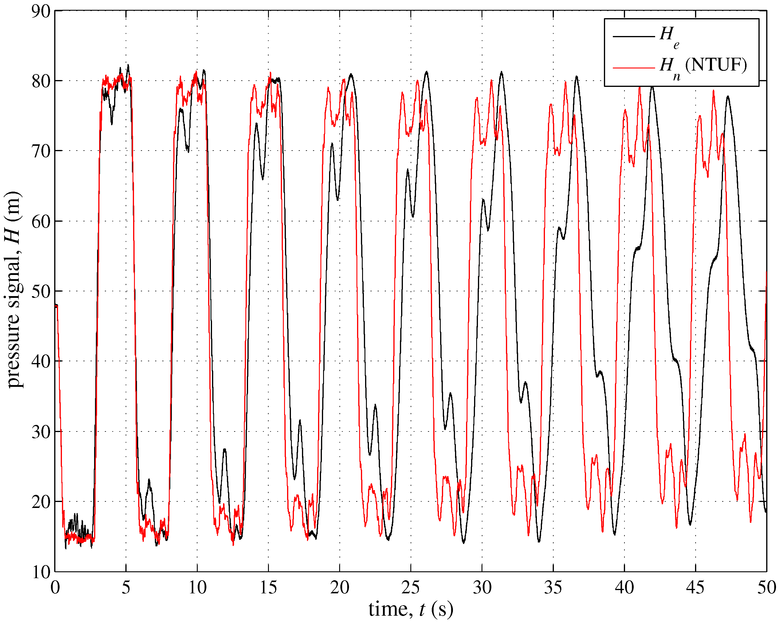
As pressure traces of Figure 9 clearly show, the performance of the model including UF (NTUF) improves significantly with the simulated damping of the pressure peaks quite closer to the experimental one. As a consequence, the efficiency coefficient of NTUF (Table 2) is equal to 0.30, with an increase of about the 528% with respect to NT5b.
To evaluate singly the role played by the mechanical characteristics of pipe material, for the E branch (with L b , E ) the modified continuity equation (see Appendix A):
H t + a 2 g V s + 2 a 2 g d ϵ r d t = 0 ,
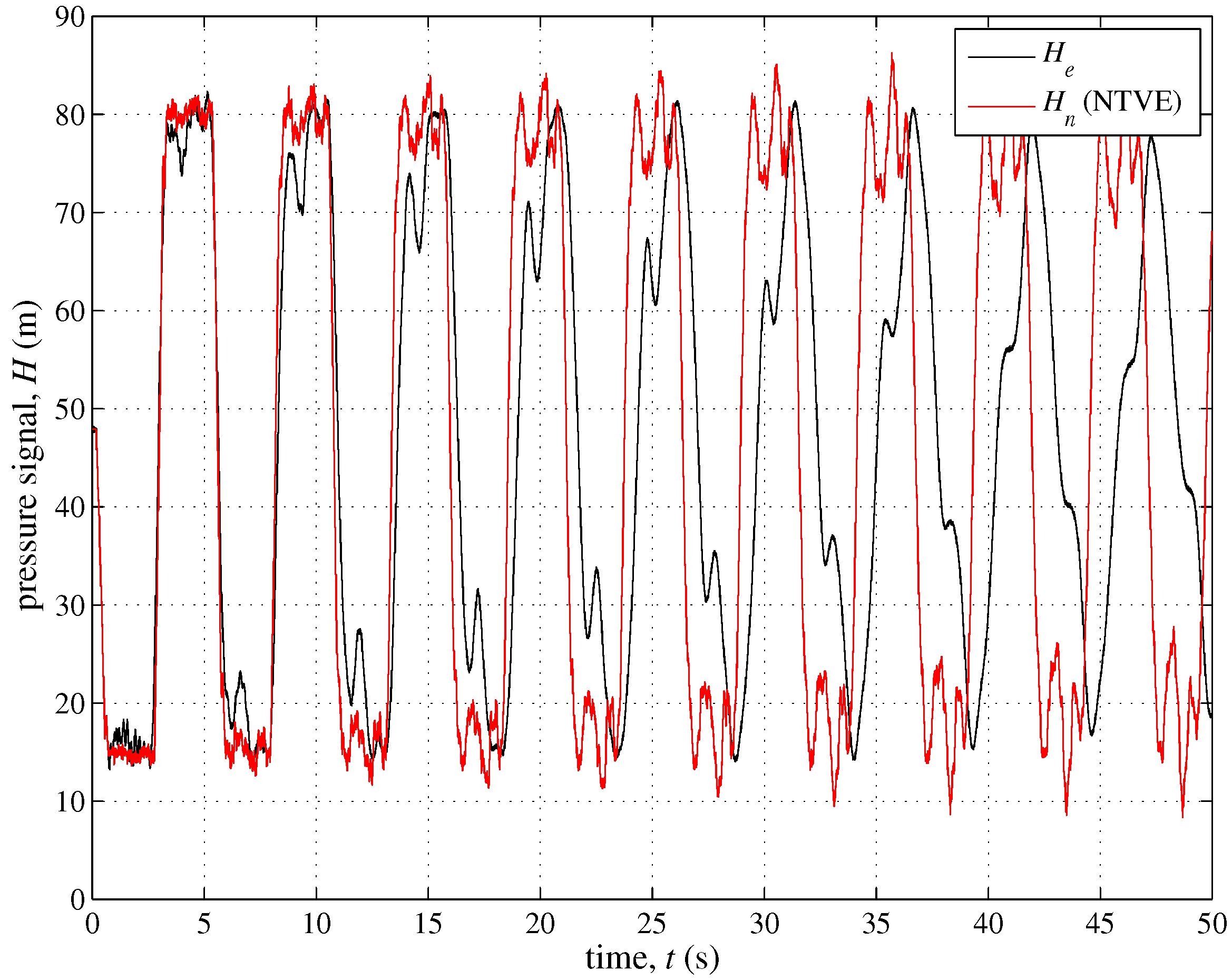
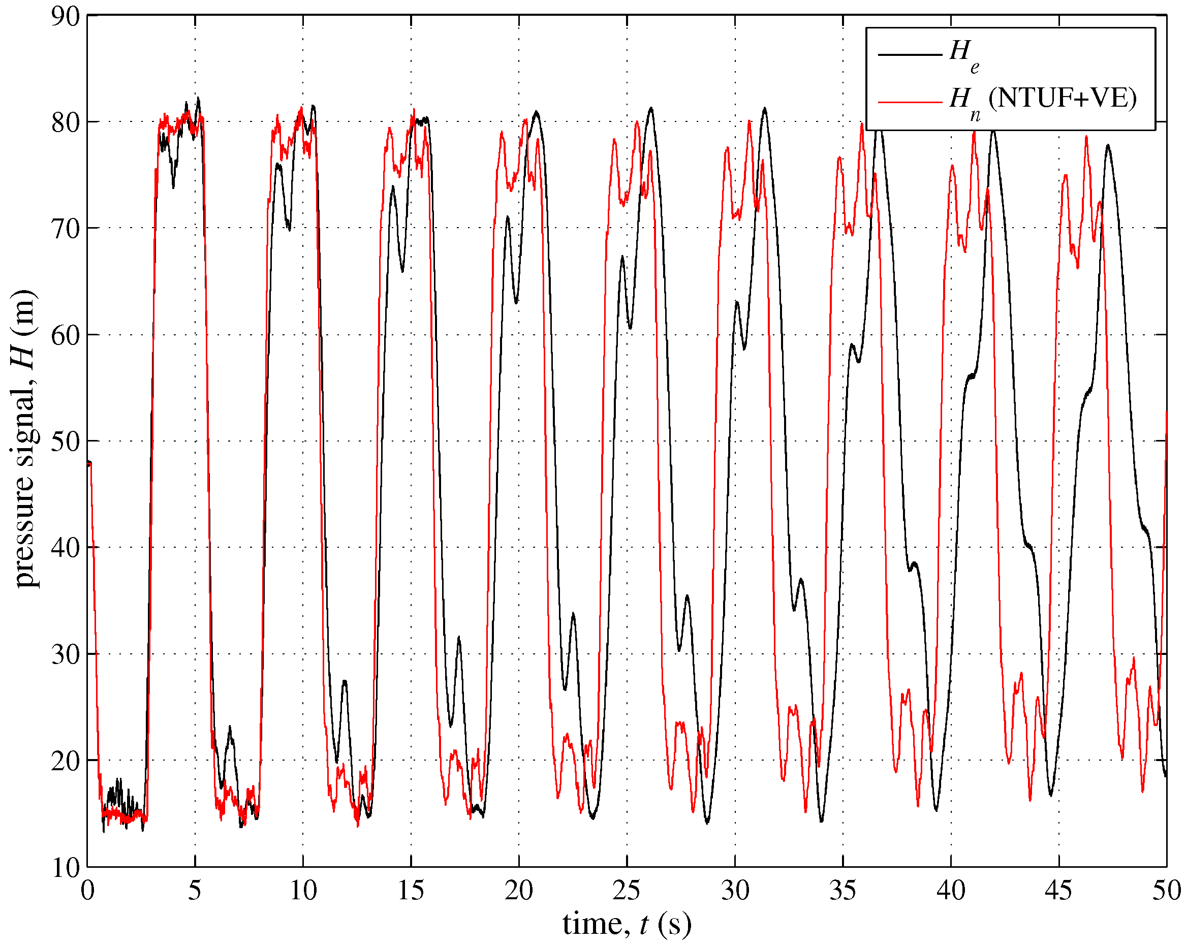
has been considered instead of Equation (3), to simulate the viscoelastic (VE) effects, with ϵ r = retarded strain. In order to evaluate ϵ r , the viscoelastic parameters of the Kelvin-Voigt element, T r (= retardation time) and E r (= dynamic modulus of elasticity) have been chosen according to literature [32]. The resulting pressure signal (Figure 10) indicates clearly that, because of the very small percentage of polymeric pipes (= 0.22%) with respect to the elastic main pipe, the role of viscoelasticity is negligible. As a consequence, the results of NTVE are virtually the same of NT5b ( E f = 0.07 ) as well as the results of NTUF + VE (Figure 11) replicate the ones of NTUF ( E f = 0.30).

3.3. The Role of Small Defects

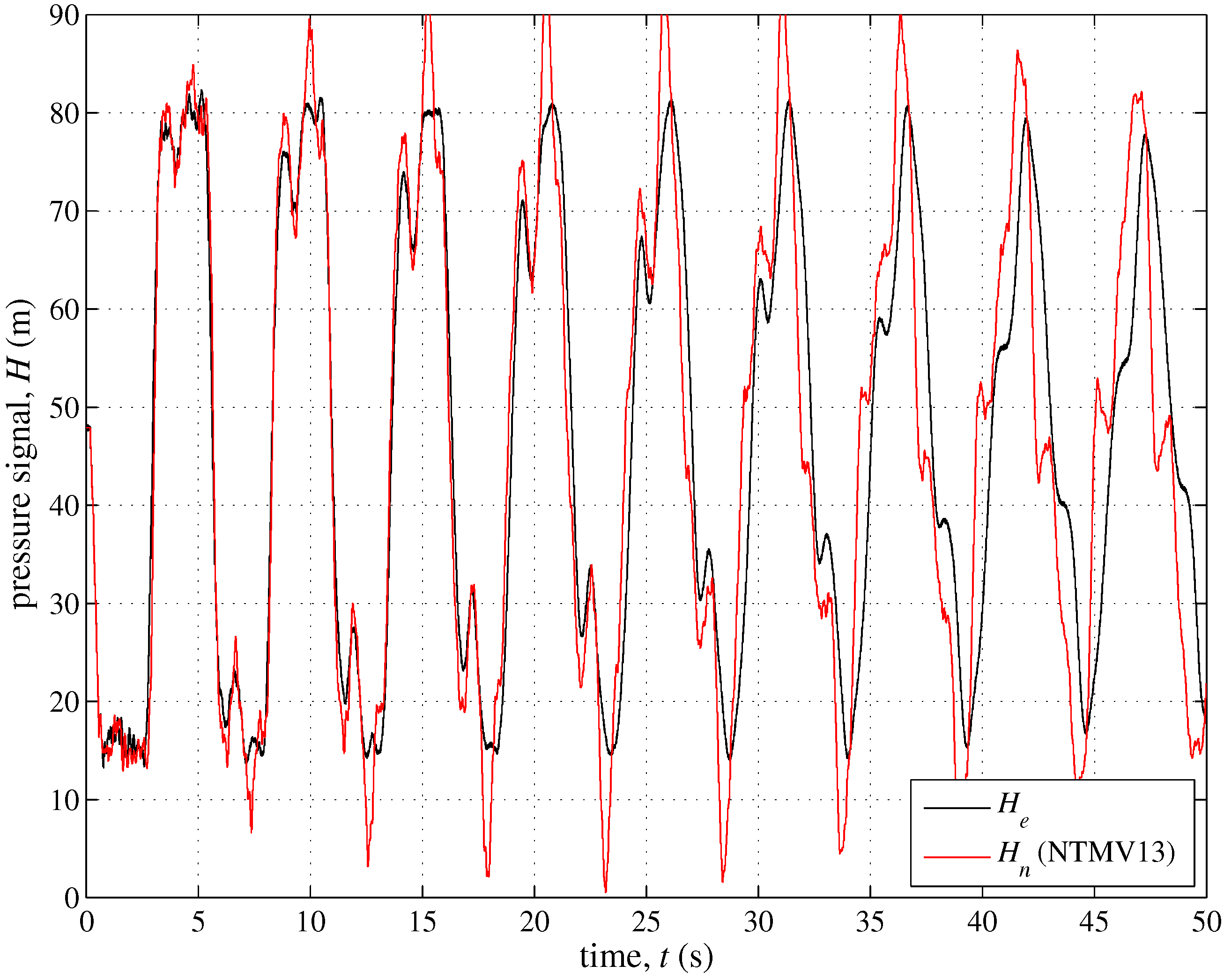
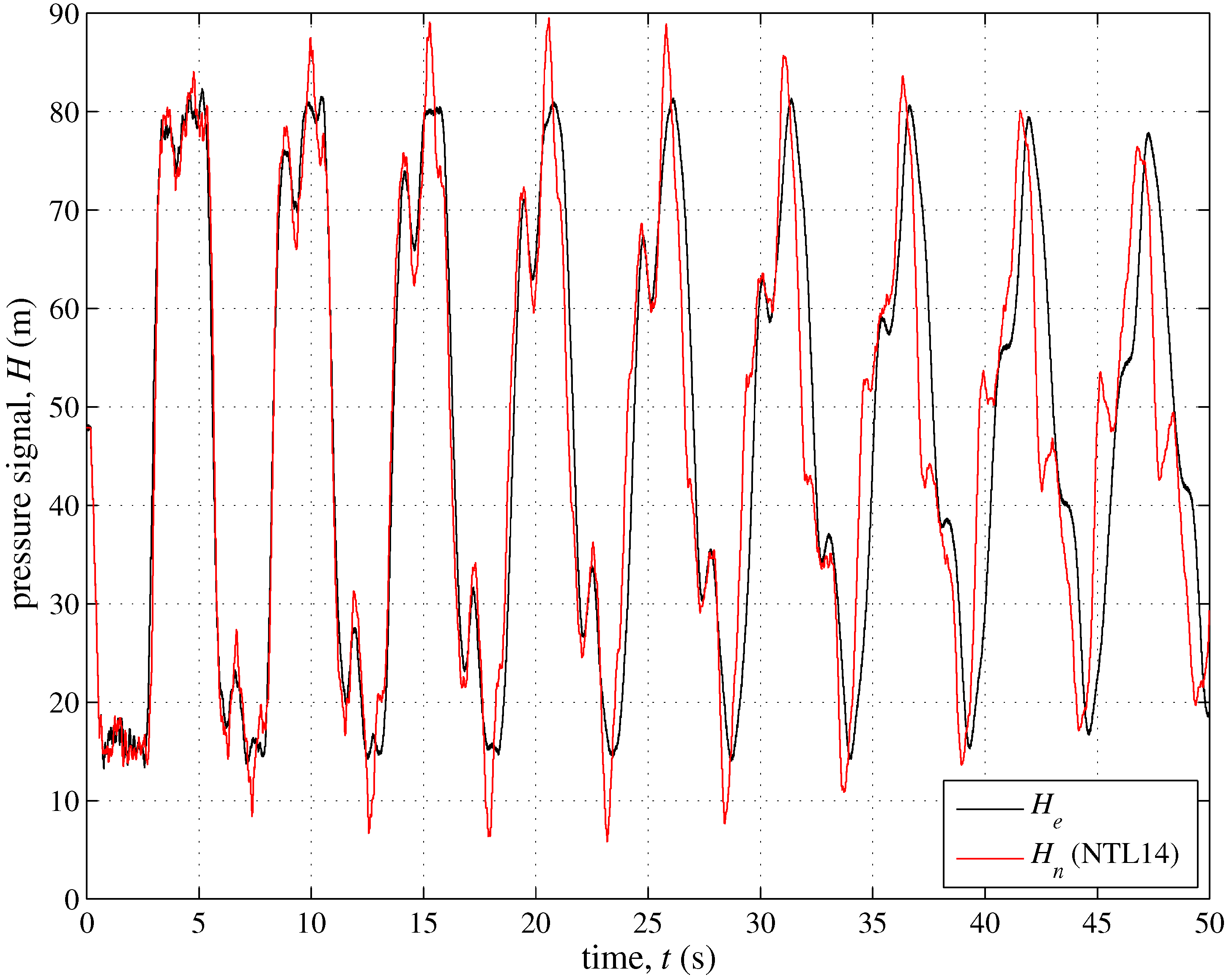
According to literature, from the point of view of transient simulation, the used model contains the most important mechanisms. As a consequence, the not satisfactory values of E f could be ascribed to a not reliable conformity of the assumed layout to the reality. Then, according to phase #5A (Figure 1), an integrative system survey has been executed which revealed the malfunctioning of valves at nodes 13 and 14. This outcome allows hypothesizing different functioning conditions of the E branch: (i) the length is 18.5 m, by assuming L b , E = L b , E + L b , E (NTMV13), because of the malfunctioning of valve 13; (ii) a small discharge, Q L , of about 2 L/s happens towards the unused well located at node 14 (NTL14), because of the malfunctioning of valve at node 14 . Such a value of Q L is compatible with the difference between the discharge supplied at the well-field and the outflow at the end reservoir. Both these scenarios (Figure 12 and Figure 13) exhibit a clear improvement, with E f being equal to 0.80 (NTMV13) and 0.83 (NTL14), and then with an increase of about the 167%, and 177% with respect to NTUF + VE, respectively. In fact, most of the discontinuities of the experimental pressure signal are now captured reasonably well.
Moreover, it is worthy of noting that the reasons of the improvement of E f for NTMV13 are two, both linked to the increase of L b , E , due to the malfunctioning of the valve at node #13. In fact, the larger L b , E , the most significant the role of the branch itself, and the more valuable the effect of the viscoelasticity (e.g., [33,34]).
Notwithstanding the valuable improvement in terms of E f from NTSP to NTL14, a quite remarkable difference between the experimental and numerical pressure signals still remains. Such a partial failure of the numerical model can be ascribed to several reasons. First of all the deliberately omitted parameter calibration must be mentioned. In fact, in the paper the values of the unsteady friction coefficient and viscoelastic parameters of literature have been used, even if reliable criteria for evaluating such quantities is still an open problem. Secondly, a possible inaccuracy in the description of the system topology which, as shown in this paper, has a significant effect on the numerical simulations, even if quite small. Finally, possible undetected localized phenomena (e.g., water column separation) might have caused further pressure waves.

4. Conclusions

Unsteady-state tests executed on the Trento TM by a pump shutdown have disclosed the unexpected remarkable effect of the short minor branches—essentially inactive—on the transient response of the investigated pipe system. In fact, the experimental pressure signal shows clear sharp changes beyond those due to the pressure wave reflection at the upstream and downstream boundaries (i.e., the check valve at the well-field and the downstream end reservoir). By means of the numerical model, the relevance of the topology, pipe material characteristics, transient energy dissipation, and defects has been explored. The performance of the numerical model has been evaluated on the basis of the Nash Sutcliffe efficiency coefficient. A preliminary criterion for the skeletonization of the TM has been proposed.
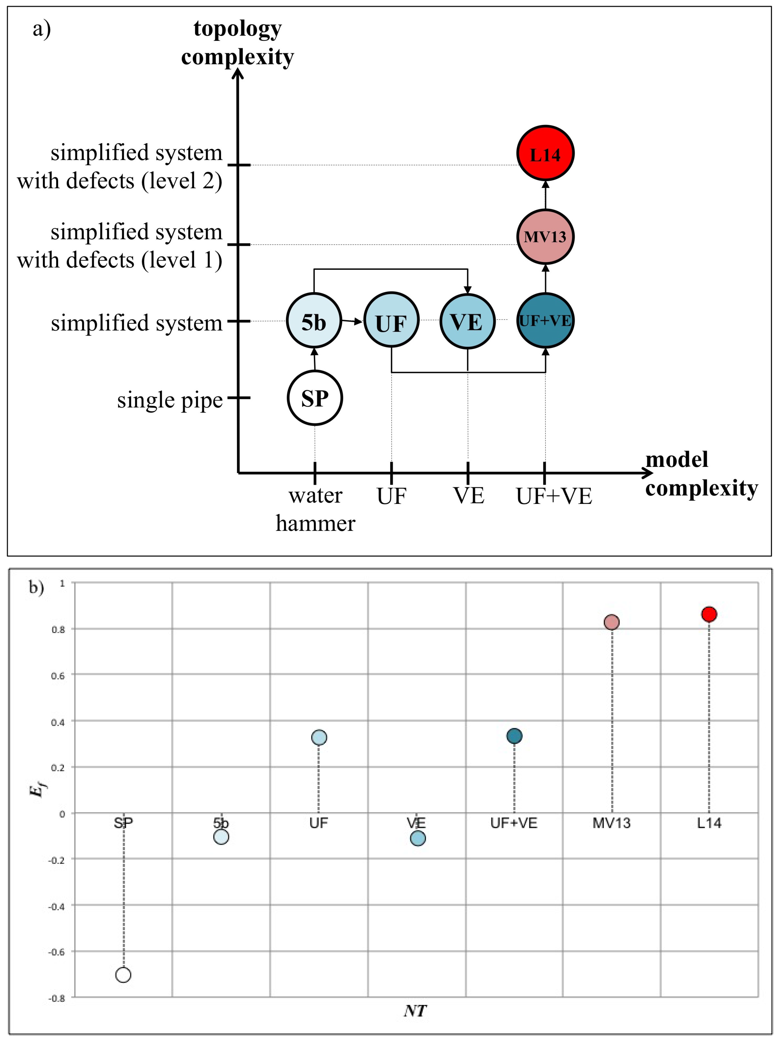
In Figure 14a, the progressively refinement of the model, with the relative values of the efficiency (Figure 14b), is clarified, as a succession of more and more complex numerical model and topology. From Figure 14b, it emerges the very crucial role played by secondary branches, particularly the five most important. Specifically, the largest increase (≃857%) in the numerical performance is achieved when these branches are included in the system topology. As a consequence, a more in depth analysis for the skeletonization of pipe systems with respect to the unsteady-state flow is an urgent need, in order to use TTBT reliably for fault detection in complex pipe systems. A less important but still significant improvement is obtained when the unsteady friction is taken into account (≃528%). On the contrary, the role of the viscoelasticity becomes relevant only when the length of the polymeric branch is appreciable. Finally, an important contribution for the simulation of sharp pressure changes is given by the inclusion of small defects (i.e., malfunctioning valves).

Acknowledgments

This research has been funded by the Hong Kong (HK) Research Grant Council Theme-Based Research Scheme and the HK University of Science and Technology (HKUST) under the project “Smart Urban Water Supply System (Smart UWSS)”, University of Perugia, and Fondazione Cassa Risparmio Perugia (project No. 2017.0234.021). Tests have been executed within a research project in co-operation with Novareti SpA, Trento. The support in the preparation and execution of the field tests of E. Mazzetti, C. Capponi, and C. Del Principe of the University of Perugia, and M. Larentis, and C. Costisella of Novareti SpA is highly appreciated.

Author Contributions

S. Meniconi, B. Brunone and M. Frisinghelli conceived, designed and performed the experiments; S. Meniconi, and B. Brunone analyzed the data; M. Frisinghelli contributed materials tools; S. Meniconi, and B. Brunone wrote the paper.

Conflicts of Interest

The authors declare no conflict of interest.

Appendix A. Single Element Kelvin-Voigt (1 K-V) Models

With respect to elastic materials, when a circumferential stress, σ , is applied to a viscoelastic material, the total strain, ϵ , is given by the sum of the instantaneous elastic, ϵ el , and retarded component, ϵ r [35,36,37,38,39,40,41,42]:
ϵ = ϵ el + ϵ r .
Such a behavior can be simulated by means of a single element Kelvin-Voigt (1 K-V) model where a viscous damper and an elastic spring, connected in parallel, are jointed to a simple elastic spring in series. Within 1 K-V models, the following relationship links σ and ϵ r :
σ = E r ϵ r + E r T r d ϵ r d t ,
where E r = dynamic modulus of elasticity, and T r = retardation time of the KV element. According to the Hooke’s law, the elastic strain, ϵ el , of the spring is given by:
ϵ el = σ E el ,
where the elastic Young’s modulus of elasticity, E el , is linked to a [43] by:
a = k ρ 1 + ψ k D e E el ,
with k = bulk modulus of elasticity, and ψ = dimensionless parameter accounting for longitudinal support situation [44,45].
The above difference between elastic and viscoelastic materials reflects in the continuity equation and then the following term must be added in Equation (3):
2 a 2 g d ϵ r d t .

References

  1. Laven, L.; Lambert, A.O. What do we know about real losses on transmission mains? In Proceedings of the IWA Specialised Conference “Water Loss 2012”, Manila, Philippines, 26–29 February 2012. [Google Scholar]
  2. Meniconi, S.; Brunone, B.; Ferrante, M.; Capponi, C.; Carrettini, C.A.; Chiesa, C.; Segalini, D.; Lanfranchi, E.A. Anomaly pre-localization in distribution-transmission mains by pump trip: Preliminary field tests in the Milan pipe system. J. Hydroinform. 2015, 17, 377–389. [Google Scholar] [CrossRef]
  3. Liggett, J.A.; Chen, L.C. Inverse transient analysis in pipe networks. J. Hydraul. Eng. 1994, 120, 934–955. [Google Scholar] [CrossRef]
  4. Martini, A.; Troncossi, M.; Rivola, A. Vibroacoustic measurements for detecting water leaks in buried small-diameter plastic pipes. J. Pipeline Syst. Eng. Pract. 2017, 8, 04017022. [Google Scholar] [CrossRef]
  5. Martini, A.; Troncossi, M.; Rivola, A. Leak detection in water-filled small-diameter polyethylene pipes by means of acoustic emission measurements. Appl. Sci. 2017, 7. [Google Scholar] [CrossRef]
  6. Stephens, M.; Lambert, M.F.; Simpson, A.R. Determining the internal wall condition of a water pipeline in the field using an inverse transient. J. Hydraul. Eng. 2013, 139, 310–324. [Google Scholar] [CrossRef]
  7. Taghvaei, M.; Beck, S.B.M.; Boxall, J.B. Leak detection in pipes using induced water hammer pulses and cepstrum analysis. Int. J. COMADEM 2010, 13, 19–25. [Google Scholar]
  8. Brunone, B.; Ferrante, M.; Meniconi, S. Portable pressure wave-maker for leak detection and pipe system characterization. J. Am. Water Works Assoc. 2008, 100, 108–116. [Google Scholar]
  9. Meniconi, S.; Brunone, B.; Ferrante, M.; Massari, C. Small amplitude sharp pressure waves to diagnose pipe systems. Water Resour. Manag. 2011, 25, 79–96. [Google Scholar] [CrossRef]
  10. Meniconi, S.; Brunone, B.; Frisinghelli, M.; Mazzetti, E.; Larentis, M.; Costisella, C. Safe transients for pipe survey in a real transmission main by means of a portable device: The case study of the Trento (I) supply system. Procedia Eng. 2017, 186, 228–235. [Google Scholar] [CrossRef]
  11. Mazzocchi, E.; Pachoud, A.J.; Farhat, M.; Hachem, F.E.; Cesare, G.D. Signal analysis of an actively cavitation bubble in pressurized pipes for detection of wall stiffness drops. J. Fluids Struct. 2016, 65, 60–75. [Google Scholar] [CrossRef]
  12. Gong, J.; Lambert, M.F.; Nguyen, S.T.N.; Zecchin, A.C.; Simpson, A.R. Detecting thinner-walled pipe sections using a spark transient pressure wave generator. J. Hydraul. Eng. 2018, 144, 06017027. [Google Scholar] [CrossRef]
  13. Covas, D.; Ramos, H. Case studies of leak detection and location in water pipe systems by inverse transient analysis. J. Wat. Res. Plan. Man. 2010, 136, 248–257. [Google Scholar] [CrossRef]
  14. Duan, H.; Lee, P.; Ghidaoui, M.; Tuck, J. Transient wave-blockage interaction and extended blockage detection in elastic water pipelines. J. Fluids Struct. 2014, 46, 2–16. [Google Scholar] [CrossRef]
  15. Meniconi, S.; Brunone, B.; Ferrante, M.; Capponi, C. Mechanism of interaction of pressure waves at a discrete partial blockage. J. Fluids Struct. 2016, 62, 33–45. [Google Scholar] [CrossRef]
  16. Contractor, D.N. The reflection of waterhammer pressure waves from minor losses. J. Basic Eng. 1965, 87, 445–451. [Google Scholar] [CrossRef]
  17. Meniconi, S.; Brunone, B.; Ferrante, M. In-line pipe device checking by short period analysis of transient tests. J. Hydraul. Eng. 2011, 137, 713–722. [Google Scholar] [CrossRef]
  18. Meniconi, S.; Brunone, B.; Ferrante, M.; Massari, C. Transient tests for locating and sizing illegal branches in pipe systems. J. Hydroinform. 2011, 13, 334–345. [Google Scholar] [CrossRef]
  19. Louati, M.; Ghidaoui, M.S. High frequency acoustic wave properties in a water-filled pipe. Part 1: Dispersion and multi-path behavior. J. Hydraul. Res. 2017, 55, 613–631. [Google Scholar] [CrossRef]
  20. Louati, M.; Ghidaoui, M.S. High frequency acoustic wave properties in a water-filled pipe. Part 2: Range of propagation. J. Hydraul. Res. 2017, 55, 632–646. [Google Scholar] [CrossRef]
  21. Meniconi, S.; Brunone, B.; Ferrante, M.; Massari, C. Potential of transient tests to diagnose real supply pipe systems: What can be done with a single extemporary test. J. Water Resour. Plan. Manag. 2010, 137, 238–241. [Google Scholar] [CrossRef]
  22. Meniconi, S.; Duan, H.; Brunone, B.; Ghidaoui, M.; Lee, P.; Ferrante, M. Further developments in rapidly decelerating turbulent pipe flow modeling. J. Hydraul. Eng. 2014, 140, 04014028. [Google Scholar] [CrossRef]
  23. Adamkowski, A.; Lewandowski, M. Experimental examination of unsteady friction models for transient pipe flow simulation. J. Fluids Eng. Trans. ASME 2006, 128, 1351–1363. [Google Scholar] [CrossRef]
  24. Liou, J.C.P. Understanding line packing in frictional water hammer. J. Fluids Eng. Trans. ASME 2016, 138, 081303. [Google Scholar] [CrossRef]
  25. Wylie, E.; Streeter, V. Fluid Transients in Systems; Prentice-Hall Inc.: Upper Saddle River, NJ, USA, 1993; p. 463. [Google Scholar]
  26. Larock, B.E.; Jeppson, R.W.; Watters, G.Z. Hydraulics of Pipeline Systems; CRC Press: Boca Raton, FL, USA, 1999; p. 552. [Google Scholar]
  27. Bergant, A.; Simpson, A.R.; Vitkovsky, J. Developments in unsteady pipe flow friction modelling. J. Hydraul. Res. 2001, 39, 249–257. [Google Scholar] [CrossRef] [Green Version]
  28. Brunone, B.; Morelli, L. Automatic control valve induced transients in an operative pipe system. J. Hydraul. Eng. 1999, 125, 534–542. [Google Scholar] [CrossRef]
  29. Brunone, B.; Golia, U.M. Discussion of “Systematic evaluation of one-dimensional unsteady friction models in simple pipelines” by J.P. Vitkovsky, A. Bergant, A.R. Simpson, and M. F. Lambert. J. Hydraul. Eng. 2008, 134, 282–284. [Google Scholar] [CrossRef]
  30. Ghidaoui, M.S.; Zhao, M.; McInnis, D.A.; Axworthy, D.H. A review of water hammer theory and practice. Appl. Mech. Rev. 2005, 58, 49–76. [Google Scholar] [CrossRef]
  31. Pezzinga, G. Evaluation of unsteady flow resistances by quasi-2D or 1D models. J. Hydraul. Eng. 2000, 126, 778–785. [Google Scholar] [CrossRef]
  32. Pezzinga, G.; Brunone, B.; Meniconi, S. Relevance of pipe period on Kelvin-Voigt viscoelastic parameters: 1D and 2D inverse transient analysis. J. Hydraul. Eng. 2016, 142, 04016063. [Google Scholar] [CrossRef]
  33. Pezzinga, G.; Scandura, P. Unsteady flow in installations with polymeric additional pipe. J. Hydraul. Eng. 1995, 121, 802–811. [Google Scholar] [CrossRef]
  34. Pezzinga, G. Unsteady flow in hydraulic networks with polymeric additional pipe. J. Hydraul. Eng. 2002, 128, 238–244. [Google Scholar] [CrossRef]
  35. Covas, D.; Stoianov, I.; Mano, J.F.; Ramos, H.; Graham, N.; Maksimovic, C. The dynamic effect of pipe-wall viscoelasticity in hydraulic transients. Part II—Model development, calibration and verification. J. Hydraul. Res. 2005, 43, 56–70. [Google Scholar] [CrossRef]
  36. Franke, P.G.; Seyler, F. Computation of unsteady pipe flow with respect to visco-elastic material properties. J. Hydraul. Res. 1983, 21, 345–353. [Google Scholar] [CrossRef]
  37. Keramat, A.; Tijsseling, A.S.; Hou, Q.; Ahmadi, A. Fluid-structure interaction with pipe-wall viscoelasticity during water hammer. J. Fluids Struct. 2012, 28, 434–455. [Google Scholar] [CrossRef]
  38. Keramat, A.; Kolahi, A.G.; Ahmadi, A. Water hammer modeling of viscoelastic pipes with a time-dependent Poisson’s ratio. J. Fluids Struct. 2013, 43, 164–178. [Google Scholar] [CrossRef]
  39. Soares, A.K.; Covas, D.; Reis, L.F. Analysis of PVC pipe-wall viscoelasticity during water hammer. J. Hydraul. Eng. 2008, 134, 1389–1395. [Google Scholar] [CrossRef]
  40. Weinerowska-Bords, K. Accuracy and parameter estimation of elastic and viscoelastic models of the water hammer. Task Q. 2007, 11, 383–395. [Google Scholar]
  41. Meniconi, S.; Brunone, B.; Ferrante, M.; Massari, C. Energy dissipation and pressure decay during transients in viscoelastic pipes with an in-line valve. J. Fluid Struct. 2014, 45, 235–249. [Google Scholar] [CrossRef]
  42. Pezzinga, G.; Brunone, B.; Cannizzaro, D.; Ferrante, M.; Meniconi, S.; Berni, A. Two-dimensional features of viscoelastic models of pipe transients. J. Hydraul. Eng. 2014, 140, 04014036. [Google Scholar] [CrossRef]
  43. Hachem, F.E.; Schleiss, A.J. A review of wave celerity in frictionless and axisymmetrical steel-lined pressure tunnels. J. Fluids Struct. 2011, 27, 311–328. [Google Scholar] [CrossRef]
  44. Parmakian, J. Waterhammer Analysis; Dover: New York, NY, USA, 1963. [Google Scholar]
  45. Montuori, C. Colpo d’ariete in presenza di resistenze in condotte di notevole spessore. L’Energia Elettrica 1966, XLIII, 1–18. (In Italian) [Google Scholar]
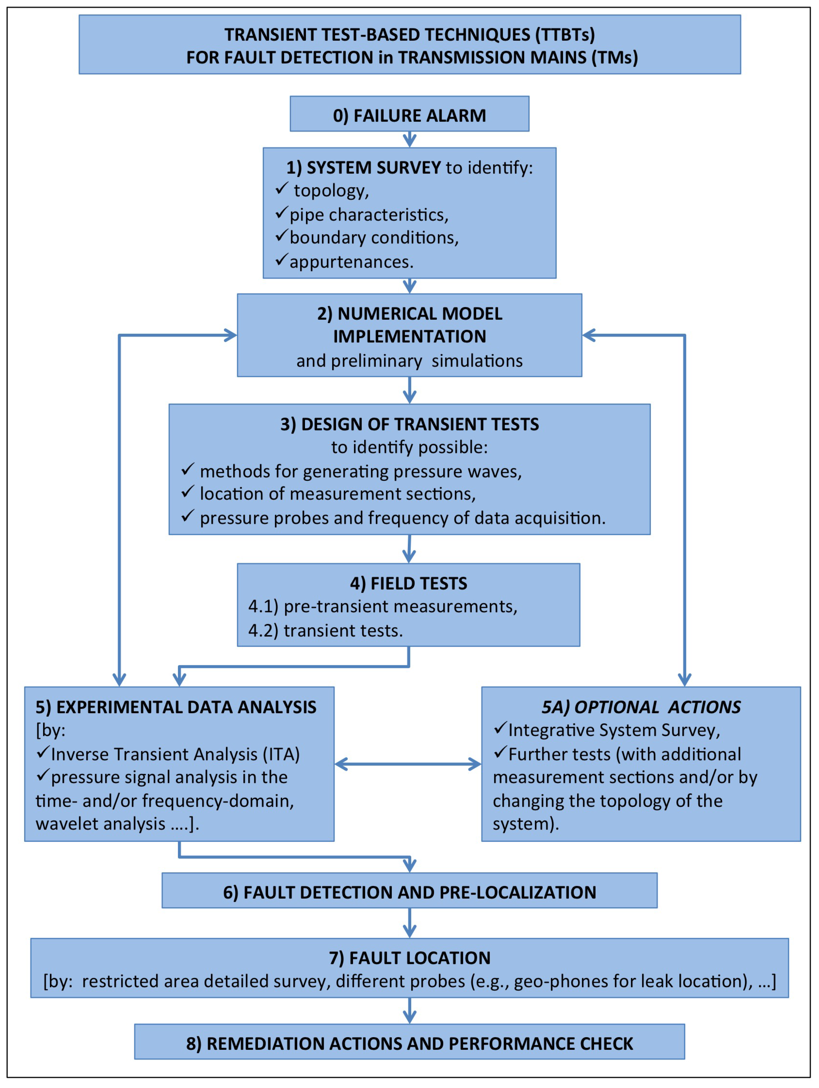
Figure 1. Transient test-based techniques (TTBTs) for fault detection in Transmission Mains (TMs): main phases of the procedure with highlighted the interactions between them.
Water 10 00187 g001
Figure 2. Typical TM branches where the inaccessibility is evident: the only appurtenance is just upstream of an inaccessible tunnel.
Water 10 00187 g002
Figure 3. Trento TM layout (note that letters indicate the branches, whereas numbers indicate the nodes of the system; in particular: 1-well-field; M-measurement section; 27-downstream end reservoir; a different length scale has been used for the main pipe and minor branches).
Water 10 00187 g003
Figure 4. Trento TM: transient tests generated by pump shutdown. Note that the behavior of the pressure signals testifies the repeatability of tests.
Water 10 00187 g004
Figure 5. Trento TM: transient generated by pump shutdown at the well-field. Experimental pressure signal, H e , at section M vs. model simulation, H n , for the single pipe scheme (NTSP).
Water 10 00187 g005
Figure 6. Trento TM: transient tests generated by pump shutdown. Performance of the numerical model by considering the branches one at a time.
Water 10 00187 g006
Figure 7. Trento TM: transient generated by pump shutdown at the well-field. Experimental pressure signal, H e , at section M vs. model simulation, H n , for the system with only branch C (NTbC), and only branch G (NTbG).
Water 10 00187 g007
Figure 8. Trento TM: transient generated by pump shutdown at the well-field. Experimental pressure signal, H e , at section M vs. model simulation, H n , for the system with 5 branches (B, C, E, G and I) selected by means of the value of E f (NT5b).
Water 10 00187 g008
Figure 9. Trento TM: transient generated by pump shutdown at the well-field. Experimental pressure signal, H e , at section M vs. model simulation, H n , for the system with the 5 branches (B, C, E, G and I) and the unsteady friction included in the model (NTUF).
Water 10 00187 g009
Figure 10. Trento TM: transient generated by pump shutdown at the well-field. Experimental pressure signal, H e , at section M vs. model simulation, H n , for the system with the 5 branches (B, C, E, G and I) and the viscoelasticity (for branch E, with L b , E = L b , E ) included in the model (NTVE).
Water 10 00187 g010
Figure 11. Trento TM: transient generated by pump shutdown at the well-field. Experimental pressure signal, H e , at section M vs. model simulation, H n , for the system with the 5 branches (B, C, E, G and I) and both the unsteady friction and the viscoelasticity (for branch E, with L b , E = L b , E ) included in the model (NTUF + VE).
Water 10 00187 g011
Figure 12. Trento TM: transient generated by pump shutdown at the well-field. Experimental pressure signal, H e , at section M vs. model simulation, H n , for the system with the 5 branches B, C, E, G, and I, the unsteady friction and the viscoelasticity (for branch E, with L b , E = L b , E + L b , E ) included in the model, and a malfunctioning valve at node 13 (NTMV13).
Water 10 00187 g012
Figure 13. Trento TM: transient generated by pump shutdown at the well-field. Experimental pressure signal, H e , at section M vs. model simulation, H n , for the system with the 5 branches B, C, E, G, and I, the unsteady friction and the viscoelasticity (for branch E, with L b , E = L b , E + L b , E ) included in the model, and a small leak, Q L , at node 14 (NTL14).
Water 10 00187 g013
Figure 14. Procedure within the numerical model implementation for evaluating the relevance of the topology simulation (a) and model complexity in the transient response of the TM (b).
Water 10 00187 g014
Table 1. Characteristics and relevance of the branches.
BranchInitial Node—End Node L b (m) D b (mm)Material (−) E f (−)
A2–31.7150steel 0.71
B4–53.1506steel
5–61.8506steel 0.45
5–72.7200steel
C8–93.5506steel 0.64
D10–110.780steel 0.73
E’12–133247PEAD 0.47
F15–161.1100steel 0.72
G17–183506steel 0.67
H19–203200steel 0.74
I21–226.8506steel 0.66
J23–241150steel 0.72
K25–260.76200steel 0.72
Table 2. Numerical tests: simulated systems, model assumptions, and performances.
NumericalSimulated TopologyModel E f
Test (NT#)and Functioning ConditionsAssumptions(−)
SPsingle pipe (i.e., no branches)Equations (1) and (2) 0.67
5bonly branches B, C, E, G, and I inactive and valve 13 fully closed“ ” 0.07
UFas 5bUF included0.30
VEas 5bVE included 0.07
UF + VEas 5bUF + VE included0.30
MV13as 5b but with a malfunctioning valve at node 13“ ”0.80
L14as MV13 but with E branch with a small leak Q L “ ”0.83