Article

Conditioning Fixed-Bed Filters with Fine Fractions of Granulated Iron Hydroxide (µGFH)

Water Quality Control, Technical University Berlin, Str. des 17 Juni 135, 10623 Berlin, Germany
*
Author to whom correspondence should be addressed.
Water 2018, 10(10), 1324; https://doi.org/10.3390/w10101324
Submission received: 25 July 2018 / Revised: 21 August 2018 / Accepted: 4 September 2018 / Published: 25 September 2018
(This article belongs to the Section Wastewater Treatment and Reuse)

Abstract

:
The fine fraction of granular ferric hydroxide (µGFH, <0.3 mm) is a promising adsorbent for the removal of heavy metals and phosphate, but properties of µGFH were hitherto not known. The present study aimed at characterizing µGFH regarding its physical and chemical properties and at evaluating methods for the conditioning of fixed-bed filters in order to develop a process that combines filtration and adsorption. Conditioning was done at different pH levels and for different particle sizes. Anthracite, coke, pumice and sand were studied as potential carrier materials. A method for the evaluation of the homogeneity of the iron hydroxide particle distribution on pumice filter grains using picture analysis was developed. Pre-washed pumice (pH 8.5) proved to lead to high embedment and a homogeneous distribution of µGFH. Filter runs with phosphate (2 mg/L P) showed similar breakthrough curves for the embedded fine fraction adsorbent and for conventional GFH.

Graphical Abstract

1. Introduction

Granular ferric hydroxide (GFH) is an established adsorbent in water purification for the removal of arsenic and phosphate [1,2]. It consists predominantly of akaganeite (β-FeOOH) with small contributions of ferrihydrite and other iron oxides [3]. During the production process of GFH, the fine fraction with particle sizes below 0.3 mm (µGFH) is separated out and disposed of unused since µGFH causes pressure losses in conventional GFH fixed-bed filters. Adsorption onto conventional GFH (0.3–2.0 mm) is limited by internal diffusion, which leads to nonideal breakthrough curves [3]. As adsorption kinetics onto small particles typically provides reduced intra-particle diffusion resistance resulting in higher k values for pseudo first- and second-order kinetics [4] a more ideal breakthrough behavior is expected for µGFH [5]. For the predicted advantages of the ferric hydroxide fine fraction and to avoid disposal of valuable resources, an easy-to-use and efficient application for µGFH is sought after.
The integration of particular adsorbents into deep-fed filtration has been studied for powdered activated carbon (PAC) and proved to be an energy- and space-saving option for the removal of organic micropollutants (OMP) [6]. Altmann et al. [7] reported that the conditioning step of the fixed-bed filter determines the distribution of PAC in the carrier material and that conditioning in turbulent upflow led to improved efficiency due to the more homogenous distribution of the adsorbent. Also, the PAC distribution in a filter bed of foamed polystyrene beads was decisive for OMP removal [8]. The combination of PAC and deep-bed filtration led to increased OMP removal which could be further improved by recirculation of PAC in the backwash water [9].
Iron-coated sand combines the high adsorbent capacities of iron oxides with the stability and filter efficiency of sand, but its overall adsorbent loadings with phosphate and arsenate are low (0.7 mg/g P) compared with GFH (18 mg/g P) [2,10]. To our knowledge, no attempts to combine particulate iron hydroxide adsorbents with a carrier material for application in fixed-bed filters have been reported before now. Target pollutants for µGFH are arsenate, phosphate, bromate, heavy metals and silicate [3,11,12,13,14]. The proposed method integrates an adsorption step into an existing filtration process and, thus, less space and investments are required [6].
Separation efficiency and the corresponding embedment of particles in a filter bed are a function of transport efficiency and adhesion probability [15]. The transport efficiency describes what ratio of the material has contact with the filter grain surface. For particles greater than 1 µm, interception and sedimentation are the dominating retention mechanisms. Also, the geometrical surface structure can have an influence. The adhesion probability is mainly controlled by the strength of the double layer or van der Waals forces [15]. By shear forces, the attached particles can be separated from the carrier material surface. Thus, a conditioning process with optimal embedment depends highly on the surface charge of the adsorbent and the carrier material and on the flow rate of the conditioning.
The present study aimed at evaluating the integration into fixed-bed filtration of adsorption onto µGFH. Hence, anthracite, coke, pumice and sand were studied as carrier materials. Different particle size fractions (0–63, 0–125, 0–300 µm) were used for conditioning. Conditioning in up- and downstream mode was investigated to obtain the optimal distribution and to maximize the embedded adsorbent mass. Also, the effect of the pH of the carrier material and the adsorbent was studied. The point of zero charge (pHPZC) of conventional GFH is 7.5 [16], which results in a neutral to slightly positive surface charge at pH 7. Around pH 7.0–7.5, agglomeration of µGFH can be observed. A shift to higher pH values leads to repulsion between µGHF particles and the carrier material, preventing agglomeration and leading to deeper infiltration of the carrier material.

2. Materials and Methods

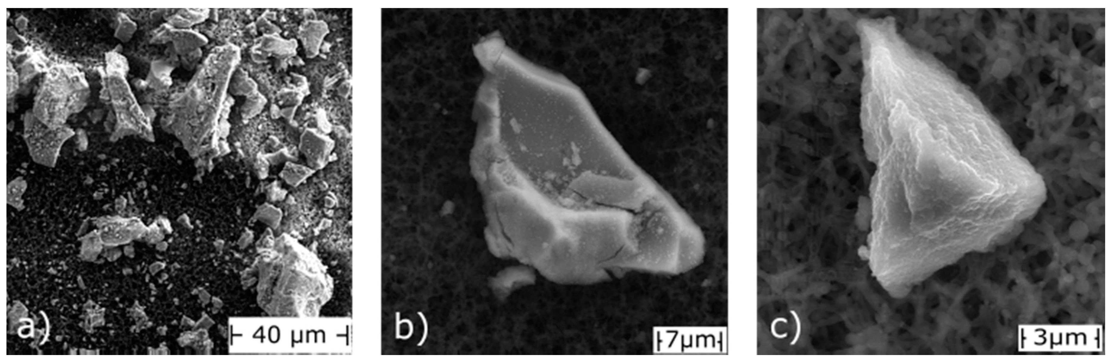
2.1. Characterization of µGFH

GEH Wasserchemie (Osnabrück, Germany) provided µGFH with a water content of ca. 53%. Concentrations of approximately 50 mg/L µGFH were suspended in ultra-pure water and shaken thoroughly to prevent sedimentation during triplicate measurements of the particle size distribution using a particle analyzer (PAMAS SVSS) with a laser diode sensor. Particle volumes were calculated assuming spherical shapes with the particle size as diameter. The specific BET surface areas were determined for selected particle size fractions using nitrogen as described by Gregg and Sing [17] with an AutoSorb-1-MP system (Quantachrome, Boynton Beach, FL, USA). The samples were dried at room temperature (not in an oven) to prevent thermal transformations. The mineral composition of µGFH was determined using X-ray powder diffraction (D2 Phaser, Bruker, Billerica, MA, USA) with a copper anode. Furthermore, the adsorbency was characterized by scanning electron microscopy with energy-dispersive X-ray spectroscopy.

2.2. Fixed Bed Conditioning
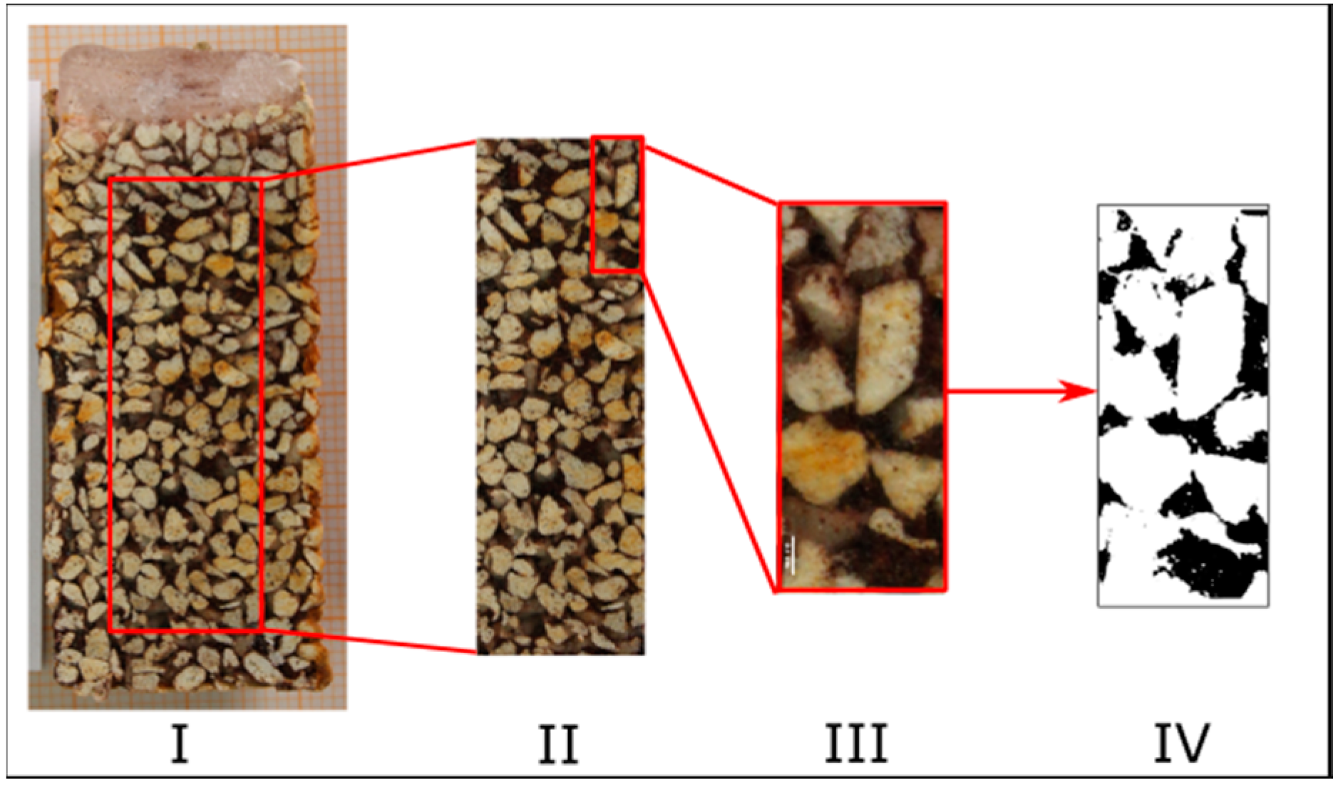
Fixation of µGFH was investigated in small glass columns (24 × 200 mm). The properties of the tested materials (anthracite, coke, pumice and sand) as determined following the respective standards [18] are listed in Table 1. Constant filter bed volumes of 180 cm3 were used for the materials which vary widely in density, grain size and pore volume.
The materials were submerged in deionized water and degassed in vacuum, then rinsed in the columns with deionized water for 24 h to wash out the fine fraction. The pH was adjusted to 8.5 to cause negative surface charges to repulse the negatively charged µGFH particles during filter conditioning. Due to electrostatic repulsion, the particles could penetrate deeply into the fixed bed and the building of a cake layer was prevented.
Conditioning with a highly concentrated µGFH suspension in up- and downstream mode was examined. µGFH was air-dried and suspended in 100 mL deionized water at pH 8.5 (set with NaOH). A pH value above the pHPZC of GFH (7.5) was set to assure negatively charged surface groups and to suppress agglomeration that occurred at pH 7.5.
Conditioning in upstream mode was performed at a velocity of 30 m/h, which was accompanied by a filter bed expansion of approximately 50%. After embedment, mobile µGFH was washed out with 500 mL of deionized water at 5 m/h. To determine the mass of embedded µGFH, the carrier material was removed from the column and washed with deionized water until the supernatant was clear. The µGFH in 20 mL (Vsuspension) of the collected supernatants (Vwash-off) was dissolved by adding defined volumes of 32% HCl (VHCL) and 64% HNO3 (VHNO3) and stirring at 80 °C for one hour. Dissolved iron (cFE) was then quantified with atomic absorption spectroscopy. The mass of µGFH was then calculated with the total volume of the suspension, the dilution from the acids for the disintegration and the iron content of µGFH following Equation (1):
  m µ GFH = c Fe · ( V Suspension + V HCl + V HNO 3 V Suspension ) · 1 w Fe · V wash off  
For image analyses, the filters were conditioned in downstream mode and the effluent was recirculated four times: three times with 5 m/h and one time with a decreased rate of 2.5 m/h.

2.3. Image Analysis

Conditioned columns were frozen at −18 °C for 24 h to analyze the µGFH distribution within the filter bed. The frozen cores were removed from the columns and cut in the frozen state with a circular saw into an upper and lower half (each 5 cm) and subsequently vertically into two parts each (H1 and H2). All conditioning modes were done twofold.
Digital images were taken of each cross-sectional area individually with a Canon EOS 700D camera at constant distance, illumination and angle.
ImageJ [19] was used for picture analyses following the scheme displayed in Figure 1. To exclude wall effects, equally sized rectangles in the middle of the pictures were selected (Step II). The selected sections were divided into twelve subsections to evaluate the homogeneity of the core (Step III). Color thresholds were applied to differentiate between pumice (light color), µGFH (dark brown) and water-filled pore volume and to convert the image into a binary picture (Step IV). The area covered by µGFH was then calculated. Further explanation can be found in the supplementary information.

2.4. Fixed Bed Adsorption Tests

Fixed bed adsorption was studied in cylindrical filter columns (acrylic glass, 2.4 × 100 cm) filled with degassed and extensively flushed pumice to a bed height of 40 cm (ca. 180 mL filter bed). Grain sizes of the carrier material and adsorbent particles were chosen so as to not increase the head loss of the filter. Conditioning was performed in downstream mode (2.5 m/h) with a 30 g/L µGFH suspension (100 mL, pH 8.5). A model solution of phosphate (2 mg/L P), 0.6 g/L NaCl and organic buffer (N,N-Bis(2-hydroxyethyl)-2-aminoethanesulfonic acid, pKa = 7.1, 0.4 mg/L) set to pH 7.0 with NaOH in deionized water was applied for adsorption tests with a flow rate of 2.2 m/h (1 L/h) following experiments by Sperlich et al. [2]. Samples were taken automatically every 3 h at the filter outlet. Orthophosphate was measured via flow injection analysis according to the standard method [20].
Breakthrough data for conventional GFH was taken from Patel [21] for comparison. Due to differences in filter velocity (3 m/h for conventional GFH and 2.2 m/h for µGFH), modelled data is included. Input parameters for modeling are listed in Table S1. The software FAST (fixed bed simulation adsorption tool) has been proven to predict the breakthrough behavior of GFH in numerous studies [2,14,22]. It is based on the homogenous surface diffusion model (HSDM) and combines the mass balance equation with intraparticle transport according to Fick’s second law. The model is described in detail in Sperlich et al. [2].

3. Results

3.1. Physical Characterization

Particle size analyses via laser light extinction of previously wet-sieved µGFH (to below 300 µm) revealed that approximately 30% by volume (or mass, assuming a homogeneous density distribution) is contributed by each of the particle size ranges 0–63 µm, 63–125 µm and 125–250 µm (Figure 2). The fractions of larger particles (250–300 µm) contribute approximately 15% by weight but consist of only comparatively few particles. Hence, the small particles have a great influence on the adsorption kinetics.
Almost identical specific surface areas in the range 299–309 m2/g were determined for the fractions <63 µm, 63–125 µm, 125–250 µm and >250 µm, indicating a negligible impact of the outer particle surface. Badruzzaman et al. [11] reported lower averaged values of 236 ± 9 m2/g for conventional GFH while Sperlich et al. [22] measured values between 229 and 257 m2/g. They [22] showed that surface area could not be linked to grain size and stated that the variation is larger than the measurement uncertainty of the BET method, which was explained by the heterogeneity of the adsorbent media. Other studies reported specific surface areas of up to 300 m2/g [14]. The results obtained in this study are in the upper range of that magnitude. Therefore, no significant rise in equilibrium adsorption capacity of the fine fraction adsorbent in comparison to conventional GFH can be expected.
Mineralogical analyses with powder X-ray diffraction confirmed β-FeOOH as the main constituent of all particles (Figure S1 in the supporting information). Additionally, particles larger than 63 µm showed reflexes which correspond to the chemical structure of FeO (OH, Cl), whereas the spectrum of particles smaller than 63 µm revealed the presence of Fe2O3. Stored particles smaller than 63 µm (from another batch) consisted mainly of hematite. This leads to the assumption that smaller particles are more likely to transform to hematite due to the lack of stabilizing chlorine atoms [14].
The scanning electron microscopic images of µGFH under different magnifications in Figure 3 indicate irregular shapes and the wide range of particle sizes. However, no macro-pores could be observed. Smaller particles attach to bigger particles (Figure 3b). Energy-dispersive X-ray spectroscopy (Figure S2) confirmed, as expected, high contents of iron and oxygen with traces of phosphorus and sulfur. The particles are stable in the pH range 3–14 and can only be dissolved using highly concentrated acids and elevated temperatures which makes them usable for a variety of applications.

3.2. Carrier Material Selection

All four tested granular carrier materials—pumice, coke, anthracite and sand—showed a good fixation of the imbedded µGFH, as after the addition of the µGFH conditioning suspension accompanied with an initial release of particles, only low µGFH concentrations could be found in the column effluent (Figure S3). Sand, however, showed the buildup of a filter cake and no penetration of the µGFH particles into lower filter layers (Figure S4). The intergranular pore sizes of the sand were thus not sufficient for a successful distribution in different filter strata.
The use of coke resulted in a rise in pH of the filtrate to above 12 even after multiple washing cycles. This causes a negative effect on adsorption as most target pollutants like phosphate and arsenate show higher adsorption at pH values below 7 [2,23].
Anthracite showed a slightly lower fixation of µGFH than pumice (95% compared to 97%) but would be equally suitable as a carrier material.
Pumice was chosen as most promising carrier material for the embedment of the fine fraction iron hydroxide as its use did not result in the formation of a filter cake or a change in pH. Furthermore, its light color makes it easily distinguishable from the iron hydroxide particles.
Conditioning in the upstream mode led to a homogenous distribution of µGFH in all carrier materials in small test columns (bed height 10 cm). This could not be reproduced in larger columns (bed height 40 cm), as agglomeration of µGFH particles occurred in parts of the columns which resulted in preferential flow paths of the adsorbate solution. Thus, subsequent conditioning was done in downstream mode.

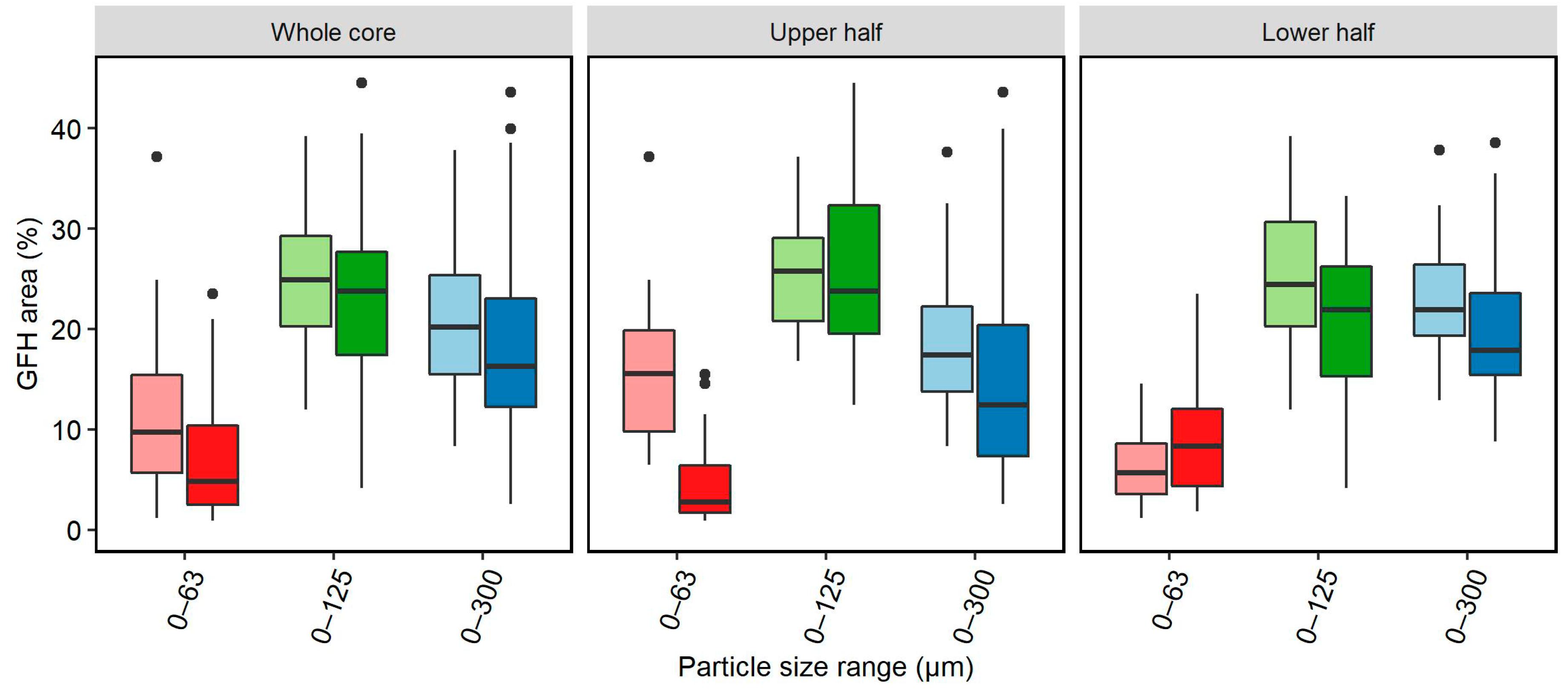
3.3. Optimization of Pumice Loading

To estimate the efficiency of embedment, conditioning suspensions with rising µGFH concentrations (3–50 g/L) were added to pumice-filled columns. Almost complete retention (98%) and loadings of approximately 8 and 20 mg/g were reached with suspensions (50 mL) of 3 and 6 g/L µGFH. The retention was reduced to 67% and 56% when higher suspension concentrations of 24 and 50 g/L, repectively, were filtered. However, the resulting filter loadings were much higher at 48 and 83 mg/g.
Heat maps were drawn to show the fraction of embedded µGFH in differently conditioned columns (Figure 4). Dark colors indicate a high mass of embedded µGFH whereas light colors indicate almost no embedment. Different information can be taken from the maps: how the embedded µGFH is distributed over the core, where it is located and an approximation of how much µGFH (in % volume) can be fixed on the column. The fraction of area filled with µGFH varies between 0% and 45% for µGFH particle sizes 0–125 µm (Figure 4). Higher loadings are found mainly in the middle area of the profile, while loadings are lower near the outer areas of the core. This may indicate wall effects or different flow conditions during column conditioning, which lead to a reduced fixation of the particles in the outer areas. As a result, an inhomogeneous distribution of µGFH over the transverse profile can be seen. In the later adsorption phase, this could lead to preferential flow paths along the areas with lower embedded masses and, therefore, an incomplete exploitation of the adsorbent. It can also be seen that significant differences occur between H1 and H2, which are different layers of the same core. Cross-sectional images and heat maps of all conditioned columns can be found in Figures S5–S13.
A comparative evaluation of all conditioned pumice columns is given in Figure 5. Three different particle size fractions and two additional preparatory steps were tested regarding their effects on µGFH distribution in the fixed bed. The same colors are used for duplicate columns.
• Impact of pH on µGFH distribution:
Equally homogenous distributions are reached with and without setting the pH of the conditioning suspension to 8.5 (Figure 5). Thus, a neutral pH does not lead to agglomeration of particles which affects the embedment of the particles. A small increase in embedded µGFH of approximately 5% is reached with the elevated pH. When washing the carrier material with deionized water without setting the pH beforehand (pH approximately 7), equally high loadings are reached but the duplicate columns differ significantly. Also, the area covered by µGFH varies widely with loadings of approximately 40% in the upper parts of one column and only 10% in the same part of the duplicate column (see Figures S10 and S11). Without setting an elevated pH, pumice particles are unequally charged, which results in nonreproducible loadings with the adsorbent. Thus, the setting of an elevated pH beforehand is essential for homogenous and reproducible loadings.
• Impact of particle sizes:
A variation in particle size leads to big differences in the amount of embedded adsorbent. While the fraction 0–125 µm covers approximately 25% of the area, the fraction 0–63 µm covers less than 10% (Figure 6). Due to the very small particle sizes, interception and sedimentation is limited and the transport efficiency is reduced. This leads to an increased discharge of the particles smaller than 63 µm. Even though the total embedded mass of these particles is smaller, a more homogenous distribution over the filter profile (x coordinate in Figure 6) is reached. The biggest fraction 0–300 µm shows slightly less cross-sectional area covered by µGFH compared with the fraction 0–125 µm (18% in comparison to 25%) and a more inhomogeneous distribution (Figure 7). This corresponds well to experiments with low-concentration conditioning suspensions (1 g/L µGEH), in which 50 times more particles in the range 0–63 µm and 5 times more particles in the range 125–300 µm in comparison to particles in the range 63–125 µm were found in column effluent. The higher concentration of bigger particles in comparison to medium-sized particles in the effluent can be explained by the target surface they offer to shear forces. Therefore, they are more easily detached from the carrier material surface.
• Vertical distribution:
The upper part of the core shows more divergent coverage with µGFH (Figure 7). This leads to the conclusion that the first few centimeters of the columns differ from the deeper layers because either the approaching flow is not laminar or the already embedded particles influence the adhesion of further particles greatly. For particles smaller than 63 µm, a decrease in embedment can be seen over filter depth (Figure 6). For the other size fractions, no clear trend in the amount of embedded µGFH can be observed.
Image analysis is a useful tool to evaluate the embedment of fine particulate adsorbents in a carrier material in water-filled columns. In the case of µGFH embedment in pumice, great differences were found for different preparatory steps and particle sizes. Also, data analysis revealed a broad distribution of GFH embedment per pumice area in different cross sections which complicates interpretation. As a consequence, a big data pool is necessary to obtain statistically reliable results.
However, the data obtained in this study suggest the use of a stock suspension containing the particle size fraction 0–125 (pH 8.5) with pumice, pre-washed at 8.5, as a favored conditioning method for µGFH on pumice, as it led to the most homogeneous distribution with high embedded µGFH masses (approximately 25%).

3.4. Fixed Bed Adsorption

A column conditioned with µGFH according to the method described above leads to comparable adsorption breakthrough curves for phosphate compared with conventional GFH under similar adsorption parameters (pH, flow rate) (Figure 8). Conventional GFH is used in packed fixed-bed filters while in this study µGFH was used as a fine fraction adsorbent embedded in a carrier material, which results in a need for a substitute for bed volume as the reference value. For better comparability, the increase of phosphate in column effluent is plotted against the specific throughput (L/g) with regard to the applied adsorbent. As no data with identical flow rates was available for conventional GFH, a modelled curve was added for comparability. Probably due to retarded phosphate diffusion to particles not exposed to the flow, all displayed breakthrough curves vary significantly from the ideal s-shaped breakthrough curve. This known effect of conventional GFH could not be improved by the use of fine particulate adsorbent and is explained by a limitation of adsorption through slow surface diffusion.
By using embedded µGFH, no complete holdback of phosphate could be achieved since from the start of the experiment small concentrations of approximately 0.1 mg/L were measured in the filter effluent. The slope of the breakthrough curve shows a slower increase in concentration in comparison to conventional GFH. As shown above, a homogeneous distribution of µGFH on the carrier material is hard to achieve. As a consequence, preferential flow paths are established and the adsorbent is unequally loaded with the target compounds. In areas with high amounts of embedded µGFH, the outer areas are likely to adsorb while the inner grains do not come into contact with the target pollutants. At 80% breakthrough, loadings of 24 mg/g P are reached for the fine fraction, while conventional GFH reaches 24 mg/g P at 100% breakthrough [21]. The embedment of the adsorbent did not lead to an increase of head loss in the filter.
Removal of exploited µGFH by backwash and successful replacement with fresh µGFH is a requirement for successful utilization of µGFH in fixed-bed filters. Furthermore, it is preferable to remove the loaded adsorbent as completely as possible to raise the embedding capacity for fresh adsorbent. Tests revealed that multiple conditioning of pumice with µGFH leads to comparable loadings of the carrier material (60 ± 4 mg µGFH/g pumice) and similar phosphate adsorption.
Compared with the use of conventional GFH, the described process is space and cost efficient, as existing rapid filters can be upgraded for heavy metal or phosphate removal. As the adsorbent is a by-product in the production process of conventional GFH and is currently disposed, its use reduces waste, is resource-efficient and is sustainable. Possible applications of this process are highly dependent on the target pollutant but include water restoration and drinking and waste water treatment.

4. Conclusions

This study characterized an iron hydroxide fine fraction adsorbent, named µGFH and introduced a method using image analyses for the evaluation of embedment of fine fraction particles on carrier materials in water-saturated filter columns. The main findings are as follows:
  • BET analyses quantified surface areas of 300 m2/g for the fine fraction, equivalent to those of conventional GFH. Therefore, similar equilibrium adsorption capacities can be expected. The material consists of 30% (by mass) particles below 63 µm and very few particles above 120 µm.
  • For the utilization of µGFH in fixed-bed filtration, pumice proved to be a good carrier material. High embedment of the adsorbent (approximately 60 mg/g) and a homogeneous distribution could be observed when the pumice was pre-washed with deionized water (pH set to 8.5). The use of a concentrated stock suspension containing particle sizes 0–125 µm with pH set to 8.5 led to a homogeneous distribution on the carrier material.
  • A method of image analysis of cross sections of frozen filter bed cores proved applicable for distribution analysis of fine fraction particle embedment in filter columns filled with a carrier material.
  • A laboratory-scale fixed-bed filter with embedded µGFH showed breakthrough curves for phosphate similar to those of conventional GFH fixed-bed adsorbers. The use of µGFH did not lead to accelerated intra-particle diffusion. Loadings of 24 mg/g P were reached.

Supplementary Materials

The following are available online at https://www.mdpi.com/2073-4441/10/10/1324/s1, Figure S1: XRD diffractograms of (a) 63–300 µm and (b) 0–63 µm µGFH particle sizes with vertical lines indicating reflex positions, Figure S2: Energy dispersive X-ray spectrum of µGFH with major peaks for iron (Fe), oxygen (O), phosphor (P), sulfur (S), silicon (Si) and carbon (C, used for coating to enhance electric conductivity), Figure S3: Cumulative masses of µGFH in column effluent over treated volume for different carrier materials with downstream conditioning, Figure S4: Conditioned columns with (a) anthrazite, (b) pumice, (c) filter coke and (d) sand, Figure S5: Photographs of vertical cross-sections of frozen filter beds (pH 8.5 of the conditioning suspension and during pre-wash) loaded with µGFH particles in the size range 0–63 µm (left) and resulting/corresponding distribution patterns obtained by image analyses as described in section S1, Core A, Figure S6: Photographs of vertical cross-sections of frozen filter beds (pH 8.5 of the conditioning suspension and during pre-wash) loaded with µGFH particles in the size range 0–63 µm (left) and resulting/corresponding distribution patterns obtained by image analyses as described in section S1, Core B, Figure S7: Photographs of vertical cross-sections of frozen filter beds (pH 8.5 of the conditioning suspension and during pre-wash) loaded with µGFH particles in the size range 0–125 µm (left) and resulting/corresponding distribution patterns obtained by image analyses as described in section S1, Core A, Figure S8: Photographs of vertical cross-sections of frozen filter beds (pH 8.5 of the conditioning suspension and during pre-wash) loaded with µGFH particles in the size range 0–300 µm (left) and resulting/corresponding distribution patterns obtained by image analyses as described in section S1, Core A, Figure S9: Photographs of vertical cross-sections of frozen filter beds (pH 8.5 of the conditioning suspension and during pre-wash) loaded with µGFH particles in the size range 0–300 µm (left) and resulting/corresponding distribution patterns obtained by image analyses as described in section S1, Core B, Figure S10: Photographs of vertical cross-sections of frozen filter beds (pH 6 of the conditioning suspension and pH 8.5 during pre-wash) loaded with µGFH particles in the size range 0–125 µm (left) and resulting/corresponding distribution patterns obtained by image analyses as described in section S1, Core A, Figure S11: Photographs of vertical cross-sections of frozen filter beds (pH 6 of the conditioning suspension and pH 8.5 during pre-wash) loaded with µGFH particles in the size range 0–125 µm (left) and resulting/corresponding distribution patterns obtained by image analyses as described in section S1, Core B, Figure S12: Photographs of vertical cross-sections of frozen filter beds (pH 8.5 of the conditioning suspension and pH 7 during pre-wash) loaded with µGFH particles in the size range 0–125 µm (left) and resulting/corresponding distribution patterns obtained by image analyses as described in section S1, Core A, Figure S13: Photographs of vertical cross-sections of frozen filter beds (pH 8.5 of the conditioning suspension and pH 7 during pre-wash) loaded with µGFH particles in the size range 0–125 µm (left) and resulting/corresponding distribution patterns obtained by image analyses as described in section S1, Core B, Table S1: Input parameters for Fixed bed adsorption simulation tool.

Author Contributions

The article was written by I.H. within her Ph.D. project, with supervision by A.S.R. and M.J.

Funding

The current research as part of the German–Israeli project AdsFilt (02WIL1389) is funded by the German Ministry of Education and Research (BMBF) within the framework of the German–Israeli water technology cooperation.

Acknowledgments

We acknowledge support by the German Research Foundation and the Open Access Publication Funds of TU Berlin.

Conflicts of Interest

The authors declare no conflict of interest.

References

  1. Driehaus, W.; Jekel, M.; Hildebrandt, U. Granular ferric hydroxide—A new adsorbent for the removal of arsenic from natural water. J. Water Serv. Res. Technol. 1998, 47, 30–35. [Google Scholar] [CrossRef]
  2. Sperlich, A.; Schimmelpfennig, S.; Baumgarten, B.; Genz, A.; Amy, G.; Worch, E.; Jekel, M. Predicting anion breakthrough in granular ferric hydroxide (GFH) adsorption filters. Water Res. 2008, 42, 2073–2082. [Google Scholar] [CrossRef]
  3. Sperlich, A.; Werner, A.; Genz, A.; Amy, G.; Worch, E.; Jekel, M. Breakthrough behavior of granular ferric hydroxide (GFH) fixed-bed adsorption filters: Modeling and experimental approaches. Water Res. 2005, 39, 1190–1198. [Google Scholar] [CrossRef] [PubMed]
  4. Tan, K.L.; Hameed, B.H. Insight into the adsorption kinetics models for the removal of contaminants from aqueous solutions. J. Taiwan Inst. Chem. Eng. 2017, 74, 25–48. [Google Scholar] [CrossRef]
  5. Genz, A.; Baumgarten, B.; Goernitz, M.; Jekel, M. NOM removal by adsorption onto granular ferric hydroxide: Equilibrium, kinetics, filter and regeneration studies. Water Res. 2008, 42, 238–248. [Google Scholar] [CrossRef] [PubMed]
  6. Ruhl, A.S.; Altmann, J.; Zietzschmann, F.; Meinel, F.; Sperlich, A.; Jekel, M. Integrating Micro-Pollutant Removal by Powdered Activated Carbon into Deep Bed Filtration. Water Air Soil Pollut. 2014, 225, 1877. [Google Scholar] [CrossRef]
  7. Altmann, J.; Ruhl, A.S.; Sauter, D.; Pohl, J.; Jekel, M. How to dose powdered activated carbon in deep bed filtration for efficient micropollutant removal. Water Res. 2015, 78, 9–17. [Google Scholar] [CrossRef] [PubMed]
  8. Haberer, K.; Normann-Schmidt, S. The Haberer Process: Combining Contact Flocculation, Filtration and PAC Adsorption. J. Am. Water Works Assoc. 1991, 83, 82–89. [Google Scholar] [CrossRef]
  9. Löwenberg, J.; Zenker, A.; Krahnstöver, T.; Boehleret, M.; Baggenstosal, M.; Koch, G.; Wintgens, T. Upgrade of deep bed filtration with activated carbon dosage for compact micropollutant removal from wastewater in technical scale. Water Res. 2016, 94, 246–256. [Google Scholar] [CrossRef] [PubMed]
  10. Huang, Y.; Yang, J.-K.; Keller, A.A. Removal of Arsenic and Phosphate from Aqueous Solution by Metal (Hydr-)oxide Coated Sand. ACS Sustain. Chem. Eng. 2014, 2, 1128–1138. [Google Scholar] [CrossRef] [Green Version]
  11. Badruzzaman, M.; Westerhoff, P.; Knappe, D.R.U. Intraparticle diffusion and adsorption of arsenate onto granular ferric hydroxide (GFH). Water Res. 2004, 38, 4002–4012. [Google Scholar] [CrossRef] [PubMed]
  12. Bhatnagar, A.; Choi, Y.; Yoon, Y.; Shin, Y.; Jeon, B.-H.; Kang, J.-W. Bromate removal from water by granular ferric hydroxide (GFH). J. Hazard. Mater. 2009, 170, 134–140. [Google Scholar] [CrossRef] [PubMed]
  13. Kumar, E.; Bhatnagar, A.; Ji, M.; Jung, W.; Lee, S.-H.; Kim, S.-J.; Lee, G.; Song, H.; Choi, J.-Y.; Yang, J.-S.; et al. Defluoridation from aqueous solutions by granular ferric hydroxide (GFH). Water Res. 2009, 43, 490–498. [Google Scholar] [CrossRef] [PubMed]
  14. Bahr, C. Entfernung von Uran aus Trinkwasser durch Adsorption an Granuliertem Eisenhydroxid (GEH). Ph.D. Thesis, Technical University Berlin, Berlin, Germany, December 2012. (In German). [Google Scholar]
  15. Jekel, M. Wasseraufbereitung: Grundlagen und Verfahren, 2nd ed.; Czekalla, C., Ed.; Deutscher Industrieverlag: München, Deutschland, 2017; Volume 6. (In German) [Google Scholar]
  16. Saha, B.; Bains, R.; Greenwood, F. Physicochemical characterization of granular ferric hydroxide (GFH) for arsenic(V) sorption from water. Separ. Sci. Technol. 2005, 40, 2909–2932. [Google Scholar] [CrossRef]
  17. Gregg, S.J.; Sing, K.S. Adsorption, Surface Area and Porosity, 2nd ed.; Acad. Press: London, UK, 1982. [Google Scholar]
  18. Deutsches Institut für Normung e.V. Products Used for Treatment of Water Intended for Human Consumption—Inorganic Supporting and Filtering Materials—Methods of Test (EN 12902). 2005. Available online: https://www.beuth.de/de/norm/din-en-12902/72862226 (accessed on 4 September 2018).
  19. Schindelin, J.; Arganda-Carreras, I.; Frise, E.; Kaynig, V.; Longair, M.; Pietzsch, T.; Preibisch, S.; Rueden, C.; Saalfeld, S.; Rueden, C.; et al. Fiji: An open-source platform for biological-image analysis. Nat. Methods 2002, 9, 676–682. [Google Scholar] [CrossRef] [PubMed]
  20. Deutsches Institut für Normung e.V. Wasserbeschaffenheit—Bestimmung von Phosphor—Photometrisches Verfahren Mittels Ammoniummolybdat—Methods of Test (EN 6878). Available online: https://www.beuth.de/de/norm/din-en-iso-6878/71312882 (accessed on 4 September 2018).
  21. Patel, A. Desorption von Phosphat in GEH-Festbettfiltern: Einfluss von pH-Wert und Calcium. Master’s Thesis, Technische Universität Berlin, Berlin, Germany, 2016. (In German). [Google Scholar]
  22. Sperlich, A. Phosphate Adsorption onto Granular Ferric Hydroxide (GFH) for Wastewater Reuse. Ph.D. Thesis, Technische Universität Berlin, Berlin, Germany, July 2010. [Google Scholar]
  23. Kersten, M.; Karabacheva, S.; Vlasova, N.; Branscheid, R.; Schurk, K.; Stanjek, H. Surface complexation modeling of arsenate adsorption by akagenéite (β-FeOOH)-dominant granular ferric hydroxide. Colloid Surf. A 2014, 448, 73–80. [Google Scholar] [CrossRef]
Figure 1. Picture analyses with ImageJ with (I) photograph of the frozen and cut column, (II) core excluding wall effects, (III) subsection (1 of 12) and (IV) converted binary image.
Water 10 01324 g001
Figure 2. Particle size distribution of fine fraction GFH (µGFH) by volume estimated from particle sizes determined using a particle analyzer; numbers indicate detected particle numbers (in % of the total number) of the fraction.
Water 10 01324 g002
Figure 3. Scanning electron microscopic images of (a) unfractionated µGFH bulk material, (b) an individual particle with attached fines and (c) a small particle deposited on a cellulose nitrate membrane.
Water 10 01324 g003
Figure 4. Vertical cross sections of the upper and lower parts of a frozen core (left) and resulting heat maps with regard to the accumulation of µGFH particles (0–125 µm) in the pores of pumice.
Water 10 01324 g004
Figure 5. Influence of preparatory steps on area covered by µGFH; same colors indicate duplicate columns.
Water 10 01324 g005
Figure 6. Vertical and horizontal distributions of µGFH in cross sections depending on particle size.
Water 10 01324 g006
Figure 7. Cross-sectional area fractions covered by µGFH in vertical distribution; same colors indicate duplicate columns.
Water 10 01324 g007
Figure 8. Phosphate breakthrough curve in embedded µGFH (flow 2.2 m/h) compared to conventional GFH (3 m/h), modelled data (2.2 m/h) and the ideal breakthrough curve without surface diffusion limitation (pH 7, buffered, c0(P) = 2 mg/L).
Water 10 01324 g008
Table 1. Physical characteristics of the filter materials.
MaterialProduct (Supplier)Main ComponentParticle Size (mm)Bulk Density (kg/m3)Grain Density (g/cm3)
AnthraciteHydroanthrasit-P (Rheinkalk Akdolit)Carbon (92%)1.4–2.57181250
CokeFilter coke H Type II (Evers GmbH)Carbon (88%)1.4–2.55231667
PumiceEVERZIT BI (Evers GmbH)SiO2 (55%)0.8–1.53751250
SandQuartz sand (Sand-Schulz)SiO2 (98%)1.0–2.014852625

