Article

Design and Season Influence Nitrogen Dynamics in Two Surface Flow Constructed Wetlands Treating Nursery Irrigation Runoff

Department of Plant and Environmental Sciences, Clemson University, Clemson, SC 29637-0310, USA
Water 2018, 10(1), 8; https://doi.org/10.3390/w10010008
Submission received: 1 November 2017 / Revised: 18 December 2017 / Accepted: 20 December 2017 / Published: 23 December 2017
(This article belongs to the Special Issue Treatment Wetlands for Nutrient Removal)

Abstract

:
Constructed wetlands (CWs) are used to remediate runoff from a variety of agricultural, industrial, and urban sources. CW remediation performance is often evaluated at the laboratory scale over durations less than one year. The purpose of this study was to characterize the effect of CW design (cell depth) and residence time on nitrogen (N) speciation and fate across season and years in two free water surface wetlands receiving runoff from irrigated plant production areas at an ornamental plant nursery. Water quality (mg·L−1 of nitrate, nitrite, and ammonium, dissolved oxygen and oxidation reduction potential) was monitored at five sites within each of two CWs each month over four years. Nitrate-N was the dominant form of ionic N present in both CWs. Within CW1, a deep cell to shallow cell design, nitrate comprised 86% of ionic N in effluent. Within CW2, designed with three sequential deep cells, nitrate comprised only 66% of total N and ammonium comprised 27% of total N in CW2 effluent. Differences in ionic N removal efficacies and shifts in N speciation in CW1 and CW2 were controlled by constructed wetland design (depth and hydraulic retention time), the concentration of nutrients entering the CW, and plant species richness.

1. Introduction

Constructed wetlands (CWs) are engineered biological treatment systems used by agricultural producers [1,2,3], stormwater managers in urban and suburban communities [4,5,6], wastewater treatment plants [7,8,9], industry [10,11], and landfills to remove contaminants from leachate, stormwater runoff and wastewater using physical (settling), chemical (sorption and oxidation reduction potential) and biological (microbial and plant uptake) treatment processes. Design of CWs is a critical part of their function, as hydrology (free water surface, horizontal subsurface flow, vertical subsurface flow, and floating), residence time, and vegetation (emergent, floating, and submerged) interact to regulate CW capacity to mitigate contaminants [11,12,13,14].
Many studies evaluating contaminant remediation efficacy within CWs are laboratory and mesocosm-scale experiments [1,10,15]. Laboratory and mesocosm scale studies are highly useful to parameterize factors that influence remediation efficacy for specific contaminants and design parameters because experimental replication at a smaller scale is less expensive. Extrapolation of laboratory scale CW functionality to field-scale applications typically result in over-estimation of contaminant remediation potential and may inadequately simulate changes in plant growth and physicochemical parameters within the CW [16,17]. Laboratory scale experiments are a critical step toward determining how design factors influence remediation efficacy; however, only field-scale applications permit accurate validation of predicted remediation efficacy as influenced by specific design factors.
Constructed wetland performance depends upon the age of the system and composition of plant species established within the CW [9,18,19,20]. Plant species composition directly affects the quality of organic carbon available to support microbial communities processing nutrient and carbon sources within water for energetic resources (oxidation reduction potential (ORP), availability and quality of electron donors) during aerobic and anaerobic degradation processes [13,21,22,23,24]. Agricultural wastewater treatment typically focuses on management of sediment, nutrients, and pesticides to minimize potential for environmental degradation [1,25,26]. Agricultural applications of CWs for runoff treatment include both free water surface and horizontal subsurface flow [2,27].
Free water surface wetlands (FWS) are designed to have areas of open water and are similar in appearance to natural wetlands [13]. Design depth of FWS is typically 0.30 m [28]; this depth helps to create the anaerobic conditions that facilitate denitrification [13]. Deep cells (0.6 to 1.2 m) are used in design of FWS to: (1) enhance mixing and limit potential for plug flow through the CW; and (2) provide opportunity for re-aeration of water, increasing dissolved oxygen [29]. Debate exists within the literature as to whether incorporation of deep zones only serves to create habitat for wildlife or whether nutrient remediation can be enhanced, via creation of aerobic and anaerobic zones [13,28,29].
Precise measurement of the ionic N (ionN) species (nitrate (NO3-N), nitrite (NO2-N), and ammonium (NH4+-N)) are needed for accurate modeling to characterize CW efficacy for N remediation; nitrogen speciation should be quantified over multiple seasons and years at the field scale [24,30]. This study is unique in that it provides a case study where two FWS CWs were monitored over a four-year period, enabling characterization of seasonal variations in ionN speciation as influenced by CW design. The goal of this research was to characterize the effect of CW design (cell depth) and residence time on nitrogen (N) speciation and fate both across season and years in two free water surface wetlands receiving runoff from irrigated plant production areas at an ornamental plant nursery.

2. Materials and Methods

2.1. Study Site

2.1.1. Constructed Wetland 1

Constructed Wetland 1 (CW1) is a 3.8-ha, two-stage, vegetated, free water surface CW that receives excess runoff from a 48.6-ha horticultural production area (drainage area 1) in Cairo, GA (Figure 1A,B). Plants produced in drainage area 1 are woody (Acer spp., Lagerstroemia spp., Magnolia spp., Quercus spp., Rosa spp., Salix spp., etc.) plant materials in containers sizes #5 to #15 (20 to 60 L substrate volumes). Plants grown in drainage area 1 typically require multiple seasons on-site at the nursery prior to sale and receive liquid fertilization, at certain times of year (typically early spring (March–April) and late summer (August)), and are also top-dressed with a controlled release fertilizer for maintenance-level nutrition. The vegetation community of plants in CW1 is described in White et al. [31]. CW1 was planted with 6 wetland species (Schoenoplectus californicus, Panicum hemitomon, Pontederia cordata, Canna flaccida, Sagittaria latifolia, and Juncus effusus var. solutus) in 1997; by 2006, more than 141 distinct plant species were reported colonizing CW1 [31].
Runoff from production beds drains into a 0.46-km flow-control channel that drains into a 0.4-ha retention pond (Figure 1B). The runoff is then pumped from the retention pond into Stage 1. Stage 1 has an average depth of 76.2 cm and a theoretical hydraulic retention time (HRT) of 3.5 days. Water flows into Stage 1 through 6.4-cm polyvinyl chloride (PVC) pipes, and inflow rates range from 250 to 350 L/min dependent upon daily pump flow rate. Two earthen dikes extend to within approximately 9.1 to 12.2 m from the end of the two cells in Stage 1, dividing each cell into three sections in an open channel, which is 121.9-cm deep, and then is gravity fed through 15.2-cm (6 in) PVC drainpipes into the second stage of the CWs. Stage 2 of the CW1 is also divided into three sections and joined at the discharge end (6.1 m to 9.1 m) to provide a mixing zone before gravity-fed release into the 0.38-km discharge channel. The depth of the two cells in Stage 2 average 20.3-cm deep and have a theoretical 2 day HRT. Both stages combined result in a theoretical 5.5 day HRT. Water flows through the discharge channel and through two stilling ponds, to permit settling of remaining suspended sediments. Water exits the stilling ponds and ultimately leaves the drainage area 1.

2.1.2. Constructed Wetland 2

Constructed Wetland 2 (CW2) is a 1.8-ha, three-stage, vegetated, free water surface CWs that receives excess runoff from an 87.7-ha horticultural production area (drainage area 2), at the same ornamental plant nursery (Figure 1A,C). Plants produced in drainage area 2 are small woody (Abelia spp., Berberis spp., Buddleia spp., Juniperus spp., Hydrangea spp., Ilex spp., Rhaphiolepis spp., Rosa spp., etc.) and herbaceous plant materials (Coreopsis spp., Pennisetum spp., Hemerocallis spp., Hosta spp., Iris spp., Rudbeckia spp., and Scabiosa spp.) in container sizes #1 to #5 (3.8 L to 19 L volumes). Plants grown in drainage area 2 typically require a single season on-site at the nursery prior to sale and are fertilized at potting with a slow release fertilizer that is mixed in the potting substrate. CW2 was constructed in 2008 and was planted with 4 plant species (Pontederia cordata, Schoenoplectus californicus, Typha latifolia, and Hydrocotyle umbellata).
Runoff from production beds drains into a 0.69-km flow-control channel that drains into a 0.57-ha retention pond (Figure 1C). The runoff is then pumped from the retention pond into the wetland cells that were designed to have a theoretical HRT of 1 day per stage and an average depth of 80-cm. Stage 1 is 0.4-ha cell. Water flows into Stage 1 through 6.4-cm polyvinyl chloride (PVC) pipes, and inflow rates range from 250 to 350 L/min dependent upon daily pump flow rate. Water is then gravity fed through 15.2-cm PVC drainpipes into the Stage 2 of the CW. Stage 2 is a 0.74-ha cell. Water is then gravity fed from Stage 2 through 15.2-cm PVC drainpipes into Stage 3. Stage 3 is a 0.64-ha cell. Water is then gravity fed into the sedimentation pond (0.06 ha) and flows via gravity through the final stilling pond (0.02 ha), prior to release from drainage area 2.

2.1.3. Hydraulic Loading into CW1 and CW2

Daily water flow into the both CW1 and CW2 varied over the study (May 2009–July 2013). In May 2010, the meters recording volume pumped from retention ponds into CWs ceased to work, and their function was not restored; thus, loading rates for nutrients could not be reliably calculated. Historical flow rates (L/day) into CW1 from 2003 to 2006 were 266,241 ± 550,882 (January), 266,241 ± 550,882 (February), 2,072,096 ± 272,784 (March), 2,733,227 ± 561,913 (April), 2,187,867 ± 258,999 (May), 1,410,298 ± 33,518 (June), 4,570,626 ± 1,869,624 (July), 2,808,072 ± 565,272 (August), 4,011,647 ± 967,368 (September), 2,504,565 ± 559,097 (October), 2,780,548 ± 568,771 (November), and 2,012,136 ± 581,862 (December). Throughout the remainder of this article, sampling sites within each of the CWs are referred to via the site key number in Table 1.

2.2. Water Quality Monitoring

Water samples were collected between 08:30 a.m. and 11:00 a.m. (in the same order) on a monthly basis from 2009 to 2013 (January n = 3, February n = 2, March n = 4, April n = 2, May n = 3, June n = 4, July n = 4, August n = 2, September n = 3, October n = 2, November n = 1, and December n = 2). Samples were collected at 26 sites in CW1 and 17 sites in CW2 from May 2009 to November 2011. Thereafter, based on similarity of constituent analyses among sampling sites, composite samples (water from the same sub-sites was collected and mixed to create a single sample from which nutrient analyses were performed) were collected, such that 7 composite samples were collected from CW1 and 7 composite samples were collected from CW2 from December 2011 to July 2013 (Table 1).
Water samples were grab samples (250 mL collected 8 times sequentially for a total of 2 L from each sampling site, composite samples were mixed after collection) representing a particular time and location. Dissolved oxygen (DO, mg/L) and oxidation reduction potential (ORP, mV) were also measured directly after samples were collected using hand-held YSI Environmental ProODO and Professional Plus handheld meters, respectively (YSI Environmental, Yellow Springs, OH, USA). Samples for anion analyses were filtered through 0.45 µm polytetrafluoroethylene (PTFE) membrane filters into 1.5 mL ion chromatography (IC) vials and stored at 4 °C until analysis with a Dionex AS10 IC with AS50 auto-sampler (Dionex Corp., Sunnyvale, CA, USA). Samples were analyzed for nitrite (NO2-N), nitrate (NO3-N) via IC and for ammonium (NH4+-N) using an Orion Ammonia Selective Electrode 95−12 (Thermo Electron Corp., Beverly, MA, USA).

2.3. Statistical Analyses

Constructed wetland water samples were analyzed for ionic N (ionN = NO2-N + NO3-N + NH4+-N). Concentration (mg·L−1) were averaged for each month by site. The percent of ionN were also calculated each month, by site Equation (1).
%   of   ionic   nitrogen   =   NO 2 - N   ( or   NO 3 - N   or   NH 4 - N ) NO 2 - N   +   NO 3 - N +   NH 4 - N
The percent of NO2-N, NO3-N, or NH4+-N contributing to ionN varied somewhat from year-to-year; thus, it was possible to have calculated percentages of total N > 100%. Total N removal efficacies were calculated on a percentage basis for Sites 2 to 5 within CW1 and CW2 as related to influent (average of Sites 1.1, 1.2. and 1.3) concentrations Equation (2).
Ionic   nitrogen   removed   ( % )   =   ( 1   Effluent   ( mg · L 1 ) Influent   ( mg · L 1 ) )   ×   100
When appropriate, comparisons among dependent (month and site) variables were made using Distribution, Standard Least Squares, Mixed Model, or Generalized Regression models using JMP® Pro 13.2.0 (SAS Institute, Inc., Cary, NC).

3. Results

3.1. Nitrogen Dynamics in CW1

Ammonium and nitrate were the dominant forms of nitrogen in waters flowing from Sites 1.1, 1.2, and 1.3 into CW2 Site 2 (Figure 2, Table 2). Seasonal peaks in ionN concentration entering the wetland were evident, with high nutrient concentrations flowing into the wetlands from March to July (p < 0.001). Peaks in ionN concentration detected from March to July correlate well with peaks in plant production cycle, when supplemental fertilization occurs to support nursery crop growth. Ammonium concentrations are greater in the inflow ditch than in the retention pond or inflow to CW1 from April (p = 0.031) to July (p = 0.019). This is likely due to inflow ditch design, and the presence of aeration structures (small waterfall steps) specifically designed to aerate water and promote nitrification processes. The relative proportion of ammonium to ionN did not differ within month among inflow sites (p = 0.395), but differed among months, as did concentration (p < 0.001).
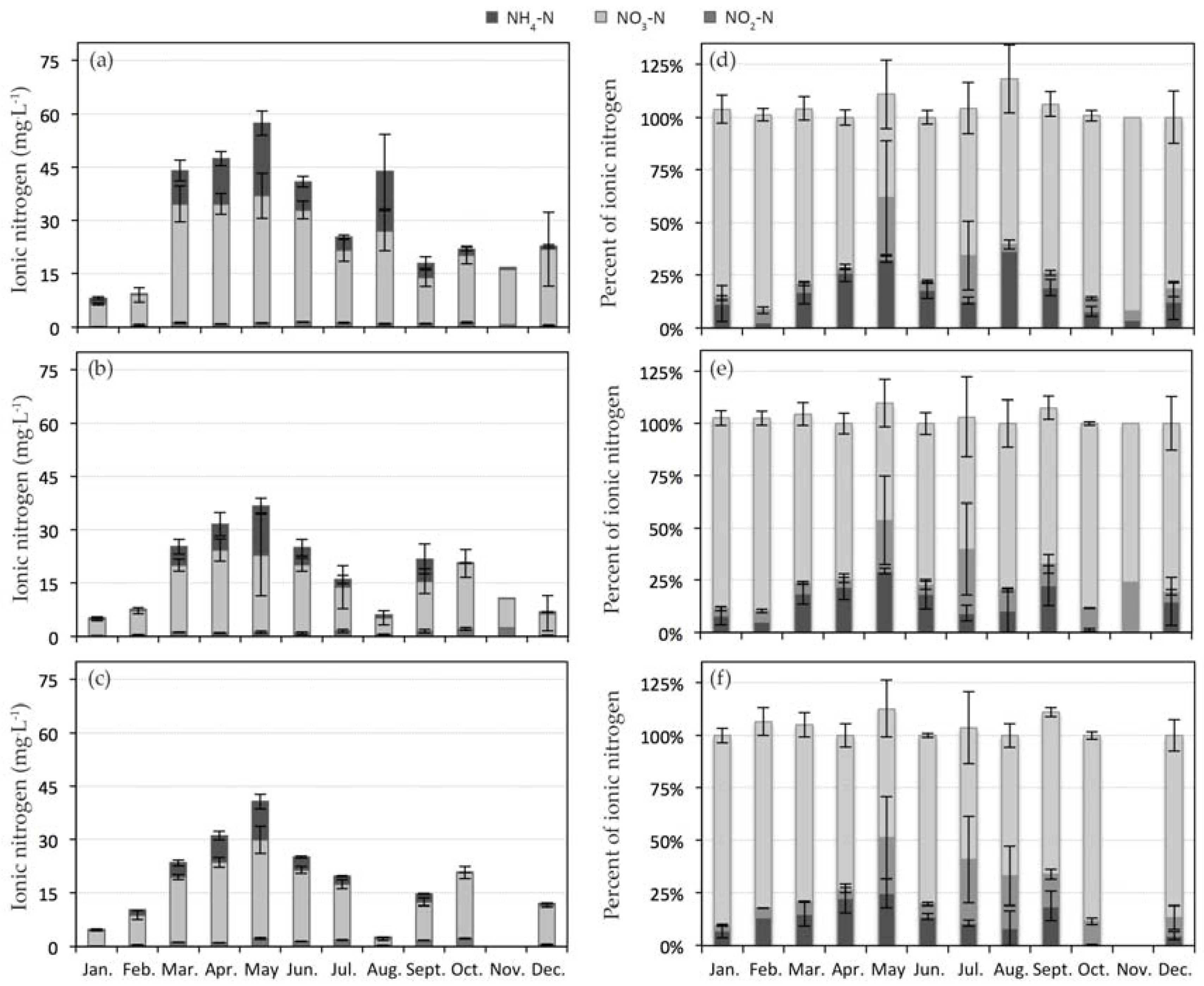
Within CW1 as production runoff flowed from Site 2 to Site 5, the concentration of total N generally diminished (Figure 3). Total N yearly average concentrations were 11.3 ± 0.88 mg·L−1 in Site 2, 8.47 ± 0.75 mg·L−1 in Site 3, 8.55 ± 1.50 mg·L−1 in Site 4, and 7.94 ± 1.06 mg·L−1 in Site 5. The composition of effluent changed, with nitrate percent increasing further 86.4 ± 1.2% (compared with ~78% in Sites 1.1–1.3) of ionN. Ammonium and nitrite comprised 8.3 ± 1.2% and 5.6 ± 1.1%, respectively, of the total N exiting CW1. It is pertinent to note missing values for Sites 2–4, as the pump feeding CW1 was not functioning when we sampled, thus samples were only collected when water was present (Site 5—the stilling pond).
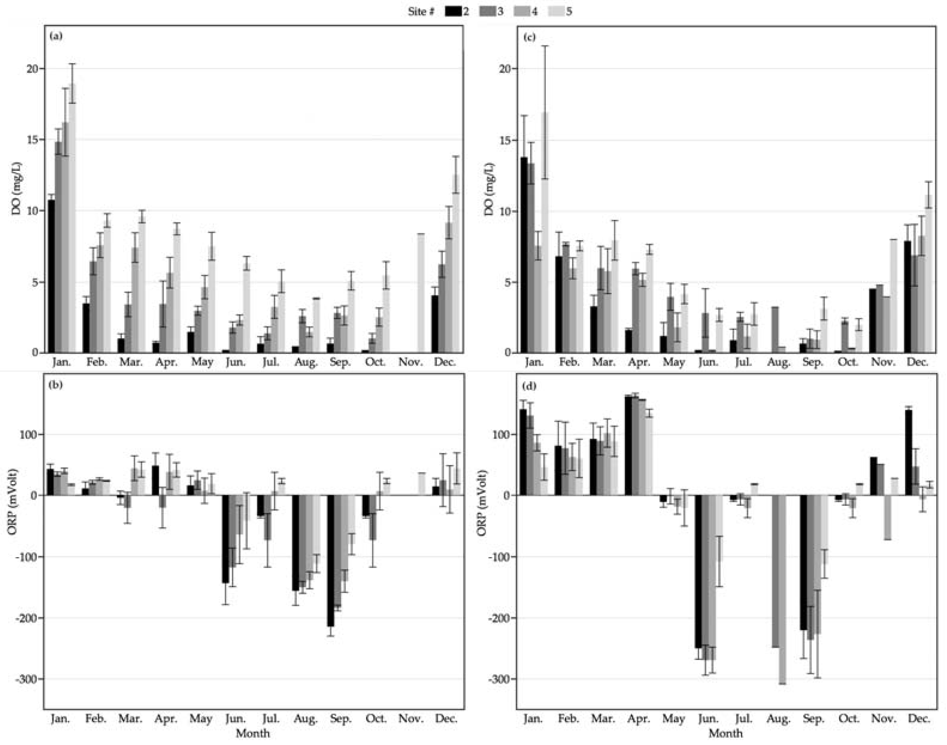
Within CW1, as production runoff flowed from Site 2 to Site 5, DO and ORP were also dynamic (Figure 4). In general, DO concentrations were lowest in Site 2 (1.58 ± 0.24 mg·L−1), with incremental increases for Site 3 (3.35 ± 0.37 mg·L−1), Site 4 (4.85 ± 0.55 mg·L−1), and Site 5 (7.75 ± 0.50 mg·L−1). Constructed Wetland 1 was designed to promote this incremental increase in dissolved oxygen, both to ensure adequate nitrate reduction (Sites 2 and 3) and to ensure DO concentrations exiting the system were high enough to sustain aquatic life (Sites 4 and 5).
Oxidation reduction potential dynamics yield insight into the energetics of microbial communities within CW1. The relative availability of preferred electron donors for use by microbial populations in processing carbon are reflected by changes in ORP. In Site 2, nitrate concentrations were generally higher than the other sites, and dissolved oxygen concentrations were typically lower. In months where CW1 nitrogen processing was particularly efficient (June, July, August, and September), Site 2 ORP was more negative than for other sites, indicating that nitrate was no longer the dominant electron donor, and other anions such as manganese, iron, or sulfate were serving as the energetic donors for carbon processing. In months where either DO remained high (December–January) or excess nitrogen remained in the system (April, May, and October), microbial communities still retained access to nitrate or oxygen as electron donors for carbon processing.
Nitrogen removal efficacy in CW1 averaged 56.9 ± 2.2% in Site 2, 65.1 ± 2.8% in Site 3, 65.0 ± 4.2% in Site 4, and 65.3 ± 4.1% in Site 5. From November to February, the concentration of nitrogen in waters flowing into CW1 was minimal, as no supplemental fertilizer was applied to nursery crops. Nutrients entering CW1 were likely those leached from containers during irrigation or storm events. Nitrogen removal efficacy in CW1 was variable from November to February (Figure 5). The months when CW1 was least efficient at removing ionN correlated with the lowest ionN concentrations entering CW1 (p < 0.001). Thus, even though ionN removal efficacy ranged from export (-31.8%) to removal (54.2%) in December and January, NO3-N concentrations in effluent from CW1 met (9.74 ± 1.73 mg·L−1 NO3-N) or was substantially lower than (6.15 ± 1.22 mg·L−1 ionN) US EPA drinking water quality standard of <10 mg·L−1 NO3-N [32].

3.2. Nitrogen Dynamics in CW2

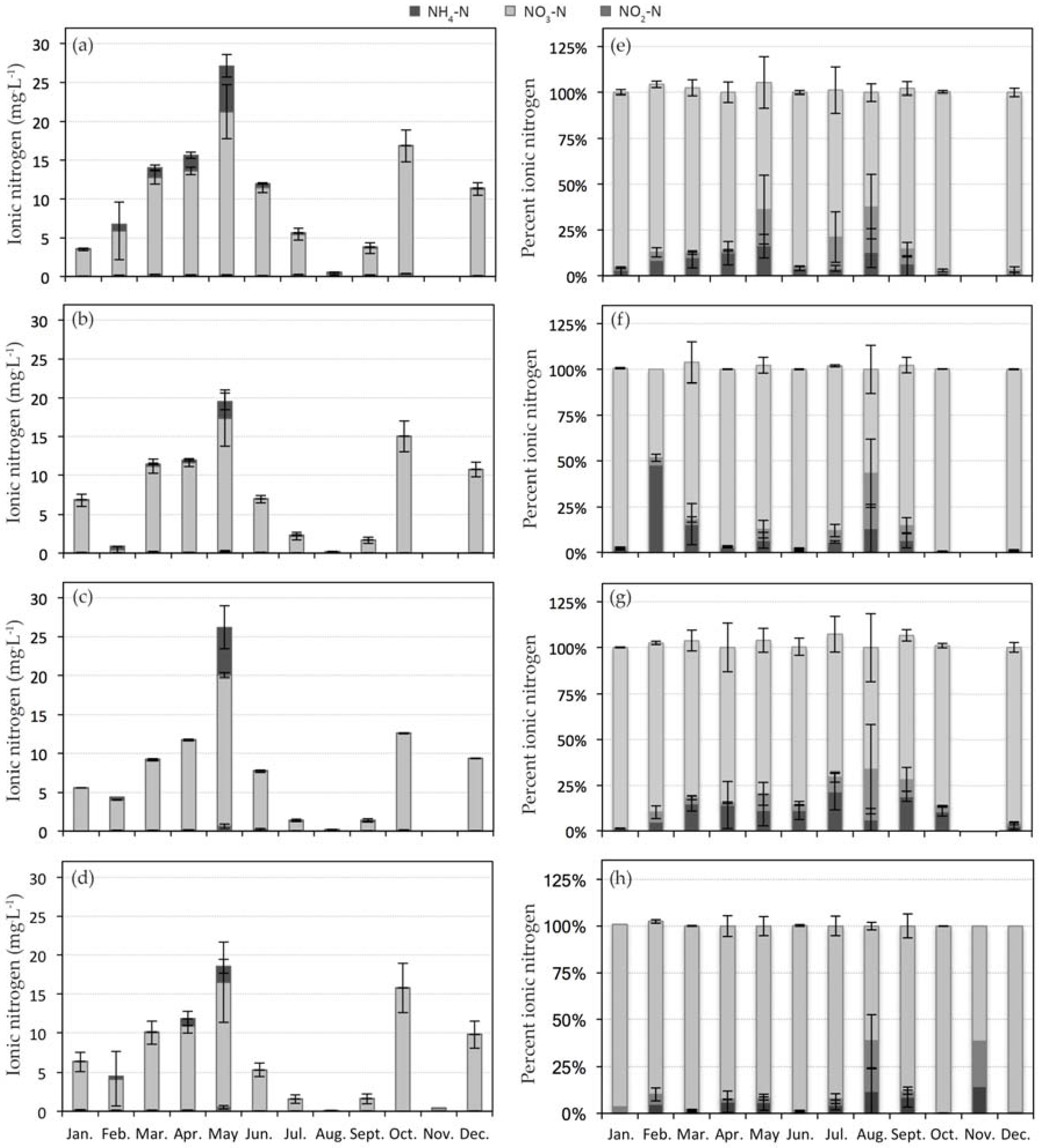
Ammonium and nitrate were the dominant forms of nitrogen in the waters flowing through Sites 1.1, 1.2 and 1.3 into Site 2 (Figure 6, Table 2). Nitrate concentrations averaged 18.9 ± 2.8 mg·L−1 in Site 1.1, 10.3 ± 1.4 mg·L−1 in Site 1.2, and 10.6 ± 2.4 mg·L−1 in Site 1.3. Seasonal peaks in ionN concentration entering the wetland were evident, with higher nutrient concentrations detected in Site 1.1 from March to June (p < 0.001). Peak nutrient concentrations during these months correlated with peaks in the plant production cycle, when supplemental fertilization occurred to support nursery crop growth. The relative proportion of nitrate, nitrite, and ammonium to ionN did not differ by site, within month or among months for water samples collected from Sites 1.1, 1.2 or 1.3.
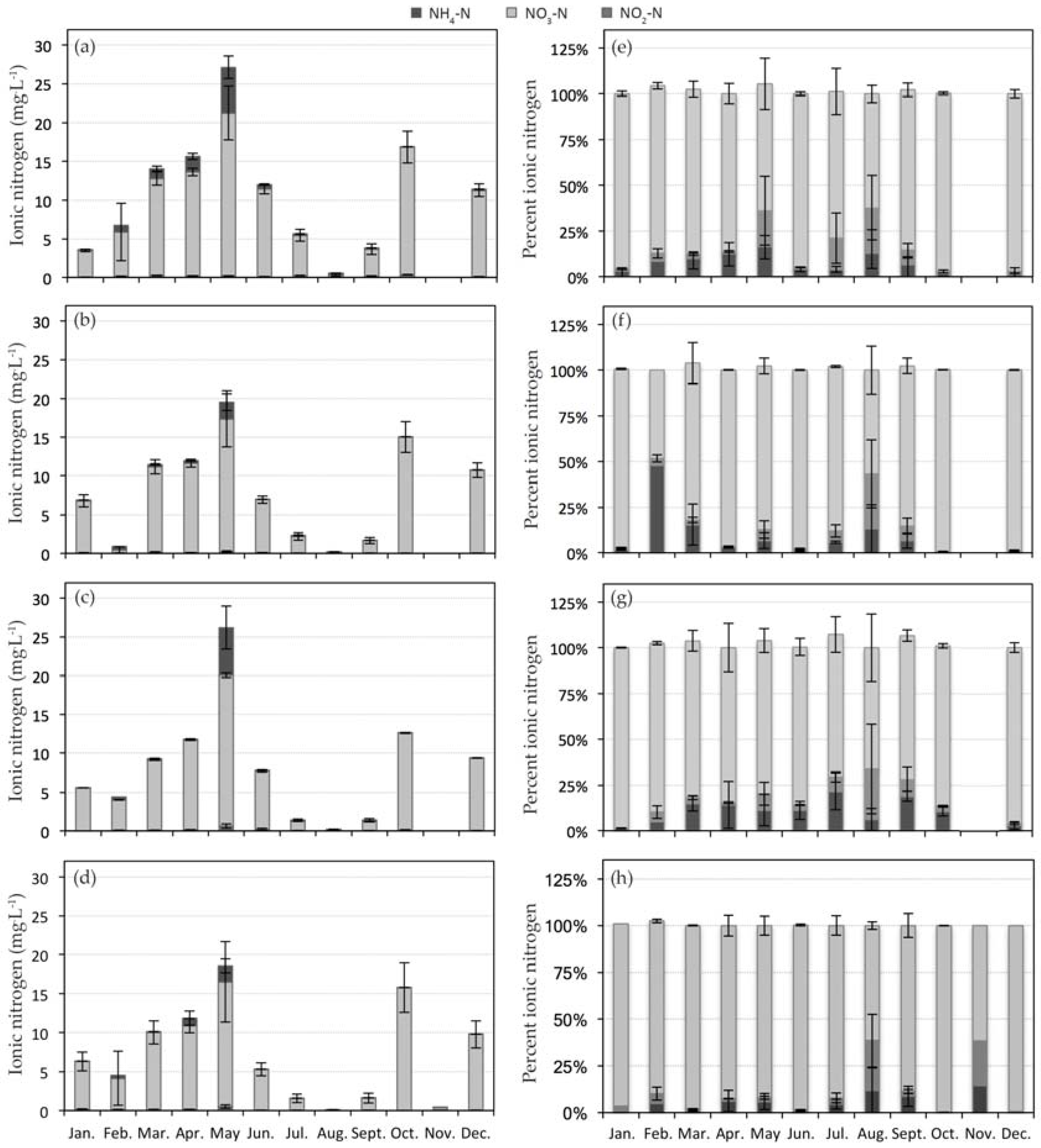
Within CW2, as production runoff flowed from Site 2 to Site 5, the concentration of ionN diminished (p = 0.002; Figure 7). Total N yearly average concentrations were 9.05 ± 1.2 mg·L−1 in Site 2, 6.84 ± 0.93 mg·L−1 in Site 3, 4.68 ± 0.67 mg·L−1 in Site 4, and 4.42 ± 0.78 mg·L−1 in Site 5. Nitrate was the dominant form of nitrogen within waters in CW2. However, the percent of ionN detected as nitrate decreased from 81.1% (Site 1) to 65.5 ± 2.3% in Sites 2 to 5. The percent of ionN measured as ammonium increased from 10.5% (Site 1) to 27.1 ± 2.3% NH3-N in Sites 2–5. The percent of ionN detected as nitrite in Sites 2–5 was 8.59 ± 0.75% and was similar to that detected in Site 1 (8.74%).
In April, the concentration of ionN in waters flowing into CW2 peaked (Figure 6). The ionN concentration of water exiting Site 2 in April (21.1 ± 2.9 mg·L−1) was reduced more than 60% from waters entering Site 1.1 (58.0 ± 20 mg·L−1) and more than 27% from waters entering Sites 1.2 and 1.3 (29.2 ± 6.2 mg·L−1) for the same period. Constructed Wetland 2 functioned efficiently from 2009 to 2013, additional detention time was not needed to attain nitrogen removal endpoints at or lower than the 10 mg·L−1 NO3-N desired US EPA drinking water quality standard [32].
Within CW2, as production runoff flowed from Site 2 to Site 5, DO and ORP were dynamic (Figure 4). In general, DO concentrations differed among sites (p < 0.003) and were lowest in Site 2 (2.7 ± 0.55 mg·L−1) and Site 4 (3.0 ± 0.47 mg·L−1), with an incremental increase in DO within Site 3 (4.2 ± 0.83 mg·L−1) and substantial increase in DO within Site 5 (5.9 ± 0.74 mg·L−1). Constructed Wetland 2 was designed to have three cells (Sites 2, 3, and 4) of lower dissolved oxygen to facilitate removal of ionN, with the final settling pond (Site 5) designed to increase dissolved oxygen concentrations in waters leaving CW2.
Oxidation reduction potential dynamics differed among sites and months within CW2 (p = 0.0008). Within CW2, ORP was more positive during cooler months (November to April). During cool months, ORP dynamics within sites were similar with a negative trend as water flowed from Site 2 to Site 5, meaning that ORP measurements were higher in Site 2 (113 ± 16.3 mV) and diminished in a linear manner to those recorded in Site 5 (62.3 ± 17.7 mV). From May to October, conditions in CW2 were consistently reducing, with ORP values consistently <0 mV, indicating dominant electron donor had changed from oxygen and nitrate to iron or sulfate.
Nitrogen removal efficacy in CW2 averaged 48.0 ± 3.2% in Site 2, 63.4 ± 2.8% in Site 3, 74.4 ± 2.4% in Site 4, and 71.8 ± 2.8% in Site 5. From November to February, ionN concentrations in water flowing into CW1 were minimal, as no supplemental fertilizer was applied to nursery crops; nutrients entering CW2 were likely those leached from containers during irrigation or storm events. Nitrogen removal efficacy in CW2 was consistently positive and ranged from 32% in December to 83% in July (Figure 5). Total N concentration measured within sites in CW2 correlated strongly with ionN removed (p < 0.0001), with similar negative trends between nitrogen concentration and percent nitrogen removed by month (p < 0.0001) and site (p < 0.0001).

4. Discussion

Biological systems are variable in nature. The variability in remediation efficacy within sites and months reflects differences in N removal dynamics among years, as at some points remediation efficacy was poor (−163%) where for the same month in an alternate year at the same site N removal efficacy was excellent (100%). Constructed wetland design was a dominant driver of ionN and N speciation within production runoff as water moved through CW1 or CW2. Within CW1, Site 1.1 (the runoff ditch channeling water from production areas into the retention pond) was designed to promote nitrification via use of aeration steps, and Sites 2 and 3 provided both deep and shallow zones, which facilitated formation of aerobic and anaerobic zones within CW1. Nitrification or biological oxidation of ammonium to nitrate is a bacteria-mediated process that requires aerobic conditions for oxidation of ammonium to nitrite and nitrite to nitrate [24]. Transformation of NH4+-N to NO3-N was a design endpoint for those managing CW1, as the slow release fertilizers applied to the nursery container crops in the production watershed contained approximately equal percentages of nitrate (45%) and ammonium (45%) and urea nitrogen (10%). Transformation of NH4+-N to NO3-N was not the design goal for CW2, rather maximizing ionN treatment capacity while minimizing CW footprint was the focus.
In CW1, the majority of ionN remediation efficacy occurred within Site 2, within a 3.5-day HRT. Taylor et al. [26] and White et al. [25] monitored CW1 from 2002 to 2006 in linked studies and reported ionN remediation efficacies ranging 60–99% in Site 2. Because of the ionN remediation efficacies of CW1 at Site 2, CW2 was designed as three sequential, deep cells to both create a similar HRT with minimal CW footprint and to encourage denitrification. Each site (Sites 2–4) in CW2 represents one additional day of HRT (three days total HRT at maximum flow capacity). When comparing remediation efficacy between CW1 (3.5-day HRT at Site 2) and CW2 (three-day cumulative HRT at Site 4), ionN remediation efficacy was higher at CW2 Site 4 (74.4 ± 2.4%) than in CW1 Site 2 (56.9 ± 2.3%), despite the shorter HRT. The higher remediation efficacies within CW2 compared with CW1 may potentially be explained by two factors: (1) nutrient concentrations were higher entering CW1; and (2) flow rates were not measured during this experiment, thus the hydraulic loading rate into CW2 may not have been at design capacity, so HRT could have been considerably longer. Interestingly, Kadlec [28] reported no enhanced processing of N when deep zones were incorporated within research wetlands in Arizona; each CW, regardless of presence or absence of a deep zone averaged 50% or greater ionN removal efficacy. While it is not possible to definitively state that ionN remediation was enhanced in deep cells within this study, the majority of ionN remediation occurred in the deep cells of both CW1 and CW2. At minimum deep cells did not inhibit denitrification processes within CW1 or CW2. The economic benefits of designing free water surface CWs with deep cells is compelling for agricultural users, as by increasing cell depth, one can increase retention time and decrease CW footprint, thereby decreasing land devoted to remediation purposes.
The greatest limitation of this study is that no flow data were available. Verification of hydraulic loading rate was not possible. Historical data regarding hydraulic loading rates into CW1 were available (Section 2.1.3) and help to answer questions regarding water volume flowing into CW1 by month. These data were not available for CW2; thus, it is not possible to parse whether high nutrient remediation efficacy values correlated with high or low hydraulic loading rates. Any fluctuations in remediation efficacy are only attributable to base design parameters. Further, because only non-flow weighted concentration data were available, extrapolations with regard to diminution of N loads into surface waters are not possible.
The ORP dynamics of CW1 and CW2 were similar over the four years of monitoring, although conditions became more reducing in CW2 from June to September, in comparison with CW1. This could partially be due to wetland design, as CW2 was designed with deep cells that promote formation of reducing conditions, and to differences in the concentrations of ionN flowing into each wetland. The 48.6 ha of production producing runoff that enters CW1 were established with larger plant materials (20 to 60 L of substrate held within a container, or containers sizes #5 to #15), that required supplemental fertilization during the summer and resided in the production area for more than one season. Irrigation runoff from 87.7 ha of production flowed into CW2; this watershed was established with smaller plant material (<19 L of substrate held within a container, or container sizes #1 to #5) that were fertilized with a controlled release fertilizer (slow release fertilizer), required no supplemental fertilization, and sold from the site within one year. These differences in plant species grown, container sizes and fertilization strategies led to differences in concentration of ionN in waters flowing into the CW1 and CW2.
While CW1 is nearly 20 years older than CW2, it was also subjected to higher nutrient concentrations consistently across seasons and years than was CW2. Vegetation richness in CW1 was much greater than that within CW2. Vegetation within CW2 was dominated by two plant species, Pontederia cordata and Hydrocotyle umbellata, while vegetation within CW1 was diversified through 24 plant species [31]. Vymazal [33] reported that treatment performance of a CW could be influenced by the plants species used. Bachand [34] reported that a mixture of floating and emergent species was recommended for improving denitrification rates. Thus, it is possible that plant species differences between CW1 and CW2 affected ionN remediation efficacy; as CW2 vegetation was dominated by a floating and emergent plant species, while CW1 vegetation is dominated by a diversity of emergent plant species. In CW1, no open water zones existed either within Site 2 or Site 3. Within CW2, open water zones existed within Sites 3 and 4; open water zones may have contributed to increased dissolved oxygen, as increased mixing aided by wind likely occurred. In CW1, remediation performance was adequate to meet drinking water quality standards in all months save during May; CW2 met these standards regardless of season. Similar trends in seasonality of performance in free water surface wetlands were reported by some researchers [25,26], while other reported no difference in free water surface wetland ionN removal over different seasons [35].
Differences in ionN removal efficacies and shifts in N species dominance in CW1 and CW2 were controlled by constructed wetland design (depth and HRT), ionN concentration and plant species richness. The contributions of HRT to N remediation are well-defined. The influence of CW depth, plant species richness, and microbial community dynamics merit additional study and characterization. Each application of CW is constrained by site-specific characteristics. Developing data resources rich in parameters beyond contaminant concentration and hydraulic loading are needed. Microbial community diversity and dynamics, as influenced by CW age, seasonality, and plant richness, are likely highly pertinent factors regulating remediation efficacy, yet they are poorly understood and defined within most CWs.
Trends over time in the functionality of biological treatment systems like CWs should be used as gauges of success rather than singular points in time, as single points in time may over- or under-predict the efficacy of the treatment systems. Wastewater source and composition are critical factors influencing system performance, along with environmental factors (temperature and rainfall) which are beyond system designer control. Remediation of water sources with higher nutrient concentrations may require longer retention times or a larger CW footprint to consistently meet nutrient removal goals. Depending upon the purpose (user) of the CW, the design could be based on typical concentration and flow rates, or for contaminant mitigation during extreme events. Design considerations need to take into account economic, environmental, and grower logistics for successful and continued adoption of constructed wetlands for wastewater treatment.

5. Conclusions

Constructed wetland maturity plays a role in remediation efficacy. Constructed Wetland 1 was constructed 11 years before CW2. Plant species richness varied dramatically within the 2 CWs, with more than 141 plant species catalogued in CW1 and less than 10 plant species catalogued within CW2. Nitrate-N was the dominant form of ionN present in both CWs. Within CW1, a deep cell to shallow cell design, NO3-N comprised ~86% of ionN in effluent. Within CW2, designed with three sequential deep cells, NO3-N comprised only ~66% of ionN, while NH4+-N comprised nearly 27% of ionN in CW2 effluent. This shift in ionN speciation is reflective of the redox conditions within the cell and the dominant microbial processes regulating N remediation. Both redox conditions and microbial community density and composition are direct reflections of constructed wetland design (depth and hydraulic retention time), the concentration of nutrients entering the CW, and plant species richness. All of these factors influence contaminant fate within constructed wetland systems.

Acknowledgments

This material is based upon work that is supported by the National Institute of Food and Agriculture (NIFA), U.S. Department of Agriculture (USDA), under award number 2014-51181-22372 and NIFA USDA/Agriculture Resource Service, Floriculture and Nursery Research Initiative specific cooperative agreement #58-6618-2-0209. Technical Contribution No. 6612 of the Clemson University Experiment Station, linked to Experiment Station project 1700536.

Conflicts of Interest

The author declares no conflict of interest. The funding sponsors had no role in the design of the study; in the collection, analyses, or interpretation of data; in the writing of the article, and in the decision to publish the results.

References

  1. Headley, T.R.; Dirou, J.; Huett, D.; Stovold, G.; Davison, L. Reed beds for the remediation and recycling of nursery runoff water. Australas. J. Environ. Manag. 2005, 12, 27–36. [Google Scholar] [CrossRef]
  2. White, S.A. Wetland technologies for nursery and greenhouse compliance with nutrient regulations. HortScience 2013, 48, 1103–1108. [Google Scholar]
  3. Majsztrik, J.C.; Fernandez, R.T.; Fisher, P.R.; Hitchcock, D.R.; Lea-Cox, J.; Owen, J.S., Jr.; Oki, L.R.; White, S.A. Water use and treatment in container-grown specialty crop production: A review. Water Air Soil Pollut. 2017, 228, 151. [Google Scholar] [CrossRef] [PubMed]
  4. Sample, D.J.; Grizzard, T.J.; Sansalone, J.; Davis, A.P.; Roseen, R.M.; Walker, J. Assessing performance of manufactured treatment devices for the removal of phosphorus from urban stormwater. J. Environ. Manag. 2012, 113, 279–291. [Google Scholar] [CrossRef] [PubMed]
  5. Scholes, L.; Revitt, D.M.; Ellis, J.B. A systematic approach for the comparative assessment of stormwater pollutant removal potentials. J. Environ. Manag. 2008, 88, 467–478. [Google Scholar] [CrossRef] [PubMed]
  6. Somes, N.L.G.; Fabian, J.; Wong, T.H.F. Tracking pollutant detention in constructed stormwater wetlands. Urban Water 2000, 2, 29–37. [Google Scholar] [CrossRef]
  7. Wittgren, H.B.; Tobiason, S. Nitrogen removal from pretreated wastewater in surface flow wetlands. Water Sci. Technol. 1995, 32, 69–78. [Google Scholar]
  8. Billmayer, J.J. Wastewater Technology Fact Sheet, Free Water Surface Wetlands; United States Environmental Protection Agency: Washington, DC, USA, 2000; pp. 1–8.
  9. García-Lledó, A.; Ruiz-Rueda, O.; Vilar-Sanz, A.; Sala, L.; Bañeras, L. Nitrogen removal efficiencies in a free water surface constructed wetland in relation to plant coverage. Ecol. Eng. 2011, 37, 678–684. [Google Scholar] [CrossRef]
  10. Calheiros, C.S.C.; Rangel, A.O.S.S.; Castro, P.M.L. Constructed wetland systems vegetated with different plants applied to the treatment of tannery wastewater. Water Res. 2007, 41, 1790–1798. [Google Scholar] [CrossRef] [PubMed]
  11. Vymazal, J. Constructed wetlands for water quality regulation. In The Wetland Book; Springer: Dordrecht, The Netherlands, 2016; pp. 1–8. [Google Scholar]
  12. Arheimer, B.; Wittgren, H.B. Modelling nitrogen removal in potential wetlands at the catchment scale. Ecol. Eng. 2002, 19, 63–80. [Google Scholar] [CrossRef]
  13. Kadlec, R.H.; Wallace, S.D. Treatment Wetlands, 2nd ed.; CRC Press: Boca Raton, FL, USA, 2009; p. 366. [Google Scholar]
  14. White, S.A.; Cousins, M.M. Floating treatment wetland aided remediation of nitrogen and phosphorus from simulated stormwater runoff. Ecol. Eng. 2013, 61, 207–215. [Google Scholar] [CrossRef]
  15. Kadlec, R.H.; Tanner, C.C.; Hally, V.M.; Gibbs, M.M. Nitrogen spiraling in subsurface-flow constructed wetlands: Implications for treatment response. Ecol. Eng. 2005, 25, 365–381. [Google Scholar] [CrossRef]
  16. Ahn, C.; Mitsch, W.J. Scaling considerations of mesocosm wetlands in simulating large created freshwater marshes. Ecol. Eng. 2002, 18, 327–342. [Google Scholar] [CrossRef]
  17. White, S.A.; Taylor, M.D.; Albano, J.P.; Whitwell, T.; Klaine, S.J. Phosphorus retention in lab and field-scale subsurface-flow wetlands treating plant nursery runoff. Ecol. Eng. 2011, 37, 1968–1976. [Google Scholar] [CrossRef]
  18. Hernandez, M.E.; Mitsch, W.J. Denitrification potential and organic matter as affected by vegetation community, wetland age, and plant introduction in created wetlands. J. Environ. Qual. 2007, 36, 333–342. [Google Scholar] [CrossRef] [PubMed]
  19. Bachand, P.A.M.; Horne, A.J. Denitrification in constructed free-water surface wetlands: I. Very high nitrate removal rates in a macrocosm study. Ecol. Eng. 2000, 14, 9–15. [Google Scholar] [CrossRef]
  20. Maine, M.A.; Hadad, H.R.; Sánchez, G.C.; Di Luca, G.A.; Mufarrege, M.M.; Caffaratti, S.E.; Pedro, M.C. Long-term performance of two free-water surface wetlands for metallurgical effluent treatment. Ecol. Eng. 2017, 98, 372–377. [Google Scholar] [CrossRef]
  21. Wu, S.; Kuschk, P.; Brix, H.; Vymazal, J.; Dong, R. Development of constructed wetlands in performance intensifications for wastewater treatment: A nitrogen and organic matter targeted review. Water Res. 2014, 57, 40–55. [Google Scholar] [CrossRef] [PubMed]
  22. Lee, C.-G.; Fletcher, T.D.; Sun, G. Nitrogen removal in constructed wetland systems. Eng. Life Sci. 2009, 9, 11–22. [Google Scholar] [CrossRef]
  23. Charpentier, J.; Florentz, M.; David, G. Oxidation-reduction potential (orp) regulation: A way to optimize pollution removal and energy savings in the low load activated sludge process. Water Sci. Technol. 1987, 19, 645–655. [Google Scholar]
  24. Vymazal, J. Removal of nutrients in various types of constructed wetlands. Sci. Total Environ. 2007, 380, 48–65. [Google Scholar] [CrossRef] [PubMed]
  25. White, S.A.; Taylor, M.D.; Chandler, S.L.; Whitwell, T.; Klaine, S.J. Remediation of nitrogen and phosphorus from nursery runoff during the spring via free water surface constructed wetlands. J. Environ. Hortic. 2010, 28, 209–217. [Google Scholar]
  26. Taylor, M.D.; White, S.A.; Chandler, S.L.; Klaine, S.J.; Whitwell, T. Nutrient management of nursery runoff water using constructed wetland systems. HortTechnology 2006, 16, 610–614. [Google Scholar]
  27. Prenafeta-Boldú, F.X.; Trillas, I.; Vinas, M.; Guivernau, M.; Cáceres, R.; Marfa, O. Effectiveness of a full-scale horizontal slow sand filter for controlling phytopathogens in recirculating hydroponics: From microbial isolation to full microbiome assessment. Sci. Total Environ. 2017, 599–600, 780–788. [Google Scholar] [CrossRef] [PubMed]
  28. Kadlec, R.H. The effects of deep zones on wetland nitrogen processing. Water Sci. Technol. 2007, 56, 101–108. [Google Scholar] [CrossRef] [PubMed]
  29. Weller, M.W. Management of freshwater marshes for wildlife. In Freshwater Wetlands: Ecological Processes and Management Potential; Good, R.E., Whingham, D.F., Simpson, R.L., Eds.; Academic Press: New York, NY, USA, 1978; pp. 267–284. [Google Scholar]
  30. Land, M.; Granéli, W.; Grimvall, A.; Hoffmann, C.C.; Mitsch, W.J.; Tonderski, K.S.; Verhoeven, J.T.A. How effective are created or restored freshwater wetlands for nitrogen and phosphorus removal? A systematic review. Environ. Evid. 2016, 5. [Google Scholar] [CrossRef]
  31. White, S.A.; Taylor, M.D.; Damrel, D.Z. Floral colonization of a free-water surface constructed wetland System in Grady County, Georgia. Castanea 2012, 77, 159–171. [Google Scholar] [CrossRef]
  32. USEPA. National Primary Drinking Water Regulations; Office of Ground Water and Drinking Water: Washington, DC, USA, 2009.
  33. Vymazal, J. Emergent plants used in free water surface constructed wetlands: A review. Ecol. Eng. 2013, 61, 582–592. [Google Scholar] [CrossRef]
  34. Bachand, P.A.M.; Horne, A.J. Denitrification in constructed free-water surface wetlands: II. Effects of vegetation and temperature. Ecol. Eng. 2000, 14, 17–32. [Google Scholar] [CrossRef]
  35. Hsueh, M.-L.; Yang, L.; Hsieh, L.-Y.; Lin, H.-J. Nitrogen removal along the treatment cells of a free-water surface constructed wetland in subtropical taiwan. Ecol. Eng. 2014, 73, 579–587. [Google Scholar] [CrossRef]
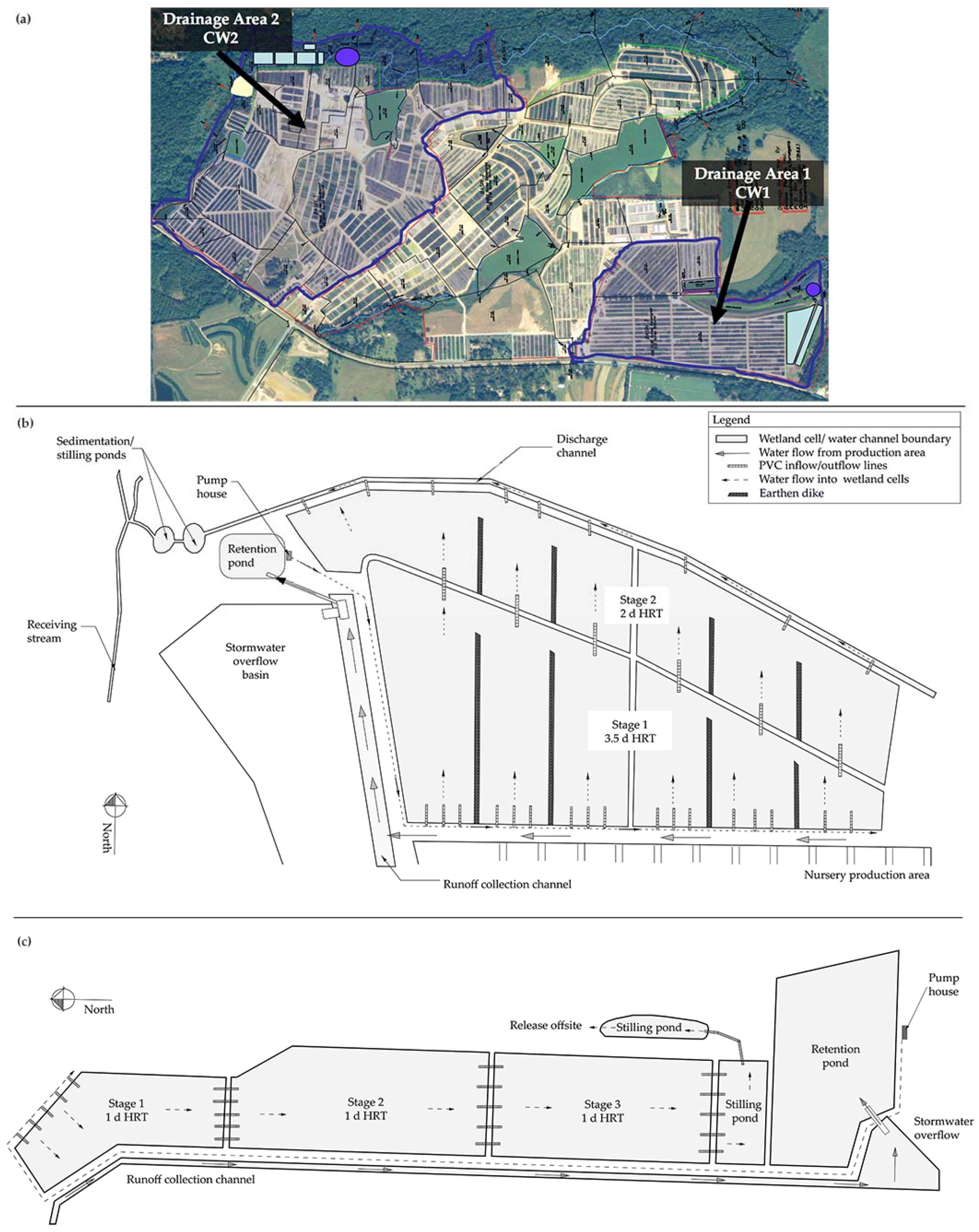
Figure 1. The two constructed wetlands monitored are southwest of the city of Cairo, GA, USA and treat runoff in the drainage areas (a) highlighted/bounded in dark blue at the ornamental plant nursery. Constructed Wetland 1 (b) receives irrigation runoff from drainage area 1. Constructed Wetland 2 (c) receives irrigation runoff from drainage area 2.
Water 10 00008 g001
Figure 2. The concentration and percent of ionic nitrogen (nitrite (NO2-N), nitrate (NO3-N) and ammonium (NH4+-N)) detected within sites in Constructed Wetland 1 (CW1): (a,d) Site 1.1 (inflow ditch/runoff channel); (b,e) Site 1.2 (retention pond); and (c,f) Site 1.3 (direct inflow to Stage 1 of CW1). Error bars represent the standard error (±) of the mean value.
Water 10 00008 g002
Figure 3. The concentration and percent of ionic nitrogen (nitrite (NO2-N), nitrate (NO3-N) and ammonium (NH4+-N)) detected in sites within Constructed Wetland 1: (a,e) Site 2 (outflow from Stage 1); (b,f) Site 3 (outflow from Stage 2); (c,g) Site 4 (discharge channel); and (d,h) Site 5 (stilling ponds). Error bars represent the standard error (±) of the mean value.
Water 10 00008 g003
Figure 4. Monthly average dissolved oxygen (DO mg·L−1) and oxidation reduction potential (ORP, mVolt) measured within Sites 2 to 5 in: Constructed Wetland 1 (CW1) (a,b); and Constructed Wetland 2 (CW2) (c,d). Sites within CW1 include outflow from Stage 1 (Site 2), outflow from Stage 2 (Site 3), runoff ditch with effluent exiting Stage 2 (Site 4), and the stilling pond (Site 5). Sites within CW2 include outflow from Stage 1 (Site 2), outflow from Stage 2 (Site 3), outflow from Stage 3 (Site 4), and the stilling pond (Site 5). Error bars represent the standard error (±) of the mean value.
Water 10 00008 g004
Figure 5. Average ionic nitrogen removal efficacy in: Constructed Wetland 1 (a); and Constructed Wetland 2 (b). Sites within Constructed Wetland 1 include outflow from Stage 1 (Site 2), outflow from Stage 2 (Site 3), runoff ditch with effluent exiting Stage 2 (Site 4), and the stilling pond (Site 5). Sites within Constructed Wetland 2 include outflow from Stage 1 (Site 2), outflow from Stage 2 (Site 3), outflow from Stage 3 (Site 4), and the stilling pond (Site 5). Error bars represent the standard error (±) of the mean value.
Water 10 00008 g005
Figure 6. The concentration and percent of ionic nitrogen [nitrite (NO2-N), nitrate (NO3-N) and ammonium (NH4+-N)] detected within Sites 1.1, 1.2, and 1.3 in Constructed Wetland 2 (CW2): (a,d) Site 1.1 (inflow ditch/runoff channel); (b,e) Site 1.2 (retention pond); and (c,f) Site 1.2 (direct inflow to Stage 1 of CW2). Error bars represent the standard error (±) of the mean value.
Water 10 00008 g006
Figure 7. The concentration and percent of ionic nitrogen [nitrite (NO2-N), nitrate (NO3-N) and ammonium (NH4+-N)] detected in sites within Constructed Wetland 2 (CW2): (a,e) Site 2 (outflow from Stage 1); (b,f) Site 3 (outflow from Stage 2); (c,g) Site 4 (outflow from Stage 3); and (d,h) Site 5 (stilling pond). Error bars represent the standard error (±) of the mean value.
Water 10 00008 g007
Table 1. Key to site descriptions within constructed wetland (CW) 1 and 2, and number of sub-sampling sites from which water was collected and mixed for composite samples.
Site KeyCW1Composite Sub-SitesCW2Composite Sub-Sites
1.1Inflow ditch/runoff channel4Inflow ditch/runoff channel2
1.2Retention pond1Retention pond1
1.3Inflow to CW15Inflow to CW23
2Outflow Stage 16Outflow Stage 13
3Outflow Stage 26Outflow Stage 23
4Discharge channel3Outflow Stage 33
5Stilling ponds3Stilling ponds2
Table 2. Annual average (± standard error) concentration and percent of total ionic N (nitrate (NO3-N), nitrite (NO2-N) and ammonium (NH3-N)) in two constructed wetland (CW) by sampling site.
SiteConcentration of Ionic NitrogenPercent of Ionic Nitrogen
NO3-N (mg/L)NO2-N (mg/L)NH3-N (mg/L)ionicN (mg/L)% NO3-N% NO2-N% NH3-N
CW11.124.7 ± 1.581.06 ± 0.067.97 ± 1.0632.7 ± 2.4778.6 ± 1.45.4 ± 1.116.7 ± 1.3
1.214.0 ± 1.701.05 ± 0.134.05 ± 0.9818.1 ± 2.4577.4 ± 3.010.9 ± 3.012.1 ± 2.2
1.316.1 ± 0.841.39 ± 0.073.51 ± 0.4020.6 ± 1.2077.5 ± 1.29.2 ± 1.013.7 ± 1.1
210.1 ± 0.710.18 ± 0.111.15 ± 0.2311.3 ± 0.8886.4 ± 1.65.6 ± 1.18.3 ± 1.2
38.07 ± 0.670.09 ± 0.010.35 ± 0.138.47 ± 0.7588.8 ± 1.75.1 ± 1.16.3 ± 1.3
47.73 ± 1.180.16 ± 0.050.80 ± 0.418.56 ± 1.5087.6 ± 2.55.2 ± 1.57.5 ± 2.2
57.52 ± 0.960.12 ± 0.030.36 ± 0.157.94 ± 1.0688.9 ± 2.26.5 ± 1.64.8 ± 1.2
CW21.118.9 ± 2.840.81 ± 0.116.49 ± 1.7325.0 ± 4.1482.3 ± 2.86.7 ± 2.011.5 ± 2.4
1.210.3 ± 1.360.82 ± 0.132.50 ± 0.6313.3 ± 1.9780.4 ± 2.49.5 ± 2.110.5 ± 1.5
1.310.6 ± 2.380.82 ± 0.161.46 ± 0.4812.5 ± 2.6580.4 ± 3.310.8 ± 3.29.1 ± 1.7
27.28 ± 0.950.66 ± 0.091.32 ± 0.229.05 ± 1.1869.8 ± 3.79.2 ± 1.422.1 ± 3.5
35.73 ± 0.780.48 ± 0.090.84 ± 0.136.84 ± 0.9464.2 ± 4.67.9 ± 1.229.2 ± 4.7
43.94 ± 0.590.37 ± 0.080.52 ± 0.064.68 ± 0.6762.1 ± 5.69.2 ± 1.730.1 ± 4.8
53.92 ± 0.720.30 ± 0.090.38 ± 0.054.43 ± 0.7866.6 ± 5.57.8 ± 1.826.9 ± 5.9