Abstract
The two-dimensional video distrometer (2DVD) is a well known ground based point-monitoring precipitation gauge, often used as a ground truth instrument to validate radar or satellite rainfall retrieval algorithms. This instrument records a number of variables for each detected hydrometeor, including the detected position within the sample area of the instrument. Careful analyses of real 2DVD data reveal an artifact—there are time periods where hydrometeor detections within parts of the sample area are artificially enhanced or diminished. Here, we (i) illustrate this anomaly with an exemplary 2DVD data set, (ii) describe the origin of this anomaly, (iii) develop and present an algorithm to help flag data potentially partially corrupted by this anomaly, and (iv) explore the prevalence and quantitative impact of this anomaly. Although the anomaly is seen in every major rain event studied and by every 2DVD the authors have examined, the anomaly artificially induces less than 3% of all detected drops and typically alters estimates of rain rates and accumulations by less than 2%.
1. Introduction
The two-dimensional video disdrometer (hereafter 2DVD) (Joanneum Research, Graz, Austria) is an optical system designed to identify and measure individual rain drops falling through a sensing area of approximately 100 cm. This instrument, initially developed in the early 1990s, has been continuously improved and now serves as an important tool in a wide variety of studies related to rain characterization and ground validation [1,2,3,4,5,6,7,8,9,10,11,12,13,14,15,16,17,18,19,20,21,22,23,24,25,26,27,28,29]. Although many of the instrument’s limitations are well known (e.g., [8,30,31,32,33,34]), the 2DVD is generally considered quite reliable—it is still being used today as a tool for ground validation and/or as a reference for comparison to other rain measurement instruments (see, e.g., [16,20,24]).
Here, we identify an anomaly in 2DVD data that—to our knowledge—has not been previously reported. There is clear evidence in our data that about 15% of all detected drops are observed during times when parts of the instrumental field-of-view are supplying spurious data. This anomaly occurs in all 2DVDs and all rain events examined. Fortunately, the fraction of the field of view that is affected by this anomaly is typically small, and the anomaly most commonly induces spurious detections of very small drops that do not substantially affect the measured rain accumulations. Ultimately, we find the total effect of this anomaly to induce a slight overestimation of no more than about 1–2% above the detected accumulations in an absence of the anomaly.
Because of the wide use of 2DVD, careful quantification of this anomaly is important. Measurement uncertainties related to instrument intercomparison (see, e.g., [2,3,7,13,14,20,26,35,36,37]) still far exceed the magnitude of the anomaly on rainfall estimation, and it is not expected that the effect seen in this anomaly will substantially weaken the results of any previous study we are aware of.
The rest of this paper outlines the basic design of the 2DVD, shows an example anomaly, explains the physical origin of the anomaly, and then characterizes and quantifies the anomalous data.
2. Materials and Methods
The 2DVD (Joanneum Research) has been aptly described and characterized previously (see, e.g., [8,30,31,32,33,34]), so only the basics are re-introduced here.
Two high speed line scan cameras look into a brightly illuminated background, with any hydrometeors detected as shadows. The two cameras are aligned orthogonally to each other, with a height difference of approximately 6–7 mm. This allows the recording of images from front and side views and measurement of the fall velocity of hydrometeors. The intersecting part of the two cameras’ field of views define the measuring area, its size being around 10 cm by 10 cm. Data from each hydrometeor are stored with a precise time stamp.
This measurement principle reveals many advantages for the data analysis, with some of the most important ones being:
- The individually recorded hydrometeors allow the investigator to freely choose integration time intervals in post processing for rain rates and for drop size distributions.
- The measuring area is defined by the intersection of two optical paths and not by the rim of the housing, making the effect of splashing negligible.
- The large measurement area allows recording of hydrometeors of any size.
- The orthogonally aligned cameras provide the location within the measuring area where each hydrometeor arrives. This allows for investigation of sub-sections of the measuring area and exploration of the statistical significance of results. (For the present study, this information is of fundamental importance.)
- Reliable estimates of each hydrometeor’s horizontal velocity can be derived from the line scan recordings.
- The fall velocity of each hydrometeor is measured, which supplies a valid basis for the conversion from area-related measurements to volume-related drop size distributions. This velocity measurement also serves as a reliable indicator for hydrometeor phase (rain drop, snowflake, hailstone, etc.).
The structure and design of the 2DVD follows the guidelines of the WMO [38] as much as possible.
To date, more than 100 units have been delivered and are used in various parts of the world. Since 2DVD development began in 1991, three versions have been released: the Classic Tall 2DVD, the Low-Profile 2DVD and the Compact 2DVD. All analyses that follow in this manuscript are derived from data gathered by Compact 2DVDs.
3. Results
Typically, data from 2DVDs are used to measure/infer rain rate, rain accumulations, and particle size distributions. Previous studies with the 2DVD have often explored how measurements of these three variables compare to co-located instruments using different measurement principles. As such, these studies have been able to establish the reliability of 2DVD data by direct comparison to other devices. Of course, there is also the question as to the reliability of the instrument the 2DVD is being compared to.
Here, no comparison to other detectors is attempted or necessary; the anomaly that will be identified clearly affects only part of the instrumental field-of-view and, thus, an absolute assessment of the impact of the anomaly is possible.
3.1. Demonstration of the Anomaly
Although the 2DVD sample volume really can best be mapped as the intersection of two horizontal trapezoidal areas (see Figure 3 of [31], Figure 3 of [30], and/or Figure 4 of [33]), most studies have approximated this sample area as a square approximately 10 cm on a side [31]. For simplicity in visualization, we utilize this same approximation.
A display of approximate drop detection positions within this sample area can be made by taking the midpoint between the minimum and maximum pixel number covered by the drop along each camera’s field of view.
Figure 1 shows two “heat-maps” (two-dimensional histograms) of particle detection positions for 1000 consecutive detected raindrops in a 2DVD.
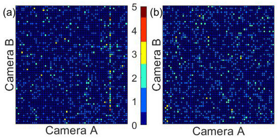
Figure 1.
A “heat-map” of the approximate two-dimensional detection positions of 1000 consecutive raindrops during a rain event detected by 2DVD (The two-dimensional video distrometer) SN074 on 2 January 2014. Each “cell” in the figure corresponds to an area corresponding to 10 pixels by 10 pixels of the measurement cameras, approximately an area of 0.024 cm. (a) a two-dimensional histogram of 1000 consecutive raindrop arrival positions during a time interval where anomalous particle detections clearly exist. The color bar in the center (used for both panels) shows the number of drops detected within each 10 pixel by 10 pixel area. (Note the clearly artificial-looking vertical line in the rightmost portion of the left panel). (b) a two-dimensional histogram of 1000 consecutive raindrop arrival positions at a different time during the same event. No artificial structures are evident, and no values above 3 are detected for any 10 pixel by 10 pixel cell.
When looking at the data in Figure 1, the anomaly is obvious; the left panel has a series of presumably spurious particle detections along a vertical line.
In addition to vertical and/or horizontal lines of artificially high particle concentrations, further analysis of 2DVD data also occasionally reveals lines of diminished particle detections (vertical or horizontal lines through the field of view where the expected number of particles has clearly been depleted). These regions are harder to visually identify in 1000 raindrop intervals but can become visible when looking at more drops at a time (see Figure 2).
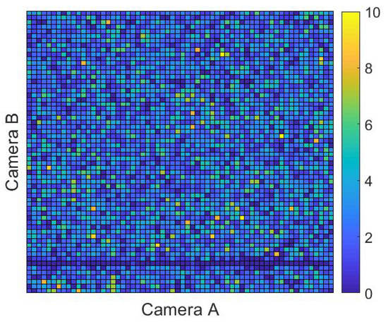
Figure 2.
Similar to Figure 1, except showing particle detection positions of 10,000 consecutive detected raindrops. Here, the lack of particles along the horizontal line near the bottom of the figure suggests some instrumental anomaly. Data shown here was drawn from 2DVD SN074 for rain that was detected on 23 May 2017.
3.2. Physical Origin of the Anomaly
As mentioned above, the 2DVD measurement principle is based on sequential images from two line scan cameras, aligned orthogonally against each other. The cameras look into a brightly illuminated background, with any particles falling between camera and illumination being detected as blockages of light. For sake of compactness of the instrument, mirrors fold the optical path between the camera and illumination unit. Cameras, the illumination units, and the mirrors are protected against precipitation by a housing. The view into the open atmosphere in each of the two optical systems is given by two narrow slits, yielding a portion of 25 cm radial length of the field of view being exposed to precipitation. The intersecting part of these portions in the two cameras create the virtual measurement area as is visualized in Figure 3. In this schematic view of the housing’s inlet, the two optical paths and their intersecting area are indicated.
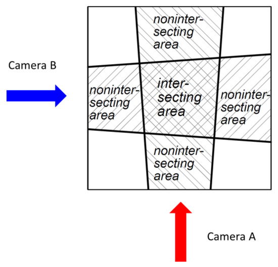
Figure 3.
Schematic view of the 2DVD’s housing inlet with the intersecting area of the two optical paths creating the 2DVD’s virtual measuring area.
In the explanation that follows, the terms object, image, and element are used as follows: ‘object’ stands for the physical precipitation particle, ‘image’ stands for the recordings of the cameras, and ‘element’ denotes the representation of a precipitation particle identified as valid in one of the two cameras’ images.
It might seem to be advantageous to close the two slits between the camera and illumination unit by protective glass. However, it is impossible that the measurement process would ignore static droplets on such glass, even with carefully chosen depth of field parameters. The field of view from the camera to the illumination unit must be open, with only the particles to be measured being allowed in between. Thus, the slits were designed to be as narrow as possible; otherwise, in conditions of heavy rain and strong winds, small droplets reach the mirrors within the housing. At the same time, the slits must be wide enough so that droplets hanging from the upper rim do not reach the camera’s field of view. Though special design structures reduce the number of drops hanging from the upper rim, the choice of the widths of the slits is a delicate compromise.
The present study reveals that either a small number of tiny droplets reach the mirrors and/or a small number of hanging drops are detected in the field of view. Both of these phenomena are seen either as a constant shadow by the relevant camera, or as a series of many consecutive elements, when, during the evaporation process, their shadow is just around the detection threshold.
3.2.1. Anomaly with Spurious Particle Detection
Figure 4 gives an illustration for the case of a static object appearing as a series of many consecutive elements. Both of the 2DVD cameras’ raw data streams are shown, in a scanning time vs. pixel count representation. This snapshot shows some 30 ms on the y-axis and the 630 pixels along the scan line in the x-axis, for the front and side views. The images of the front view camera are given in the left panel, and those of the side view camera in the right panel. The 2DVD software matches elements of the front and side view cameras, meaning it identifies elements stemming from the same particle. Since there is a height difference of between 6 and 7 mm between the two optical planes, elements from the same particle appear with a slight time difference in the data streams from the two cameras, which result in pair-matching attempts (black and yellow lines) to be slanted. In the side view, an evaporating static droplet causes a series of continuous elements; the image of the static droplet fluctuates near the detection threshold (which is why the mostly solid vertical line near 460 pixels on the right panel still has a few gaps).
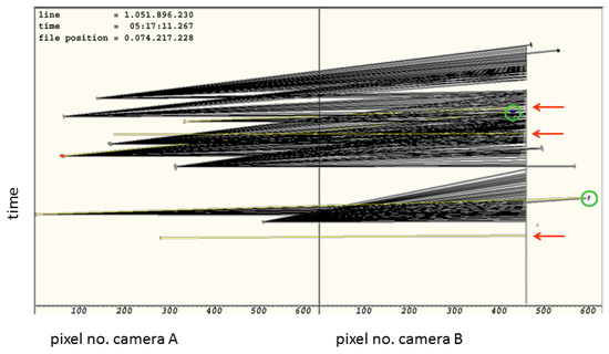
Figure 4.
Synchronous view of both cameras’ raw data streams, in a scanning time vs. pixel count (location) representation. Rain drops are visible in front (left panel) and side views (right panel). In the side view, an evaporating static droplet causes a series of continuous elements, seen as vertical line. Black lines denote declined matching attempts. Yellow lines denote matched pairs of elements, being accepted to stem from the same particle. Red arrows denote elements with false matching to the static object. Green circles denote correct matching.
Figure 4 shows that, in this ∼30 ms interval, there were ten elements seen in camera A. For each of these elements, the algorithm checks if a plausible corresponding element is seen by camera B. Black lines denote declined matching attempts, whereas yellow lines denote matched pairs of elements being accepted to stem from the same particle. It is clearly visible that, within the period shown, three elements of the front view camera are falsely matched to the static object seen by the side view camera. The first of these three falsely accepted matching pairs corresponds to the lowest yellow line. The three false matches are marked by red arrows. In addition, two truly matched pairs are seen, marked by green circles.
The herewith visualized effect of falsely matched static objects explains why spurious particles are detected. For the time period of evaporation, the location of such spurious particles happens at the same pixel count in that camera that sees the static object. Thus, in the “heat map” shown in Figure 1, the spurious particles appear as a straight line along the field of view of that camera, which sees the static object. The distance to this camera is determined by the pixel count of the other camera’s elements, which are falsely matched to the static object.
3.2.2. Anomaly with Lack of Particles
Figure 5 gives an illustration for the case of a static object appearing as a constant element. The same as in Figure 4, this snapshot shows some 30 ms on the y-axis and the 630 pixels along the scan line in the x-axis, for front and side views. Unlike in Figure 4, this figure does not have the time scale for the front and side views synchronized; the two panels show raw data recorded at slightly different times. (This visualization shows the raw data signals as they are alternatively fetched from camera A and camera B). Thus, no matching attempts are indicated since, in this asynchronous representation, the elements in the two halves generally do not stem from the same particles. Instead, the coloring in the asynchronous representation shows elements identified as valid particles’ images by either red or blue colors, and invalid elements by a gray color. The static object seen in the side view appears as a constant shadow, represented by a vertical line. This static object cannot be resolved as a valid precipitation particle and thus is denoted by a gray color. A true rain drop hitting the same pixel location cannot be resolved either. In Figure 5, this is denoted by a red arrow.
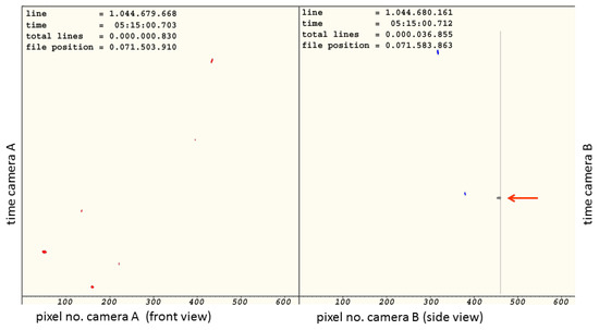
Figure 5.
Asynchronous view of both 2DVD cameras’ raw data streams, in a scanning time vs. pixel count (location) representation. The right panel shows the side view camera, with a static object appearing as a constant vertical line. A rain drop appears at the same pixel location but cannot be resolved. This missed rain drop is denoted by the red arrow.
The herewith visualized effect of rain drops not being resolved explains the lack of particles shown in Figure 2. For the time period of a constant shadow, the location of such lack of particles happens around the same pixel count in that camera, which sees the static object. Thus, in Figure 2, the lack of particles appears as a straight line along the field of view of that camera that sees the static object. The distance to this camera is determined by the pixel count of the other camera’s elements, which are ignored since their true matching partner could not be resolved.
3.3. Identifying/Flagging the Anomaly
Once the presence of the anomaly is known, it is typically easy to visually identify it in the data (for example, see Figure 1, where the vertical line is clearly evident). When analyzing a large amount of 2DVD data, however, manual visual identification is inefficient. The analysis that follows reveals that the anomaly can be quite brief, so the anomalous behavior is frequently missed if tens of thousands (or more) drops are simultaneously examined. Therefore, an automated flagging algorithm was designed to identify questionable data. Fortunately, extraneous and/or deficient areas of drop detection occur on a line parallel to one of the camera’s fields of view (they appear perfectly vertical or horizontal in figures like Figure 1 or Figure 2).
The flagging algorithm basics are introduced in Figure 6. As in Figure 1, 1000 particles are examined at a time. By removing 20 edge pixels along each direction from the 640 by 640 pixel field of view and coarsening the remaining 620 by 620 pixel field of view into a 62 by 62 domain for analysis, the expected number of particles in each displayed cell becomes 1000/62∼0.26 and each vertical or horizontal line of pixels has on average 1000/62∼16.1 droplets.
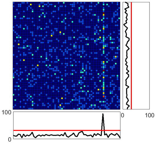
Figure 6.
The same “heat-map” shown in the left panel of Figure 1. Below and to the right of the main figure are shown one-dimensional histograms of particle counts created by collapsing the entire sample volume along the displayed vertical (for the histogram below the figure) or horizontal (for the histogram to the right of the figure) directions. The spike below the main figure clearly shows the much higher than expected count along the corresponding vertical line. Since the black curve exceeds the critical red line, the algorithm is designed to flag the entire displayed collection of drops.
Although there is evidence that raindrop arrivals are not perfectly random over ms to s long temporal scales and mm to m sized spatial scales (see, e.g., [23,39,40,41,42]), deviations on 2DVD measurement scales are still somewhat modest and, thus, Poisson statistics are treated as approximately valid here.
If raindrops were distributed perfectly randomly (following Poisson statistics) over the 2DVD measurement domain, then the probability that any one value in either histogram in Figure 6 would meet or exceed the red lines (marked at 33 drops) would be approximately equal to
(assuming that adding the terms with are negligible and that the unconstrained Poisson pdf is an acceptable approximation for this case). Similarly, the probability that any one point in part of either histogram in Figure 6 would contain a value of 3 or less would be
These probabilities lie at the heart of the algorithm developed to identify these anomalous regions; if any collection of 1000 drops has an element in either one-dimensional histogram that equals or exceeds 33—or has an element that is less than or equal to 3—then the entire collection of drops is flagged as “suspect” in the flagging code.
This method admittedly has a non-zero “false-positive” rate (some non-anomalous regions are erroneously flagged). The utilized critical values of “3 or less” and “33 or more” in the histograms are admittedly somewhat arbitrary but were selected to be consistent with visual inspection of questionable domains in a number of different data sets. (Indeed, the process of selecting 1000 drops at a time and dividing the field of view into 10 pixel by 10 pixel domains is also arbitrary; the parameters used in the algorithm were settled on by trial and error with real and simulated data sets that did and did not have the anomaly). For the present, we prefer to be conservative and flag potentially unaltered data as “suspect” rather than to allow potentially spurious data to make it through the algorithm unflagged. Future work is expected to include a refined flagging algorithm, but the method described here should enable rough approximations of anomaly impact and ubiquity.
In both the algorithm and in the analyses that follow, the choice was intentionally made to potentially overestimate the impact of this anomaly. We ultimately find the overall impact of the anomaly on rain measureables generally remains very small despite this overestimation—suggesting that 2DVD data largely remains reliable despite the ubiquity of this data anomaly.
The algorithm is designed to record up to three different (but not mutually exclusive) possible flags for each detected drop in each 2DVD data file:
- “During spurious extraneous interval”—Drop in question occurred during a period of time where extraneous drops were detected along one or more lines of pixels in the measurement area; all drops in the left panel of Figure 1 would be assigned this flag.
- “During spurious depleted interval”— Drop in question occurred during a period of time where there were anomalously few drops along one or more lines of pixels in the detection area. All drops in Figure 2 would be assigned this flag.
- “Spurious drop”—Drop in question occurred during a period of time where there were extraneous detected drops along one or more lines of pixels in the detection area and this drop was in the anomalous portion of the detection area. All detected drops along the vertical line in the left panel of Figure 1 would be assigned this flag, even though some are likely not spurious.
3.4. Ubiquity of the Anomaly
A total of 416 days of data from among the largest (most drops) available detected events were analyzed from a total of six different Compact 2DVDs (see Table 1). These data sets were gathered over the past several years at a variety of different locations and by different investigators. Nevertheless, every one of the 416 events examined showed some evidence of the anomaly demonstrated in Figure 1.

Table 1.
Summary information for anomaly statistics for the six 2DVD (The two-dimensional video distrometer) instruments studied. See the following sections to understand how lost accumulation percentage was estimated. Drops were removed if they had the “spurious drop” flag described above. (“CofC” stands for College of Charleston.)
In addition to assigning up to three different “flags” for each detected rain drop, our algorithm has been designed to explicitly identify questionable time intervals in the data record. Figure 7 shows these questionable time intervals as shaded regions throughout a sample storm’s drop accumulation record.
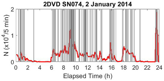
Figure 7.
The number of drops detected in 5 min intervals (marked in red) throughout an extended rain event on 2 January 2014 detected by 2DVD SN074. The gray regions indicate time periods during which some anomaly was detected. (Note that the red curve shows all drops detected, even if later flagged as spurious.)
The duration of each anomalous interval is hard to see when looking at a full day’s record; a half-hour subset of the data shown in Figure 7 is shown in Figure 8.
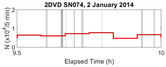
Figure 8.
Similar to Figure 7, except only a half-hour subset of the rain event is shown. Here, it is easier to see that the anomalous time intervals are generally short but have variable durations.
3.5. Characterizing the Anomalous Data Intervals
3.5.1. Data Set for Characterization Analysis
Although data from six different 2DVDs were used above to demonstrate the ubiquity of this anomaly, the majority of the data utilized was gathered by 2DVD SN074 which has been running mostly continuously in a single location near Hollywood, South Carolina since December 2013. This particular 2DVD is known to have been maintained following manufacturer recommendations by the authors and its performance has been frequently validated by reasonable agreement with a large number of other disdrometric instruments nearby, including (for part of the time) another 2DVD (SN098) located about 250 m away [17,23,25]. The detailed characterization that follows is based on the 252 events measured by 2DVD SN074. The number of detected anomaly time-intervals in these 252 dates ranged from 21–1398 with a median value of 153 anomalous intervals per rainy date. None of these SN074 data are expected to have detected frozen precipitation.
3.5.2. Number of Drops in Anomalous Data Intervals
Although the flagging algorithm is structured to look at groups of 1000 consecutive detected drops, the algorithm is designed to increment through the data set one drop at a time—so drop numbers 1–1000 are examined, then drop numbers 2–1001, etc. As such, problem intervals substantially shorter than 1000 drops are identifiable. Figure 9 shows the exceedance probability of anomalous data durations in terms of drop number. For example, approximately 28% of all detected anomalous intervals were more than 100 drops in duration. Each of the analyzed dates had an anomaly lasting at least 217 consecutive drops, with the median longest anomaly of the 252 data sets lasting 6548 consecutive drops.
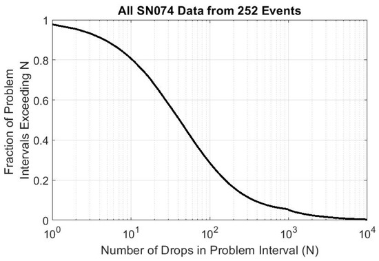
Figure 9.
The probability that any given anomalous data interval exceeds N drops. The median anomalous data interval length is about 41 drops, with only 5.2% of all anomalous data intervals exceeding 1000 drops. The mean anomalous data interval is 259.6 drops, with a standard deviation of 1221.6 drops.
Note that “false positives” (places where a region of the data set is erroneously flagged as anomalous due to random spatial fluctuations) will be very likely to report anomalies lasting only a few drops. If the flagging algorithm is tuned to lower the false-positive rate, the shape of the curve in Figure 9 may change substantially; the main point of Figure 9 is not in the details of the curve’s shape but rather to show that anomalies of less than thousands of drops are frequent.
The subtle “buckle” seen in the figure around 1000 drops is related to the flagging code’s structure of analyzing 1000 drops at a time; anomalies exceeding 1000 drops are slightly less sensitively detected in the current implementation of the flagging code, thus repressing the tail of the distribution somewhat. Despite the decreased sensitivity to anomalies lasting more than 1000 drops, 222 of the 252 events saw an anomaly exceeding 1000 drops in duration.
3.5.3. Duration of Anomalous Data Intervals
Perhaps of more physical concern is the temporal duration of these anomalies. Figure 10 breaks down the exceedance probability of anomalous data durations in terms of anomaly temporal duration. Again, we find that many anomalies are very brief, with the median detected anomaly lasting less than half of a second. A more refined flagging algorithm may modify this substantially, but the large number of brief-duration anomalies may indicate why these anomalies haven’t been previously identified.
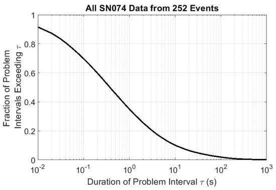
Figure 10.
The probability that any given anomalous data interval exceeds duration . The median anomalous data interval duration is about 0.37 s, with only 3.0% of all anomalous data intervals exceeding one minute. The mean anomalous data interval is 23.7 s, with a standard deviation of 617.4 s.
Despite the generally short duration of anomalous data segments, each data set examined had an anomaly lasting at least 13.7 s, with 126 (half) of the data sets having an anomaly of at least 399 s in duration.
3.5.4. Size Distribution of Anomalous Drops
In the SN074 data set examined here, only about 2.4% of all detected drops were flagged as “spurious drops”. Figure 11 explicitly compares the probability distribution of drop sizes of the spurious drops to that of all drops in the 252 day data set.
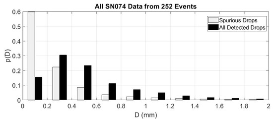
Figure 11.
A comparison of the probability distributions of drop diameters for all detected spurious drops (light gray) with the drop diameters of all drops (black) in the major rain events detected by 2DVD SN074.
Although spurious drops are seen at all detected drop sizes, over 90% of the spurious drops are at detected diameters less than or equal to 0.6 mm.
3.5.5. Vertical Fall Speeds of Anomalous Drops
The expected fall velocity of raindrops in still air has been known for quite some time [43,44]. Although substantial attention has recently been given to disdrometric measurement of non-terminal hydrometeor fall speeds and their possible physical origin [17,28,35,45,46,47,48], vertical fall-speed is suspected to be a reliable enough check on data fidelity that it is becoming increasingly common for investigators to use substantial deviations from terminal fall-speed as a way to filter out spurious 2DVD data [3,8,14,15,20,21,22,26].
Figure 12 shows the measured drop diameter-velocity scatterplot for SN074 2DVD data. All data from the 252 events are shown in black, the drops flagged as spurious are shown in red, and an empirical fit to the theoretical terminal fall-velocity relationship (following [49]) is shown in blue. Although many of the spurious drops have non-terminal velocities, (i) many of the spurious drops fall on the expected theoretical curve and (ii) many of the non-spurious drops deviate substantially from the theoretical expectation.
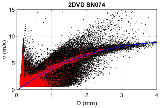
Figure 12.
A scatterplot of the measured drop diameter-fall velocity relationship for all 252 days of data examined from 2DVD SN074. All detected drops are shown in black, spurious drops are shown in red, and the expected relationship following [49] is shown in blue.
It would have been fortunate if the spurious drops could have easily been filtered out using a velocity filter similar to those employed in [3,8,14,15,20,21,22,31,36,50,51], but Figure 12 suggests that no such simple technique will work to find these spurious drops. Furthermore, previous studies that used a drop velocity filter likely still included many of the spurious drops identified in this study.
3.6. Bounding the Magnitude of the Anomaly
It is important to attempt to determine how much the anomaly explored here can influence disdrometric estimates of rain variables. It is impossible to know what the true values of drop counts and rain rates should have been when spurious data is present (or real data is missing). Here, we outline our best attempt to determine the anomaly’s maximum possible influence on the measured data.
A comprehensive analysis of the 252 events detected by 2DVD SN074 revealed that retained (non-spurious) drop counts with the “during spurious extraneous interval” flag outnumbered drops with the “during spurious depleted interval” flag by a factor of about 2.4:1, so we anticipate that the net effect of properly correcting for the anomaly would result in a net reduction of measured precipitation. Consequently, the choices described below are all intentionally designed to maximize the estimated losses in rain volume due to correcting for the anomaly. Our goal is not to determine what the true rain accumulations should have been, but rather to establish a reasonable upper bound for how much extra rain accumulation the anomaly might have been responsible for. As such, we expect all reported anomaly statistics to be overestimates.
3.6.1. Removing Spurious Drops
Throughout the analysis that follows, drops were removed if they were flagged as “spurious drops”. In removing all of these particles from the analysis, we likely overestimate the effect of the anomaly because some of the particles detected within that portion of the sample volume may not have been anomalous.
3.6.2. Accounting for Decreased Sensing Area
Estimating rainfall accumulations from the 2DVD requires the analyst to divide the volume of each detected drop by the estimated sample area associated with the detected drop. Thus, if there are N drops detected during a time interval , the rain depth accumulated during this time can be estimated via:
with the diameter of the ith drop and the effective sample area of the ith drop. can depend in a rather complicated way on , the drop’s position in the sample volume, and the presence or absence of other detected particles being detected simultaneously (see, e.g., [31]).
During periods of spurious particle detection along a line, removal of all particles along this line should reduce the effective sample area of all remaining particles within the measurement volume. Although a future version of our algorithm plans to account for this effect explicitly, the current flagging/processing algorithm neglects this effect. Correct lowering of for all non-spurious drops during these anomalous times would increase the estimated accumulation. By neglecting this effect, the approach used here again likely overestimates the effect of the anomaly.
3.6.3. Accounting for Missing Drops
Finally, we need to consider the effect of the drops that are “missing” from the data record. Particles flagged as “during spurious depleted interval” were assuredly accompanied by undetected particles within the parts of the sensing volume where sensitivity was diminished. Rather than make an ad hoc assumption regarding the number and properties of the drops that were missed, the present algorithm intentionally doesn’t consider the effect of these drops.
3.6.4. Rain Event Particle and Accumulation Losses
Based on the assumptions outlined above, Table 1 shows the fraction of drops removed as “spurious” and the net total removed accumulation percentage for each of six different 2DVD data sets. Although the effects on estimated accumulations are small, it is noteworthy that a sizeable percentage of all drops were detected during the anomalous time intervals (see Table 2).

Table 2.
The classification of all detected drops from the 252 events studied for 2DVD SN074. Note that though the total rain depth is estimated to be in error by less than 1% (see Table 1), a substantial fraction (2.5% + 9.2% + 3.8% = 15.5%) of all detected drops occurred during an anomalous time interval.
Although such a comprehensive look at the other five 2DVDs would be premature, some sense at the universality of these relationships can be obtained by looking at the individual rain events observed with the largest anomalies (Table 3). Despite the fact that the data set for SN074 is much larger (252 days of data compared to at most 45 days of data for the other five detectors), all of the other 2DVDs having events where a larger fraction of estimated rain accumulations were lost.

Table 3.
The events with the largest fraction of removed drops and the largest fraction of accumulation lost for each 2DVD studied. (SN025 and SN098 maximized the fraction of drops and fraction of total accumulations lost on the same date).
Figure 13 and Figure 14 explore the detector to detector prevalence of anomaly occurrence more fully. In general, it appears all 2DVDs have comparable losses and that there really doesn’t seem to be any obvious correlation between anomaly effect and event accumulation and/or drop number.
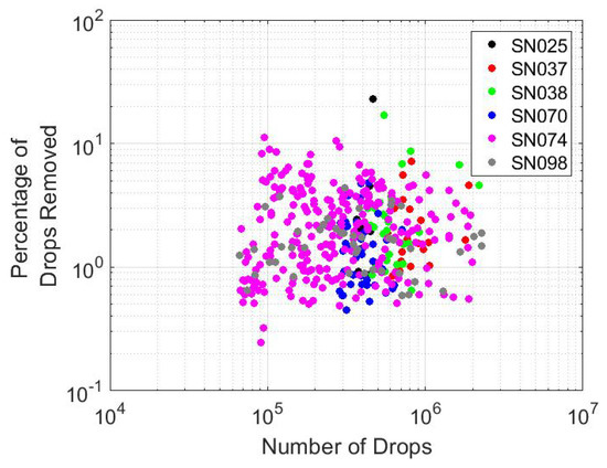
Figure 13.
A scatterplot of total spurious drop percentage vs. total detected drops for each of the events studied. Different 2DVDs are displayed with different colors. No obvious relationship between these two variables is evident, and differences between different 2DVDs are not obvious.
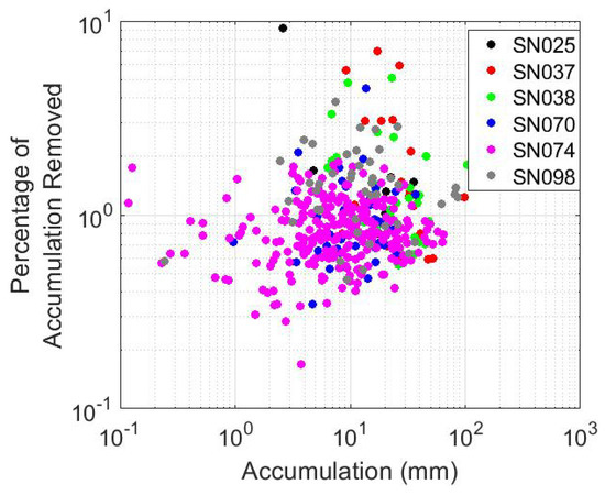
Figure 14.
Similar to Figure 13 but showing the fraction of total accumulation removed by excising the spurious drops vs. the total measured accumulation depth for each event. Again, no obvious relationship between these two variables is evident, and differences between different 2DVDs are not obvious.
Information regarding the deployment of the detectors (local geography, the presence/absence of nearby wind fencing, etc.) is insufficient to allow us to determine whether prevalence of the anomaly is related to wind, though an increase of spurious drops with increasing wind speed may be reasonable to expect.
4. Discussion
The anomaly identified here in 2DVD data is ubiquitous but typically modest in its impact on estimation of physically meaningful rain properties. None of the 416 events studied support rain accumulation errors of more than 9.1% due to this anomaly, even when the most pessimistic assumptions about the true underlying data have been made. Furthermore, typical errors in rain accumulation due to this effect appear to be on the order of no more than 1–2% of total rain accumulations.
The majority of the anomalous drops are very small in size. It has become increasingly common to filter out small 2DVD raindrop measurements due to questionable instrumental reliability within that domain anyway (see, e.g., [3,14,20,52]), and such a protocol will help control for this anomaly in future data analysis. Observations of SN074 data reveal that 90.4% of all detected spurious drops would be filtered out if only drops larger than 0.6 mm are retained. (However, applying this diameter filter only removes about 8.7% of the potentially spurious rain volume accumulation).
Due to the number of different variables the 2DVD software records, there are a number of ways to correct for these anomalies. For example, any of the following may be viable strategies to help improve data fidelity:
- Once anomalous time-intervals are flagged, processing codes can be written to utilize only the non-anomalous portion of the 2DVD in the measurement. This can be done relatively transparently to the end user by just modifying the effective area during these times and having the processing software automatically filter out the spurious drops.
- After flagging anomalous time-intervals, investigators have the ability to limit their analysis to data regimes where there are no detected anomalies.
- During anomalous time intervals, the rest of the data gathered during the same time can be used to try and estimate the missing data.
It is also possible that future versions of the 2DVD will incorporate a hardware change to make this anomaly disappear.
5. Conclusions
In summary, an anomaly has been identified in two-dimensional video disdrometer data. The physical origins of this anomaly are well understood, and its signature is clearly identifiable in all 2DVD data that the authors were able to readily access. It is relatively straightforward to flag data related to the anomaly for further analysis. The anomaly usually induces spurious detection of drops—most of which are less than 0.6 mm in diameter. The anomaly ultimately causes a slight overestimation of true rain accumulations—typically no larger than 1–2%—and doesn’t appear to be more prevalent in events with heavy rain accumulations or large drops. The fraction of anomalous data seems to be relatively stable among different 2DVDs, and cannot be completely filtered out by merely applying a diameter or fall-velocity filter to the measured data.
Author Contributions
M.L.L. led contributions associated with conceptualization, data curation, formal analysis, funding acquisition, investigation, project administration, resources, software, supervision, and writing the original draft. M.S. assisted with formal analysis, investigation, and wrote parts of the original draft. Both authors were involved in the review and editing tasks of the writing process.
Funding
This research was funded by the National Science Foundation through Grant No. 1532977 (M.L.L.).
Acknowledgments
Some of the data utilized in this study were sourced from field campaigns associated with the NASA Global Precipitation Measurement (GPM) mission science team. The authors would like to give their thanks to David Wolff at the NASA Wallops Field Support Office and John Kwiatkowski with George Mason University/NASA Goddard, and Günter Lammer, Joseph Niehaus, and Martin Schwinzerl for their help in keeping the College of Charleston 2DVD instruments running.
Conflicts of Interest
M.S. is employed by Joanneum (the company who manufactures the two-dimensional video disdrometer). The other author declares no conflict of interest.
References
- Gage, K.; Williams, C.; Johnston, P.; Ecklund, W.; Cifelli, R.; Tokay, A.; Carter, D. Doppler radar profilers as calibration tools for scanning radars. J. Appl. Meteorol. 2000, 39, 2209–2222. [Google Scholar] [CrossRef]
- Williams, C.; Kruger, A.; Gage, K.; Tokay, A.; Cifelli, R.; Krajewski, W.; Kummerow, C. Comparison of simultaneous rain drop size distributions estimated from two surface disdrometers and a UHF profiler. Geophys. Res. Lett. 2000, 27, 1763–1766. [Google Scholar] [CrossRef]
- Tokay, A.; Kruger, A.; Krajewski, W. Comparison of drop size distribution measurements by impact and optical disdrometers. Adv. Geosci. 2001, 30, 3–9. [Google Scholar] [CrossRef]
- Gage, K.; Williams, C.; Clark, W.; Johnston, P.; Carter, D. Profiler contributions to tropical rainfall measuring mission (TRMM) ground validation field campaigns. J. Atmos. Ocean. Technol. 2002, 19, 843–863. [Google Scholar] [CrossRef]
- Bringi, V.; Chandrasekar, V.; Hubbert, J.; Gorgucci, E.; Randeu, W.; Schönhuber, M. Raindrop size distribution in different climatic regions from disdrometer and dual-polarized radar analysis. J. Atmos. Sci. 2003, 60, 354–365. [Google Scholar] [CrossRef]
- Datta, S.; Jones, W.; Roy, B.; Tokay, A. Spatial variability of surface rainfall as observed from TRMM field campaign data. J. Appl. Meteorol. 2003, 42, 598–610. [Google Scholar] [CrossRef]
- Miriovsky, B.; Bradley, A.; Eichinger, W.; Krajewski, W.; Kruger, A.; Nelson, B.; Creutin, J.D.; Lapetite, J.M.; Lee, G.; Zawadzki, I.; et al. An experimental study of small-scale variability of radar reflectivity using disdrometer observations. J. Appl. Meteorol. 2004, 43, 106–118. [Google Scholar] [CrossRef]
- Thurai, M.; Bringi, V. Drop axis ratios from a 2D video disdrometer. J. Atmos. Ocean. Technol. 2005, 22, 966–978. [Google Scholar] [CrossRef]
- Krajewski, W.; Kruger, A.; Caracciolo, C.; Golé, P.; Barthes, L.; Creutin, J.D.; Delahaye, J.Y.; Nikolopoulos, E.; Ogden, F.; Vinson, J.P. DEVEX-disdrometer evaluation experiment: Basic results and implications for hydrologic studies. Adv. Water Resour. 2006, 29, 807–814. [Google Scholar] [CrossRef]
- Cao, Q.; Zhang, G.; Brandes, E.; Schuur, T.; Ryzhkov, A.; Ikeda, K. Analysis of video disdrometer and polarimetric radar data to characterize rain microphysics in Oklahoma. J. Appl. Meteorol. Climatol. 2008, 47, 2238–2255. [Google Scholar] [CrossRef]
- Cao, Q.; Zhang, G. Errors in estimating raindrop size distribution parameters employing disdrometer and simulated raindrop spectra. J. Appl. Meteorol. Climatol. 2009, 48, 406–425. [Google Scholar] [CrossRef]
- Yoshikawa, E.; Kida, S.; Yoshida, S.; Morimoto, T.; Ushio, T.; Kawasaki, Z. Vertical structure of raindrop size distribution in lower atmospheric boundary layer. Geophys. Res. Lett. 2010, 37, L20802. [Google Scholar] [CrossRef]
- Thurai, M.; Petersen, W.; Tokay, A.; Shultz, C.; Gatlin, P. Drop size distribution comparisons between Parsivel and 2-D video disdrometers. Adv. Geosci. 2011, 30, 3–9. [Google Scholar] [CrossRef]
- Tokay, A.; Petersen, W.; Gatlin, P.; Wingo, M. Comparison of raindrop size distribution measurements by collocated disdrometers. J. Atmos. Ocean. Technol. 2013, 30, 1672–1690. [Google Scholar] [CrossRef]
- Adirosi, E.; Gorgucci, E.; Baldini, L.; Tokay, A. Evaluation of Gamma raindrop size distribution assumption through comparison of rain rates of measured and radar-equivalent Gamma DSD. J. Appl. Meteorol. Climatol. 2014, 53, 1618–1635. [Google Scholar] [CrossRef]
- Ferretti, G.; Pichelli, E.; Gentile, S.; Maiello, I.; Cimini, D.; Davolio, S.; Miglietta, M.; Panegrossi, G.; Baldini, L.; Pasi, F.; et al. Overview of the first HyMeX special observation period over Italy: Observations and model results. Hydrol. Earth Syst. Sci. 2014, 18, 1953–1977. [Google Scholar] [CrossRef]
- Larsen, M.; Kostinski, A.; Jameson, A. Further evidence for super-terminal raindrops. Geophys. Res. Lett. 2014, 41, 6914–6918. [Google Scholar] [CrossRef]
- Gatlin, P.; Thurai, M.; Bringi, V.; Petersen, W.; Wolff, D.; Tokay, A.; Carey, L.; Wingo, M. Searching for large raindrops: A global summary of two-dimensional video disdrometer observations. J. Appl. Meteorol. Climatol. 2015, 54, 1069–1088. [Google Scholar] [CrossRef]
- Gires, A.; Tchiguirinskaia, I.; Schertzer, D.; Berne, A. 2DVD Data Revisited: Multifractal insights into cuts of the spatiotemporal rainfall process. J. Hydrometeorol. 2015, 16, 548–562. [Google Scholar] [CrossRef]
- Raupach, T.; Berne, A. Correction of raindrop size distributions measured by Parsivel disdrometers, using a two-dimensional video disdrometer as a reference. Atmos. Meas. Tech. 2015, 8. [Google Scholar] [CrossRef]
- Adirosi, E.; Volpi, E.; Lombardo, F.; Baldini, L. Raindrop size distribution: Fitting performance of common theoretical models. Adv. Water Resour. 2016, 96, 290–305. [Google Scholar] [CrossRef]
- Adirosi, E.; Baldini, L.; Roberto, N.; Gatlin, P.; Tokay, A. Improvement of vertical profiles of raindrop size distribution from micro rain radar using 2D video disdrometer measurements. Atmos. Res. 2016, 169, 404–415. [Google Scholar] [CrossRef]
- Jameson, A.; Larsen, M.; Kostinski, A. An example of persistent microstructure in a long rain event. J. Hydrometeorol. 2016, 17, 1661–1673. [Google Scholar] [CrossRef]
- Jensen, M.; Petersen, W.; Bansemer, A.; Bharadwaj, N.; Carey, L.; Cecil, D.; Collis, S.; DelGenio, A.; Dolan, B.; Gerlach, J.; et al. The midlatitude continental convective clouds experiment (MC3E). Bull. Am. Meteorol. Soc. 2016, 97, 1667–1686. [Google Scholar] [CrossRef]
- Larsen, M.; O’Dell, K. Sampling variability effects in drop-resolving disdrometer observations. J. Geophys. Res. Atmos. 2016, 121. [Google Scholar] [CrossRef]
- Roberto, N.; Adirosi, E.; Baldini, L.; Casella, D.; Dietrich, S.; Gatlin, P.; Panegrossi, G.; Petracca, M.; Sanò, P.; Tokay, A. Multi-sensor analysis of convective activity in central Italy during the HyMeX SOP 1.1. Atmos. Meas. Tech. 2016, 9, 535–552. [Google Scholar] [CrossRef]
- Thurai, M.; Gatlin, P.; Bringi, V. Separating stratiform and convective rain types based on the drop size distribution characteristics using 2D video disdrometer data. Atmos. Res. 2016, 169, 416–423. [Google Scholar] [CrossRef]
- Bringi, V.; Thurai, M.; Baumgardner, D. Raindrop fall velocities from an optical array probe and 2-D video disdrometer. Atmos. Meas. Tech. 2018, 11, 1377–1384. [Google Scholar] [CrossRef]
- D’Adderio, L.; Porcù, F.; Tokay, A. Evolution of drop size distribution in natural rain. Atmos. Res. 2018, 200, 70–76. [Google Scholar] [CrossRef]
- Nespor, V.; Krajewski, W.; Kruger, A. Wind-induced error of raindrop size distribution measurement using a two-dimensional video disdrometer. J. Atmos. Ocean. Technol. 2000, 17, 1483–1492. [Google Scholar] [CrossRef]
- Kruger, A.; Krajewski, W. Two-Dimensional Video Disdrometer: A Description. J. Atmos. Ocean. Technol. 2002, 19, 602–617. [Google Scholar] [CrossRef]
- Thurai, M.; Huang, G.; Bringi, V.; Randeu, W.; Schönhuber, M. Drop shapes, model comparisons, and calculations of polarimetric radar parameters in rain. J. Atmos. Ocean. Technol. 2007, 24, 1019–1032. [Google Scholar] [CrossRef]
- Schönhuber, M.; Lammer, G.; Randeu, W. One decade of imaging precipitation measurement by 2D-video-distrometer. Adv. Geosci. 2007, 10, 85–90. [Google Scholar] [CrossRef]
- Schönhuber, M.; Lammer, G.; Randeu, W. The 2D video disdrometer. In Precipitation: Advances in Measurement, Estimation and Prediction; Michaelides, S., Ed.; Springer: Berlin, Germany, 2008; pp. 3–31. [Google Scholar]
- Salles, C.; Creutin, J. Instrumental uncertainties in Z-R relationships and raindrop fall velocities. J. Appl. Meteorol. 2003, 42, 279–290. [Google Scholar] [CrossRef]
- Jaffrain, J.; Berne, A. Experimental quantification of the sampling uncertainty associated with measurements from PARSIVEL disdrometers. J. Hydrometeorol. 2011, 12, 352–370. [Google Scholar] [CrossRef]
- Tapiador, F.; Navarro, A.; Moreno, R.; Jiménez-Alcázar, A.; Marcos, C.; Tokay, A.; Durán, L.; Bodoque, J.; Martín, R.; Petersen, W.; DeCastro, M. On the optimal measuring area for pointwise rainfall estimation: A dedicated experiment with 14 Laser Disdrometers. J. Hydrometeorol. 2017, 18, 753–760. [Google Scholar] [CrossRef]
- World Meteorological Organization. Guide to Meteorological Instruments and Methods of Observation; WMO-No. 8; World Meteorological Organization: Geneva, Switzerland, 2010. [Google Scholar]
- Kostinski, A.; Jameson, A. Fluctuation properties of precipitation. Part I: On deviations of single-size drop counts from the Poisson distribution. J. Atmos. Sci. 1997, 54, 2174–2186. [Google Scholar] [CrossRef]
- Jameson, A.; Kostinski, A. Fluctuation properties of precipitation. Part IV: Finescale clustering of drops in variable rain. J. Atmos. Sci. 1999, 56, 82–91. [Google Scholar] [CrossRef]
- Jameson, A.; Kostinski, A. Fluctuation properties of precipitation. Part VI: Observations of hyperfine clustering and drop size distribution stuctures in three-dimensional rain. J. Atmos. Sci. 2000, 57, 373–388. [Google Scholar] [CrossRef]
- Jameson, A.; Larsen, M. Estimates of the statistical two-dimensional spatial structure in rain over a small network of disdromters. Meteorol. Atmos. Phys. 2016, 128, 401–413. [Google Scholar] [CrossRef]
- Gunn, R.; Kinzer, G. The terminal velocity of fall for water droplets in stagnant air. J. Meteorol. 1949, 6, 243–248. [Google Scholar] [CrossRef]
- Beard, K. Terminal velocity and shape of cloud and precipitation drops aloft. J. Atmos. Sci. 1976, 33, 851–864. [Google Scholar] [CrossRef]
- Hosking, J.; Stow, C. Ground-based measurements of raindrop fallspeeds. J. Atmos. Ocean. Technol. 1991, 8, 137–147. [Google Scholar] [CrossRef]
- Montero-Martinez, G.; Kostinski, A.; Shaw, R.; Garcia-Garcia, F. Do all raindrops fall at terminal speed? Geophys. Res. Lett. 2009, 36, L11818. [Google Scholar] [CrossRef]
- Thurai, M.; Bringi, V.; Petersen, W.; Gatlin, P. Drop shapes and fall speeds in rain: Two contrasting examples. J. Appl. Meteorol. Climatol. 2013, 52, 2567–2581. [Google Scholar] [CrossRef]
- Montero-Martinez, G.; Garcia-Garcia, F. On the behavior of raindrop fall speed due to wind. Q. J. R. Meterorol. Soc. 2016, 142, 2013–2020. [Google Scholar] [CrossRef]
- Foote, G.; DuToit, P. Terminal velocity of raindrops aloft. J. Appl. Meteorol. 1969, 8, 249–253. [Google Scholar] [CrossRef]
- Adirosi, E.; Baldini, L.; Lombardo, F.; Russo, F.; Napolitano, F.; Volpi, E.; Tokay, A. Comparison of different fittings of drop spectra for rainfall retrievals. Adv. Water Resour. 2015, 83, 55–67. [Google Scholar] [CrossRef]
- Testik, F.; Pei, B. Wind effects on the shape of raindrop size distribution. J. Hydrometeorol. 2017, 18, 1285–1303. [Google Scholar] [CrossRef]
- Tokay, A.; Kruger, A.; Krajewski, W.; Kucera, P.; Filho, A. Measurements of drop size distribution in the southwestern Amazon basin. J. Geophys. Res. 2002, 107, D20. [Google Scholar] [CrossRef]
© 2018 by the authors. Licensee MDPI, Basel, Switzerland. This article is an open access article distributed under the terms and conditions of the Creative Commons Attribution (CC BY) license (http://creativecommons.org/licenses/by/4.0/).