Abstract
The paper focuses on the area of experimental measurements for monitoring the impact of decarbonization on the technical and environmental parameters of the ICE. The condition for the implementation of the measurements was the selection of an ICE that had driven more than 300,790 km. During the laboratory tests, several test methods were used to assess the technical and emission conditions of the tested ICE with the code designation ALH, which is used in VOLKSWAGEN BORA vehicles. The technical parameters of the tested ICE (corrected power PNorm and torque MMom), emission parameters (absorption coefficient k and NOx emission) and fuel consumption parameters (specific fuel consumption bsfc) were compared and evaluated in the results. The results show that the decarbonization process on the tested vehicle VOLKSVWAGEN BORA 1.9 TDi affected the emission parameters but did not affect the technical parameters and specific fuel consumption.
1. Introduction
The matters of environmentalism and energetics are currently some of the most serious humanitarian problems and are related to so-called ecological safety. Safety is characterized as a feature of the object, i.e., machine, technology, activities, not to endanger either people or the environment [1]. At the same time, transport is clearly one of the biggest problem sectors. The increase in road traffic is a global problem in many cities [2]. The high rate of development of motorization, in addition to many advantages, creates ecological organic threats. The adverse effect of ICEs on the environment is determined, among others, by the estimation of harmful pollutants emission levels in relation to the limits set in the applicable legal acts [3]. Currently, more than half of the road transport fleet uses diesel engines, which are often identified as the primary source of air pollution [4]. At present, 99.8% of the world’s transport is powered by ICEs (ICE) and 95% of energy from transport comes from petroleum-derived liquid fuels. Many alternatives are being considered to reduce emissions in transport, including battery electric vehicles (BEV) and other fuels such as biofuels, synthetic fuels and hydrogen. However, many of the alternatives are gradually beginning to evolve and gain ground in the operation of mobile energy equipment. There are also some obstacles to their gradual introduction into mass use, so that 85–90% of transport energy is expected to come from conventional liquid fuels driving ICEs by 2040 [5]. It is therefore essential that design interventions for ICEs aim to reduce the local and global impact of transport on the environment. As stated by [6,7,8], the current research on compression ignition combustion engines is primarily oriented towards the use of alternative renewable fuels, reduction of toxic air emissions and the development of new engine diagnostic methods.
There are different approaches to the effort to reduce the environmental impact of transportation and agricultural machinery operation such as alternative fuels, electric vehicles, improved combustion engines or improving their technical condition [9,10,11]. Much room for such improvement is focused on assessing the various practical approaches that are already on the market. For example, the best spark ignition (SI) ICEs have a 14% lower fuel consumption than the average. The development of ICEs and conventional powertrains alone could reduce fuel consumption by more than 30% in Light Duty Vehicles (LDV). The implementation of other technologies, such as hybridization and vehicle weight reduction, could reduce fuel consumption by 50% compared to the current average for LDVs. Current exhaust after-treatment technology can ensure that the levels of pollutants in the exhaust gases meet the most stringent current emission requirements [5,12]. In the case of state-of-the-art diesel ICEs, the exhaust system in urban centers can be cleaner than the intake air.
Freight and passenger transport account for about 25% of global CO2 emissions from fossil fuel combustion [5]. In the European Union, for example, transport is responsible for almost 30% of the total carbon dioxide emissions, while 72% of CO2 emissions from the transport sector come from road transport activities. Of these emissions, 60.7% was emitted by passenger cars, 11.9% from light commercial vehicles, 26.2% from heavy duty vehicles and 1.2% from motorcycles [13,14]. In 2015, there were approximately 1.1 billion light commercial vehicles (LDVs) in the world, defined as vehicles weighing less than 3860 kg and approximately 380 million heavy goods vehicles [5]. In 2018, the world production of LDVs was about 70 million and for commercial vehicles it was about 25 million. The number of vehicles is increasing, especially in developing countries, and the number of LDVs in the world is expected to increase from 1.7 to 2 billion by 2040 [5,15]. At present, transport is almost exclusively (>99.8%) provided by mobile energy vehicles powered by ICEs: land and sea transport are carried out by means of reciprocating ICEs (ICE), while air transport is dominated by jet engines. ICEs also play important roles in industry and energy production. The energy source for driving the above-mentioned vehicles is provided by liquid fuels. There are currently many initiatives around the world to develop alternatives to conventional petroleum-based ICEs that are motivated by concerns about climate change and the local air quality associated with transport due to emissions of CO2, particulate matter, nitrogen oxides (NOx), carbon monoxide (CO) and hydrocarbons (HC). Of course, transport policy in many countries is also strongly influenced by the pursuit of economic growth, energy independence and energy security. An ICE could be replaced by a battery or fuel cell, with alternatives to conventional fuels including biofuels, natural gas, hydrogen, synthetic fuels, electric fuels, liquefied petroleum gas (LPG) and methanol [16,17].
Such alternatives need to be assessed on the basis of a life cycle analysis and will have serious environmental, economic and social consequences if alternatives are introduced prematurely [16]. For example, there is currently great interest in electrifying transport, but there are different degrees of electrification and the need for ICEs is eliminated only by a battery electric vehicle (BEV). However, the impact of BEVs on greenhouse gas emissions could be worse compared to conventional vehicles if the electricity generation and energy used to produce batteries, which depends on battery capacity and can be large, are not sufficiently decarbonized. Comparing BEVs with vehicles with ICEs is also difficult in terms of taking into account the source of the electrical energy. In many emerging economies, such as China and India, coal will play a significant role in energy production in the coming decades and the carbon intensity of energy production will be too high for BEVs to benefit from greenhouse gas emissions. In such countries, particulate matter, NOx and sulfur dioxide (SO2) emissions are even worse for BEVs, even if they are moved out of the vehicle. Thus, in the coming decades, global transport will be driven predominantly by ICEs using petroleum-based fuels [5,18,19]. It is essential to improve the efficiency and environmental impact of these engines in order to achieve significant and realistic improvements in transport sustainability. In fact, there is considerable scope for such improvements in the short term with better combustion, after-treatment and control systems and in the medium term with the development of new fuel/engine optimization systems. The vast existing transport infrastructure can be used to support such initiatives without the need for excessive changes or investments.
At the present time, when we are witnessing the promotion of battery electric vehicles, it is necessary to use all available technologies to mitigate the impact of transport on the environment and it is not appropriate to suspend the further development of ICEs and limit their sales. One way to mitigate the environmental impact of vehicles with ICEs is to keep their combustion chamber in good technical condition.
One of the ways that can ensure maintenance of the ICE parameters specified by the manufacturer (power, torque and fuel consumption) is the application of decarbonization. The conditions of operation of a combustion engine under actual traffic conditions are characterized by a wide range of engine speeds and torques. This has a direct impact on the vehicle fuel consumption and exhaust emissions that may be expressed with a variety of characteristics [20].
The process of engine decarbonization is starting to be used more and more often, but there are very few relevant scientific studies on its effectiveness [21,22,23]. For this reason, in the past we focused on monitoring performance parameters, consumption and exhaust emissions before and after decarbonization.
Among the scientific contributions of the process of decarbonization of ICEs, we can include the improvement of air quality and thus ensure the ecological safety of people, as ICEs produce harmful emissions such as nitrogen oxides (NOx), particulate matter (PM) and various organic compounds. The decarbonization of engines reduces the amount of these pollutants, improving air quality and reducing the risk of respiratory diseases and other health problems. For this reason, the attention of the authors was focused on evaluating the decarbonization process in terms of reducing NOx and the absorption coefficient. To assess the impact of decarbonization on the ICE, technical parameters of the engine, performance, torque and specific fuel consumption were also evaluated.
2. Materials and Methods
The aim of the experiment was to perform measurements of the technical and emission state of the ICE before and after decarbonization. In order to meet the set goals, it is necessary to characterize the input parameters of the measured object, the design of the measuring devices and the evaluation of selected technical and environmental parameters of the ICE before and after decarbonization.
Methods of Experimental Measurements
The experimental measurements were performed according to the procedure below:
- Carry out measurements of the technical, emission and fuel consumption of the ICE before decarbonization, which consisted of the following parts:
- (a)
- to perform a test of the emission state of an ICE using the free acceleration method in accordance with the Decree of the Ministry of Transport and Construction of the Slovak Republic No. 38/2022 Coll. on details of emission control [24],
- (b)
- measure ICE power while monitoring emissions and fuel consumption.
- Carry out decarbonization of the ICE.
- Carry out measurements of the technical, emission condition and fuel consumption of the ICE after decarbonization, which consisted of the following parts:
- (a)
- to perform a test of the emission state of an ICE using the free acceleration method in accordance with the Decree of the Ministry of Transport and Construction of the Slovak Republic No. 38/2022 Coll. on details of emission control,
- (b)
- measure ICE power while monitoring emissions and fuel consumption.
The VOLKSWAGEN BORA vehicle was selected to assess the impact of decarbonization on selected ICE output parameters. At the time of the tests, the vehicle had driven 300,790 km. The technical parameters of the above vehicle are given in Table 1.

Table 1.
Technical data VOLKSWAGEN BORA.
For the tested VOLKSWAGEN BORA vehicle, the manufacturer determined the parameters that must be observed when performing the emission control using the free acceleration method. Measurement conditions are given in Table 2.
Table 2.
Conditions for measuring the test vehicle VOLKSWAGEN BORA by the free acceleration method.
The Carbon Cleaner System CCS 1000 was used to decarbonize the ICE of the tested VOLKSWAGEN BORA vehicle (Figure 1 and Table 3).
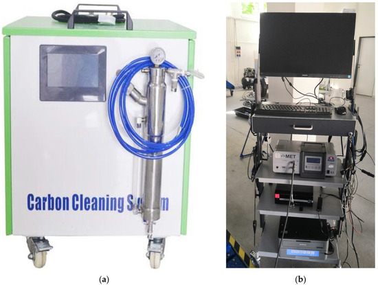
Figure 1.
(a) Carbon Cleaner System CCS 1000 decarbonization device for ICEs; (b) emission analyzer MAHA MET 6.
Table 3.
Technical data of the device for decarbonization of ICEs with Carbon Cleaner System CCS 1000.
The MAHA MET 6.3 emission analyzer was used to assess the emission status of the ICE before and after the decarbonization process. The technical data of the MAHA MET emission analyzer 6.3 are listed in Table 4.
Table 4.
Technical data of the MAHA MET emission analyzer 6.3.
The methodology of carbonization using CCS 1000 can be described as follows.
- Equipment preparation: The CCS 1000 includes a hydraulic vent and a hose connected to the engine intake manifold.
- Engine starting: The vehicle engine is started and warmed up to operating temperature.
- Hydrogen–oxygen mixing gas consumption: After engine warm-up, the hose from the CCS 1000 is connected to the intake manifold, allowing the hydrogen–oxygen mixture gas to flow into the combustion chamber.
- Hydrogen–oxygen mixture gas injection: A small amount of hydrogen–oxygen mixture of gas is injected into the combustion chamber. As the air mixture enters the combustion chamber, its components react with the carbon and coke that accumulate in the engine.
- Process completion: After decarbonization, the engine is shut down and disconnected from its CCS 1000.
Temperature vapor, hydrogen ions and oxygen ions, which are created from the mixing of gases in the combustion chamber (hydrogen and oxygen), participate in the process of removing deposits. The high-temperature vapor moistens and softens the tough carbon deposition on the surface of the engine chamber. The hydrogen ions restore the surface soft carbon deposition and form the carbon-based substances that are easy to combust. Then, these carbon-based substances combust sufficiently using the support of oxygen ions [25]. Hydrogen consumption: The amount of hydrogen normally consumed by the CCS 1000 can vary depending on factors such as the engine size, carbon content and specific operating conditions. Typical hydrogen consumption is 1 L, using up to 2 per hour.
The fuel consumption meter AIC-5004 was used to measure fuel consumption (Figure 2a). The measuring device is based on the volumetric principle of measuring the fuel consumption of diesel ICEs with an oscillating piston and a microprocessor that controls the pulse transmitter. The technical data of the consumption meter AIC-5004 are listed in Table 5.
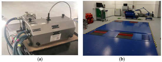
Figure 2.
(a) Fuel consumption meter AIC-5004; (b) dynamometer MAHA MSR 500/2 4WD.
Table 5.
Technical data of the fuel consumption meter AIC-5004.
Measurements of technical parameters of the ICE were performed with a MAHA MSR 500/2 4WD dynamometer (Figure 2b). The eddy current dynamometer is equipped with an electric cylinder drive, which is realized by one electric motor on each axle. The technical data of the MAHA MSR 500/2 4WD dynamometer are listed in Table 6.
Table 6.
Technical data of the MAHA MSR 500/2 4WD dynamometer.
The emission status and fuel consumption results were calculated with the expanded measurement uncertainty U, which is expressed as the standard measurement uncertainty multiplied by the coverage coefficient k = 2, which in a normal distribution corresponds to a coverage probability of approximately 95% and was set according to MSA 0104-97, respectively EA-4/02 M:2013.
3. Results
In order to meet the objectives of the article, it was necessary to design suitable instrumentation and build a measuring chain so that the measurements can be repeated. The proposed measuring string is shown in Figure 3.
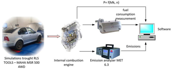
Figure 3.
Measuring chain for monitoring technical parameters, environmental parameters and fuel consumption.
3.1. Monitoring of the Emission State by the Free Acceleration Method before the Decarbonization Process
The emission condition and emission control of the diesel ICE of tested vehicle were verified by the free acceleration method in accordance with the Decree of the Ministry of Transport and Construction of the Slovak Republic No. 38/2022 Coll. on details of emission control [24]. The free acceleration test confirmed the satisfactory emission state of the diesel ICE. The results of the free acceleration test before the decarbonization process of the ICE are given in Table 7.
Table 7.
Average values of the absorption coefficient in the free acceleration method—before the decarbonization process.
The measurement using the free acceleration method did not exceed the specified maximum smoke engine limit Dmax, which is calculated for vehicles of categories M and N with the BKAT and NKAT emission systems as the sum of the corrected absorption coefficient XL and a constant of 0.5 m−1 in accordance with (1):
where: XL is the corrected absorption coefficient, m−1.
According to the above relationship, it is possible to determine the maximum permissible values of smoke Dmax for vehicles of categories M and N, which were first registered before 1 January 2008. If the vehicle was first registered after that date, then the value of maximum smoke Dmax is the same as the value of the corrected absorption coefficient XL and applies:
The tested vehicle was registered for the first time before 01.01.2008 and the manufacturer states the corrected factor XL = 0.9 m−1. The resulting value of smoke Dmax, according to relation (1) is 1.4 m−1.
During the monitoring of the emission state using the free acceleration method before the decarbonization process, the scattering value R, the maximum value of which must be less than or equal to 0.5 m−1, was not exceeded. The variance value of R was 76% lower compared to the maximum allowable value. The maximum allowable value of smoke Dmax determined according to Equation (1), which was compared with the value of the absorption coefficient k, was also not exceeded. The recorded average value of the absorption coefficient k was lower by 62% compared to the maximum permissible value of smoke Dmax.
3.2. Measurement of Technical Parameters, Emission Parameters and Fuel Consumption When Loading an ICE before the Decarbonization Process
The discrete measurement was performed according to a predetermined procedure, which was followed by each subsequent repeated measurement. The OBD diagnostic port was used as a source to obtain the speed used to calculate the power. In addition to continuous measurement, the cylindrical power test bench also allows the discrete measurement method to be used for power measurement. During the measurements, a discrete ICE loading method was used, during which it was possible to set the time for which the engine can stabilize under load at individual measurement points. The stabilization time (50 s) was determined depending on the speed of recording and processing of the monitored data by the measuring devices (emissions analyzer and fuel consumption meter). Data were monitored and recorded synchronously with the ICE load. Figure 4 and Figure 5 evaluate the discrete measurement process of a vehicle ICE.
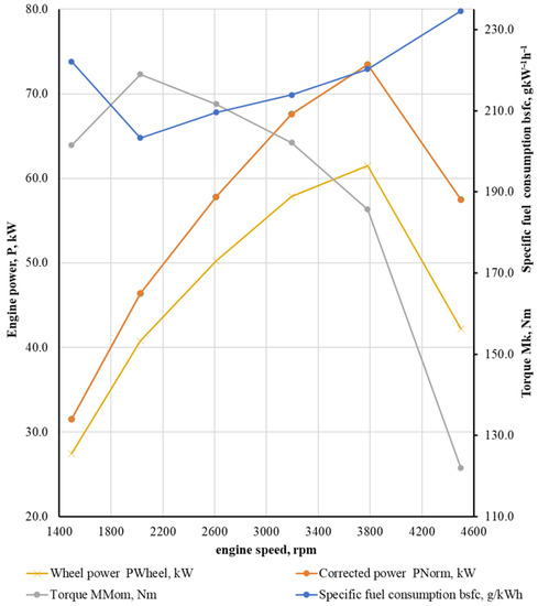
Figure 4.
Characteristics of the ICE before the decarbonization process.
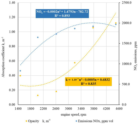
Figure 5.
Average recorded emissions of the ICE at its load before the decarbonization process.
From the measured results of the technical condition of the ICE with the code designation ALH, which is used in the VOLKSWAGEN BORA vehicle, it can be stated that the said ICE is in a satisfactory technical condition. This statement is also confirmed by a mutual comparison of data from the manufacturer with data measured in the Laboratory of Bioenergy Resources. The average value of the maximum measured torque was 3.8% higher compared to the manufacturer’s data. The stated average value of torque was measured at an engine speed of 2027 rpm, which is 6.3% higher than what the manufacturer states.
The average measured value of the maximum power, which was subsequently corrected according to the EWG 80/1269 standard, on the above-mentioned ICE was 10.6% higher than the value stated by the manufacturer. The above-average corrected power value was achieved at an average rated engine speed of 3777 rpm. The manufacturer states a speed of 3750 rpm.
Figure 5 shows the course of NOx emissions and absorption coefficient k during the discrete load of the ICE before the decarbonization process.
The average recorded NOx emission values and the absorption coefficient k were translated by a polynomial regression function. The polynomial function of the recorded NOx emissions for the test vehicle before the decarbonization process can be expressed as:
where: n is the speed of the ICE, rpm.
Based on the coefficient of determination, it is possible to determine the degree of tightness of the monitored dependence between NOx emissions and the speed of the ICE n under its load in a discrete manner. The coefficient of determination R2 = 0.893 was found for the recorded average values of NOx emissions during the discrete load of the ICE before the decarbonization process. The recorded coefficient of determination indicates a high degree of tightness of the above dependence, which reaches a value of 89.3%.
The coefficient of determination R2 = 0.835 was found for the recorded average values of the absorption coefficient k during the discrete load of the ICE before the decarbonization process. The polynomial function of the recorded absorption coefficient k for the test vehicle before the decarbonization process can be expressed as:
where: n is the speed of the ICE, rpm.
The recorded coefficient of determination indicates a very high degree of tightness of the above dependence, which reaches a value of 83.5%.
3.3. Decarbonization of the ICE
Before the decarbonization process itself, it was necessary to visually check the condition of the ICE, focusing on its intake, exhaust and fuel system. It was also necessary to check the oil level and ensure sufficient fuel. The fuel supply during the decarbonization process must be sufficient for 60 min at idle speed.
After visual inspection of the ICE and its subsequent start-up, it was necessary to connect the CCS 1000 decarbonization device to the intake system of the tested vehicle (Figure 6) via a connecting pipe and a wireless voltage sensor to the vehicle battery.
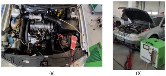
Figure 6.
Connection of the CCS 1000 decarbonization apparatus to the intake system of the test vehicle.
If all of the above steps have been performed, the decarbonization time must be set. After the decarbonization process had elapsed, the connecting pipe between the CCS 1000 decarbonization device and the intake system of the test vehicle had to be removed. It was also necessary to remove the wireless voltage sensor from the vehicle battery. The CCS 1000 device was powered from an external source, so connecting the device had no effect on the vehicle’s consumption.
To successfully complete the decarbonization process, it was necessary to remove any gas residues and deposits that could be present in the ICE system. The removal of the above residues was carried out by increasing the speed of the ICE from idle to 3500 rpm. This process was repeated 5 times.
3.4. Monitoring of the Emission State by the Free Acceleration Method after the Decarbonization Process
The emission condition and emission control of the diesel ICE of tested vehicle were verified by the free acceleration method in accordance with the Decree of the Ministry of Transport and Construction of the Slovak Republic No. 38/2022 Coll. on details of emission control [24]. The results of the free acceleration test after the decarbonization process of the ICE are given in Table 8.
Table 8.
Absorption coefficient values in the free acceleration method—after the decarbonization process.
After measurement using the free acceleration method, it was necessary to consider a corrected absorption coefficient XL = 0.9 m−1, which is given by the diesel combustion manufacturer, and a scattering value R, the maximum value of which must be less than or equal to 0.5 m−1. The resulting value of smoke Dmax according to Equation (1) is 1.4 m−1.
During the monitoring of the emission state using the free acceleration method before the decarbonization process, the scattering value R, the maximum value of which must be less than or equal to 0.5 m−1, was not exceeded. The variance value of R was 76% lower compared to the maximum allowable value. The maximum allowable value of smoke Dmax determined according to Equation (1), which was compared with the value of the absorption coefficient k, was also not exceeded. The recorded average value of the absorption coefficient k was lower by 84% compared to the maximum permissible value of smoke Dmax.
3.5. Measurement of Technical Parameters, Emission Parameters and Fuel Consumption When Loading an ICE after the Decarbonization Process
In Figure 7 and Figure 8 is an evaluation of the discrete measurement of the vehicle combustion engine ALH installed in the vehicle VOLKSWAGEN BORA.
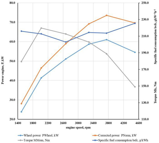
Figure 7.
Characteristics of the ICE after the decarbonization process.
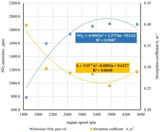
Figure 8.
Average recorded emissions of the ICE under its load after the decarbonization process.
From the measured results (Figure 7) of the technical condition of the ICE with the code designation ALH, which is installed in the VOLKSWAGEN BORA vehicle after the decarbonization process, the average value of the maximum measured torque was recorded as being 1.04% higher compared to the manufacturer’s data. The stated average torque value was measured at an engine speed of 2056 rpm, which is 7.6% higher than the manufacturer’s specifications.
The average measured value of the maximum power on the above-mentioned ICE, which was subsequently corrected according to the EWG 80/1269 standard, was 9.95% higher than the value stated by the manufacturer. The above-average corrected power value was achieved at an average nominal engine speed of 3893 rpm. The manufacturer states a speed of 3750 rpm.
The recorded average NOx emission and absorption coefficient k values were translated by a polynomial regression function. The polynomial function of the recorded NOx emissions for the test vehicle after the decarbonization process can be expressed as:
where: n is the speed of the ICE, rpm.
Based on the coefficient of determination, it is possible to determine the degree of tightness of the monitored dependence between NOx emissions and the speed of the ICE n under its load in a discrete manner. The coefficient of determination R2 = 0.9087 was found for the recorded average values of NOx emissions during the discrete load of the ICE after the decarbonization process. The recorded coefficient of determination indicated a very high degree of tightness of the above dependence, which reached the value of 90.97%.
One of the reasons why NOx emissions decreased after the decarbonization process, apart from the effect of carbon deposits on the combustion process (greater cleanliness of the combustion chamber and its parts), is that the EGR valve was also partially cleaned of impurities.
Exhaust gas recirculation (EGR) is a technique used to reduce nitrogen oxide (NOx) concentrations in internal combustion engines. It recirculates a portion of the engine’s exhaust gas back to the combustion chamber, mixed with the incoming air and fuel mixture. This process lowers the amount of oxygen available for combustion, reducing the peak combustion temperatures that can lead to NOx formation. EGR can reduce NOx emissions by up to 90% [26].
A coefficient of determination was found for the recorded average values of the absorption coefficient k during the discrete load of the ICE after the decarbonization process R2 = 0.8668. The polynomial function of the recorded absorption coefficient k for the test vehicle after the decarbonization process can be expressed as:
where: n is the speed of the ICE, rpm.
The recorded coefficient of determination indicated a very high degree of tightness of the above dependence, which reached the value of 86.68%.
The Comparisonsof individual monitored ICE parameters before and after the decarbonization process and individual monitored emission parameters before and after the decarbonization process are shown in Figure 9 and Figure 10.
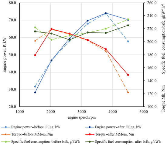
Figure 9.
Comparison of individual monitored ICE parameters before and after the decarbonization process.
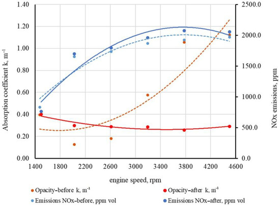
Figure 10.
Comparison of individual monitored emission parameters before and after the decarbonization process.
4. Conclusions
The content of this paper was focused on monitoring the effects of decarbonization and its impact on the technical and emission parameters of the tested ICE with the code ALH, which is used in the vehicle VOLKSWAGEN BORA 1.9 TDi. The tested vehicle had driven 300,790 km at the time of the tests. Experimental measurements were performed in accordance with the established measurement methodology, as described in the chapter “Materials and methods”.
Based on the results obtained on the above tested vehicle, it can be stated that the decarbonization process did not affect its technical parameters and specific fuel consumption. The deviations that were achieved with the mentioned parameters are negligible and are caused by the inaccuracy of the measuring instruments. The results obtained to assess the emission status of the tested vehicle VOLKSWAGEN BORA 1.9 TDi, which is equipped with a diesel ICE codenamed ALH, confirmed that the decarbonization process has an impact on the monitored emission values. During the emission state test by the free acceleration method performed in accordance with the Decree of the Ministry of Transport and Construction of the Slovak Republic No. 38/2022 Coll. on the details of the emission control, it can be stated that the values of the absorption coefficient k decreased after the decarbonization process by 51.9%. In addition to the absorption coefficient k, NOx emissions were recorded during the discrete loading of the ICE. The values of the absorption coefficient k decreased by 20.4% and the emissions of nitrogen oxides NOx decreased by 2.04%.
From the achieved results, it can be concluded that one of the ways to keep the ICE in good technical condition is the use of decarbonization. However, testing on a larger number of vehicles would be necessary to confirm the above statement.
Author Contributions
Conceptualization and writing (original draft preparation), J.J. and J.T.; methodology, J.J., J.T. and S.B.; formal analysis, Z.T., J.K. (Ján Kosiba), Š.Č. and K.K.; writing—review and editing, J.J. and J.T.; visualization, P.K., J.K. (Jerzy Kaszkowiak), M.T. and M.P. All authors have read and agreed to the published version of the manuscript.
Funding
This research received no external funding.
Institutional Review Board Statement
Not applicable.
Informed Consent Statement
Not applicable.
Data Availability Statement
The data presented in this study are available on request from the corresponding author.
Acknowledgments
This publication was supported by the Operational Program Integrated Infrastructure within the project: Demand-driven research for the sustainable and innovative food, Drive4SIFood 313011V336, cofinanced by the European Regional Development Fund.
Conflicts of Interest
The authors declare no conflict of interest.
References
- Sloboda, A.; Pil’a, J.; Sloboda, O.; Korba, P.; Hovanec, M.; Rácek, B. Vibrodiagnostic of aircraft hydraulic emergency hydrogenerator NP 27T. Eng. Fail. Anal. 2022, 138, 106337. [Google Scholar] [CrossRef]
- Janoško, I.; Kuchar, P. Evaluation of the fuel commercial additives effect on exhaust gas emissions, fuel consumption and performance in diesel and petrol engine. Agron. Res. 2018, 16, 3. [Google Scholar] [CrossRef]
- Niezawodność, A.K.-E. Exhaust Emission Test Performance with the Use of the Signal from Air Flow Meter. Eksploat. I Niezawodn. 2015, 17, 129–134. [Google Scholar]
- Pourdarbani, R.; Ardabili, S.; Akbarpouran, E.; Hernandez-Hernandez, J.L. Exergo-Environmental Optimization of a Diesel Engine. Acta Technol. Agric. 2022, 25, 157–168. [Google Scholar] [CrossRef]
- Leach, F.; Kalghatgi, G.; Stone, R.; Miles, P. The scope for improving the efficiency and environmental impact of internal combustion engines. Transp. Eng. 2020, 1, 100005. [Google Scholar] [CrossRef]
- Martinez-Valencia, L.; Camenzind, D.; Wigmosta, M.; Garcia-Perez, M.; Wolcott, M. Biomass supply chain equipment for renewable fuels production: A review. Biomass-Bioenergy 2021, 148, 106054. [Google Scholar] [CrossRef]
- Martins, J.; Brito, F.P. Alternative Fuels for Internal Combustion Engines. Energies 2020, 13, 4086. [Google Scholar] [CrossRef]
- Mikulski, M.; Wierzbicki, S.; Niezawodność, A.P.-E. Zero-Dimensional 2-Phase Combustion Model in a Dual-Fuel Compression Ignition Engine Fed with Gaseous Fuel and a Divided Diesel Fuel Charge. Eksploat. I Niezawodn. 2015, 17, 42–48. [Google Scholar] [CrossRef]
- Angelovič, M.; Jablonický, J.; Tkáč, Z.; Angelovič, M. Comparison of Smoke Emissions in Different Combustion Engine Fuels. Acta Technol. Agric. 2020, 23, 201–207. [Google Scholar] [CrossRef]
- Čedík, J.; Pexa, M.; Peterka, B.; Holůbek, M.; Mader, D.; Pražan, R. Effect of Biobutanol-Sunflower Oil-Diesel Fuel Blends on Combustion Characteristics of Compression Ignition Engine. Acta Technol. Agric. 2018, 21, 130–135. [Google Scholar] [CrossRef]
- Nadykto, V.; Findura, P.; Kyurchev, V.; Orel, O. Influence of Biodiesel on Performance of Machine-Tractor Units. Acta Technol. Agric. 2022, 25, 7–12. [Google Scholar] [CrossRef]
- Hashemi, F.; Pourdarbani, R.; Ardabili, S.; Hernandez-Hernandez, J.L. Life Cycle Assessment of a Hybrid Self-Power Diesel Engine. Acta Technol. Agric. 2023, 26, 17–28. [Google Scholar] [CrossRef]
- Sebos, I. Fossil Fraction of CO2 Emissions of Biofuels. Carbon Manag. 2022, 13, 154–163. [Google Scholar] [CrossRef]
- Annual European Union Greenhouse Gas Inventory 1990–2019 and Inventory Report 2021—European Environment Agency. Available online: https://www.eea.europa.eu/publications/annual-european-union-greenhouse-gas-inventory-2021 (accessed on 5 October 2022).
- International Energy Outlook 2019 with Projections to 2050. Available online: https://slidetodoc.com/international-energy-outlook-2019-with-projections-to-2050-2/ (accessed on 5 October 2022).
- Kalghatgi, G. Is It Really the End of ICEs and Petroleum in Transport? Appl. Energy 2018, 225, 965–974. [Google Scholar] [CrossRef]
- Senecal, P.K.; Leach, F. Diversity in Transportation: Why a Mix of Propulsion Technologies Is the Way Forward for the Future Fleet. Results Eng. 2019, 4, 100060. [Google Scholar] [CrossRef]
- Fuinhas, J.A.; Koengkan, M.; Leitão, N.C.; Nwani, C.; Uzuner, G.; Dehdar, F.; Relva, S.; Peyerl, D. Effect of Battery Electric Vehicles on Greenhouse Gas Emissions in 29 European Union Countries. Sustainability 2021, 13, 13611. [Google Scholar] [CrossRef]
- MaMa, H.; Balthasar, F.; Tait, N.; Riera-Palou, X.; Harrison, A. A new comparison between the life cycle greenhouse gas emissions of battery electric vehicles and internal combustion vehicles. Energy Policy 2012, 44, 160–173. [Google Scholar] [CrossRef]
- Merkisz, J.; Rymaniak, Ł. The Assessment of Vehicle Exhaust Emissions Referred to CO2 Based on the Investigations of City Buses under Actual Conditions of Operation. Eksploat. I. Niezawodn. 2017, 19, 522–529. [Google Scholar] [CrossRef]
- Gill, S.S.; Chatha, G.S.; Tsolakis, A.; Golunski, S.E.; York, A.P.E. Assessing the effects of partially decarbonising a diesel engine by co-fuelling with dissociated ammonia. Int. J. Hydrogen Energy 2012, 37, 6074–6083. [Google Scholar] [CrossRef]
- Wright, M.L.; Lewis, A.C. Decarbonisation of heavy-duty diesel engines using hydrogen fuel: A review of the potential impact on NOx emissions. Environ. Sci. Atmos. 2022, 2, 852–866. [Google Scholar] [CrossRef]
- Devalekar, P.; Bagkar, M.; Jadhav, A.; Manchikatla, K.; Rawool, S. Review on Engine Decarbonisation Process. Int. J. Innov. Res. Sci. Technol. 2016, 3, 173–177. [Google Scholar]
- Methodological Instruction no. 38/2022, Amending Methodological Instruction no. 2/2020 for Carrying Out Regular Emission Control of Motor Vehicles with a Petrol Engine with an Unimproved Emission System, with a Petrol Engine with an Improved Emission System and with Diesel Engine as Amended. Available online: https://www.seka.sk/storage/app/media/stranky/legislativa/metodiky/2023/mp-38-2022.pdf (accessed on 2 August 2023).
- Okay Energy. Available online: https://www.okayenergy.com/oxyhydrogen/hho-engine-carbon-cleaning-machine.html (accessed on 3 August 2023).
- Abdelhameed, E.; Tashima, H. EGR and Emulsified Fuel Combination Effects on the Combustion, Performance, and NOx Emissions in Marine Diesel Engines. Energies 2023, 16, 336. [Google Scholar] [CrossRef]
Disclaimer/Publisher’s Note: The statements, opinions and data contained in all publications are solely those of the individual author(s) and contributor(s) and not of MDPI and/or the editor(s). MDPI and/or the editor(s) disclaim responsibility for any injury to people or property resulting from any ideas, methods, instructions or products referred to in the content. |
© 2023 by the authors. Licensee MDPI, Basel, Switzerland. This article is an open access article distributed under the terms and conditions of the Creative Commons Attribution (CC BY) license (https://creativecommons.org/licenses/by/4.0/).