Review

Application and Development of Selective Catalytic Reduction Technology for Marine Low-Speed Diesel Engine: Trade-Off among High Sulfur Fuel, High Thermal Efficiency, and Low Pollution Emission

1
College of Power and Energy Engineering, Harbin Engineering University, Harbin 150001, China
2
Wenzhou Office, China Classification Society, Wenzhou 325000, China
*
Author to whom correspondence should be addressed.
Atmosphere 2022, 13(5), 731; https://doi.org/10.3390/atmos13050731
Submission received: 16 March 2022 / Revised: 16 April 2022 / Accepted: 27 April 2022 / Published: 2 May 2022
(This article belongs to the Special Issue Shipping Emissions and Air Pollution)

Abstract

:
In recent years, the International Maritime Organization (IMO), Europe, and the United States and other countries have set up different emission control areas (ECA) for ship exhaust pollutants to enforce more stringent pollutant emission regulations. In order to meet the current IMO Tier III emission regulations, an after-treatment device must be installed in the exhaust system of the ship power plant to reduce the ship NOx emissions. At present, selective catalytic reduction technology (SCR) is one of the main technical routes to resolve excess NOx emissions of marine diesel engines, and is the only NOx emission reduction technology recognized by the IMO that can be used for various ship engines. Compared with the conventional low-pressure SCR system, the high-pressure SCR system can be applied to low-speed marine diesel engines that burn inferior fuels, but its working conditions are relatively harsh, and it can be susceptible to operational problems such as sulfuric acid corrosion, salt blockage, and switching delay during the actual ship tests and ship applications. Therefore, it is necessary to improve the design method and matching strategy of the high-pressure SCR system to achieve a more efficient and reliable operation. This article summarizes the technical characteristics and application problems of marine diesel engine SCR systems in detail, tracks the development trend of the catalytic reaction mechanism, engine tuning, and control strategy under high sulfur exhaust gas conditions. Results showed that low temperature is an important reason for the formation of ammonium nitrate, ammonium sulfate, and other deposits. Additionally, the formed deposits will directly affect the working performance of the SCR systems. The development of SCR technology for marine low-speed engines should be the compromise solution under the requirements of high sulfur fuel, high thermal efficiency, and low pollution emissions. Under the dual restrictions of high sulfur fuel and low exhaust temperature, the low-speed diesel engine SCR systems will inevitably sacrifice part of the engine economy to obtain higher denitrification efficiency and operational reliability.

1. Introduction

Based on the consideration of ship operating costs, the ship engines generally burn low-quality fuel. Low-quality fuel oil includes Intermediate Fuel Oil (IFO) and Heavy Fuel Oil (HFO). Low-quality fuel oil is a mixture of Residual Oil (RO) after distillation by petroleum and Marine Diesel Oil (MDO). In a certain proportion, it has high viscosity, high sulfur content, high residual carbon, and heavy metals (cadmium, vanadium, and lead, etc.).
Due to the use of low-quality fuel in ship engines, the exhaust gas emitted by its combustion must contain a large amount of nitrogen oxides (NOx), sulfur oxides (SOx), carbon dioxide (CO2), particulate matter (PM), volatile organic compounds (VOC), and many other pollutants, causing serious pollution to the marine environment and the port atmosphere. Its emissions are shown in Table 1 [1]. Among them, nitrogen oxides, sulfur oxides, and carbon dioxide are corrosive gases, which can easily cause pollution problems such as acid rain and photochemical smog and exacerbates the greenhouse effect. Additionally, these five pollutants will stimulate the central nervous system and respiratory system of the human body, causing adverse effects on human health. Furthermore, the main emissions from diesel engines are smoke emissions and nitrogen oxides. The reaction between atmospheric nitrogen and smoke emissions occurs at high temperatures, and smoke emissions are high in the oil-rich areas within the engine cylinders. The main challenge for compression ignition engines is to simultaneously reduce smoke and NOx emissions [2].
According to statistics, marine diesel engines emit about 20 million tons of NOx, 10 million tons of SOx, and 1 million tons of PM every year [3]. In addition, NOx, SO2, and CO2 emissions from ships account for 15%, 4–9%, and 2.7% of global anthropogenic pollution, respectively [4]. With the development of shipping industry and trade, ship power plants have become one of the main air pollution sources, and the removal of nitrogen oxides is still the core of ship exhaust pollution control.
However, recent surveys have shown that ships take longer in transit because they do not route close to the coast and emit a wider range of pollutants. As a result, global and regional gaseous pollutants including carbonaceous species, PM, carbon monoxide (CO), NOx, PAHs, hydrocarbons (HCs), SO2, and VOCs greatly affect the local air quality [5]. Therefore, in order to improve the emission of marine diesel engines, it is an effective measure to use environmentally friendly alternative new fuels and implement efficient after-treatment system technology under different working conditions. Among the after-treatment systems, Abdulfatah Abdu Yusuf et al. [6] studied the use of diesel particulate filters (DPF), diesel exhaust fluid (DEF), and selective catalytic regulation (SCR) to effectively regulate ultrafine particles (UFP), PM, HC, and NOx emissions so as to achieve MARPOL Annex VI and US EPA Tier III-IV emission standards for marine diesel engines Category 1–2.
In order to reduce the pollution of the ship exhaust to the environment and the atmosphere, the IMO, Europe, and the United States and other countries have formulated strict regulations on ship exhaust pollutants. They also enforce stricter NOx and SOx emission standards in designated emission control areas, which directly affects relevant ports and routes in Europe and North America. At the same time, the Ministry of Transport of China established the Pearl River Delta, Yangtze River Delta, and Bohai Rim (Beijing–Tianjin–Hebei) waters as the ship air pollutant emission control areas in 2016 [7].
In order to meet the current IMO Tier III emission regulations, an after-treatment device must be installed in the exhaust system of the ship power plant to reduce the ship NOx emissions. Currently, SCR technology and exhaust gas recirculation (EGR) technology are the most practical technologies to solve NOx emissions of marine diesel engines and make them meet the IMO Tier III standard [8]. However, in terms of technology maturity and scope of application, SCR technology is the only NOx reduction technology recognized by the International Maritime Organization that can be used for various ship engines and ship types.
As western countries began to study SCR technology very early, they have mastered the more advanced marine diesel engine SCR technology, and many products have already been installed on ships and started to operate. At present, MAN is the only manufacturer that can simultaneously provide high-pressure SCR (HP-SCR) and EGR treatment solutions. In 2011, the MAN company cooperated with Hitachi Zosen Corporation to develop a marine high-pressure SCR system, which was verified on the 6S46MC-C8 diesel engine. On 25 February 2019, MAN announced its first order for HP-SCR products: MES m ordered three HP-SCR units for the construction of three 87k DWT bulk carriers to meet IMO Tier III emission standards for their engines [9]. WinGD is developing a more compact and integrated HP-SCR scheme, where the SCR reactor is located on the engine. Therefore, compared with the standard Tier II engine, this scheme only slightly increases the space requirements in the cabin [10].
Furthermore, the research direction of marine diesel engine SCR technology mainly includes the design of the flow field structure of the SCR system, the optimization and the control strategy of the urea spray model, the structural performance of the reaction catalysts, and the structure optimization of the SCR mixer and the SCR reactor. Bartosz Kaźmierski et al. [11] have developed a urea SCR system without a conventional mixer. The system can fully decompose urea and obtain uniform ammonia distribution at the catalyst inlet, while minimizing liquid film deposition and maintaining a compact design. Sadashiva Prabhu et al. [12] pointed out the importance of the mixing zone length and the urea injection point position. If the above parameters are properly defined, more NH3 may be obtained at the catalyst inlet. Through numerical analysis, it was found that the advantages of increasing the spray angle are enhanced evaporation rate of aqueous solution and increased ammonia concentration. The numerical and experimental analysis carried out by Cho et al. [13] included the arrangement of multiple mixers and decomposition sections to explore the uniformity of ammonia distribution and NOx conversion efficiency in the Urea-SCR system. The results showed that the application of a static mixer composed of blades significantly improved the ammonia distribution, and the generated turbulent vortex promoted the decomposition of urea aqueous solution (UWS). Steffen Tischer et al. [14] studied the formation and decomposition of liquid and solid by-products that were detrimental to the catalyst in the automotive exhaust pipe using SCR technology through thermogravimetric analysis and differential scanning calorimetry. A new reaction scheme is proposed, which emphasizes the thermodynamic equilibrium of liquid and solid phase reactants. Huang et al. [15] analyzed the formation of liquid film and solid deposit in urea SCR system through numerical simulation. The mixing device was optimized to improve the ammonia uniformity and velocity uniformity at the SCR inlet, and reduce the pressure drop of the system. Some improvements were made in the evaluation indexes considered. In addition, the design reduces liquid film deposition. By analyzing the detailed reaction network framework for the formation of urea deposits, Mo et al. [16] constructed a sub-model of urea decomposition and sediment formation, and calculated the urea decomposition section of the exhaust pipe of the urea-selective catalytic reduction system. The detailed mechanism preliminarily explored can basically reflect the change law of urea conversion to ammonia and some main intermediate products. In view of the fact that the exhaust pipe walls of diesel engine equipped with SCR system easily produces sediment, resulting in the decrease in urea economy and NOx conversion efficiency, Lv et al. [17] established a simulation model for quantitatively calculating the sediment generation rate of exhaust pipe wall, and revealed the influence of various factors on sediment productivity through single factor simulation.
In conclusion, the published studies on the SCR reaction mechanism mainly focused on low sulfur and low-pressure exhaust gas conditions of diesel engines. However, low-speed diesel engines burn high sulfur inferior residual oil, and the SCR system located in front of the turbine is often in harsh working conditions such as low temperature, high sulfur, and high pressure, which makes the actual operating efficiency much lower than the design efficiency and causes practical problems such as crystallization of ammonium salt. Therefore, the study of SCR reaction mechanism under the limiting conditions of high pressure and high sulfur is an important theoretical basis for solving the practical application problems of low-speed diesel engines. This article discusses the technical characteristics and application problems of the marine SCR systems in detail, tracks the development trend of the catalytic reaction mechanism and engine tuning strategy under high sulfur conditions, and predicts that the development of SCR technology for marine low-speed engines should be the compromise solution under the requirements of high sulfur fuel, high thermal efficiency, and low pollution emissions. Under the dual restrictions of high sulfur fuel and low exhaust temperature, the low-speed diesel engine SCR systems will inevitably sacrifice part of the engine economy to obtain higher denitrification efficiency and operational reliability.

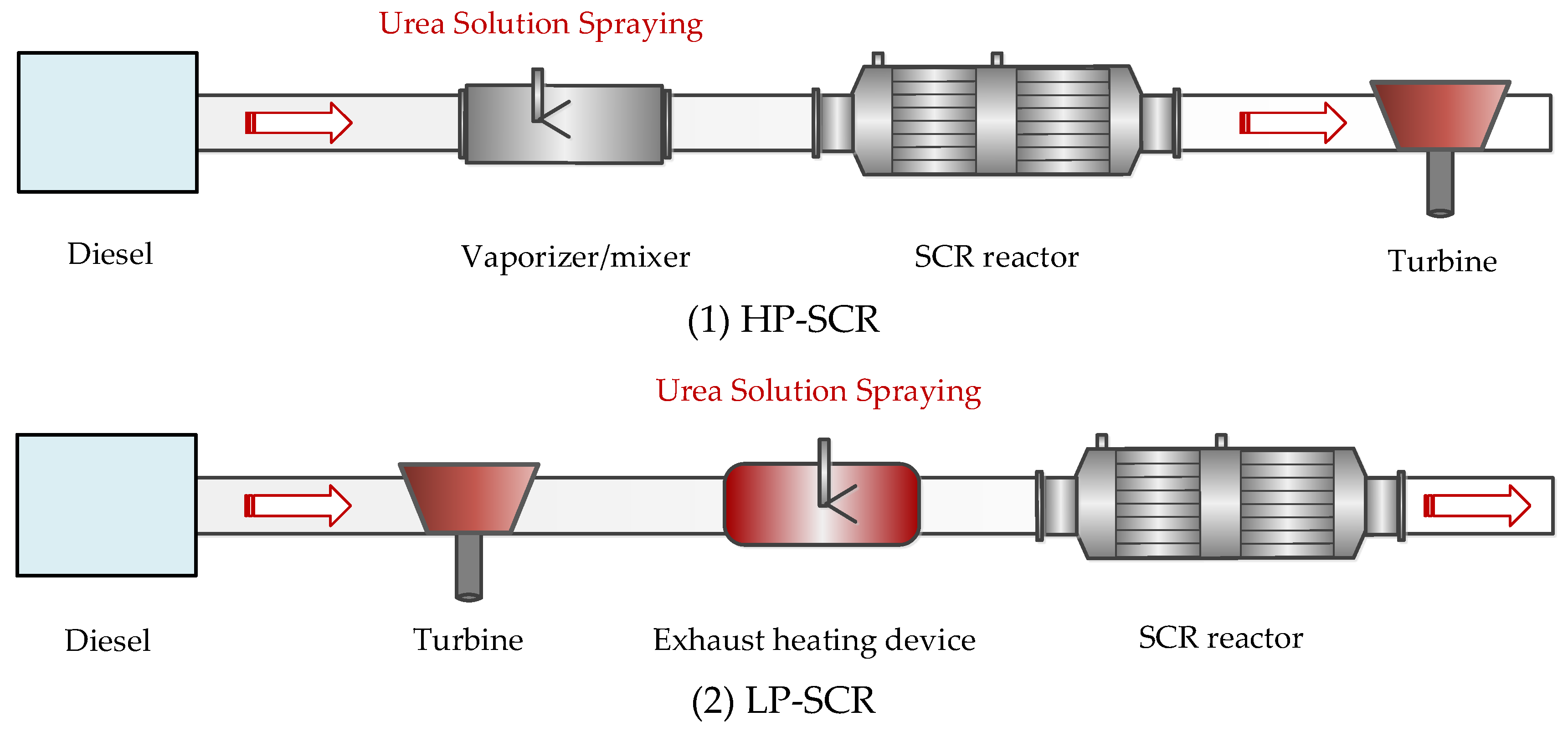
2. Classification of the Marine Selective Catalytic Reduction (SCR) Systems

The marine SCR system is mainly composed of a urea solution injection system, mixer, SCR reactor, measurement system, and soot blowing system [18]. The urea solution injection system is composed of a urea storage tank, urea injection pump, nozzle, valve, and pipeline. Additionally, a static mixer is arranged in the exhaust pipe of the marine SCR system to improve the mixing uniformity of exhaust gas and ammonia gas. It is mainly composed of some baffles with different directions. By changing the airflow direction of the exhaust gas, it causes turbulent flow in different directions. This method can make the urea move and mix rapidly in the radial direction and increase the uniformity of the concentration distribution of the cross-section. Although the mixer can fully mix the exhaust gas and ammonia gas, it will also cause a certain pressure loss. The reactor is the core site for the selective catalytic reduction reaction, which is mainly composed of the reactor shell, catalyst, soot blowing unit, and various sensors. The catalyst in the reactor is generally a modular packaged catalyst, which can be easily replaced. At the same time, the catalyst is installed inside the reactor. The installation position and structure of the catalyst in the reactor can be designed according to the different application sites and space size of the SCR system. By optimizing the design, the mixing uniformity of ammonia gas and exhaust gas can be improved as much as possible.
The selective catalytic reduction technology uses ammonia (NH3) to reduce NOx. It selectively reacts with the NOx in diesel exhaust gas to produce harmless substances N2 and H2O within the temperature range of 280–420 °C and under the action of a catalyst, so as to achieve the purpose of removing NOx [19]. As the urea-water solution (UWS) has no significant harm and the supply system is easy to install, it is widely used as the reducing agent for selective catalytic reduction reactions [20]. At present, the decomposition reaction process of urea is generally simplified to the following reactions:
Water evaporation of urea solution:
NH 2 - CO - NH 2 x H 2 O NH 2 - CO - NH 2 + x H 2 O
Urea pyrolysis reaction:
NH 2 - CO - NH 2 NH 3 + NHCO
Hydrolytic reaction of isocyanic acid:
HNCO + H 2 O NH 3 + CO 2
Therefore, the total reaction of urea decomposition is:
NH 2 - CO - NH 2 NH 3 + CO 2 + x H 2 O  
The urea solution is finally decomposed to produce reaction gas NH3, which is mixed evenly with the tail gas, and enters the SCR reactor for a denitration reaction.
Due to the low exhaust temperature and high sulfur amount of the exhaust gas from the marine diesel engine, the denitration efficiency of the marine SCR system is strongly limited. At present, marine diesel SCR systems, especially two-stroke low-speed diesel SCR systems, mainly achieve higher denitration efficiency by increasing the temperature of the reaction gas to meet the requirements for marine diesel engine emission control [21].
According to the arrangement of the SCR system, the marine SCR system can be divided into the high-pressure SCR (HP-SCR) system arranged in front of the turbocharger and the low-pressure SCR (LP-SCR) system arranged after the turbocharge [22,23]. Figure 1 shows a flowchart of a HP-SCR system and a LP-SCR system on a marine diesel engine.

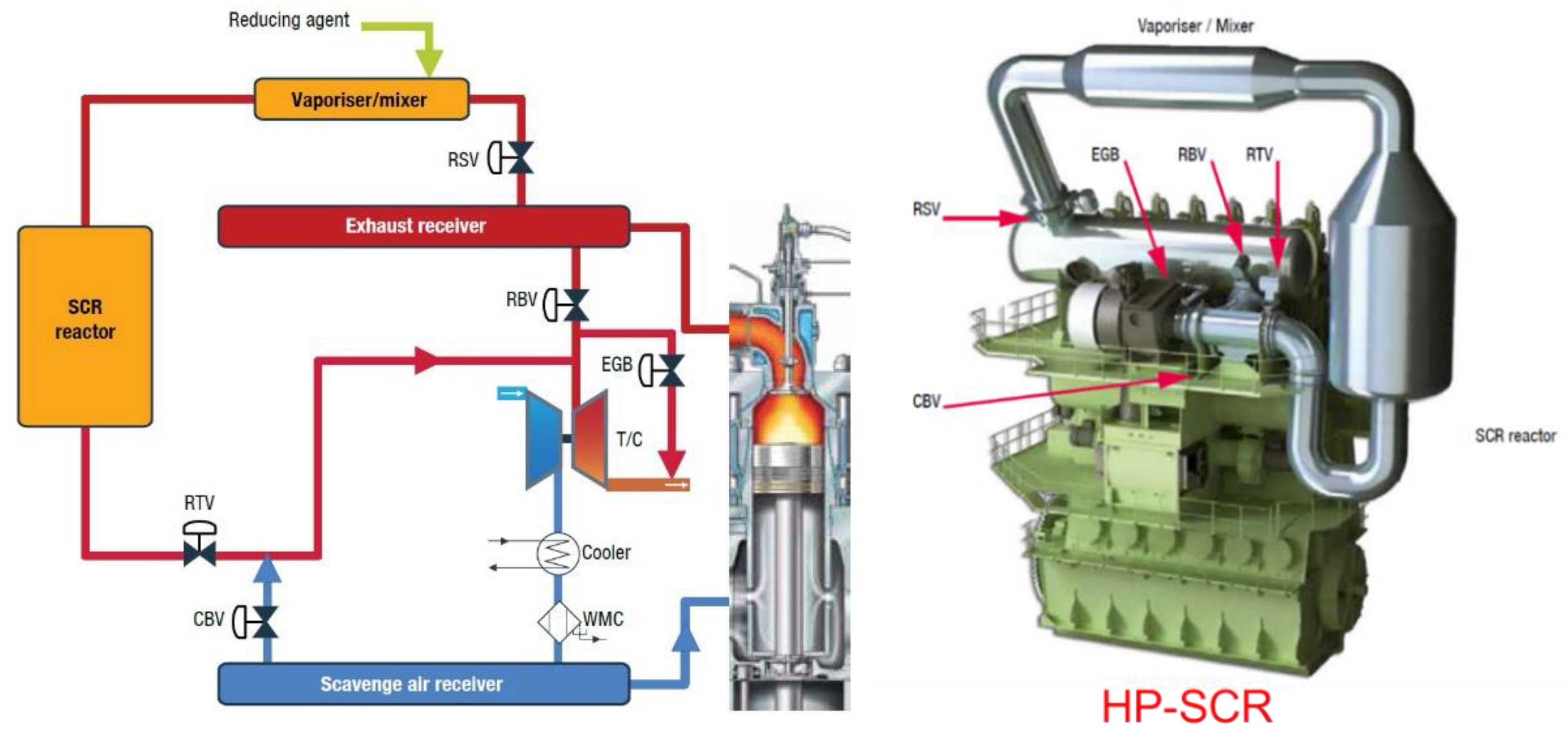
2.1. High-Pressure SCR System

The HP-SCR system is mainly installed before the diesel turbocharger to fully increase the SCR reaction temperature [24]. This SCR system has a compact layout and high exhaust gas energy utilization rate, but it has a large impact on the working performance of diesel engines and turbochargers [25]. It is mainly used in two-stroke low-speed diesel engines burning high sulfur heavy oil.
Figure 2 shows the HP-SCR system developed by MAN, which mainly includes four parts: vaporizer/mixer, SCR reactor, auxiliary fan, and bypass valve group. The vaporizer/mixer mainly guarantees the complete evaporation and decomposition of the injected urea solution, and ensures the uniform mixing of the reducing agent NH3 and the exhaust gas. Exhaust gas in the exhaust pipe drives the turbocharger to work, and the exhaust gas temperature before and after the turbocharger differs by 50–175 °C [26]. Therefore, the SCR system in front of the turbocharger can make full use of the higher exhaust gas temperature (low pressure 500 °C) to increase the SCR system denitration efficiency [27].
Figure 3 shows the relationship between the exhaust gas temperature before the turbine and the minimum operating temperature required by the SCR system. It can be seen that when the main engine is running at low load, the temperature of the exhaust gas before the turbine is low and cannot reach the normal working temperature required by the SCR system.
In the HP-SCR system, the bypass valve group mainly includes a reactor sealing valve (RSV), a reactor throttle valve (RTV), a reactor bypass valve (RBV), an exhaust gas bypass valve (EGB), and a cylinder bypass valve (CBV). The combination of five groups of pneumatic valves controls whether the exhaust gas flows through the SCR reactor, that is, whether the exhaust gas is treated. For diesel engines that meet the IMO Tier II standard, the switch of the bypass valve group determines the working mode of the diesel engine—Tier II mode or Tier III mode [28]. Additionally, the two working modes of the diesel engine also meet the different emission standards.
In diesel Tier II mode, the RBV is opened, the RSV and the RTV are closed, the exhaust gas directly enters the turbocharger, and the SCR system is inoperative [29,30,31]. At this time, whether the EGB is opened depends on whether the NOx emissions of the diesel engine meet the IMO Tier II standard. Generally, the diesel engine produces heavy pollutants at low load, and the EGB ensures that the NOx emissions of the diesel engine meet the IMO Tier II standard [32]. In contrast, in diesel Tier III mode, the RSV and RTV are opened, the RBV is closed, and the exhaust gas flows through the vaporizer/mixer and SCR reactor and then enters turbocharger, so the SCR system is working.
The exhaust gas temperature often cannot meet the working requirements of the SCR system under low load of diesel engine, even if the SCR system is arranged in front of the turbocharger [33]. To solve such problems, a CBV is arranged between the scavenging collector and the turbocharger inlet to control the amount of fresh air entering the cylinder. When the CBV is opened, part of the fresh air will flow into the exhaust pipe, and the amount of fresh air entering the cylinder will be reduced, but the scavenging pressure will remain unchanged [34,35,36]. When the fuel consumption increases, the exhaust temperature of the diesel engine will inevitably increase, and the degree of its increase depends on the increase in fuel consumption [37]. Figure 4 shows the control chart of the bypass valve group.
In diesel Tier III mode, the existence of the vaporizer/mixer and SCR reactor causes a thermal delay between the exhaust gas manifold and the turbocharger [38]. Additionally, the degree of thermal delay mainly depends on the size of the SCR reactor and the heat capacity of the catalyst. This thermal delay will inevitably affect the working performance of diesel engines and turbochargers [39]. The auxiliary fans need to be introduced to ensure the stability of the exhaust pipe [40].

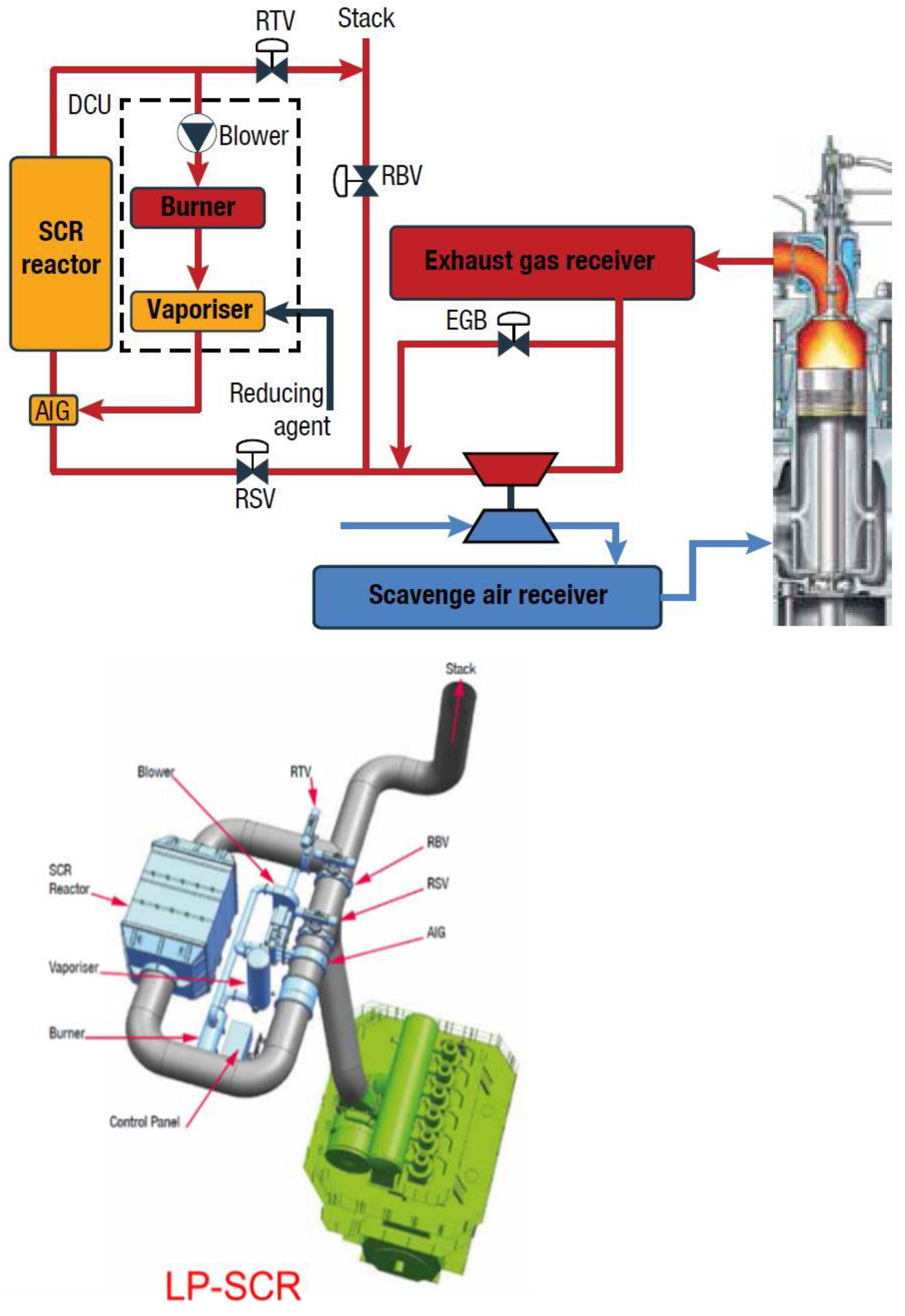
2.2. Low-Pressure SCR System

Compared with the HP-SCR system, the LP-SCR system arranged behind the turbocharger has high adaptability and has less impact on diesel engines and turbochargers [41]. It has been widely used in medium and high speed diesel engines [42,43]. For low-speed two-stroke diesel engines, the denitration efficiency of the LP-SCR system is limited due to its low exhaust temperature [44]. Generally, in the exhaust system of low-speed diesel engines, that is, after the turbocharger and before the SCR reactor, an exhaust gas heating device is installed to increase the exhaust temperature of the diesel engine [45]. At present, there are two commonly used heating methods: electric heating and fuel injection in the exhaust pipe for re-ignition [46,47]. Both heating methods have their advantages, but their equivalent increase in fuel consumption should be controlled within 2.0 g/(kW·h).
Figure 5 shows the LP-SCR system developed by Doosan Corporation, which mainly includes four parts: static mixer (ammonia spray grid), SCR reactor, decomposition unit and bypass valve group. The decomposition unit is connected to the outlet of the SCR reactor and the inlet of the static mixer, and it includes auxiliary fan, exhaust gas heating device (burner) and evaporator [48]. Liquid ammonia or ammonia water is sprayed into the evaporator and mixed with the exhaust gas from blower into the SCR reactor [49].
In the LP-SCR system, the bypass valve group mainly includes a reactor sealing valve (RSV), a reactor throttle valve (RTV), and an exhaust gas bypass valve (EGB). The combination of three pneumatic valves controls whether the exhaust gas flows through the SCR reactor, or whether the exhaust gas is treated. Similar to the HP-SCR system, the diesel engine matching the LP-SCR system also has two working modes—Tier II mode and Tier III mode [50,51].
The exhaust gas temperature after the turbine cannot meet the working requirements of the SCR system under the low load of the diesel engine, even if using the low sulfur fuel. To solve such problems, the CBV is placed between the exhaust manifold outlet and the turbocharger outlet to control the amount of fresh air entering the cylinder. When the CBV is opened, part of the exhaust gas on the high pressure side of the turbine will directly flow into the low pressure side of the turbine, the scavenging pressure will be reduced, and the amount of fresh air entering the cylinder will be reduced. With the increase in fuel consumption, the temperature of diesel exhaust gas will inevitably increase, and the degree of its increase depends on the increase in the fuel consumption. Even if the diesel engine uses low sulfur fuel, the formation of ammonium bisulfate or ammonium bisulfite cannot be completely avoided, but the arrangement of the decomposition unit can alleviate such problems [52].

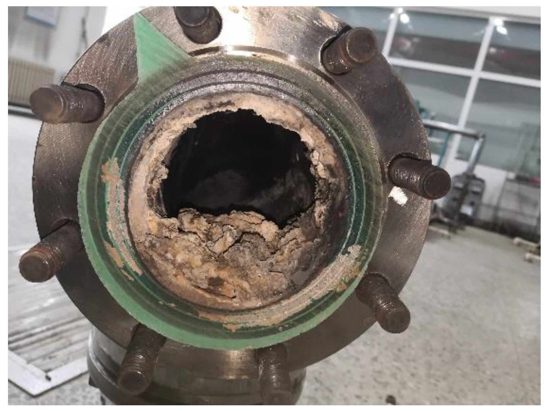
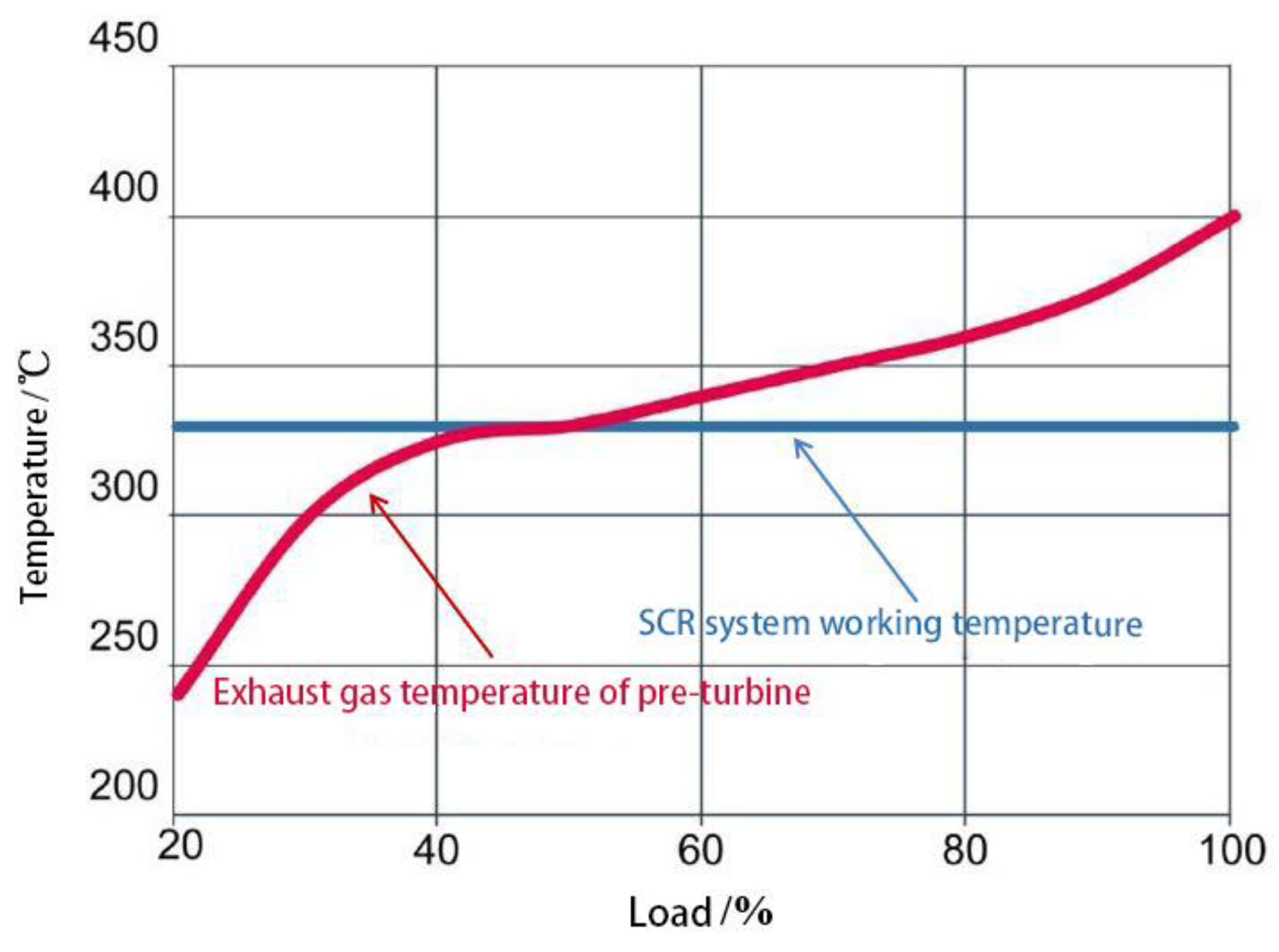
3. Application Problems of Marine Low-Speed Diesel Engines

Based on the ship operating cost, low-speed marine diesel engines generally burn the inferior residual oil [53]. However, the inferior residual oil often has the characteristics of high viscosity, high sulfur content, high residual carbon, and heavy metals (cadmium, vanadium, lead, etc.), and its exhaust gas must contain a lot of pollutants such as SOx (SO2 and SO3) and particulate matter (including oil stain). Due to the SO3 and H2O in the exhaust gas, the sulfuric acid vapor (H2SO4) is easily generated at lower temperatures [54]. When the fuel contains more sulfur, the following three reactions will occur under appropriate conditions:
(1) Fuel burning:
S + O 2 SO 2
(2) Exhaust gas cooling temperature range of 200–560 °C:
2 SO 2 + O 2 2 SO 3
(3) Reaction with water:
SO 3 + H 2 O H 2 SO 4
At the same time, as the vanadium-based catalyst (active ingredient: V2O5) promotes the oxidation of SO2 to SO3, the concentration of sulfuric acid vapor at the outlet of the SCR reactor is further increased. When the SCR system stops working, or its operating temperature drops below the acid dew point temperature, the sulfuric acid vapor will cool and condense on the exhaust pipe or the reactor wall [55,56]. If it is not discharged in time, long-term accumulation will cause corrosion of the pipeline as shown in Figure 6.
During the normal operation of the SCR system, due to the introduction of urea solution, the generated ammonia gas and sulfuric acid vapor will condense into ammonium bisulfate and other substances as shown in Equation (8), causing the amount of sulfuric acid vapor before and after the reactor to be lower [57].
NH 3 + H 2 SO 4 NH 4 HSO 4
However, the sulfate produced will block the surface structure or pores of the catalyst, resulting in a decrease in catalyst activity. This process is reversible; when the temperature of the exhaust gas rises above the acid dew point, the ammonium bisulfate will decompose and the catalyst activity will be restored [58]. However, if the operating temperature is lower than its acid dew point for a long time, the catalyst activity will permanently change, which will deactivate the catalyst, as shown in Figure 7 [28,59].
The acid dew point temperature of the ammonium bisulfate is usually 280–320 °C, but the low-speed diesel engine has higher thermal efficiency (up to 50%), which results in the lower temperature of its exhaust gas, and the exhaust gas temperature will be lower than the acid dew point temperature of ammonia bisulfate under some operating loads [60]. Therefore, on one hand, it will aggravate the formation of ammonium bisulfate [61]. On the other hand, it will cause the incomplete decomposition of urea at low temperatures and precipitate crystals on the inner wall surface of the pipeline as shown in Figure 8 [62,63].
From the perspective of diesel engine operation, using the engine tuning method to increase the diesel exhaust temperature [64], this method will increase the minimum operating temperature of the SCR system or catalyst, which can avoid the formation of sulfate and other deposits. At present, the engine tuning methods mainly include CBV and the turbine EGB [65,66]. By reducing the amount of fresh air entering the combustion chamber and increasing the amount of fuel injected, the exhaust gas temperature is increased at the expense of some fuel economy [67]. Although both methods or means can increase the exhaust gas temperature, it will decrease the power output and fuel economy of the engine, as well as bring about the problem of the turbine matching with the engine [68].
In particular, when the operating loads of the diesel engine change (such as rapid loading or unloading), there may be short-term differences or delays in the exhaust gas temperature before and after the reactor (between the exhaust gas header outlet and the turbine inlet) due to the large thermal inertia of the SCR system catalyst [69]. It will cause energy imbalance before and after the turbine and affect the normal operation of the turbine. Of course, the degree of this thermal delay mainly depends on the size of the SCR reactor and the heat capacity of the catalyst [70,71].

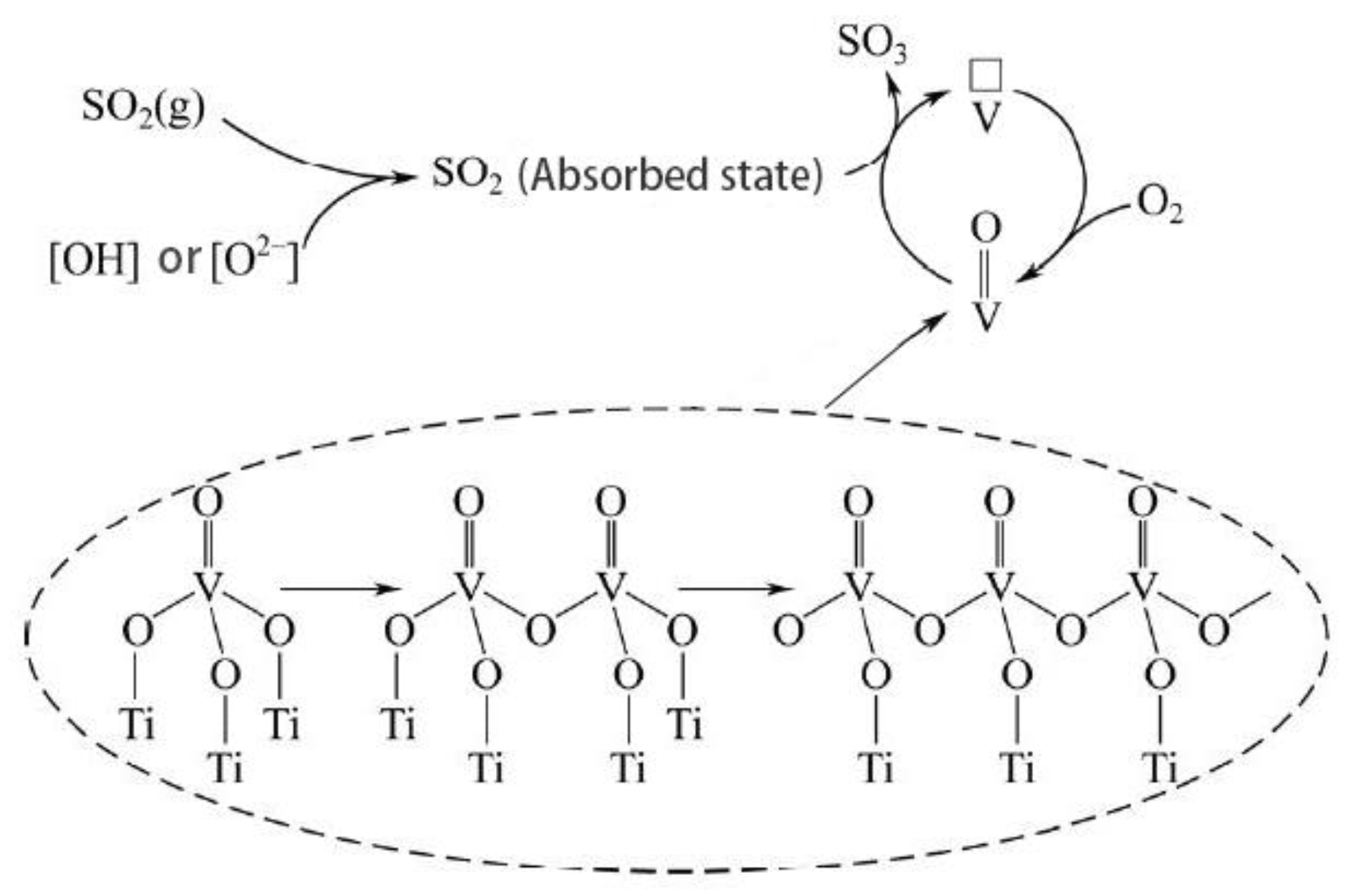
4. Research on Catalytic Reaction Mechanism under the High Sulfur Exhaust Gas Condition

Marine diesel engine SCR systems usually use honeycomb or plate vanadium-based catalysts, and SCR reactions are a gas–solid heterogeneous reaction that occurs on the catalyst surface [72]. Generally, the SCR reaction process includes standard SCR reaction, fast SCR reaction, slow SCR reaction and its side reactions [73].
Standard SCR reaction:
4 NH 3 + 4 NO + O 2 4 N 2 + 6 H 2 O
Fast SCR reaction:
4 NH 3 + 2 NO + 2 NO 2 4 N 2 + 6 H 2 O
Slow SCR reaction:
8 NH 3 + 6 NO 2 7 N 2 + 12 H 2 O
When the exhaust gas temperature of the marine diesel engine is high, the by-product N2O is generated, and part of NH3 is oxidized in the SCR reaction. The related side reactions are:
2 NO 2 + 2 NH 3 N 2 O + N 2 + 3 H 2 O
4 NO + 4 NH 3 + 3 O 2 4 N 2 O + 6 H 2 O
4 NH 3 + 5 O 2 4 NO + 6 H 2 O
4 NH 3 + 3 O 2 2 N 2 + 6 H 2 O
When the exhaust gas temperature of the marine diesel engine is low, the catalyst will have some side reactions that will mainly include the formation reaction of ammonium salts such as sulfate and nitrate [74,75]. The related side reactions are:
2 NH 3 + 2 NO 2 NH 4 NO 3 + N 2 + H 2 O
NH 3 + SO 2 + H 2 O NH 4 HSO 3
NH 3 + SO 3 + H 2 O NH 4 HSO 4
Only when the reaction temperature is higher than 350 °C, reaction (14) and (15) may occur, and the reactions will be more violent when the temperature is higher than 450 °C. When the exhaust gas temperature of the marine diesel engine is lower than 250 °C and contains a large amount of NO2, the reaction as shown in Equation (16) will occur [76].
The exhaust gas of diesel engine contains a large amount of NO due to the oxygen-rich combustion. Therefore, the denitration efficiency of the SCR system is mainly limited by the standard SCR reaction and the fast SCR reaction [77]. As the SCR side reactions occur under the harsh conditions and are relatively insignificant in magnitude, the effects of its side reactions are ignored [78]. Based on this characteristic, the denitration mechanism mainly depends on the standard SCR reaction and the fast SCR reaction, and it is believed that it follows the Eley–Rideal mechanism or the Langmuir–Hinshelwood mechanism [79,80,81]. The denitration reaction mechanism based on the standard SCR reaction path proposed by Topsoe laboratory is shown in Figure 9.
The study found that this reactor mechanism or model can predict the progress of SCR reactions in automotive SCR systems or marine LP-SCR systems, but the prediction accuracy is poor for low-speed marine diesel engines under high sulfur fuel and low temperature exhaust [82].
Considering that the marine diesel engine uses inferior fuel, the exhaust gas temperature is low (up to 200 °C or lower), and the SOx concentration in the exhaust gas is higher (up to 700 ppm or higher) [83], so the operating temperature range of the SCR system will inevitably be within the acid dew point of the ammonium salt, and the products of sulfates and nitrates will limit its denitration performance. At present, the study of catalysts and catalytic mechanisms is less common under marine diesel engine exhaust conditions [84], but studies on heavy metal poisoning [85] and the sulfur poisoning [86,87] of catalyst samples have been ongoing under laboratory conditions. Therefore, catalyst sulfur poisoning or passivation can be divided into two types [88]: first, the gas-phase SOx and the catalysts or the heavy metals in the exhaust gas form stable substances [89]; second, the gas-phase SOx and NH3 in the exhaust gas generate ammonium salt substances that are easily decomposed at high temperatures [90]. The difference is that the former is irreversible (catalyst deactivation) and the latter is reversible (active passivation).
These easily form sulfates and nitrates with NH3 at low temperatures, because SOx and NOx are both acid gases [91]. In addition, the exhaust temperature of marine diesel engines is low and the composition of exhaust gas is complicated [92]. When there is a large amount of SOx and H2O in the exhaust gas, the formation reactions of ammonium salts will occur, and the ammonium salts will block the catalyst surface and pores [93,94] and greatly reduce the activity of marine SCR catalysts [95]. These ammonium salts mainly include ammonium sulfate ((NH4)2SO4), ammonium bisulfate (NH4HSO4), ammonium sulfite ((NH4)2SO3), ammonium bisulfite (NH4HSO3), ammonium nitrate (NH4NO3), etc. [96], and their properties are relatively unstable and easily decomposed at high temperatures. In other words, when such ammonium salts have formed, the catalyst activity can be restored after high temperature treatment. Therefore, such reactions can be called catalyst ammonium salt passivation reactions [97].
For sulfates, the acid dew point temperature of ammonium bisulfate is usually 280–320 °C, the formation of ammonium bisulfate limits the minimum operating temperature of the SCR catalysts [98,99]. When the temperature is lower than the acid dew point, ammonia gas and sulfuric acid vapor will condense into ammonium bisulfate and block the surface structure of the catalyst [100]. The reaction process is reversible, when the operating temperature rises above the dew point, the ammonium bisulfate will evaporate and the catalyst activity will be restored [101]. However, the catalyst activity will change permanently if the operating temperature is lower than its dew point for a long time, which means the catalyst will be deactivated [102]. At the same time, V2O5 in the vanadium-based catalyst will promote the oxidation of SO2 to SO3 in the exhaust gas (Figure 10), which will aggravate the formation of ammonium sulfate [103].
Different from ammonium sulfate, the effects of ammonium nitrate are mainly reflected in, first, inhibiting the formation of intermediate products (NH4NO2) in the fast SCR reaction path [104,105], and second, blocking the surface structure of the catalyst. Nevertheless, nitrate is easier to decompose than sulfate, and it can decompose at 170 °C [106]. Therefore, low temperature is an important reason for the formation of ammonium nitrate sediments.

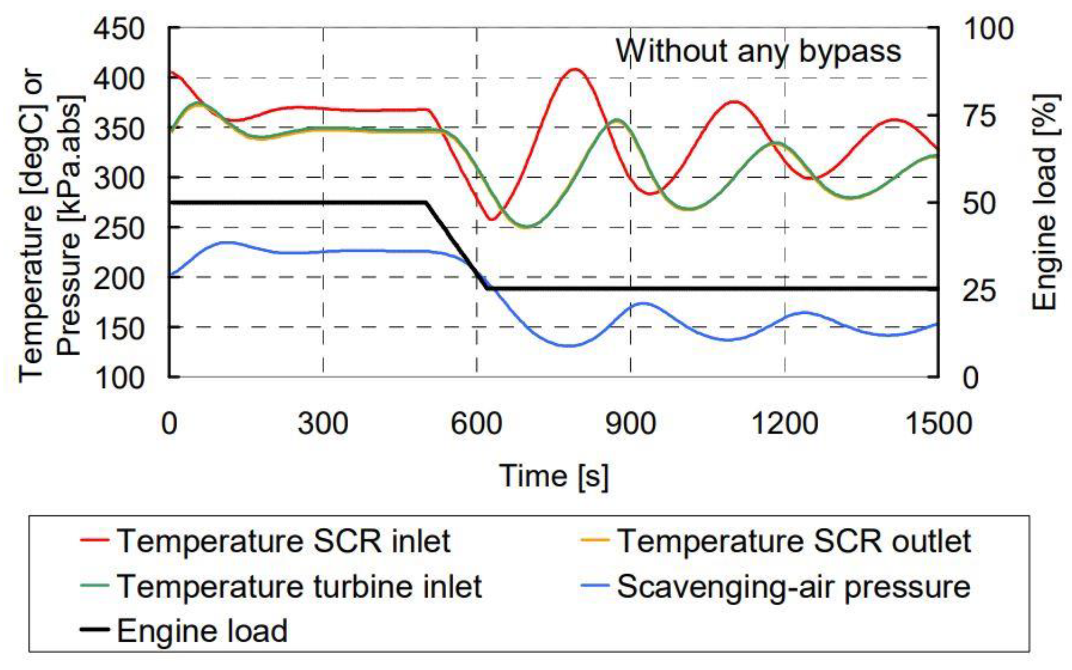
5. Research on Engine Tuning and Control Strategy under Variable Operating Conditions

The exhaust gas states of marine low-speed diesel engines cannot directly meet the SCR working requirements due to the low temperature and complex composition of the exhaust gas [107], which strongly limits the denitration efficiency of the marine SCR systems [108]. The marine diesel SCR system, especially the two-stroke low-speed diesel SCR system [109], must rely on different engine tuning technologies to increase the temperature of its exhaust gas to obtain the higher denitration efficiency [110,111,112].
The engine tuning process of the low-speed diesel engine is shown in Figure 11. During its operation, the pneumatic valves are used to control whether the exhaust gas flows through the SCR reactor or whether the exhaust gas has been treated [113]. For the diesel engines that meet the IMO Tier II standard [114], the switch of the bypass valves determines the working mode of the diesel engine—Tier II mode or Tier III mode [115], and the two working modes of the diesel engine also meet different emission standards [116]. The marine diesel SCR system uses a discontinuous operation mode due to the differences of emission regulations in different sea areas [117]. The cold wall surface and the catalyst windward side are easily blocked by crystals under non-continuous operation conditions, which causes the consumption and waste of a large amount of reducing agent [118,119].
When the low-speed marine diesel engine burns the inferior high sulfur fuel, a large amount of gas-phase SOx will inevitably exist in its exhaust gas [120]. In this case, it is necessary to confirm the minimum operating temperature of the SCR system or denitration catalyst to avoid the formation of sulfate and other deposits [121]. Generally, the operating temperature of the high-pressure SCR system is required to be higher than 320 °C to avoid the generation of sulfate and nitrate under the high sulfur exhaust gas conditions (fuel sulfur content 3.5%) [122,123]. For marine diesel engines, the exhaust gas temperature before the turbine can only meet this requirement under some operating conditions [124]. In particular, though the marine low-speed diesel engines have higher thermal efficiency, the exhaust gas temperature before the turbine is difficult to meet this requirement under most working conditions [125]. When the load of the diesel engine is below 15% MCR, the injection of urea solution must be stopped to prevent the formation of large amounts of deposits at low temperatures [126].
At present, the common engine tuning methods mainly include CBV and turbine EGB [127,128]. By reducing the quantity of the fresh air entering the combustion chamber and increasing the amount of fuel injected [129], the exhaust gas temperature is increased at the expense of the fuel economy [130]. Both technologies can increase the exhaust gas temperature, but it will decrease the main engine power output [131] and fuel economy [132], it will also bring the matching problems between the main engine and the turbine [133,134,135]. The change trends of exhaust gas temperature and pressure before the turbine during variable operating conditions are shown in Figure 12 [136].
In addition, when the operating conditions of the diesel engine change, there may be short-term differences or delays in the exhaust gas temperature before and after the reactor (between the exhaust gas header outlet and the turbine inlet) due to the thermal inertia of the SCR system catalyst [137]. It will cause the energy imbalance before and after the turbine and affect the normal operation of the turbine. Michael I. Foteinos et al. [138] showed the inlet and outlet temperature change of high-pressure SCR reactor during the main engine acceleration and deceleration, and the maximum temperature difference exceeds 100 °C. Of course, the degree and duration of the thermal delay mainly depends on the size of the SCR reactor and the heat capacity of the catalyst [139], but the low-speed diesel SCR system has a relatively large volume, and this thermal inertia has a greater impact on the transient performance [140].

6. Conclusions

(1) The HP-SCR system arranged in front of the turbine can make full use of the higher exhaust gas temperature and improve the catalyst activity. At the same time, the HP-SCR system has a higher working pressure, and its absolute pressure is much higher than that of the LP-SCR system, which is equivalent to reducing the volume flow rate or the linear velocity of the exhaust gas and increasing the SCR reaction time. Under the same design requirements, the HP-SCR system has the more compact structure and the higher energy efficiency, and it is more suitable for low-speed diesel engines with large power.
(2) The study of the SCR reaction mechanism under the limit conditions of high pressure and high sulfur is an important theoretical basis for solving the practical application problems of low-speed diesel engines. Low temperature is an important reason for the formation of ammonium nitrate, ammonium sulfate, and other deposits. Additionally, the formed deposits will directly affect the working performance of the SCR systems. The passivation mechanism of the ammonium salt under the high sulfur exhaust gas is an important basis for determining the operating requirements of the HP-SCR system. Additionally, the passivation mechanism of the ammonium salt must consider the effects of sulfate and nitrate comprehensively.
(3) To solve the problem of the practical application of the HP-SCR system, it is of great significance to construct the model for predicting the transient performance of the marine low-speed diesel HP-SCR system and study the engine tuning method or cooperative control strategy under variable operating conditions. Under the condition of low sulfur exhaust gas, the emission reduction effect of the SCR system can meet the Tier III requirements, while under the high sulfur emissions it struggles to meet the requirements of Tier III regulations. Therefore, when the low-speed diesel engines burn high sulfur heavy oil, it is necessary to take relevant engine tuning measures.
(4) At present, SCR technology is the most mature and effective technology to deal with nitrogen oxide emissions and has been widely used in the shipbuilding industry. In the future, the emission standards of nitrogen oxides will become more and more stringent, and it is of great significance to study more efficient denitration technologies. At the same time, due to the development of marine energy-saving technologies, the thermal efficiency of low-speed diesel engine is continuously improved, which makes its exhaust temperature drop constantly. Under the dual restrictions of high sulfur fuel and low exhaust temperature, the low-speed diesel engine SCR systems will inevitably sacrifice part of the engine economy to obtain higher denitrification efficiency and operational reliability. For HP-SCR products, it will develop in the direction of miniaturization, integration, and high efficiency, and may be integrated on the engine in future development. For LP-SCR products, it will focus on low-temperature catalyst research and urea decomposition efficiency to improve the denitration efficiency and service life of the LP-SCR system.

Author Contributions

Conceptualization, Y.Z. and W.Z.; Funding acquisition, Y.Z.; Project administration, Y.Z.; Software, W.Z. and C.X.; Writing—original draft preparation, Y.Z. and W.Z.; Writing—review and editing, W.Z. and Q.H. All authors have read and agreed to the published version of the manuscript.

Funding

We gratefully acknowledge the financial support of the National Natural Science Foundation of China (No. 51979060).

Conflicts of Interest

The authors declare no conflict of interest.

Abbreviations

CBVCylinder Bypass Valve
COCarbon monoxide
CO2Carbon dioxide
DEFDiesel Exhaust Fluid
DPFDiesel Particulate Filter
ECAEmission Control Areas
EGBExhaust Gas Bypass Valve
EGRExhaust Gas Recirculation
HCsHydrocarbons
HFOHeavy Fuel Oil
HP-SCRHigh-Pressure SCR
H2SO4Sulfuric acid vapor
IFOIntermediate Fuel Oil
IMOInternational Maritime Organization
LP-SCRLow-Pressure SCR
MCRMaximum Continuous Rating
MDOMarine Diesel Oil
NH3Ammonia
NH4HSO3Ammonium bisulfite
NH4HSO4Ammonium bisulfate
NH4NO3Ammonium nitrate
(NH4)2SO3Ammonium sulfite
(NH4)2SO4Ammonium sulfate
NOxNitrogen Oxides
PMParticulate Matter
RBVReactor Bypass Valve
ROResidual Oil
RSVReactor Sealing Valve
RTVReactor Throttle Valve
SCRSelective Catalytic Reduction
SO2Sulfur dioxide
SOxSulphur Oxides
UFPUltrafine Particles
UWSUrea-Water Solution
VOCVolatile Organic Compounds

References

  1. International Maritime Organization (IMO). List of Special Areas, Emission Control Areas and Particularly Sensitive Sea Areas; MEPC.1/Circ.778/Rev.3; International Maritime Organization: London, UK, 2018. [Google Scholar]
  2. Parthasarathy, M.; Ramkumar, S.; Elumalai, P.V.; Murugu Nachippan, N.; Dhinesh, B. Control Strategies on HCCI Engine Performance and Emission characteristics by Combined Effect of Exhaust Gas Recirculation with Blend of Biodiesel and N-Heptane. Energy Sources Part A Recovery Util. Environ. Eff. 2020. [Google Scholar] [CrossRef]
  3. Ministry of Transport of the People’s Republic of China. Implementation Plan of the Ship Air Pollutant Emission Control Areas; Ministry of Transport of the People’s Republic of China: Beijing, China, 2018.
  4. Wang, Y.; Ge, D.; Che, M.; Gao, S.; Wu, Z. A dual-functional way for regenerating NH3-SCR catalysts while enhancing their poisoning resistance. Catal. Commun. 2018, 117, 69–73. [Google Scholar] [CrossRef]
  5. Yusuf, A.A.; Yusuf, D.A.; Jie, Z.; Bello, T.Y.; Tambaya, M.; Abdullahi, B.; Muhammed-Dabo, I.A.; Yahuza, I.; Dandakouta, H. Influence of waste oil-biodiesel on toxic pollutants from marine engine coupled with emission reduction measures at various loads. Atmos. Pollut. Res. 2022, 13, 101258. [Google Scholar] [CrossRef]
  6. Yusuf, A.A.; Inambao, F.L.; Ampah, J.D. Evaluation of biodiesel on speciated PM2.5, organic compound, ultrafine particle and gaseous emissions from a low-speed EPA Tier II marine diesel engine coupled with DPF, DEP and SCR filter at various loads. Energy 2022, 239, 121837. [Google Scholar] [CrossRef]
  7. Ni, P.; Wang, X.; Li, H. A review on regulations, current status, effects and reduction strategies of emissions for marine diesel engines. Fuel 2020, 279, 118477. [Google Scholar] [CrossRef]
  8. Feng, Y.; Du, Z.; Shreka, M.; Zhu, Y.; Zhou, S.; Zhang, W. Thermodynamic analysis and performance optimization of the supercritical carbon dioxide Brayton cycle combined with the Kalina cycle for waste heat recovery from a marine low-speed diesel engine. Energy Convers. Manag. 2020, 206, 112483. [Google Scholar] [CrossRef]
  9. Wartsila Company. Wartsila Environmental Product Guide; Wartsila Company Press: Helsinki, Finland, 2017. [Google Scholar]
  10. Dirk, K.; Martin, B.; Severin, Z.; Flavio, S. Compact Marine High-Pressure SCR System Technology Development. In Proceedings of the CIMAC Congress, Vancouver, BC, Canada, 10–14 June 2019. [Google Scholar]
  11. Kaźmierski, B.; Górka, K.; Kapusta, Ł.J. A conceptual design and numerical analysis of the mixerless urea-SCR system. Combust. Engines 2021, 187, 12–20. [Google Scholar] [CrossRef]
  12. Prabhu, S.S.; Natesan, K.; Shivappa Nayak, N. Effect of UWS spray angle and positioning of injector on ammonia concentration in Urea-SCR system. Mater. Today Proc. 2021, 46, 8051–8055. [Google Scholar] [CrossRef]
  13. Cho, Y.S.; Lee, S.W.; Choi, W.C.; Yoon, Y.B. Urea-SCR system optimization with various combinations of mixer types and decomposition pipe lengths. Int. J. Automot. Technol. 2014, 15, 723–731. [Google Scholar] [CrossRef]
  14. Tischer, S.; Börnhorst, M.; Amsler, J.; Schoch, G.; Deutschmann, O. Thermodynamics and reaction mechanism of urea decomposition. Phys. Chem. Chem. Phys. 2019, 21, 16785–16797. [Google Scholar] [CrossRef] [PubMed] [Green Version]
  15. Huang, H.; Chen, Y.; Li, Z.; Wang, H.; Hao, B.; Chen, Y.; Lei, H.; Guo, X. Analysis of deposit formation mechanism and structure optimization in urea-SCR system of diesel engine. Fuel 2020, 265, 116941. [Google Scholar] [CrossRef]
  16. Yu, J.; Mo, C.; Huang, W.; Duan, L.; Long, H.; Mo, Y. Detailed Reaction Pathways of Urea Deposit in Diesel Engine with Selective Catalytic Reduction System. Trans. CSICE 2020, 38, 169–177. [Google Scholar]
  17. Qian, F.; Lv, L.; Yang, D. Simulation of Deposit Formation Inside the Exhaust Pipe on a Diesel Engine with SCR. Trans. CSICE 2018, 36, 144–152. [Google Scholar]
  18. MAN B&W. MAN Emission Project Guide: MAN B&W Two-Stroke Marine Engines; MAN B&W Press: Augsburg, Germany, 2019. [Google Scholar]
  19. Ryu, C.; Hwang, J.; Cheon, J. The world’s first commercialized low pressure SCR system on 2-stroke engine DeNOx system. In Proceedings of the Helsinki: 28th CIMAC Congress, Helsinki, Finland, 6–10 June 2016. No. 305. [Google Scholar]
  20. Han, L.; Cai, S.; Gao, M.; Hasegawa, J.Y.; Wang, P.; Zhang, J.; Shi, L.; Zhang, D. Selective Catalytic Reduction of NOx with NH3 by Using Novel Catalysts: State of the Art and Future Prospects. Chem. Rev. 2019, 119, 10916–10976. [Google Scholar] [CrossRef]
  21. Li, M.; Zhang, Y.; Liu, X.; Zhang, Q.; Li, Z. Numerical investigation on the urea deposit formation process in a selective catalytic reduction system of a diesel engine based on a fluid–solid coupling method. ACS Omega 2021, 6, 5921–5932. [Google Scholar] [CrossRef]
  22. Tan, L.; Feng, P.; Yang, S.; Guo, Y.; Liu, S.; Li, Z. CFD studies on effects of SCR mixers on the performance of urea conversion and mixing of the reducing agent. Chem. Eng. Process. 2018, 123, 82–88. [Google Scholar] [CrossRef]
  23. Christensen, H. Tier III SCR for large 2-stroke MAN B&W diesel engines. In Proceedings of the International Symposium on Marine Engineering, Kobe, Japan, 17–21 October 2011. [Google Scholar]
  24. Zhu, Y.; Li, T.; Xia, C.; Feng, Y.; Zhou, S. Simulation analysis on vaporizer/mixer performance of the high-pressure SCR system in a marine diesel. Chem. Eng. Process. 2020, 148, 107819. [Google Scholar] [CrossRef]
  25. Han, B.; Shen, Y.; Zhu, S.; Liu, Y.; Shen, S. Promotional effect of phosphorylation on CeSn0.8W0.6Ox/TiAl0.2Si0.1Oy for NH3-SCR of NO from marine diesel exhaust. J. Rare Earths 2016, 34, 1010–1016. [Google Scholar] [CrossRef]
  26. Börnhorst, M.; Deutschmann, O. Advances and challenges of ammonia delivery by urea-water sprays in SCR systems. Prog. Energ. Combust. 2021, 87, 100949. [Google Scholar] [CrossRef]
  27. Cimino, S.; Lisi, L.; Tortorelli, M. Low temperature SCR on supported MnOx catalysts for marine exhaust gas cleaning: Effect of KCl poisoning. Chem. Eng. J. 2016, 283, 223–230. [Google Scholar] [CrossRef]
  28. Murakami, M.; Nakao, T. Test Results of Marine SCR System for Large Diesel Engines during Long Term Service Test. J. JIME 2015, 50, AP3. [Google Scholar] [CrossRef]
  29. Xiao, L.; Lyu, L.; Zhu, N. Research and Application on the Structural Design of SCR Catalystin Marine Diesel Engine. Intern. Combust. Engines 2019, 4, 1–6. [Google Scholar]
  30. Yang, Z.; Jiang, G.; Zhang, X.; Wei, H. Application of selective reduction catalyst to marine diesel engine. J. Harbin Eng. Univ. 2017, 38, 1539–1544. [Google Scholar]
  31. Liang, R. Quantum Chemistry Research on DeNOX and Poisoning Mechanism of SCR Catalyst. Master’s Thesis, North China Electric Power University, Beijing, China, 2017. [Google Scholar]
  32. Qu, J.; Feng, Y.; Xu, G.; Zhang, M.; Zhu, Y.; Zhou, S. Design and thermodynamics analysis of marine dual fuel low speed engine with methane reforming integrated high pressure exhaust gas recirculation system. Fuel 2022, 319, 123747. [Google Scholar] [CrossRef]
  33. Wang, Z.; Zhu, Y.; Zhou, S.; Feng, Y. Reaction mechanism and chemical kinetics of NH3-NO/NO2-SCR system with vanadium-based catalyst under marine diesel exhaust conditions. Proc. Inst. Mech. Eng. Part A J. Power Energy 2020, 234, 342–352. [Google Scholar] [CrossRef]
  34. Zhang, L. The Injecting Structural Parameters Optimization and Matching Performance of SCR System for Marine Diesel Engine. Master’s Thesis, Jimei University, Xiamen, China, 2016. [Google Scholar]
  35. Ji, P. Research of SO2 Oxidation over SCR Catalyst and Regulatory Mechanism. Master’s Thesis, Zhejiang University, Hangzhou, China, 2016. [Google Scholar]
  36. Clair, S.; de Oteyza, D.G. Controlling a Chemical Coupling Reaction on a Surface: Tools and Strategies for On-Surface Synthesis. Chem. Rev. 2019, 119, 4717–4776. [Google Scholar] [CrossRef]
  37. Qu, J.; Feng, Y.; Zhu, Y.; Zhou, S.; Zhang, W. Design and thermodynamic analysis of a combined system including steam Rankine cycle, organic Rankine cycle, and power turbine for marine low-speed diesel engine waste heat recovery. Energy Convers. Manag. 2021, 245, 114580. [Google Scholar] [CrossRef]
  38. Peng, H.; Chen, W. The analysis and countermeasures of the system problems in SCR flue gas denitrification ammonia zone. Green Pet. Petrochem. 2019, 4, 45–48. [Google Scholar]
  39. Ou, S.; Min, E.; Zhang, L.; Deng, Z.; Yin, Z. Experimental Analysis on Matching Performance of SCR System for a Marine Diesel Engine. Ship Eng. 2017, 39, 66–70. [Google Scholar]
  40. Zheng, C. Numerical Simulation and Test Verification of the whole Process of SCR System for Marine Low Speed Diesel Engine. Master’s Thesis, China Ship Research Institute, Beijing, China, 2019. [Google Scholar]
  41. Gao, C.; Shi, J.; Fan, Z.; Wang, B.; Wang, Y.; He, C.; Wang, X.; Li, J.; Niu, C. “Fast SCR” reaction over Sm-modified MnOx–TiO2 for promoting reduction of NOx with NH3. Appl. Catal. A Gen. 2018, 564, 102–112. [Google Scholar] [CrossRef]
  42. Xie, P.; Gao, M.; Zhang, H.; Niu, Y.; Wang, X. Dynamic modeling for NOx emission sequence prediction of SCR system outlet based on sequence to sequence long short-term memory network. Energy 2020, 190, 116482. [Google Scholar] [CrossRef]
  43. Liu, G.; Cui, Y.; Ji, J.; Shen, D.; Wang, Q.; Li, C.; Luo, K. A technical method to improve NOx/NH3 mixing ratio in CR systemand its engineering applications. J. Energy Inst. 2019, 92, 1757–1764. [Google Scholar] [CrossRef]
  44. Zhu, Y.; Zhang, R.; Zhou, S.; Huang, C.; Feng, Y.; Zhang, C. Performance Optimization of High-pressure SCR System in a Marine Diesel Engine. Part I: Flow Optimization and Analysis. Top. Catal. 2019, 62, 27–39. [Google Scholar] [CrossRef]
  45. He, C.; Cheng, J.; Zhang, X.; Douthwaite, M.; Pattisson, S.; Hao, Z. Recent Advances in the Catalytic Oxidation of Volatile Organic Compounds: A Review Based on Pollutant Sorts and Sources. Chem. Rev. 2019, 119, 4471–4568. [Google Scholar] [CrossRef] [PubMed]
  46. Won, J.M.; Hong, S.C. Selective Catalytic Reduction (SCR) Technology Trend for the Removal of Nitrogen Oxide from Ship Flue Gas. KIC News 2019, 22, 25–40. [Google Scholar]
  47. Lenka, S.C. Evaluation of Selective Catalytic Reduction for Marine Two-Stroke Diesel Engines. Master’s Thesis, Aalborg University, Aalborg, Denmark, 2010. [Google Scholar]
  48. Andreas, D.; Mirko, B.; Joachim, H.; Bader, I.; Struckmeier, D.; Baydak, M.; Losher, R.; Stiesch, G. The MAN SCR System-More Than Just Fulfilling IMO Tier III. In Proceedings of the CIMAC Congress 2016, Helsinki, Finland, 6–10 January 2016; Ppaer No. 26. Available online: https://www.researchgate.net/publication/304525249_The_MAN_SCR_System_-_More_Than_Just_Fulfilling_IMO_Tier_III (accessed on 26 April 2022).
  49. Federico, C. Selective Catalytic Reduction System for Marine Applications: Dynamic Modelling and System Integration. Master’s Thesis, Delft University of Technology, Delft, The Netherlands, 2018. [Google Scholar]
  50. Langeslay, R.R.; Kaphan, D.M.; Marshall, C.L.; Stair, P.C.; Sattelberger, A.P.; Delferro, M. Catalytic Applications of Vanadium: A Mechanistic Perspective. Chem. Rev. 2019, 119, 2128–2191. [Google Scholar] [CrossRef]
  51. Zhao, Y.; Sun, Z.; Zeng, Y. Research progresses of low temperature SCR denitration catalyst. Environ. Prot. Chem. Ind. 2019, 39, 1–5. [Google Scholar]
  52. Jensen-Holm, H.; Castellino, F.; White, N.T. SCR DeNOx catalyst considerations when using biomass in power generation. In Proceedings of the Power Plant Air Pollutant Control “MEGA” Symposium, Washington, DC, USA, 30 August–2 September 2010. [Google Scholar]
  53. Bendrich, M.; Scheuer, A.; Hayes, R.E.; Votsmeier, M. Unified mechanistic model for Standard SCR, Fast SCR, and NO2 SCR over a copper chabazite catalyst. Appl. Catal. B Environ. 2018, 222, 76–87. [Google Scholar] [CrossRef]
  54. Zhou, Z.; Guan, Y. Application of the selective catalytic reduction system in heavy oil catalytic cracking flue gas denitrification. Pet. Processing Petrochem. 2019, 50, 103–107. [Google Scholar]
  55. Formenti, D.; Ferretti, F.; Scharnagl, F.K.; Beller, M. Reduction of Nitro Compounds Using 3d-Non-Noble Metal Catalysts. Chem. Rev. 2019, 119, 2611–2680. [Google Scholar] [CrossRef] [PubMed]
  56. Chang, H.; Shi, C.; Li, M.; Zhang, T.; Wang, C.; Jiang, L.; Wang, X. The effect of cations (NH4+, Na+, K+, and Ca2+) on chemical deactivation of commercial SCR catalyst by bromides. J. Catal. 2018, 39, 710–717. [Google Scholar] [CrossRef]
  57. Zhu, Y.; Zhang, R.; Zhou, S.; Huang, C.; Feng, Y.; Shreka, M.; Zhang, C. Performance Optimization of High-pressure SCR System in a Marine Diesel Engine. Part II: Catalytic Reduction and Process. Top. Catal. 2019, 62, 40–48. [Google Scholar] [CrossRef]
  58. MAN Energy Solutions. MAN B&W Two-Stroke Marine Engines Emission Project Guide for Marpol Annex VI Regulations, 9th ed.; MAN Energy Solutions: Augsburg, Germany, 2018. [Google Scholar]
  59. Liu, B.; Lyu, L.; Zhang, R. A nonlinear active disturbance rejection control system for the Urea-SCR device in a diesel engine. J. Harbin Eng. Univ. 2017, 38, 385–391. [Google Scholar]
  60. Zhu, Y.; Xia, C.; Shreka, M.; Wang, Z.; Yuan, L.; Zhou, S.; Feng, Y.; Hou, Q.; Ahmed, S.A. Combustion and Emission Characteristics for a Marine Low-speed Diesel Engine with High-pressure SCR System. Environ. Sci. Pollut. R. 2020, 27, 12851–12865. [Google Scholar] [CrossRef]
  61. Shi, J.; Zhu, Y.; Peng, H.; Yan, H.; Li, T.; Zhang, J.; Zhou, S. Modeling and simulation of marine SCR system based on Modelica. Int. J. Engine Res. 2022. [Google Scholar] [CrossRef]
  62. Gao, Z.; Wu, G.; Li, C. Ammonia storage characteristics simulation of SCR catalyst for marine diesel engine based on AVL BOOST. J. Dalian Marit. Univ. 2016, 42, 68–74. [Google Scholar]
  63. Yang, Y.; Li, X.; Wang, Z.; Zhong, Q.; Chen, Q.; Wang, J.; Shen, F. Research on Performance Test and Verification Technology of Low-pressure SCR System for Marine Low-speed Diesel Engine. Intern. Combust. Engine Parts 2018, 10–13. [Google Scholar]
  64. Zhao, Y.; Hu, J.; Hua, L.; Chen, Z.; Shuai, S.; Wang, J. Experimental Study of Dynamic Reaction and Ammonia Storage Characteristics of Vanadium-Based SCR Catalyst. Chin. Intern. Combust. Engine Eng. 2011, 32, 1–6. [Google Scholar]
  65. Guo, M.; Li, X.; Zhu, X.; Kong, W.; Wang, M.; Wang, Z. Flow Simulation and Optimization Design of the High-pressure SCR System for Marine High-power Low-speed Machine. Intern. Combust. Engine Parts 2019, 19–22. [Google Scholar]
  66. Zhang, H.; Jin, Y.; Zhang, D.; Liu, R.; Ping, T.; Wang, F. SCR System Matching and Experimental Study for Medium Speed Marine Diesel Engine. Diesel Engine 2016, 38, 15–19. [Google Scholar]
  67. Peng, J.; Huang, F.; Wan, M. Current Research and Future Technical Challenges of Diesel Engine SCR Control. Agric. Equip. Veh. Eng. 2019, 57, 50–55. [Google Scholar]
  68. Wang, H.; Huang, B.; Yu, C.; Lu, M.; Huang, H.; Zhou, Y. Research progress, challenges and perspectives on the sulfur and water resistance of catalysts for low temperature selective catalytic reduction of NOx by NH3. Appl. Catal. A Gen. 2019, 588, 117207. [Google Scholar] [CrossRef]
  69. Zhang, S.; Zhong, Q. Surface characterization studies on the interaction of V2O5-WO3/TiO2 catalyst for low temperature SCR of NO with NH3. J. Solid. State. Chem. 2015, 221, 49–56. [Google Scholar] [CrossRef]
  70. Zhu, Y.; Zhou, S.; Feng, Y.; Wang, Z. Influence of NH4NO3 formation on the NOx reduction pathways over vanadium-based catalyst under diesel exhaust conditions. Russ. J. Phys. Chem. A 2018, 92, 1473–1480. [Google Scholar]
  71. Dun, J.; Du, H.; Wu, X.; Wang, P.; Xu, B. Urea deposition characteristics of the diesel selective catalytic reduction after treatment system. J. Henan Univ. Sci. Technol. 2020, 41, 24–29. [Google Scholar]
  72. Shi, Y.; Wang, X.; Li, S.; Li, W.; Shan, S.; Zhuang, H.; Wang, Q. Review on catalysts for NH3-SCR of NOx from diesel vehicle. J. Chem. Eng. Chin. Univ. 2019, 33, 10–20. [Google Scholar]
  73. Bai, Y.; Teng, Q.; Ma, B. A Urea injection control system for the SCR catalyst performance evaluation. Intern. Combust. Engine Powerpl. 2019, 36, 5–14. [Google Scholar]
  74. Luo, S. Simulation Study on Matching Performance of Marine High Pressure SCR Diesel Engine. Master’s Thesis, Harbin Engineering University, Harbin, China, 2017. [Google Scholar]
  75. Zhu, M.; Hu, Z.; Xia, S.; Ju, Y.; Lyu, J. Evaluation and Prediction About the Risk of Urea Deposits in the SCR System. Trans. Csice 2020, 38, 90–95. [Google Scholar]
  76. Xia, C.; Zhu, Y.; Zhou, S.; Peng, H.; Feng, Y.; Zhou, W.; Shi, J.; Zhang, J. Simulation study on transient performance of a marine engine matched with high-pressure SCR system. Int. J. Engine Res. 2022. [Google Scholar] [CrossRef]
  77. Yuan, X.; Liu, H.; Gao, Y. Diesel Engine SCR Control: Current Development and Future Challenges. Emiss. Control Sci. Technol. 2015, 1, 121–133. [Google Scholar] [CrossRef]
  78. Muzio, L.; Bogseth, S.; Himes, R.; Chien, Y.C.; Dunn-Rankin, D. Ammonium bisulfate formation and reduced load SCR operation. Fuel 2017, 206, 180–189. [Google Scholar] [CrossRef]
  79. Lietti, L.; Nova, I.; Camurri, S.; Tronconi, E.; Forzatti, P. Dynamics of the SCR-DeNOx reaction by the transient-response method. AIChE J. 1997, 43, 2559–2570. [Google Scholar] [CrossRef]
  80. Liu, H.; Fu, M.; Jin, X.; Shang, Y.; Shindell, D.; Faluvegi, G.; Shindell, C.; He, K. Health and climate impacts of ocean-going vessels in East Asia. Nat. Clim. Chang. 2016, 6, 1037–1041. [Google Scholar] [CrossRef]
  81. Corbett, J.J.; Winebrake, J.J.; Green, E.H.; Kasibhatla, P.; Eyring, V.; Lauer, A. Mortality from ship emissions: A global assessment. Environ. Sci. Technol. 2007, 41, 8512–8518. [Google Scholar] [CrossRef]
  82. Vareide, K. An Outlook for the Maritime Industry Towards 2020—Future Development in Maritime Shipping; Det Norske Veritas A.S.: Bærum, Norway, 2013. [Google Scholar]
  83. MAN B&W. Exhaust Gas Emission Control Today and Tomorrow, Application on MAN B&W Two-Stroke Marine Diesel Engines; MAN Diesel: Copenhagen, Denmark, 2010. [Google Scholar]
  84. Marco, P.; Yolanda, G.C.; Andrés, A.; de la Rosa, J.D.; Mantilla, E.; de la Campa, A.S.; Querol, X.; Pey, J.; Amato, F.; Moreno, T. Source apportionment of PM (10) and PM (2.5) at multiple sites in the strait of Gibraltar by PMF: Impact of shipping emissions. Environ. Sci. Pollut. R. 2011, 18, 260–269. [Google Scholar]
  85. Busca, G.; Lietti, L.; Ramis, G.; Berti, F. Chemical and mechanistic aspects of the selective catalytic reduction of NOx by ammonia over oxide catalysts: A review. Appl. Catal. B Environ. 1998, 18, 1–36. [Google Scholar] [CrossRef]
  86. Xiong, S. The Construction and Application of Steady-State Kinetic Study over Several Typical NH3-SCR Catalysts. Master’s Thesis, Nanjing University of Science & Technology, Nanjing, China, 2017. [Google Scholar]
  87. Federal Marine Comperssion-Ingnition (CI) Engines: Exhaust Emission Standards; U.S. Environmental Protection Agency: Washington, DC, USA, 2016.
  88. Tronconi, E.; Nova, I.; Ciardelli, C.; Chatterjee, D.; Weibel, M. Redox features in the catalytic mechanism of the “standard” and “fast” NH3-SCR of NOx over a V-based catalyst investigated by dynamic methods. J. Catal. 2007, 245, 1–10. [Google Scholar] [CrossRef]
  89. Codan, E.; Bernasconi, S.; Born, H. IMO III Emission Regulation: Impact on the Turbocharging System. In Proceedings of the CIMAC Congress, Bergen, Norway, 14–17 June 2010. Paper No. 139. [Google Scholar]
  90. Viana, M.; Hammingh, P.; Colette, A.; Querol, X.; Degraeuwe, B.; de Vlieger, I.; van Aardenne, J. Impact of maritime transport emissions on coastal air quality in Europe. Atmos. Environ. 2014, 90, 96–105. [Google Scholar] [CrossRef]
  91. Ciardelli, C.; Nova, I.; Tronconi, E.; Chatterjee, D.; Burkhardt, T.; Weibel, M. NH3 SCR of NOx for diesel exhausts aftertreatment: Role of NO2 in catalytic mechanism, unsteady kinetics and monolith converter modelling. Chem. Eng. Sci. 2007, 62, 5001–5006. [Google Scholar] [CrossRef]
  92. Zhang, D.; Ma, Z.; Sun, Q.; Xu, W.; Li, Y.; Wang, B.; Zhu, T.; Lin, D.; Ji, G.; Ma, J. Formation mechanism, effects and prevention of NH4HSO4 formed on the surface of V2O5 based catalysts. Chem. Ind. Eng. Prog. 2018, 37, 2635–2643. [Google Scholar]
  93. Omidvarborna, H.; Kumar, A.; Kim, D.S. Recent studies on soot modeling for diesel combustion. Renew. Sust. Energ. Rev. 2015, 48, 635–647. [Google Scholar] [CrossRef]
  94. Nova, I.; Ciardelli, C.; Tronconi, E.; Chatterjee, D.; Bandl-Konrad, B. NH3-NO/NO2 chemistry over V-based catalysts and its role in the mechanism of the fast SCR reaction. Catal. Today 2006, 114, 3–12. [Google Scholar] [CrossRef]
  95. Zhu, Y. Experimental and Numerical Study on the Catalytic Kinetics Characteristics of Marine Diesel SCR System. Ph.D. Thesis, Harbin Engineering University, Harbin, China, 2014. [Google Scholar]
  96. Ono, K.; Matsukawa, Y.; Dewa, K.; Watanabe, A.; Takahashi, K.; Saito, Y.; Matsushita, Y.; Aoki, H.; Era, K.; Aoki, T.; et al. Formation mechanisms of soot from high-molecular-weight polycyclic aromatic hydrocarbons. Combust. Flame 2015, 162, 2670–2678. [Google Scholar] [CrossRef]
  97. Grossale, A.; Nova, I.; Tronconi, E.; Chatterjee, D.; Weibel, M. The chemistry of the NO/NO2-NH3 “fast” SCR reaction over Fe-ZSM5 investigated by transient reaction analysis. J. Catal. 2008, 256, 312–322. [Google Scholar] [CrossRef]
  98. Shi, X.; Luo, H.; Ni, J.; Peng, H.; Wang, Q.; Liu, Y. Model-Based Closed-Loop Control Strategy of Diesel Urea-SCR System Simulation. Trans. CSICE 2017, 35, 346–353. [Google Scholar]
  99. Kubota, Y.; Kawahara, N.; Tsuboi, K. Evaluation of Combustion Characteristics of Ultra Low Sulphur Fuel Oil by Using OCA (Optical Combustion Analyzer) and a Two Stroke Test Diesel Engine. In Proceedings of the 29th CIMAC World Congress on Combustion Engines, Vancouver, BC, Canada, 10–14 June 2019. [Google Scholar]
  100. Prikhodko, V.Y.; Parks, J.E.; Pihl, J.A.; Toops, T.J. Passive SCR for lean gasoline NOx control: Engine-based strategies to minimize fuel penalty associated with catalytic NH3 generation. Catal. Today 2016, 267, 202–209. [Google Scholar] [CrossRef] [Green Version]
  101. Qiu, T.; Li, X.; Lei, Y.; Liu, X.; Zhang, C.; Feng, X.; Xu, H. The prediction of fuel injection quality using a NOx sensor for the on-board diagnosis of heavy-duty diesel engines with SCR systems. Fuel 2015, 141, 192–199. [Google Scholar] [CrossRef]
  102. Choi, C.; Sung, Y.; Choi, G.M.; Kim, D.J. Numerical analysis of NOx reduction for compact design in marine urea-SCR system. Int. J. Nav. Arch. Ocean 2015, 7, 1020–1034. [Google Scholar] [CrossRef] [Green Version]
  103. Hu, J.; Yan, F.; Miao, Y.; Hou, J.; Liu, C. Control Model of Urea-SCR System for Diesel Engine. Trans. CSICE 2013, 31, 148–153. [Google Scholar]
  104. Anderson, M.; Salo, K.; Hallquist, Å.M.; Fridell, E. Characterization of particles from a marine engine operating at low loads. Atmos. Environ. 2015, 101, 65–71. [Google Scholar] [CrossRef] [Green Version]
  105. Solaimuthu, C.; Ganesan, V.; Senthilkumar, D.; Ramasamy, K.K. Emission reductions studies of a biodiesel engine using EGR and SCR for agriculture operations in developing countries. Appl. Energ. 2015, 138, 91–98. [Google Scholar] [CrossRef]
  106. Park, T.; Sung, Y.; Kim, T.; Lee, I.; Choi, G.; Kim, D. Effect of static mixer geometry on flow mixing and pressure drop in marine SCR applications. Int. J. Nav. Arch. Ocean 2014, 6, 27–38. [Google Scholar] [CrossRef] [Green Version]
  107. Hu, F.; Yang, G.; Xiang, H.; Hu, Z.; Cui, Y.; Tian, S. DeNOx performance of a compact SCR catalyst on marine diesel engine. Chin. J. Environ. Eng. 2016, 10, 3130–3134. [Google Scholar]
  108. Zetterdahl, M.; Moldanová, J.; Pei, X.; Pathak, R.K.; Demirdjian, B. Impact of the 0.1% fuel sulfur content limit in SECA on particle and gaseous emissions from marine vessels. Atmos. Environ. 2016, 145, 338–345. [Google Scholar] [CrossRef]
  109. Wang, W.; Herreros, J.M.; Tsolakis, A.; York, A.P.E. Increased NO2 concentration in the diesel engine exhaust for improved Ag/Al2O3 catalyst NH3-SCR activity. Chem. Eng. J. 2015, 270, 582–589. [Google Scholar] [CrossRef] [Green Version]
  110. Ou, S.; Min, E.; Zhang, L.; Deng, Z.; Yin, Z. Simulation Optimization of Urea Injection Structure Parameters for SCR System of a Marine Diesel Engine. Ship Eng. 2017, 39, 10–14. [Google Scholar]
  111. Chen, N.; Zhang, Z.; Li, Y.; Meng, M. Design and experimental study of the marine engine’s SCR system. J. Jiangsu Univ. Sci. Technol. 2016, 30, 33–38. [Google Scholar]
  112. Verschaeren, R.; Schaepdryver, W.; Serruys, T.; Bastiaen, M.; Vervaeke, L.; Verhelst, S. Experimental study of NOx reduction on a medium speed heavy duty diesel engine by the application of EGR (exhaust gas recirculation) and Miller timing. Energy 2014, 76, 614–621. [Google Scholar] [CrossRef] [Green Version]
  113. Capetillo, A.; Ibarra, F. Multiphase injector modelling for automotive SCR systems: A full factorial design of experiment and optimization. Comput. Math. Appl. 2017, 74, 188–200. [Google Scholar] [CrossRef]
  114. Jiang, L.; Ge, Y.; Li, P.; Liu, Z. Study on Emission Characteristics of Urea-SCR Aftertreatment System of Diesel Engine. Chin. Intern. Combust. Engine Eng. 2010, 31, 30–35. [Google Scholar]
  115. Koder, A.; Schwanzer, P.; Zacherl, F.; Rabl, H.P.; Mayer, W.; Gruber, G.; Dotzer, T. Combustion and emission characteristics of a 2.2L common-rail diesel engine fueled with jatropha oil, soybean oil, and diesel fuel at various EGR-rates. Fuel 2018, 228, 23–29. [Google Scholar] [CrossRef]
  116. Kaario, O.T.; Vuorinen, V.; Zhu, L.; Larmi, M.; Liu, R. Mixing and evaporation analysis of a high-pressure SCR system using a hybrid LES-RANS approach. Energy 2017, 120, 827–841. [Google Scholar] [CrossRef] [Green Version]
  117. Jiang, L.; Ge, Y.; Ding, Y.; Liu, Z.; Tan, J.; You, K. Study on Steady and Transient Characteristics of Urea-SCR System for Diesel Engine. Chin. Intern. Combust. Engine Eng. 2010, 31, 38–42. [Google Scholar]
  118. Tarabet, L.; Loubar, K.; Lounici, M.S.; Khiari, K.; Belmrabet, T.; Tazerout, M. Experimental investigation of DI diesel engine operating with eucalyptus biodiesel/natural gas under dual fuel mode. Fuel 2014, 133, 129–138. [Google Scholar] [CrossRef]
  119. Ebrahimian, V.; Nicolle, A.; Habchi, C. Detailed modeling of the evaporation and thermal decomposition of urea-water solution in SCR systems. Aiche. J. 2011, 58, 1998–2009. [Google Scholar] [CrossRef] [Green Version]
  120. Li, S.; Tu, S.; Li, X.; Zhong, Q.; Wang, Z. The Bench Experiment Research of Low Pressure SCR Systems for Low Speed Marine Diesel Engines. Diesel Engine 2018, 40, 23–26. [Google Scholar]
  121. Zhou, S.; Zhou, J.; Zhu, Y. Chemical composition and size distribution of particulate matters from marine diesel engines with different fuel oils. Fuel 2019, 235, 972–983. [Google Scholar] [CrossRef]
  122. Xu, T.; Wu, X.; Gao, Y.; Lin, Q.; Hu, J.; Weng, D. Comparative study on sulfur poisoning of V2O5-Sb2O3/TiO2 and V2O5-WO3/TiO2 monolithic catalysts for low-temperature NH3-SCR. Catal. Commun. 2017, 93, 33–36. [Google Scholar] [CrossRef]
  123. Wang, L.; Li, Y.; Chen, X. Research on High Pressure SCR System for Large Marine Diesel Engine. Diesel Engine 2018, 40, 22–26. [Google Scholar]
  124. Li, Z.; Meng, M.; Zha, Y.; Dai, F.; Hu, T.; Xie, Y.; Zhang, J. Highly efficient multifunctional dually-substituted perovskite catalysts La1−xKxCo1−yCuyO3−δ used for soot combustion, NOx storage and simultaneous NOx-soot removal. Appl. Catal. B-Environ. 2012, 121-122, 65–74. [Google Scholar] [CrossRef]
  125. Cheng, Y.; Liu, J.; Zhao, Z.; Song, W.; Wei, Y. Highly efficient and simultaneously catalytic removal of PM and NOx from diesel engines with 3DOM Ce0.8M0.1Zr0.1O2 (M= Mn, Co, Ni) catalysts. Chem. Eng. Sci. 2017, 167, 219–228. [Google Scholar] [CrossRef]
  126. Tan, L.; He, L.; Kou, C.; Jiang, J.; Gong, J. Numerical simulation on spray atomization of diesel engine Urea-SCR system. Chin. J. Environ. Eng. 2014, 8, 1554–1560. [Google Scholar]
  127. Chen, Y.; Lv, L. Design and evaluation of an Integrated SCR and exhaust Muffler from marine diesels. J. Mar. Sci. Technol 2015, 20, 505–519. [Google Scholar] [CrossRef]
  128. Zhang, W.; Li, J.; Li, G.; Guo, S. Emission reduction effect and carbon market efficiency of carbon emissions trading policy in China. Energy 2020, 196, 117117. [Google Scholar] [CrossRef]
  129. Wang, X.; Liang, X.; Geng, P.; Li, Q. Recent advances in selective hydrogenation of cinnamaldehyde over supported metal-based catalysts. ACS Catal. 2020, 10, 2395–2412. [Google Scholar] [CrossRef]
  130. Mahmoud, N.; Yan, F.; Zhou, M.; Xu, L.; Wang, Y. Coupled effects of carbon dioxide and water vapor addition on soot formation in ethylene diffusion flames. Energ. Fuel 2019, 33, 5582–5596. [Google Scholar] [CrossRef]
  131. Lehtoranta, K.; Aakko-Saksa, P.; Murtonen, T.; Vesala, H.; Ntziachristos, L.; Rönkko, T.; Karjalainen, P.; Kuittinen, N.; Timonen, H. Particulate Mass and Nonvolatile Particle Number Emissions from Marine Engines Using Low-Sulfur Fuels, Natural Gas, or Scrubbers. Environ. Sci. Technol. 2019, 53, 3315–3322. [Google Scholar] [CrossRef]
  132. Li, X.; Liu, C.; Li, X.; Peng, Y.; Li, J. A neutral and coordination regeneration method of Ca-poisoned V2O5-WO3/TiO2 SCR catalyst. Catal. Commun. 2017, 100, 112–116. [Google Scholar] [CrossRef]
  133. Gao, F.; Tang, X.; Yi, H.; Zhao, S.; Li, C.; Li, J.; Shi, Y.; Meng, X. A Review on Selective Catalytic Reduction of NOx by NH3 over Mn-Based Catalysts at Low Temperatures: Catalysts, Mechanisms, Kinetics and DFT Calculations. Catalysts 2017, 7, 199. [Google Scholar] [CrossRef]
  134. Magnusson, M.; Fridell, E.; Ingelsten, H.H. The influence of sulfur dioxide and water on the performance of a marine SCR catalyst. Appl. Catal. B Environ. 2012, 111–112, 20–26. [Google Scholar] [CrossRef]
  135. Li, X.; Li, X.; Yang, R.T.; Mo, J.; Li, J.; Hao, J. The poisoning effects of calcium on V2O5-WO3/TiO2 catalyst for the SCR reaction: Comparison of different forms of calcium. Mol. Catal. 2017, 434, 16–24. [Google Scholar] [CrossRef]
  136. Takahiro, F.; Shinji, B.; Hironaka, T. Development of Marine SCR System for Large Two-stroke Diesel Engines Complying with IMO NOx Tier III. In Proceedings of the Shanghai: CIMAC Congress, Shanghai, China, 13–17 May 2013. No. 29. [Google Scholar]
  137. WinGD Global. Proceedings of the Marine Engine Manufacturer Conference; WinGD: Winterthur, Switzerland, 2018. [Google Scholar]
  138. Foteinos, M.I.; Konstantinidis, S.K.; Kyrtatos, N.P.; Busk, K.V. Simulation of the Transient Thermal Response of a High Pressure Selective Catalytic Reduction Aftertreatment System for a Tier III Two-Stroke Marine Diesel Engine. J. Eng. Gas. Turb. Power. 2019, 141, 071001. [Google Scholar] [CrossRef] [Green Version]
  139. Zhu, Y.; Hou, Q.; Shreka, M.; Yuan, L.; Zhou, S.; Feng, Y.; Xia, C. Ammonium-Salt Formation and Catalyst Deactivation in the SCR System for a Marine Diesel Engine. Catalysts 2019, 9, 21. [Google Scholar] [CrossRef] [Green Version]
  140. Tzannatos, E. Ship emissions and their externalities for Greece. Atmos. Environ. 2010, 44, 2194–2202. [Google Scholar] [CrossRef]
Figure 1. Flowchart of the marine diesel engine high-pressure SCR system and low-pressure SCR system [9].
Atmosphere 13 00731 g001
Figure 2. HP-SCR system developed by MAN [18].
Atmosphere 13 00731 g002
Figure 3. The relationship between the exhaust gas temperature before the turbine and the minimum operating temperature required by the SCR system [18].
Atmosphere 13 00731 g003
Figure 4. Control chart of the bypass valve group [23].
Atmosphere 13 00731 g004
Figure 5. LP-SCR system developed by Doosan Corporation [18].
Atmosphere 13 00731 g005
Figure 6. Sulfuric acid corrosion inside the pipeline [28].
Atmosphere 13 00731 g006
Figure 7. Catalyst blocks clogged by scales of rust [28].
Atmosphere 13 00731 g007
Figure 8. Precipitation and crystallization caused by urea injection in marine SCR system.
Atmosphere 13 00731 g008
Figure 9. Denitration reaction mechanism based on standard SCR reaction path [52].
Atmosphere 13 00731 g009
Figure 10. Mechanism of SO2 oxidation on the surface of vanadium-based catalysts [92].
Atmosphere 13 00731 g010
Figure 11. Flowchart of low-speed diesel engine main engine tuning method [18].
Atmosphere 13 00731 g011
Figure 12. Matching situation between low-speed diesel engine and HP-SCR system under variable operating conditions [136].
Atmosphere 13 00731 g012
Table 1. Pollutant emissions from a typical low-speed diesel engine burning low-quality fuel [1] (unit: g/(kW·h)).
Operating ModeNOxSOxCO2PMVOC
Normal sailing1710.56201.70.6
Idle or berthing state13.610.66822.41.8
Publisher’s Note: MDPI stays neutral with regard to jurisdictional claims in published maps and institutional affiliations.

