Abstract
The present work focuses on a detailed analysis of new and used braking friction partners (discs and pads) in order to provide a comprehensive characterization of the source of the airborne particles formed during braking. Scanning electron microscopy (SEM) combined with energy dispersive X-Ray analysis (EDX) was applied to investigate the new brake disc and new and used brake pad components of a passenger vehicle. The pads include at least 21 different substances, involving carbonaceous particles, oxides, sulfides, sulfates and silicates of Al, Si, K, Ca, Ti, Fe, Zr, Sn, less Mg, Ba, Na and, rarely, Bi and Zn, as well as K-titanate. Aramid and phenolic resin are also present, enriched toward the metal interface. The size of the pad constituents extends over a very wide range, from hundreds of µm to a few µm, and goes down to hundreds of nm and, rarely, tens of nanometers. Carbonaceous particles with sizes down to a few tens of nanometers occupy ca. 16% of the total of the pad constituents. Abundant Zr-bearing phases, as well as various other phases involving S, Ca, Mg, Si, Ti and, to a lower extent, Ba and Fe in different combinations, constitute the pad main matrix.
1. Introduction
The scientific community, industry and policy makers are increasingly interested in the non-exhaust emissions of motor vehicles. These are constituted by the wear from brake discs and pads, as well as from tires, the road surface and resuspension of road dust. Regarding brake wear, in particular, various studies (e.g., [1,2,3], and references therein) suggest that it constitutes a considerable pollution source, for which the environmental impact remains largely unexplored. Based on published work (e.g., [1,2,3,4]), ca. 40–50% of brake wear becomes airborne and the rest deposits on the road and on the brake assembly partners. From there it can be re-suspended and become again partly airborne and partly transported with rainwater into drains to reach the soil, as well as rivers, lakes and seas, representing a threat for human and aquatic life.
Existing studies dealing with the investigation of brakes have been commonly focusing on brake wear emissions, often determining number and size distribution (e.g., [5,6,7]). The number of such studies is relatively restricted but is steadily increasing. The results are partly contradictory, mainly due to the variability in testing procedures and testing conditions. Moreover, inconclusive data exist on the contribution of brake wear to ambient PM10 and PM2.5 (e.g., [5]).
Another focus research area is the tribological properties of discs and pads, as these are important in the braking process, for which good thermal conductivity and anti-vibration capacity play a significant role. Lyu et al. [8] concluded that Cu-free brake pads generate more airborne particles than and yield comparable friction coefficients to Cu-bearing pads. However, due to the potential toxicity of Cu to aquatic species [9,10], there is a clear tendency to reduce significantly the use of this element in brake pads. Brake research is also dealing with the brake performance, taking into account the pad–disc interface at different scales (macroscopic to nano-scale [11,12,13]) or at the molecular level [14] The results are contradictory. Friction and wear properties of different pad materials have also been studied ([15,16] and references therein) including the correlation between the physicochemical and tribological properties of several composites (e.g., [17]). Published work [16,18,19] has dealt with the effect of carbon materials, a widespread solid lubricant in brake pads, and concluded that spherical particles have a major lubricant effect and that small sizes result in friction reduction due to higher particle density at the interface. The authors of the above publications suggested a linear correlation between load and friction, whereby the morphological features of the particles play a role. Taking into account the interest of the industry in brake contact phenomena in order to reduce wear and improve the friction coefficient, research has been carried out also on the correlation between contact conditions and brake performance including simulations that could contribute to the calculation of friction coefficient performances [20,21].
Experimental investigations on brake assembly components and brake wear emissions are carried out either on-road or on a specific brake components dynamometer. On-road experiments have the disadvantage that ambient conditions (temperature, humidity, wind speed) are uncontrolled, thus hampering reproducibility and affecting the reliability of the outcomes [22,23]. Brake dynamometer tests, on the other hand, guarantee controlled running parameters permitting also the estimation of brake emission factors [6,24,25,26]. Their shortcoming are the applied cycles, which can introduce uncertainties in the results. In addition, the question remains open as to whether results from the brake dynamometer are representative for real vehicle use emissions. For brake dynamometer tests, the so-called AK Master cycle is commonly applied, but it is unclear to what extent the results can be reliably extrapolated to real-world conditions. Recently, Mathissen et al. [26] developed a promising novel real-world braking cycle based on the WLTP reference database.
An important starting point for predicting and evaluating the wear resulting from the friction process, for introducing improvement possibilities and minimizing the impact on the environment, is to investigate the source of brake particle emissions, namely the components of the brake assembly. The components participating in the friction process are the (fixed) brake pads and a rotating disc. Factors such as the brake component composition, temperature of the friction partners, as well as inertia weight contribute to variations in wear particle types, emission rates and probably also particle sizes and shapes. The composition and fabrication of the disc are relatively simple. The disc is usually made of grey cast iron, in cases coated for better braking performance. The composition of the brake pads, on the other hand, is complicated, including diverse constituents serving as solid lubricants, abrasives, reinforcing fibers, frictional additives and fillers held together by binders, such as phenolic resins ([21,27] and references therein). Three main types of pads are nowadays produced: (i) ‘non-asbestos organic’ (NAO), (ii) ‘low-steel’ (LS) and (iii) ‘semi metallic’ (SM), [28]. The pad formulations are numerous with individual peculiarities remaining from the know-how of the producer. Commonly, more than 15 metallic, organic, filling and binding ingredients are currently employed in the pad composition, in order to fulfill the required performances. The size spectrum of the pad constituents is also very broad exhibiting variations reaching six orders of magnitude, i.e., ranging from tens of nanometers to a few millimeters (e.g., [21]). The macro-constituents of the pads, i.e., those that can be observed with the naked eye, are the ones that mostly define their thermal and mechanical properties.
In addition to the brake disc and pad investigations described above, important information can be obtained by studying the morphology, i.e., shape and size, in combination with the chemical composition of their constituents, in particular those of the pads. Both the morphology and chemistry of the diverse pad constituents can be obtained by scanning electron microscopy (SEM), a powerful tool providing well-defined characterization. Importantly, SEM imaging can be combined with an attached energy dispersive X-ray system (EDX) that analyzes the chemical composition of the imaged particles. Such detailed studies are almost completely missing. They can contribute to a better comprehension of the source, the nature and the size range of the emitted wear. Österle et al. [29] analyzed SEM brake pads comprising barite, vermiculite, phenolic resin, antimonite, quartz, sulfides and rubber aramid, in combination with cast iron or steel disks. The authors suggest that a third body material develops consisting of a mix of all the constituents of the pad and iron oxides from the disk. The major pad component, barite, is significantly reduced in size down to the nanometer scale and the major wear mechanism is the delamination of filler particles from the organic binder.
Within the framework of the present study, we investigated by SEM/EDX the brake assembly components, i.e., brake disc and brake pads, of a passenger vehicle operating on the brake dynamometer. A new and a used pad, as well as a new disc operating in combination with the pads, were included for study. The SEM work considered size spectrum, shapes, arrangement patterns and chemical composition of the brake pad constituents from the new and used pad, as well as alterations at the used pad surface, at the interface between pad and disc. Concise investigation of the material at the interior of the pads toward the metal support was included for study. Data on the organic compounds of the brake pads were restricted to material identification. The aim of the paper was to elucidate the morphology, chemical composition, diversity, distribution and alteration of the brake assembly components, mainly those of the brake pads. Based on these data, the mechanism(s) related to the consumption of brake pad constituents with implications for wear emissions during vehicle operation can be better understood.
2. Experimental Section
2.1. Experimental Setup
The disc and pads used in the present study are of a common, commercially available type: the disc is made of standard grey cast iron; the pads are of non-asbestos organic type (NAO), free of Cu. The pads were in operation on the chassis dynamometer, in combination with the above disc. During the experiments, the brake assembly was located in a box with conveying air inlet and outlet for particle collection, as well as for online particle number measurements. The test cycle applied was the AK Master cycle, currently used worldwide to evaluate brake pads for technological improvements, as well as for overall performance and vehicle safety including standards by automotive engineers and brake manufacturers [30]. During the experiments, the temperature mostly ranged between ~150° and 300 °C, while during a few discrete braking events, it reached nearly 550–600 °C.
2.2. Sample Preparation
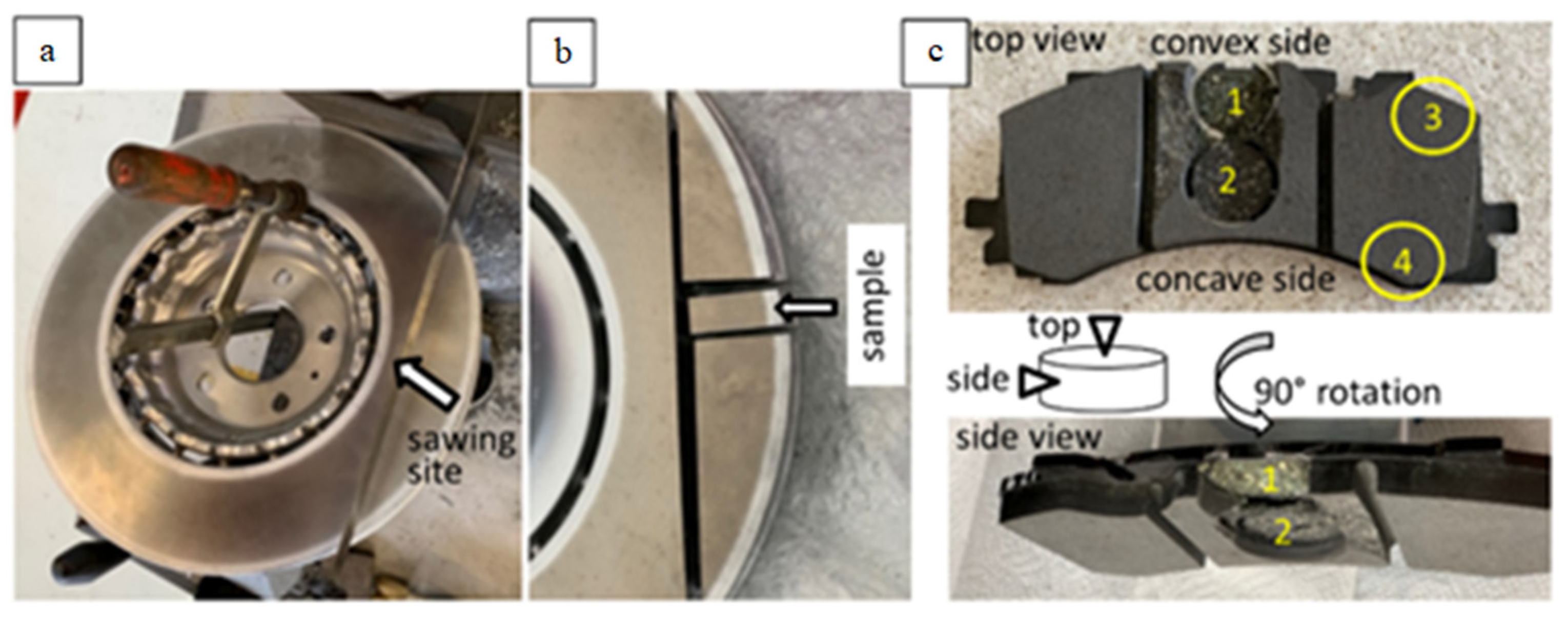
Brake disc: The new disc was sawn and a sample was taken for microscopic study (Figure 1a,b).
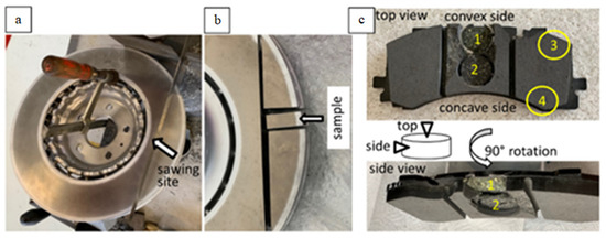
Figure 1.
Macro-photographs of the disc (a,b) and of the pads (c) showing the sampling sites on top view and side view, as well as a sketch of the examined samples marking top and side view (arrows).
Brake pads: Four samples from the new and four from the used pad (two from the center and two from the lateral part) were taken for study (Figure 1c). The samples were examined at their upper surface facing the disc (‘top view’, Figure 1c), as well as from the side (‘side view’, Figure 1c).
The brake pad samples were investigated: (i) as taken from the pad (untreated) and (ii) impregnated in epoxy and polished, in order to obtain a better imaging resolution and a better EDX signal.
The samples from both the disc and the pads were studied initially by light microscopy for general observations, and, the same samples, subsequently, by SEM for detailed characterization.
For the identification of the organic fibrous components of the pads in the pad interior toward the metal support, Fourier transform infrared spectroscopy (FTIR) was applied on selected samples.
2.3. SEM Analyses
SEM was applied to both for imaging, as well as for chemical analysis of the imaged particles by EDX. SEM images were mostly taken in Back Scattered Electron (BSE) mode, which depicts brightness intensity variations corresponding to the chemical variations, the degree of brightness correlating positively with the atomic number of the participating element, as well as with the particle’s thickness. Secondary Electron (SE) images, which emphasize the sample topography, were taken from the untreated samples. Element mapping was carried out on a number of sites. Element mapping illustrates the element distribution of the mapped particles and allows inferences on their chemical composition, based on the observed element combinations. The element mapping accuracy and quality diminish as the size of the mapped particles is reduced.
2.4. Image Processing
An in-house algorithm was applied for computing the absolute percentage of the carbonaceous particles. The algorithm was implemented in MATLAB. After applying a filter for noise reduction, the grey scale SEM image was binarized according to a threshold parameter defined after a doe investigation. Subsequently, a filter for morphological closing on the binary image was applied consisting of a reference circle geometry specified as input. This filter has been tested and the sensitivity on the final results has been analyzed. Finally, the algorithm computed the carbon percentage as the ratio of the number of black pixels with respect to the overall number of pixels of the image (no other black constituents participate in the pad composition). Thus, the computed results correspond to the black area fraction of the surface of the examined images. Six different SEM images were used for the carbonaceous particle percentage computations.
2.5. Particle Chracterization
Before proceeding to the results on the brake pads, some terminology clarifications, as well as characterization/classification criteria referring to the particles described below are given here briefly. In studies dealing with atmospheric pollutants, the general term ‘particulate matter’ (PM; a mixture of solid particles and liquid droplets suspended in the air) is used. PM may have a broad range of chemical composition and size. A widely accepted size subdivision for PM includes coarse (PM10: 2.5–10 µm), fine (PM2.5: 1–2.5 µm) and ultrafine (<0.1 µm) size scales. Particles that are 10 µm and smaller are mostly the ones causing health concerns, as they can become airborne for variable time periods and potentially be inhaled. Larger particles usually deposit on the ground or on other surfaces, from where they can be eventually partly re-suspended and/or further transported.
The constituents of the brake pads, as described below, cover a very wide size range extending far beyond the above described PM size scale. Size distribution data exist only for break wear (e.g., [5] and references therein). On the other hand, the brake pad constituents described here, are exclusively solid. The term ‘particle’ is applied in the present study, which includes single particles, as well as aggregates. Size-based subdivisions of particles >10 µm exist only for sedimentary rocks and cannot be applied here.
Conclusively, in the present paper, the following size subdivision is followed for the examined brake pad particles: ‘very large’ (on the order of a few hundreds of µm), ‘large’ (on the order of a few tens of µm), coarse (10–2.5 µm), fine (2.5–0.1 µm) and ultrafine (<0.1 µm).
3. Results
3.1. Brake Disc
The surface of the new disc, in light microscopy, shows a rough profile with regularly alternating grooves (Figure 2a). In SEM, small cavities and/or partial material detachment were observed (Figure 2b). Element mapping revealed the presence of mainly Fe, as well as C, S and some Al, the latter element identified only toward the disc rim. Its presence is probably related to Al-spraying of the disc surface at the periphery. Small amounts of Cr, Mn, Si and Ca, not depicted on the element mapping images (Figure 2c) of Figure 2b, were also detected. The material of the disc corresponds to cast iron. The disc is not coated.
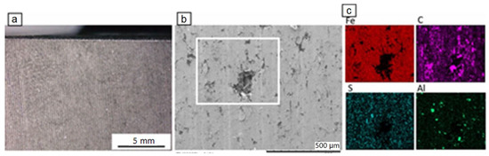
Figure 2.
Light microscopy image (a) and BSE-SEM image of the disc (b), together with element mapping (c) of the white square in (b).
3.2. Brake Pads
3.2.1. New Brake Pad
The new brake pad consists of a variety of components of different sizes, shapes and chemical composition. Parts of these components occur in the form of aggregates, while others are present as single particles. A general view of the pad observed from above and from the side reveals that it contains components of ‘very large’ and ‘large’ sizes randomly disseminated in a considerably finer matrix (Figure 3a–e). ‘Very large’ and ‘large’ particles include:
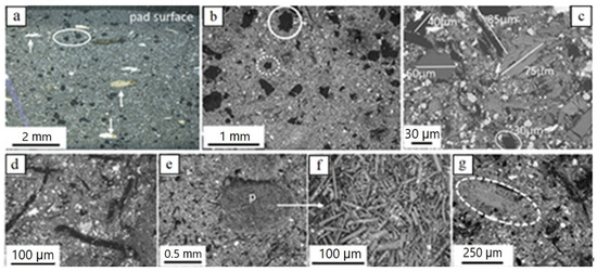
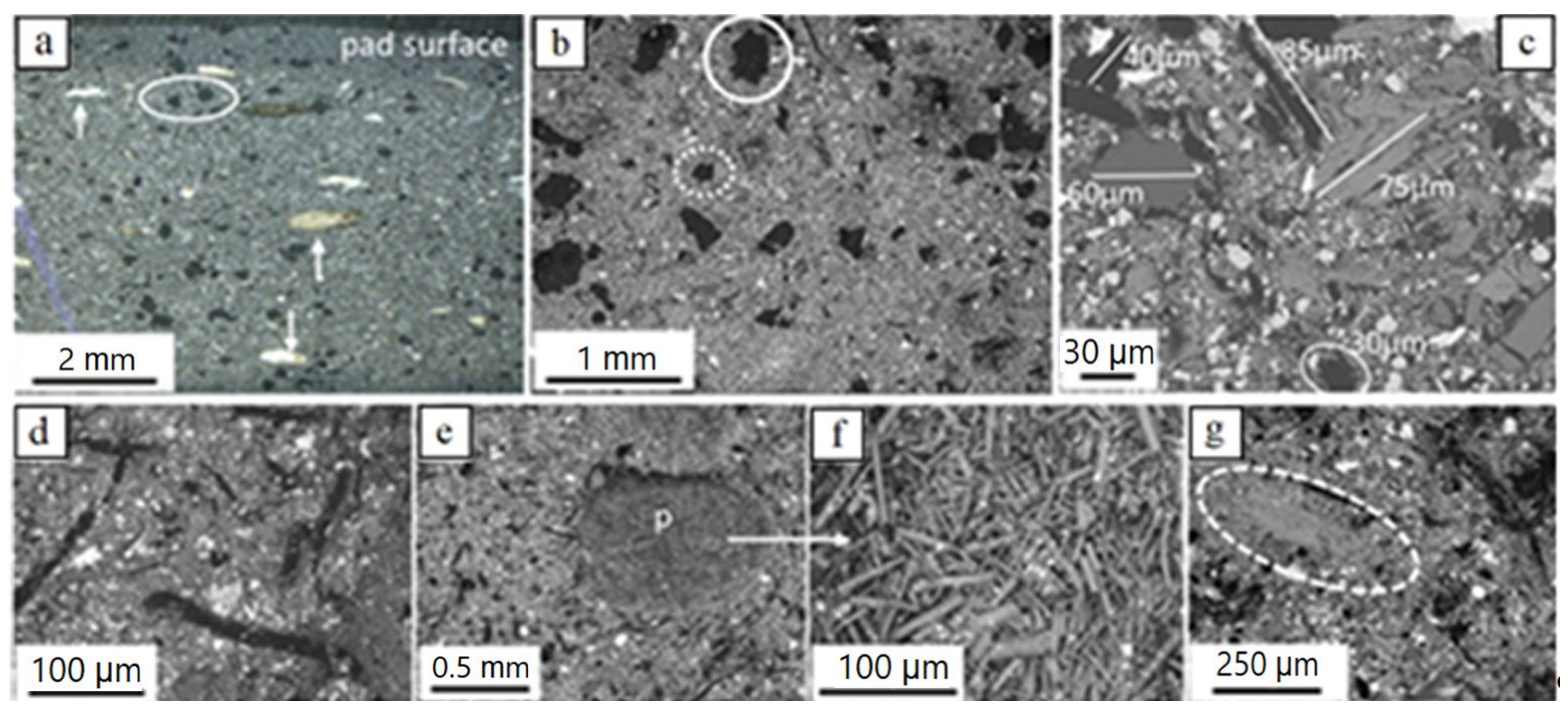
Figure 3.
Light microscopy (a) and BSE-SEM (b–g) images of the new brake pad; (a) irregularly shaped carbon particles (black, example encircled) and fiber-rich pockets (examples pointed by arrows); (b) ‘very large’ and ‘large’ irregular carbon particles (partly encircled with solid and dotted lines, respectively) in finer matrix; (c) various ‘large’ particles in finer matrix; (d) hair-like carbon particles (black) in finer matrix (e) fiber-rich pocket (p) and magnification in (f) with well visible fibers; (g) sheet-forming, elongate ‘large’ particle (grey encircled; K-titanate) in finer matrix. Brightness of images increases with element atomic number. Samples in (c) and (g) impregnated/polished, all others untreated; (a) side view (pad profile), all others top view (pad surface).
(i) Carbonaceous particles. Two types of carbonaceous particles occur: nearly equidimensional, as well as hair-like ones. The equidimensional particles are the largest one-phase particle constituents of the brake pads. They have a black color, irregular forms and theirs sizes reach a few hundred µm to roughly one mm (Figure 3a–c). The hair-like carbon particles are tens of µm wide and a hundred to a few hundreds of µm long (rarely several hundreds of µm) (Figure 3c,d).
(ii) Sheet-forming elongate particles, a few tens of µm in width and a few hundreds of µm long (Figure 3e,f). Based on EDX analyses, they usually consist of K and Ti (potassium titanate) and more rarely of Ca-Si-O.
Particles (aggregates) occurring only in ‘very large’ sizes include:
(iii) Fiber-rich pockets. They are white to yellowish under the light microscope, with round outlines, a mm to a few hundreds of µm large, and consist of fiber aggregates (Figure 3a,d,f). EDX analyses revealed that the fibers consist mainly of Mg, Al, Si, Ca and higher or lower amounts of Fe (Figure 3g), a composition indicative of the mineral vermiculite. In some samples, Na was also detected.
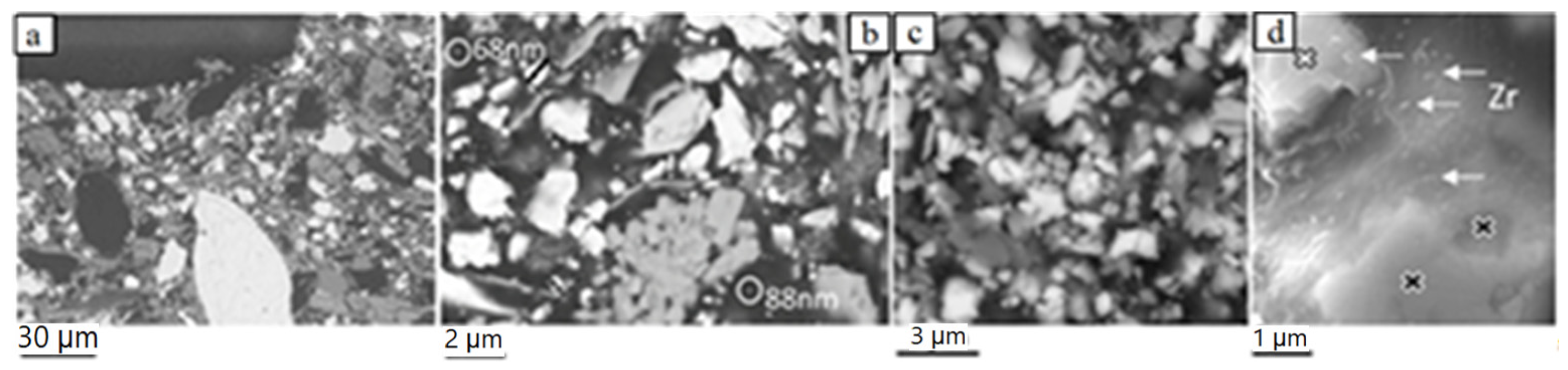
The brake pad matrix consists of particles with sizes predominantly in the fine- and the lower fraction of the coarse-scale (a few µm). These include hair-like carbon particles, individual fibers such as to those encountered in the fiber-rich pockets, as well as particles with irregular, sheet-forming (platy) and prismatic shapes (Figure 4a–c). Rarely, nearly spherical particles of fine- but also ultrafine-scales were recognized (Figure 4b,d). Ultrafine particle sizes were rarely detected either because the ultrafine material is highly compacted, thus hampering detection of single particles, or such sizes were not (or sparsely) included in pad construction.

Figure 4.
BSE-SEM images of the new brake pad surface showing the spectrum of particle shapes and sizes of the matrix. (a) coarse and fine matrix particles; a few ‘large’ particles are observed; (b,c) fine and less coarse matrix particles; two ultrafine particles are encircled in (b); (d) nearly spherical, ~100–150 nm to a few tens of nanometer-large Zr-bearing particles (analyzed particles indicated by arrows); black- and white-filled crosses mark analyzed sites of a Zr- and Ba-S-bearing phase, respectively. The samples are impregnated and polished. Image (a) is taken on side view (pad profile), all others on top view.
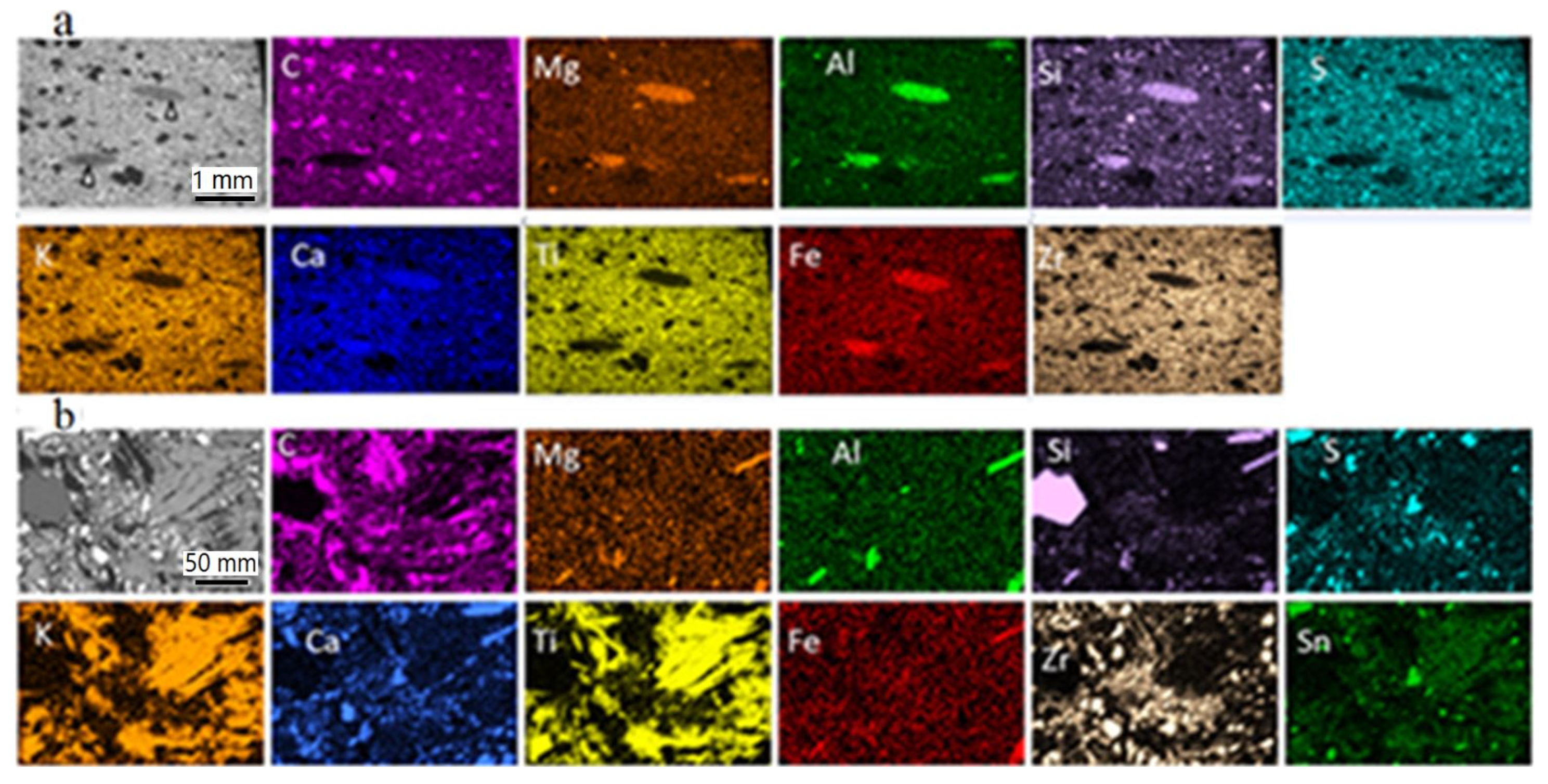
A large number of EDX analyses were carried out on numerous particle constituents of all sizes in the new pad. They showed the presence of the following elements: C, Al, Si, S, K, Ca, Ti, Fe, Zr, Sn, less Mg, Ba, Na and, rarely, Bi and Zn. Element mapping at different sites of the pad samples revealed that the particle constituents are composed of one or, mostly, several of the above elements in combination. Selected (representative) element mapping images are given in Figure 5.
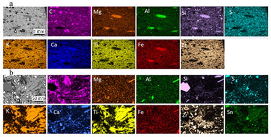
Figure 5.
BSE-SEM images (grey) and element mapping illustrating the element distribution in the new brake pad. (a) Overview of the uppermost ~3 mm of the pad profile (side view); grey lenticular parts (pointed by arrows) correspond to fiber-rich pockets; (b) detail of the pad surface (top view) showing ‘large’ and finer matrix constituents; in addition to the depicted elements, smaller amounts of Ba, Na, Sn (in a) and Bi (in b) were analyzed. The color intensity increases with the element concentration and thickness. Both samples were impregnated and polished.
The most commonly encountered particles of very large and large sizes were carbonaceous particles; the precise nature of the carbonaceous particles was not determined here. However, commonly used carbon-types are graphite and/or coke calcined petroleum coke. Sheet-forming very large and large particles are also common in the investigated pads and are usually made of K and Ti (potassium titanate). Individual fibers similar to those in the pockets dispersed in the pad consist mostly of Si, Al, Ca, Mg, Fe and some Na (vermiculite). The element combinations, together with the inferred chemical composition and presumed nature of very large, large and matrix (coarse, fine and ultrafine sizes) particles are numerous. They are listed in Table 1 and examples are illustrated in Figure 5 including an overview and larger scale mapping results. As well as the inferred (presumed) mineral phases listed in Table 1, the participation of additional mineral phases is also possible. It needs to be mentioned that the chemical composition and nature of mineral constituents, as listed in Table 1, is the same in both the new and the used brake pad.

Table 1.
Particle types in the new brake pad: morphology, qualitative chemical composition and corresponding (presumed) mineral phases.
3.2.2. Used Brake Pad
The used brake pad is asymmetrically worn out, more at the convex side than at the concave side and slightly more at the central part than at the sides. The same particle- and particle aggregate-types with the same morphological characteristics, as in the new pad, can be identified (Figure 6a,b). Numerous EDX analyses revealed the presence of the same elements, as those found in the new pad: C, Al, Si, S, K, Ca, Ti, Fe, Zr, Sn, less Mg, Ba and Na, as well as small amounts of Bi. A series of element mapping analyses points to the presence of pad constituents chemically identical to those of the new pad (Figure 6a).

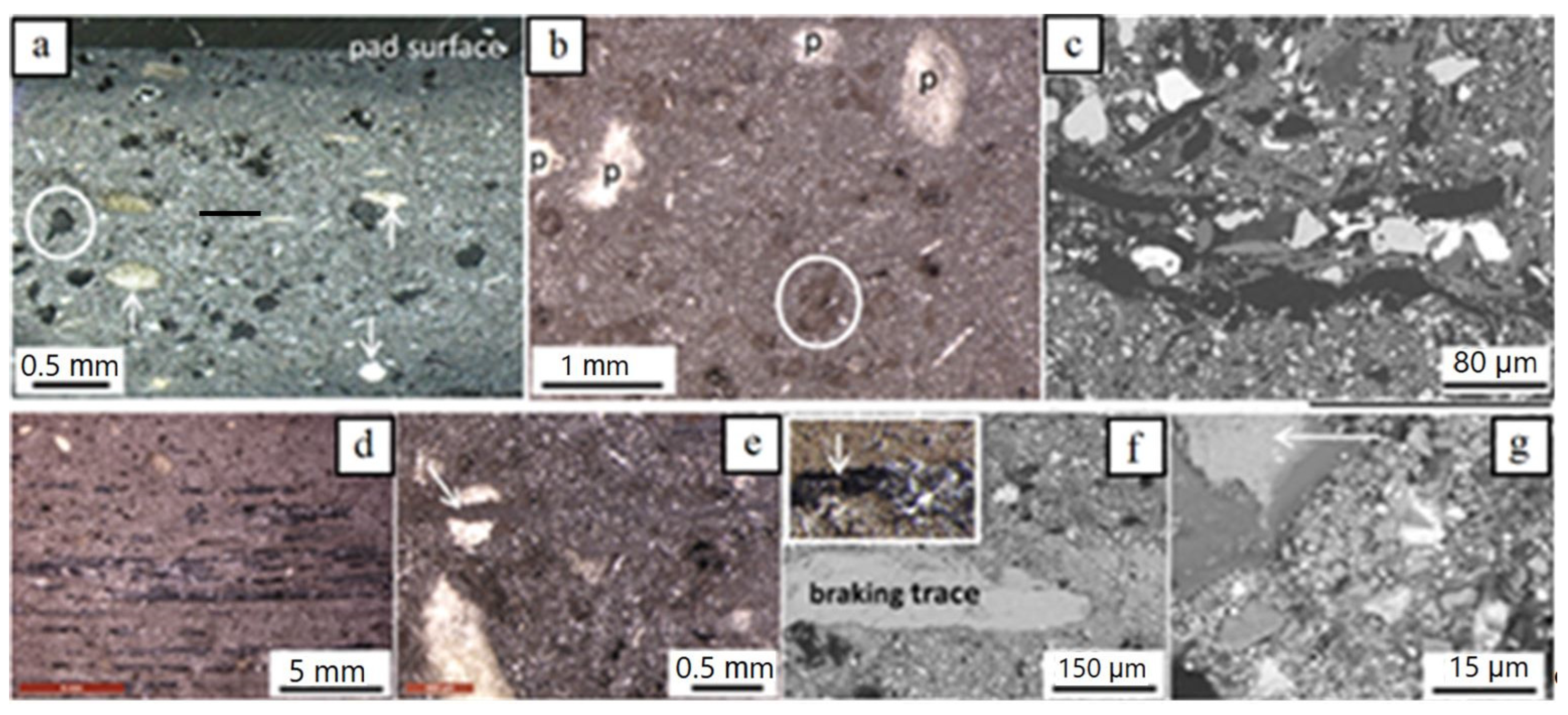
Figure 6.
Light microscopy (a,b,d,e and inset in f) and BSE-SEM images (c,f,g) of the used brake pad. (a) Side view (profile) of the uppermost ~3 mm showing mainly the ‘very large’ constituents (carbon, partly encircled) and fiber-rich pockets, arrows; (b) pad surface with fiber-rich pockets (p), carbon (partly encircled and sheet-forming particles (thin white), as well as abundant brownish material partly altering the black color of carbon particles and pockets; (c) pad surface illustrating details of ‘large’ particles and matrix constituents; (d) pad surface with brownish material and braking traces (parallel black stripes); (e) pad surface with dispersed brownish material and a layer of it crosscutting a fiber-rich pocket (arrow); (f) detail of a braking line in SEM; inset shows the braking line in light microscopy); (g) detail of a braking line (arrow) and of brownish material in SEM (abundant fine grains in the largest part of the image). Images (a,c,f,g) are impregnated samples, all others untreated.
As well as the above mentioned similarities, some striking features that differentiate the used from the new pad could be distinguished, summarized as follows:
(i) Opposite to the new brake pad, which has a rough surface, the used pad surface is smoother and flatter. As a result of this flattening, some constituents partly sticking out of the surface in the new pad (e.g., matrix fibers) or lying at a slightly lower level have been entirely incorporated inside the main body of the used pad.
(ii) The brake pad surface bears numerous braking trace lines; they are black, mm to tens of µm long (Figure 6d,f) and more pronounced at the front part of the pad than at the rear. Sometimes, the trace lines are surrounded by another phase (darker in Figure 6g) pre-existing in the pads (see below).
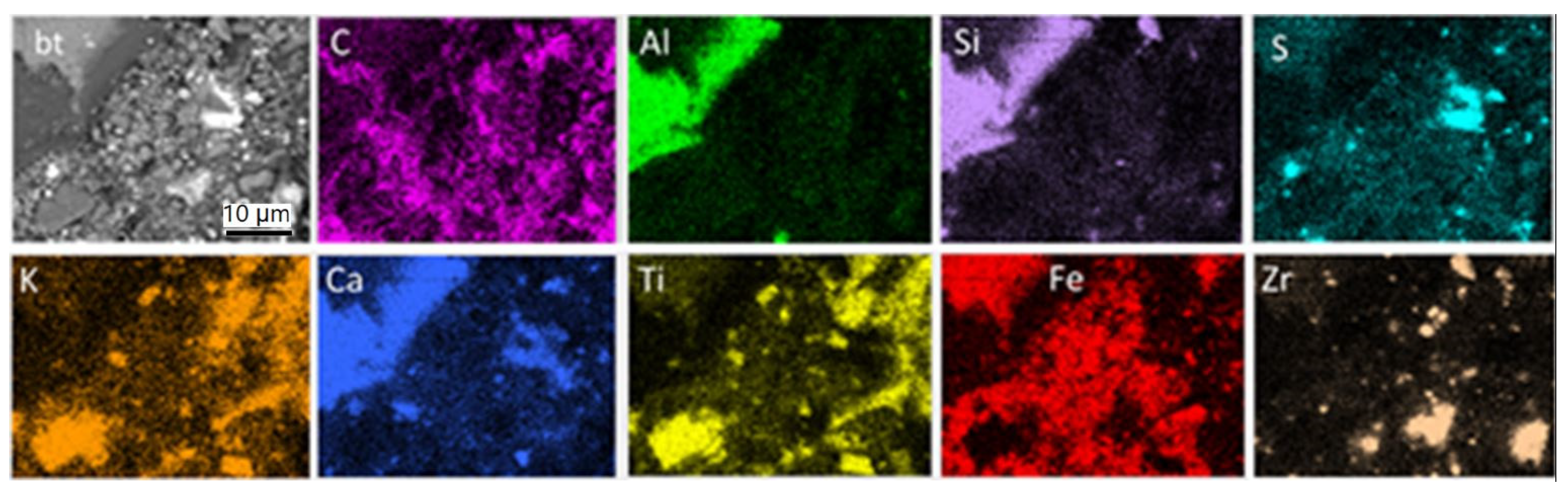
(iii) Brown-colored fine-grained material is disseminated all over the used pad surface and enriched close to braking traces (Figure 6f). Moreover, thin parallel layers enriched in fine-grained brownish material and following the direction of the braking traces are present in some cases. Some of these layers crosscut fiber-rich pockets (Figure 6e, arrow), clearly showing that the layers are a late feature resulting during pad use. The same inference can be drawn by the partial alteration of the black color of the carbon constituents and of the white color of the pockets (Figure 6b). Based on EDX analyses and element mapping, both the braking traces and the fine brownish material on the used pad surface consist of Fe (Figure 7), which argues that they derive, to a large extent, from the disc. EDX mapping indicates, in addition, carbon particles’ enrichment of the pad surface, as well as pre-existing elements and components, as in the new pads (Figure 7). The dark phase surrounding the brake trace in Figure 6 is a Ca-Al-silicate, already identified in both the new and used pad composition.
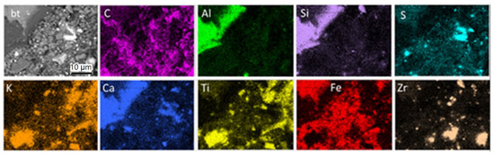
Figure 7.
SEM-BSE image (grey) and element mapping illustrating the element distribution on the used brake pad surface. (bt): braking trace. Untreated sample, top view.
3.2.3. Brake Pad Interior—Side Close to Metal Support
The part of the brake pad interior close to the metal support is rich in organic material. Yellow-greenish colored fiber aggregates occur in a black-grey matrix (Figure 8a). Fourier transform infrared spectroscopy (FTIR, Figure 8b,c), an analytical technique based on infrared spectra absorbed by the analyzed substance, was applied to determine the nature of the above organic material. The results showed that the yellow-greenish aggregates consist of aramid (kevlar), a heat resistant, strong synthetic fiber-type and the matrix of phenolic resin, a material commonly used as a binder in brake pads because of its thermal resistant properties.
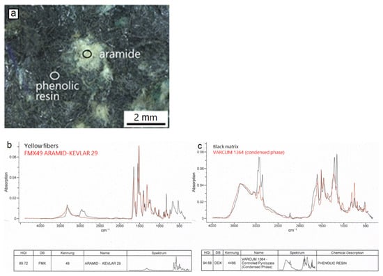
Figure 8.
Light microscopic image (a) illustrating representative examples of aramid aggregates and phenolic resin matrix (circles) at the pad interior, close to the metal support. FTIR Spectra (b,c) of the pad parts (black lines) as well as of the corresponding reference materials (red lines).
3.2.4. Carbonaceous Material—Image Processing
Carbonaceous particles are prominent ingredients in the examined pads. They occur in different sizes covering the entire spectrum from ‘very large’ to fine scales. Selection of this particle type was based on the fact that carbon is an important ingredient combining central parameters required in brake pad performance (lubrication, friction coefficient stabilization, heat dissipation, noise reduction), as well as satisfactory wear rate levels (e.g., [31,32]). Moreover, their black color makes them promising for providing reliable image processing results. The image processing methodology used here is described in the experimental Section 2.4.
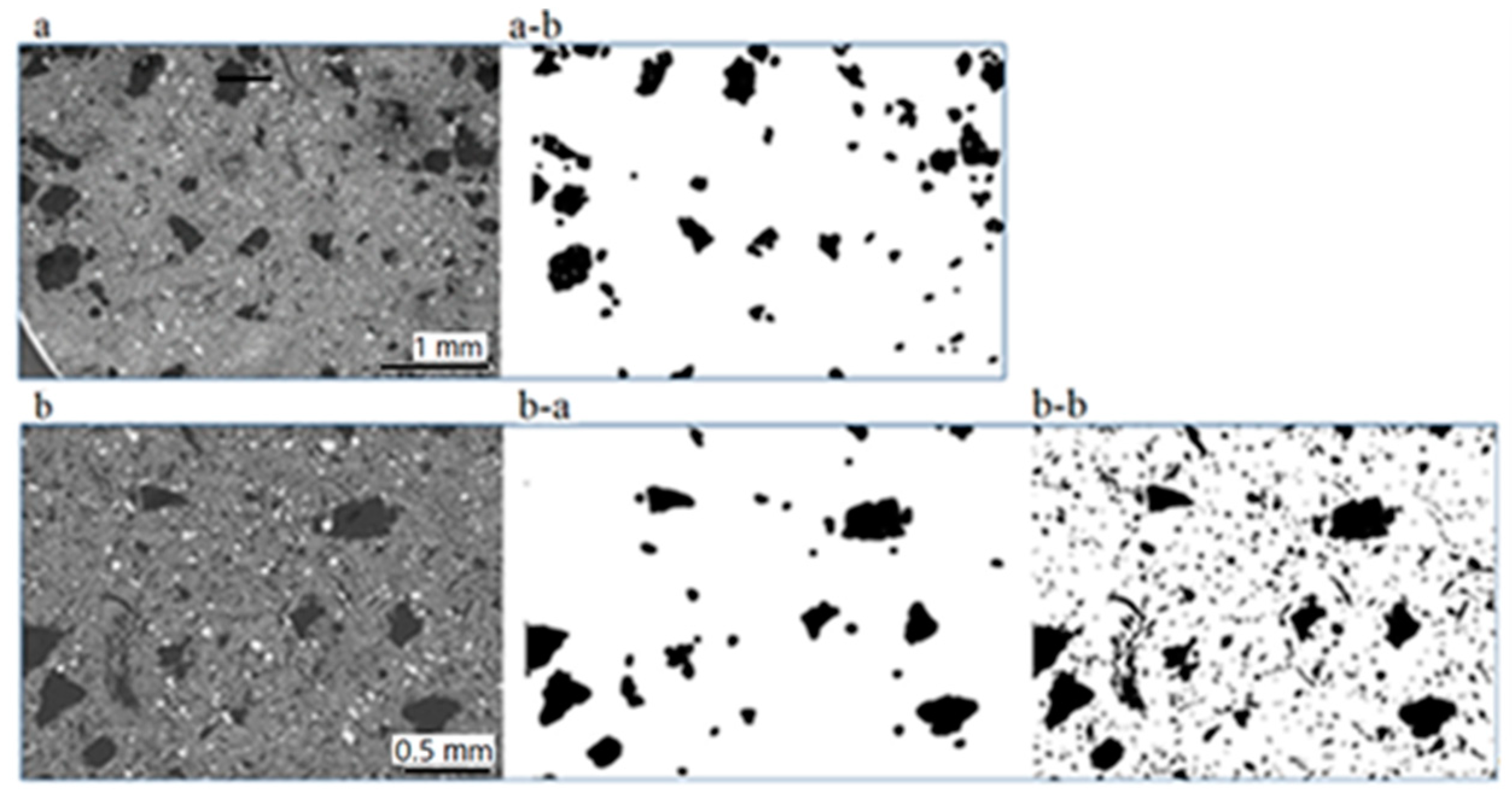
Image processing, as shown in Figure 9 resulted in a percentage of ~8% when considering the larger carbonaceous particles (~500–100 µm), Figure 9a-b,b-a. When sizes down to a few tens of µm are considered in addition, the above percentage is nearly doubled (~16%), Figure 9b-b. Implications of these results are discussed further below in Section 4 (Discussion). The algorithm computed the carbon percentage as the ratio of the number of black pixels with respect to the overall number of pixels of the image.
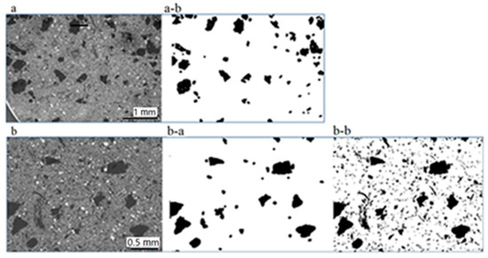
Figure 9.
SEM (a,b) and binarized images (a-b,b-a,b-b) used for the calculation of the carbonaceous particle percentages: Considering particles 0.5–0.1 mm (a-b), (b-a), resulting percentage is 8%; including sizes down to ca. 20 µm (b-b), resulting percentage is 15.5%.
4. Discussion
SEM/EDX analyses of the brake assembly studied here provided data on the composition of the disc and of the brake pads, including chemistry, sizes, forms, way of distribution and, partly, proportions of the individual pad constituents. These properties principally control the performance of the brake system, as well as the emitted wear.
At least 21 different substances were identified in the investigated brake pads. With the exception of carbonaceous particles, which consist of mainly carbon, the other constituents are composed of different combinations of the following elements: C, Al, Si, S, K, Ca, Ti, Fe, Zr, Sn, less Mg, Ba, Na and rarely Bi and Zn, in the form of oxides, sulfides, sulfates, silicates and K-titanate. In addition, organic substances, namely aramid and phenolic resin have been identified. They are enriched in the pad interior, mostly close to the metal interface.
The size spectrum of the pad constituents is very wide extending from hundreds of micrometers to a few micrometers and, more rarely, down to a few hundreds to tens of nanometers. The largest among them are those mostly delineating the thermal and mechanical properties of the pad. In the investigated pads, the largest particles (a few hundreds of micrometers) are irregularly shaped, nearly equidimensional and carbonaceous followed by sheet-forming K-titanate. Based on image processing data, the proportion of larger carbonaceous particles (~0.5–0.1 mm) on the pad surface is ~8%. As C-particles occur in a much wider size range, down to a few micrometers, the proportion of carbonaceous material goes up to ~16%.
There is a characteristic texture of the brake pads, as far as the arrangement of the differently large particles are concerned: the larger particles are set in a considerably finer-grained groundmass constituting the matrix. This pattern creates more voids between larger and smaller particles, thus affecting the porosity, which is related to noise effects and thermal conductivity. Moreover, the platy morphology of the above mentioned large sized ingredients (graphite, sheet-forming K-titanate) does not favor porosity reduction during sliding in brake operation, as this would have happened with fibrous components intruding potentially into existing voids. Although primarily related to the properties of the pad, the above arrangement of the pad constituents may also have an influence on the wearing mechanism and possibly also on the sizes of the emitted wear (see further below).
The matrix constituents of the pad, which range in size mostly between coarse and fine scales (a few micrometers) are dominated by Zr-bearing material (Zr-oxide and Zr-silicate), which is the hardest pad constituent. Other matrix particles consist mainly of different combinations of Sn, S, Ca, Mg, Si and, to a lesser extent, Fe.
All of the above described characteristics are common for both the new and used brake pads. The used brake pad shows, however, a striking difference compared to the new one in that abundant coarse and fine Fe particles occur on its surface, probably originating from the brake disc. Fe-bearing stripes corresponding to braking traces are also observed on the surface of the used pad. The coarse and fine Fe particles reach the surface of the brake pad by a mechanism probably involving the action of the hard, Zr-bearing pad constituents. During braking, a mixture of materials are worn out from the pad and disc to produce a mixture of debris. Part of this debris becomes airborne and part of it deposits either on the ground or on the brake assembly partners. The highly heterogeneous composition of the pad, which consists of harder and softer materials, results in an uneven alteration of the participating components. The components worn out more easily are the softer ones. The harder material, represented here by Zr-bearing minerals, is resistant to friction and after initial consumption of the softer ingredients it is expected to stick out of the pad surface. In that way, due to their hardness, Zr-particles may scratch-off iron fragments from the disk surface. These can be either immediately emitted in ambient air or deposited on the disc/pad surfaces. Previous studies (e.g., [33] and references therein) reported similar observations, where the surface of the used brake pad is clearly enriched in Fe-oxide and mixed with other pad components giving rise to an Fe-rich layer. Moreover, in an earlier experimental work with the same pad and disc types as those studied here, brake wear was collected and studied in detail by SEM and TEM [34]. The results of the above investigation showed that Fe was the most frequent element in airborne particles of all sizes (ultrafine to coarse). This is in line with the abundance of Fe-bearing particles on the surface of the used brake pad observed here. The second most frequent element, Ca, was reported by [34] among airborne particle wear, especially in ultrafine and fine size ranges, sometimes in combination with S. Based on the results of the present paper, Ca+/-S-phases of the pad include CaO and CaSO4. They often occur in the matrix, both in coarse and fine sizes but have been found also in larger sizes (tens of micrometers large). It seems that CaO and CaSO4 are prone to wear production in the concrete pad formulation. In contrast, airborne particles with the composition of the largest constituents of the pads (carbonaceous, K-titanate) are rarely mentioned in the above study. It is noted that the percentage of carbon particles in the investigated pads was found to reach ca. 16%. With such a participation percentage, it would be expected that carbonaceous particles would have been more frequent among the airborne wear particles, but this is not the case. Thus, as well as the degree of hardness of the pad constituents, their shape, size and distribution pattern over the pad surface are also parameters that probably play a role in the type, size and abundance of the produced wear.
Another noticeable characteristic of airborne particles mentioned by [34] is their prevailing rounded outlines. This implies that the particles have been possibly milled between the friction partners before emission. Sharp-edged particles are reported rarely and are of larger sizes (>~350 nm); they likely escaped from the braking system unprocessed (not involved in milling). The rarity of angular wear particles implies that particle milling prior to emission is a predominant mechanism.
The results of the present study stress the importance of electron microscopy for understanding the role of the morphology, chemistry and arrangement of the brake assembly components, thus providing additional data to the scientific community and industry to optimize the pad components for more efficient operation while simultaneously minimizing the emitted wear and enhancing the brake assembly performance. The results may also help comprehend the mechanism involved in the production of wear emissions, which seems to be related to the relative abundance, morphology, chemical composition and properties of the participating constituents. The important properties of the pad constituents are stability, friction coefficient and wear rate.
5. Conclusions
The present work aimed at elucidating the morphology, chemical composition, diversity, distribution and alteration of the brake assembly components, providing an analysis of the origins of brake particles. Therefore, a set of new and used brake discs and pads have been used and examined by SEM/EDX with image processing and partly FTIR analysis. Based on SEM imaging and EDX analyses, at least 21 different substances are included in the brake pads. They consist of the following elements:
- C, Al, Si, S, K, Ca, Ti, Fe, Zr, Sn, less Mg, Ba, Na and, rarely, Bi and Zn, combined in the form of oxides, sulfides, sulfates, silicates and K-titanate,
- carbonaceous particles, consisting mainly of C, and
- organic substances (aramid and phenolic resin).
The pad constituents encompass a very wide size spectrum extending from hundreds of micrometers to hundreds of nanometers, rarely down to tens of nanometers. The largest constituents are carbonaceous particles, K-titanate and pocket-forming Mg, Al, Si, Ca and Fe fiber aggregates.
The pads are characterized by a distinctive texture, whereby the larger constituents are set in a considerably finer-grained matrix. This arrangement pattern may be related to the wear mechanism and the resulting wear emissions. The matrix material of the pad is dominated by:
- Zr-particles,
- particles consisting of S, Ca, Mg, Si, Ti and, to a lower extent, Ba and Fe in different combinations.
Prevailing sizes in the matrix are mainly of coarse and fine scales.
Abundant Fe particles, a few micrometers large, occur on the surface of the used pad making up an Fe-rich layer. They originate from the disc and reach the surface of the brake pad possibly by a mechanism of differential consumption of brake pad constituents, based mainly on their hardness. The hard Zr particles may be responsible for the extraction of Fe particles from the disc during abrasion.
The wear mechanism, as well as the types and sizes of the produced wear, are functions not only of the mechanical properties of the pad constituents but relate also to their shape, size and arrangement over the pad surface. The mapping illustrates the element distribution in the new and the used brake pad.
Author Contributions
Conceptualization, P.D.E., S.G.; methodology, P.D.E., S.G.; software, V.P.; validation, V.P., P.D.E. and D.L.; formal analysis, P.D.E. and D.S.; investigation, D.S. and P.D.E.; resources, D.S.; data curation, D.S. and V.P.; writing—original draft preparation, P.D.E.; writing—review and editing, S.G. and D.S.; visualization, V.P.; supervision, D.L.; project administration, P.D.E.; funding acquisition, P.D.E. All authors have read and agreed to the published version of the manuscript.
Funding
The present work was carried out within the framework of a project funded by the Swiss Federal Office for the Environment (BAFU) (Nr. Q473-1471).
Data Availability Statement
All data presented in this study are available on request from the corresponding author. The data are not publicly available due to a confidentiality agreement with the part providers.
Acknowledgments
The authors gratefully acknowledge the contribution of the late A Liati in this work. We dedicate this work to her memory. Ch. Walder, Department of Functional Polymers, Empa, is acknowledged for his help with the FTIR analyses.
Conflicts of Interest
The authors declare no conflict of interest. The funders had no role in the design of the study; in the collection, analyses, or interpretation of data; in the writing of the manuscript, or in the decision to publish the results.
References
- Harrison, R.M.; Jones, A.M.; Gietl, J.; Yin, J.; Green, D.C. Estimation of the Contributions of Brake Dust, Tire Wear, and Resuspension to Nonexhaust Traffic Particles Derived from Atmospheric Measurements. Environ. Sci. Technol. 2012, 46, 6523–6529. [Google Scholar] [CrossRef] [PubMed]
- Lawrence, S.; Sokhi, R.; Ravindra, K.; Mao, H.; Prain, H.D.; Bull, I. Source apportionment of traffic emissions of particulate matter using tunnel measurements. Atmos. Environ. 2013, 77, 548–557. [Google Scholar] [CrossRef]
- Padoan, E.; Amato, F. Chapter 2—Vehicle non-exhaust emissions: Impact on air quality. In Non-Exhaust Emissions; Amato, F., Ed.; Academic Press: Cambridge, MA, USA, 2018; pp. 21–65. [Google Scholar]
- Kumar, P.; Pirjola, L.; Ketzel, M.; Harrison, R.M. Nanoparticle emissions from 11 non-vehicle exhaust sources—A review. Atmos. Environ. 2013, 67, 252–277. [Google Scholar] [CrossRef] [Green Version]
- Grigoratos, T.; Martini, G. Brake wear particle emissions: A review. Environ. Sci. Pollut. Res. 2015, 22, 2491–2504. [Google Scholar] [CrossRef] [Green Version]
- Hagino, H.; Oyama, M.; Sasaki, S. Airborne brake wear particle emission due to braking and accelerating. Wear 2015, 334–335, 44–48. [Google Scholar] [CrossRef]
- van der Gon, H.D.; Hulskotte, J.; Jozwicka, M.; Kranenburg, R.; Kuenen, J.; Visschedijk, A. Chapter 5—European emission inventories and projections for road transport non-exhaust emissions: Analysis of consistency and gaps in emission inventories from EU member states. In Non-Exhaust Emissions; Amato, F., Ed.; Academic Press: Cambridge, MA, USA, 2018; pp. 101–121. [Google Scholar]
- Lyu, Y.; Leonardi, M.; Wahlström, J.; Gialanella, S.; Olofsson, U. Friction, wear and airborne particle emission from Cu-free brake materials. Tribol. Int. 2020, 141, 105959. [Google Scholar] [CrossRef]
- Dhir, B.; Sharmila, P.; Saradhi, P.P.; Sharma, S.; Kumar, R.; Mehta, D. Heavy metal induced physiological alterations in Salvinia natans. Ecotoxicol. Environ. Saf. 2011, 74, 1678–1684. [Google Scholar] [CrossRef]
- Shupert, L.A.; Ebbs, S.D.; Lawrence, J.; Gibson, D.J.; Filip, P. Dissolution of copper and iron from automotive brake pad wear debris enhances growth and accumulation by the invasive macrophyte Salvinia molesta Mitchell. Chemosphere 2013, 92, 45–51. [Google Scholar] [CrossRef]
- Österle, W.; Kloß, H.; Urban, I.; Dmitriev, A.I. Towards a better understanding of brake friction materials. Wear 2007, 263, 1189–1201. [Google Scholar] [CrossRef]
- Ostermeyer, G.P.; Müller, M. New insights into the tribology of brake systems. Proc. Inst. Mech. Eng. Part D J. Automob. Eng. 2008, 222, 1167–1200. [Google Scholar] [CrossRef]
- Söderberg, A.; Andersson, S. Simulation of wear and contact pressure distribution at the pad-to-rotor interface in a disc brake using general purpose finite element analysis software. Wear 2009, 267, 2243–2251. [Google Scholar] [CrossRef]
- Nishiwaki, M.; Abe, K.; Yanagihara, H.; Stankovic, I.; Nagasawa, Y.; Wakamatsu, S. A Study on Friction Materials for Brake Squeal Reduction by Nanotechnology; SAE International: Warrendale, PA, USA, 2008. [Google Scholar]
- Dmitriev, A.I.; Österle, W. Modelling the Sliding Behaviour of Tribofilms Forming During Automotive Braking: Impact of Loading Parameters and Property Range of Constituents. Tribol. Lett. 2014, 53, 337–351. [Google Scholar] [CrossRef]
- Faga, M.G.; Casamassa, E.; Iodice, V.; Sin, A.; Gautier, G. Morphological and structural features affecting the friction properties of carbon materials for brake pads. Tribol. Int. 2019, 140, 105889. [Google Scholar] [CrossRef]
- Dienwiebel, M.; Pradeep, N.; Verhoeven, G.S.; Zandbergen, H.W.; Frenken, J.W.M. Model experiments of superlubricity of graphite. Surf. Sci. 2005, 576, 197–211. [Google Scholar] [CrossRef]
- Xiao, L.; Chung, D.D.L. Mechanical energy dissipation modeling of exfoliated graphite based on interfacial friction theory. Carbon 2016, 108, 291–302. [Google Scholar] [CrossRef]
- Nian, J.; Si, Y.; Guo, Z. Advances in atomic-scale tribological mechanisms of solid interfaces. Tribol. Int. 2016, 94, 1–13. [Google Scholar] [CrossRef]
- Eriksson, M.; Jacobson, S. Tribological surfaces of organic brake pads. Tribol. Int. 2000, 33, 817–827. [Google Scholar] [CrossRef]
- Österle, W.; Dmitriev, A.I. Functionality of conventional brake friction materials—Perceptions from findings observed at different length scales. Wear 2011, 271, 2198–2207. [Google Scholar] [CrossRef]
- Kwak, J.-H.; Kim, H.; Lee, J.; Lee, S. Characterization of non-exhaust coarse and fine particles from on-road driving and laboratory measurements. Sci. Total Environ. 2013, 458–460, 273–282. [Google Scholar] [CrossRef]
- Wahlström, J.; Olofsson, U. A field study of airborne particle emissions from automotive disc brakes. Proc. Inst. Mech. Eng. Part D J. Automob. Eng. 2015, 229, 747–757. [Google Scholar] [CrossRef]
- Chasapidis, L.; Grigoratos, T.; Zygogianni, A.; Tsakis, A.; Konstandopoulos, A.G. Study of Brake Wear Particle Emissions of a Minivan on a Chassis Dynamometer. Emiss. Control. Sci. Technol. 2018, 4, 271–278. [Google Scholar] [CrossRef] [Green Version]
- Iijima, A.; Sato, K.; Yano, K.; Kato, M.; Kozawa, K.; Furuta, N. Emission Factor for Antimony in Brake Abrasion Dusts as One of the Major Atmospheric Antimony Sources. Environ. Sci. Technol. 2008, 42, 2937–2942. [Google Scholar] [CrossRef]
- Mathissen, M.; Grochowicz, J.; Schmidt, C.; Vogt, R.; zum Hagen, F.H.; Grabiec, T.; Steven, H.; Grigoratos, T. A novel real-world braking cycle for studying brake wear particle emissions. Wear 2018, 414–415, 219–226. [Google Scholar] [CrossRef]
- Hulskotte, J.H.J.; Roskam, G.D.; van der Gon, H.A.C.D. Elemental composition of current automotive braking materials and derived air emission factors. Atmos. Environ. 2014, 99, 436–445. [Google Scholar] [CrossRef]
- Day, A. Braking of Road Vehicles; Elsevier: Amsterdam, The Netherlands, 2014; p. 488. [Google Scholar]
- Österle, W.; Griepentrog, M.; Gross, T.; Urban, I. Chemical and microstructural changes induced by friction and wear of brakes. Wear 2001, 251, 1469–1476. [Google Scholar] [CrossRef]
- Ostermeyer, G.P.; Dilnot, A.; Lange, J. Analysis of Friction in Brakes on a Virtual AK-Master Test Rig; Fortschritt-Berichte VDI Reihe 12—Verkehrstechnik, Fahrzeugtechnik; VDI: Duüsseldorf, Germany, 2012; Volume 759, pp. 168–182. [Google Scholar]
- Cho, M.H.; Ju, J.; Kim, S.J.; Jang, H. Tribological properties of solid lubricants (graphite, Sb2S3, MoS2) for automotive brake friction materials. Wear 2006, 260, 855–860. [Google Scholar] [CrossRef]
- Gilardi, R.; Alzati, L.; Thiam, M.; Brunel, J.-F.; Desplanques, Y.; Dufrénoy, P.; Sharma, S.; Bijwe, J. Copper Substitution and Noise Reduction in Brake Pads: Graphite Type Selection. Materials 2012, 5, 2258–2269. [Google Scholar] [CrossRef] [Green Version]
- Österle, W.; Deutsch, C.; Gradt, T.; Orts-Gil, G.; Schneider, T.; Dmitriev, A.I. Tribological screening tests for the selection of raw materials for automotive brake pad formulations. Tribol. Int. 2014, 73, 148–155. [Google Scholar] [CrossRef]
- Liati, A.; Schreiber, D.; Lugovyy, D.; Gramstat, S.; Eggenschwiler, P.D. Airborne particulate matter emissions from vehicle brakes in micro- and nano-scales: Morphology and chemistry by electron microscopy. Atmos. Environ. 2019, 212, 281–289. [Google Scholar] [CrossRef]


Publisher’s Note: MDPI stays neutral with regard to jurisdictional claims in published maps and institutional affiliations. |
© 2022 by the authors. Licensee MDPI, Basel, Switzerland. This article is an open access article distributed under the terms and conditions of the Creative Commons Attribution (CC BY) license (https://creativecommons.org/licenses/by/4.0/).