Article

Potential Uncertainties in the Analysis of Low-Wavenumber Asymmetries Caused by Aliasing Center in Tropical Cyclones

College of Meteorology and Oceanography, National University of Defense Technology, Changsha 410073, China
*
Author to whom correspondence should be addressed.
Atmosphere 2019, 10(6), 300; https://doi.org/10.3390/atmos10060300
Submission received: 10 March 2019 / Revised: 17 May 2019 / Accepted: 21 May 2019 / Published: 1 June 2019
(This article belongs to the Special Issue Advancements in Mesoscale Weather Analysis and Prediction)

Abstract

:
Variations in both symmetric wind components and asymmetric wave amplitudes of a tropical cyclone depend on the location of its center. Because the radial structure of asymmetries is critical to the wave–mean interaction, this study, under idealized conditions, examines the influences of a center location on the radial structure of the diagnosed asymmetries. It has been found that the amplitudes of aliasing asymmetries are mainly affected by the initial symmetric fields. Meanwhile, the radial structure of asymmetry is controlled by the aliasing direction. Sensitivity tests on the location of the center were employed to emphasize the importance of the aliasing direction using angular momentum equations. With a small displacement, the tendencies of azimuthal tangential wind are found to reverse completely when the center shifts to a different direction. This work concludes that the diagnostic results related to asymmetric decomposition should be treated rigorously, as they are prone to inaccuracies, which in turn affect cyclone prediction.

1. Introduction

The development of observational techniques and the enhancement of numerical simulations not only improve the precision of tropical cyclone (TC) prediction but also enrich the understanding of the finer structures of TCs. The 48-h track prediction skill has increased by 45% in the last 15 years, while the prediction of TC intensity and structure is still progressing at a sluggish pace [1,2]. The shortcomings in understanding the cyclone intensification mechanism are thought to be the limitations of the intensity prediction skill. Intensification mechanisms such as a conditional instability of the second kind (CISK) [3], cooperative intensification [4], wind-induced air–sea exchange (WISHE) [5,6], and the rotating convective updraft (RCU) theory [7,8] are widely known. Most of the theories based on axisymmetric considerations could be labeled as symmetric intensification mechanisms [8]. The intensification of a cyclone is known to result from symmetric processes such as symmetric convective heating and the inward transportation of an absolute angular momentum. Meanwhile, according to recent researches, more attention must be paid to the asymmetries as they may help explain temporary intensity variations [8,9,10]. Theories that emphasize the role of asymmetries could be labeled as asymmetric intensification mechanisms. Regardless of the perspective, both the mechanisms are based on a cylindrical coordinate system. The ordinate origin as the location of a TC’s center is a simplistic and straightforward description of TCs. The asymmetric structures defined as perturbations from the azimuthal mean may also be consistent with realistic features such as the spiral rain band [11]. Moreover, a few widely used metrics, including the radius of maximum wind (RMW), the radius of maximum radial wind (RMRW), the accumulated cyclone energy, the integrated kinetic energy, and the TC phase, were also calculated according to the knowledge of the TC center [12,13]. Therefore, finding an accurate location as the ordinate origin is of great consequence to describing the TC system.
Asymmetric intensification theories confirm that the symmetric TC circulation can be intensified by diabatic heat released by asymmetric convective systems [14,15,16,17,18]. However, there is no consensus over the role of the wave–mean flow interaction. For example, Persing et al. [19] showed that generally asymmetric eddy processes spin down the mean vortex through down-gradient effects, which was confirmed Yang et al. [20]. However, during periods of rapid intensification at the eyewall near the top of the boundary layer, eddy processes mix up gradients and lead to a spin-up effect of the mean vortex. The contradicting conclusions on the roles of asymmetry might be explained by the different numerical treatments of small-scale processes [21]. According to Gao et al., an anti-clockwise tailing structure increases the mean tangential wind, while a clockwise tailing structure decreases the same [22]. Therefore, the accuracy of radial tilting of asymmetries play an important role in diagnosing the contribution of the wave–mean interaction. This leads to a couple of speculations—are the radial structures of asymmetries sensitive to the center location? To what extent could the location of the center affect the diagnostic analysis?
There is no standard definition of a TC’s center. The centers are computed with a variety of center-finding algorithms, along with observations and modeling data. Studies using radar data define the center as the point that maximizes the mean tangential wind (MMTW) [23,24]. Some studies aimed at analyzing modeling data have used centroid algorithms, while choosing the size of the calculated domain through artificial means [25,26]. To simplify the definition, previous research defined the center by using domain extremes directly, such as a pressure minima [27]. Recently, Hou proposed a flow pattern-based algorithm in a numerical study [28]. In spite of the differences in restriction conditions of center-finding algorithms, most of the existing algorithms are classified into three distinct groups: local extreme, weighted grid point, and minimization of azimuthal variance (MAV) [29]. Unfortunately, the centers defined by the different algorithms are not identical under finer resolutions. Therefore, a potential uncertainty exists in the diagnosis related to asymmetries due to the arbitrary choice of center-finding algorithm.
The uncertainty of location of the TC center had already drawn attention a decade ago. For example, Montgomery et al. (2006) mentioned that the displacement of the center has an impact on the radial advection and wave-flux in the budget calculations of tropical cyclones [30]. Nguyen et al. (2014) also demonstrated the differences in the lifecycle of tropical storm Gabrielle with different center-finding algorithms [31] and chose a pressure centroid method for its advantage in producing a smooth track and its insensitivity to grid resolution. Ryglicki et al. (2015) established a statistical result of the spread in a variety of center-finding methods and discovered that a larger difference could exist at both higher levels and weaker storms [29]. With focus on the low-wavenumber Fourier analyses and basic diagnostics at low levels, Ryglicki et al. (2016) (hereafter Ry16) continued their research in explaining the potential errors in center-finding algorithm. Ry16 pointed out that the amplitudes of low-wavenumber asymmetries depend on both the intensity of the asymmetries and the location relative to the true vortex center [32]. According to Ry16, the calculation of RMW is also affected by the center’s position relative to the large asymmetry.
This study aims to explore the influence of an aliasing center on low-wavenumber asymmetries, especially on the radial structure. Inspired by the work of Ry16, the TC circulation systems were separated into four individual parts—the symmetric tangential wind, the symmetric radial wind, the environment flow, and the isolated asymmetric perturbations—to get a better understanding of their role in the aliasing asymmetries. Sensitivity tests on an idealized realistic vortex were also carried out to illustrate the effect of the center’s location on the wave–mean interactions through angular momentum equations. This study is organized as follows: Section 2 describes the methodology and experiment settings; Section 3 analyzes the results of the idealized experiments; and Section 4 provides the conclusions and discussions of this study.

2. Experimental Methods

Idealized cyclonic circulations are divided into four individual parts—the symmetric tangential wind, the symmetric radial wind, the uniform environment flow, and the isolated nondivergent asymmetric perturbations. The effects of center dislocation will be tested by aliasing the center to the west or east from the true center under idealized conditions, constructed with each individual part or a combination of certain parts.
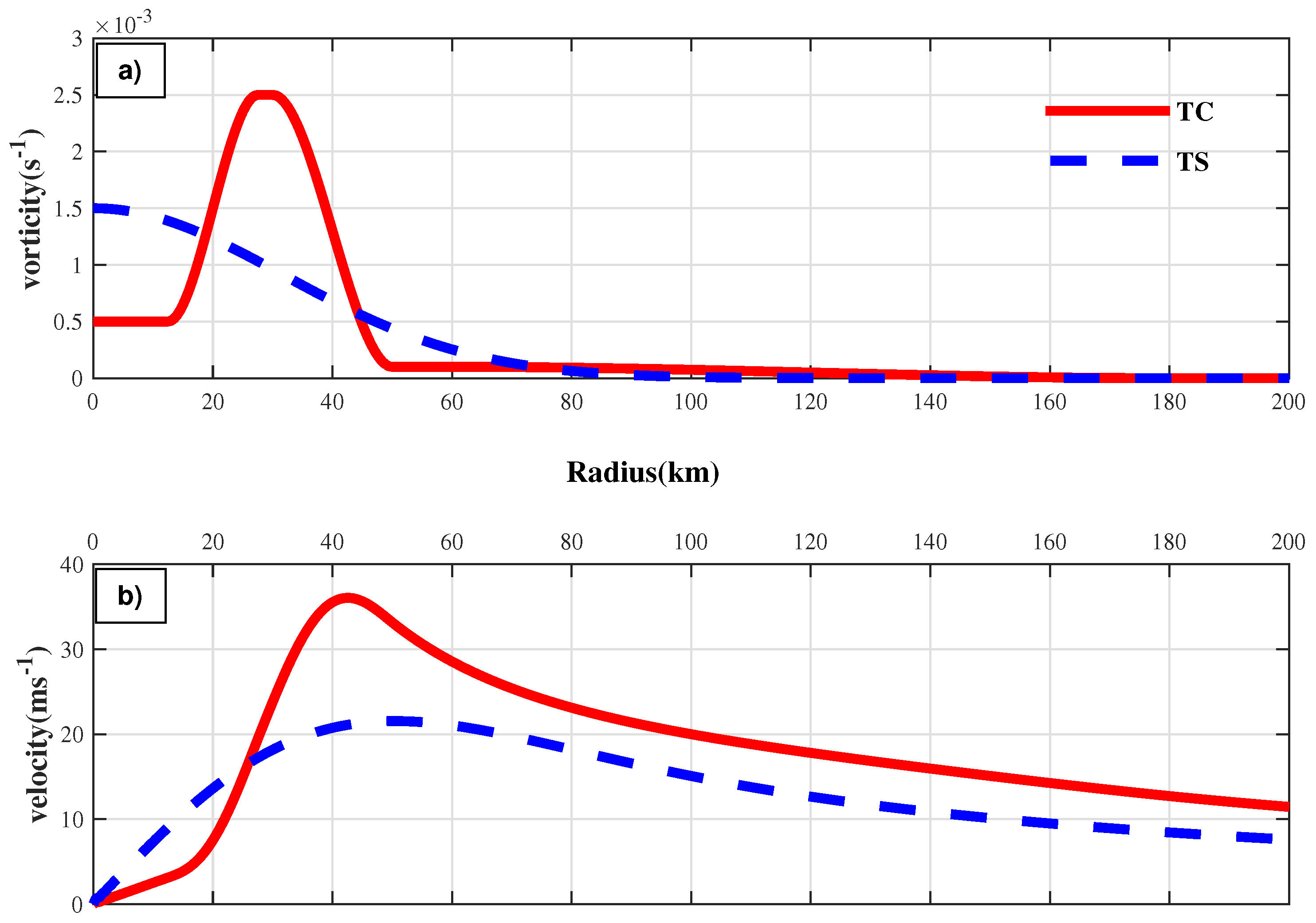
Two types of vorticity-based profiles were used to construct the symmetric idealized vortices in cases where a symmetric tangential wind profile was desired. With the aim of representing a hurricane-like vortex, the first profile was constructed by smoothly connecting radial intervals of constant vorticity with relatively low values at the eye and the highest value at the eyewall annulus. This profile was used to generate a Rankine-like vortex in previous studies [14,17]. The formula is described in Equation (1).
ζ ¯ ( r ) = ζ 1 0 r r 1 d 1 ζ 1 S [ ( r r 1 + d 1 ) / 2 d 1 ] + ζ 2 S [ ( r 1 + d 1 r ) / 2 d 1 ] r 1 d 1 r r 1 + d 1 ζ 2 r 1 + d 1 r r 2 d 2 ζ 2 S [ ( r r 2 + d 2 ) / 2 d 2 ] + ζ 3 S [ ( r 2 + d 2 r ) / 2 d 2 ] r 2 d 2 r r 2 + d 2 ζ 3 r 2 + d 2 r r 3 d 3 ζ 3 S [ ( r r 3 + d 3 ) / 2 d 3 ] r 3 d 3 r r 3 + d 3 0 r 3 + d 3 r
S ( x ) = 1 3 x 2 + 2 x 3 is the cubic Hermitian polynomial, which satisfies S ( 0 ) = S ( 1 ) = 0 and S ( 0 ) = S ( 1 ) = 0 . Values for each of the ζ i , r i , d i , r i , and d i can be changed to represent a hurricane-like vortex with a variety of strengths and various distributions. The settings for the parameters of a hurricane-like vortex of category 1 or category 3 on the Saffir–Simpson Scale can be found in previous work [14]. As the two vortices generated by Equation (1) in the literature share a similar ring-like distribution of vorticity, the category-1 profile was chosen to represent the hurricane-like vortex, hereafter called “TC”, that will be used throughout this paper. The TC vortex has a maximum wind speed of 36.0 m s−1 and an RMW of 42.5 km.
To represent a tropical storm-like vortex, the second profile was constructed with the Gaussian vorticity distribution shown in Equation (2). The highest vorticity was located at the eye of the vortex, and it decreased along the radius.
ζ ¯ ( r ) = A · e x p [ ( r b ) 2 ]
A vortex was constructed with a maximum wind speed of 21.5 m s−1 at a radius of 49.0 km, when A and b were set as 1.5 × 10⁻³ s−1 and 45 km, respectively. This vortex hereafter will be called “TS”.
The vorticity and velocity distributions of the TC and TS profiles are shown in Figure 1. The significant difference between the two profiles is that the gradient of vorticity changes its sign in the TC case.
Where needed, the symmetric radial wind is presented by the lognormal function profile described in Equation (3), which is similar to that used in Ry16.
U ¯ ( r ) = U m a x r e x p { s t 2 2 [ ( ln r s ) 2 2 t 2 ] }
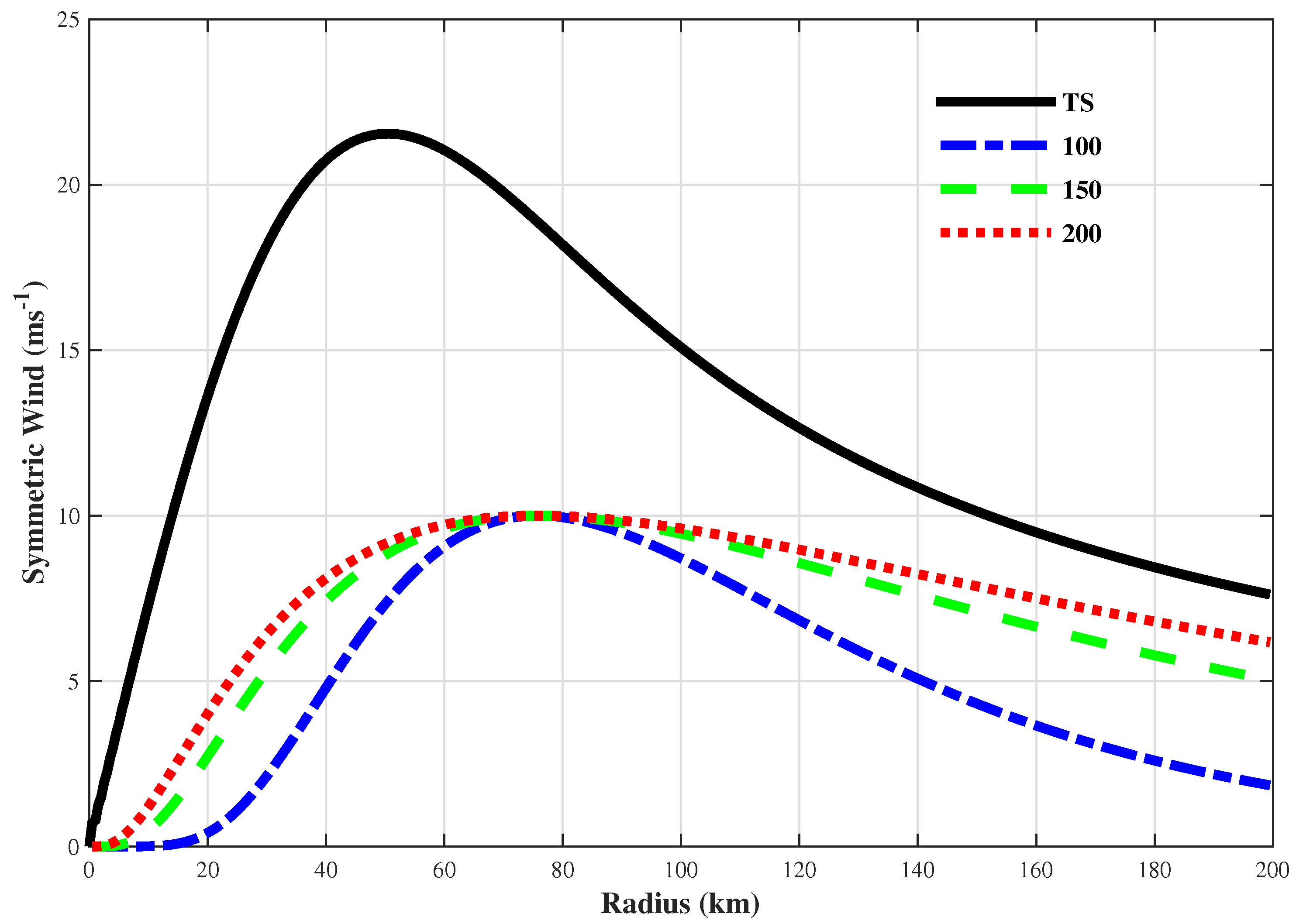
U m a x is the maximum radial wind. s and t are parameters deciding the distribution of the wind profile. The objective of using this simple parameterization is not to describe every detail of the azimuthal mean radial wind in real cases. Therefore, the peak of the radial wind is assumed to be at 1.5 RMW, from Ry16. Figure 2 illustrates the radial wind profiles with different values of s, where the parameter t equals 1.5 RMW.
All parametric profiles of the symmetric tangential and radial winds were initialized on a high-resolution cylindrical grid, which was 1 km in radius and π / 360 in radians. Once initialized, the fields on the cylindrical grid were interpolated onto a Cartesian grid using a bi-cubic interpolation. The Cartesian grid was set as 1 km in space to emulate the finer structure of tropical cyclones. The tangential and radial winds were also transformed into Cartesian winds. It was on this Cartesian grid that the center was displaced along a certain aliasing direction relative to the true center. According to Ry16, the divergence of center-finding algorithms is approximately 0.3 RMW and the aliasing error increases with the increase in center displacement. Therefore, 0.5 RMW was chosen as the largest aliasing distance to mimic further details of the aliasing asymmetries in most of our cases. For this study, 51 different centers (hereafter, potential centers) were chosen, which included the true center and 50 other evenly spaced intermediate centers between the true center and the largest aliasing distance. At each potential center, the Cartesian grid was interpolated back to a cylindrical grid using a bi-cubic interpolation to analyze the characteristics at low wavenumbers.
A uniform flow was directly initialized in the Cartesian grid in cases where uniform flows were needed. The sensitivity analyses on this uniform flow were mainly focused on the strength and direction of the flow relative to the aliasing direction.
In the cases with isolated asymmetries, a few more steps were needed because the asymmetries were defined as Gaussian-type perturbations of the streamfunction given by Equation (4):
ψ ( r , λ ) = A e x p [ ( r b ) 2 2 c 2 ] cos [ n ( λ φ ) ]
where A is the wave amplitude and b is the radial location of asymmetries relative to the vortex center. c, n, λ , and φ represent the radial width, wavenumber, azimuth angle, and wave phase, respectively. Before the asymmetries were added, the symmetric vortex was first converted into the streamfunction by inverting the relationship ζ ¯ ( r ) = ψ ¯ ( r ) . The distribution of ψ ¯ in the prescribed high-resolution cylindrical grid was numerically computed by supposing the streamfunction at the outer boundary to be 0. Then, the full wind and vorticity were calculated from the total streamfunction filed, including both ψ ¯ and ψ , by solving a Laplace equation. Symmetric vorticity and wind were removed from the full fields to isolate the asymmetric fields. Once initialized, the fields on the cylindrical grid were interpolated onto the Cartesian grid. This procedure was used to initialize the isolated nondivergent asymmetries.
A realistic vortex (TCA) was also constructed with an idealized Rankine vortex (TC case) and randomly generated nondivergent asymmetries to test the sensitivity of the center’s location on the wave–mean interactions around the RMW. The parameters controlling the radial location, and the range and strength of Gaussian-type asymmetries were chosen arbitrarily under certain restrictions. The restrictions for each of these parameters are listed in Table 1. For simplicity, only the winds and vorticity were used in the diagnostic equations given below. Figure 3 shows the initialized perturbations and the details of the randomly generated asymmetries. The potential centers shifted from west to east and cross the true center. In this case, the largest displacement was set to 4 km on both sides, which was approximately 0.1 RMW of the TC case. Five potential centers were uniformly spaced over the 8-km line.
In Ry16, the maximum wave amplitude ( V a l u e m a x ) along the radius was used as an index to evaluate the increase of low-wavenumber asymmetries. In this study, a new index, which is the ratio of the maximum wave amplitude and the mean value ( R a t i o m a x ), has been proposed to demonstrate the significance of the asymmetries. Another new index, namely the aliasing wave energy ratio (AWER), has also been proposed to indicate the variation of wave energy within a certain radius (three times the initial RMW).
A W E R ( j w , i n i w ) = 0 3 R M W i n i t E w a v e L d i s p ( j w , r ) 0 3 R M W i n i E w a v e 0 ( i n i w , r )
E w a v e ( n , r ) is the wave energy of wavenumber n at radius r. j w and i n i w represent a certain wavenumber and the wavenumber of the initial perturbation, respectively. Wave energy is defined as the square of wave amplitude (A). Moreover, the superscripts 0 or L d i s p represent the distance of the potential center from the initial center. This AWER was proved to be a useful tool in explaining the wave energy dispersion due to center displacement. Moreover, a derivate index ( A W E R W ) was constructed by replacing E w a v e 0 ( i n i w , r ) in Equation (5) with E w a v e L d i s p ( i n i w , r ) to evaluate the significance of each wavenumber. A W E R W is 1 when the j w equals i n i w . When j w equals i n i w , the higher the A W E R W , the more significant the asymmetries at wavenumber j w .
The wave–mean interactions were evaluated by the angular momentum equations. The tendency equations of the azimuthal mean tangential wind and radial wind are shown in Equations (6) and (7), respectively.
V θ ¯ t + V r ¯ V θ ¯ r + V r a V θ a r ¯ + V θ a r V θ a θ ¯ + V θ ¯ V r ¯ r + V r a V θ a ¯ r + f V r ¯ = 1 r ρ a P a θ ¯
V r ¯ t + V r ¯ V r ¯ r + V r a V r a r ¯ + V θ a r V r a θ ¯ V θ ¯ 2 r V θ a 2 ¯ r f V θ ¯ = 1 ρ ¯ P ¯ r 1 ρ a P a r ¯
V r ¯ and V t ¯ represent the azimuthal mean of radial wind and tangential wind, respectively. The asymmetric variables are denoted by subscripts. The first term in both the equations is the local tendency of the azimuthal mean wind. The second is the radial transportation by azimuthal mean radial wind (MRT). The third and fourth terms are the wave–mean interaction terms, representing the conversion of asymmetric wind to azimuthal mean wind by the asymmetric radial (ART) and tangential (ATT) wind, respectively. The following two terms are centrifugal force terms by the mean wind (MCT) and the asymmetries (ACT), respectively. The last term on the left is the Coriolis force term by the azimuthal mean wind (MCF). On the right side of the two equations are the gradient force by the pressure. Except for the local tendency terms in which there is no initialization for the pressure fields and time series of wind fields, the rest of the terms on the left-hand side of the two equations were calculated.

3. Results

3.1. Symmetric Tangential Wind

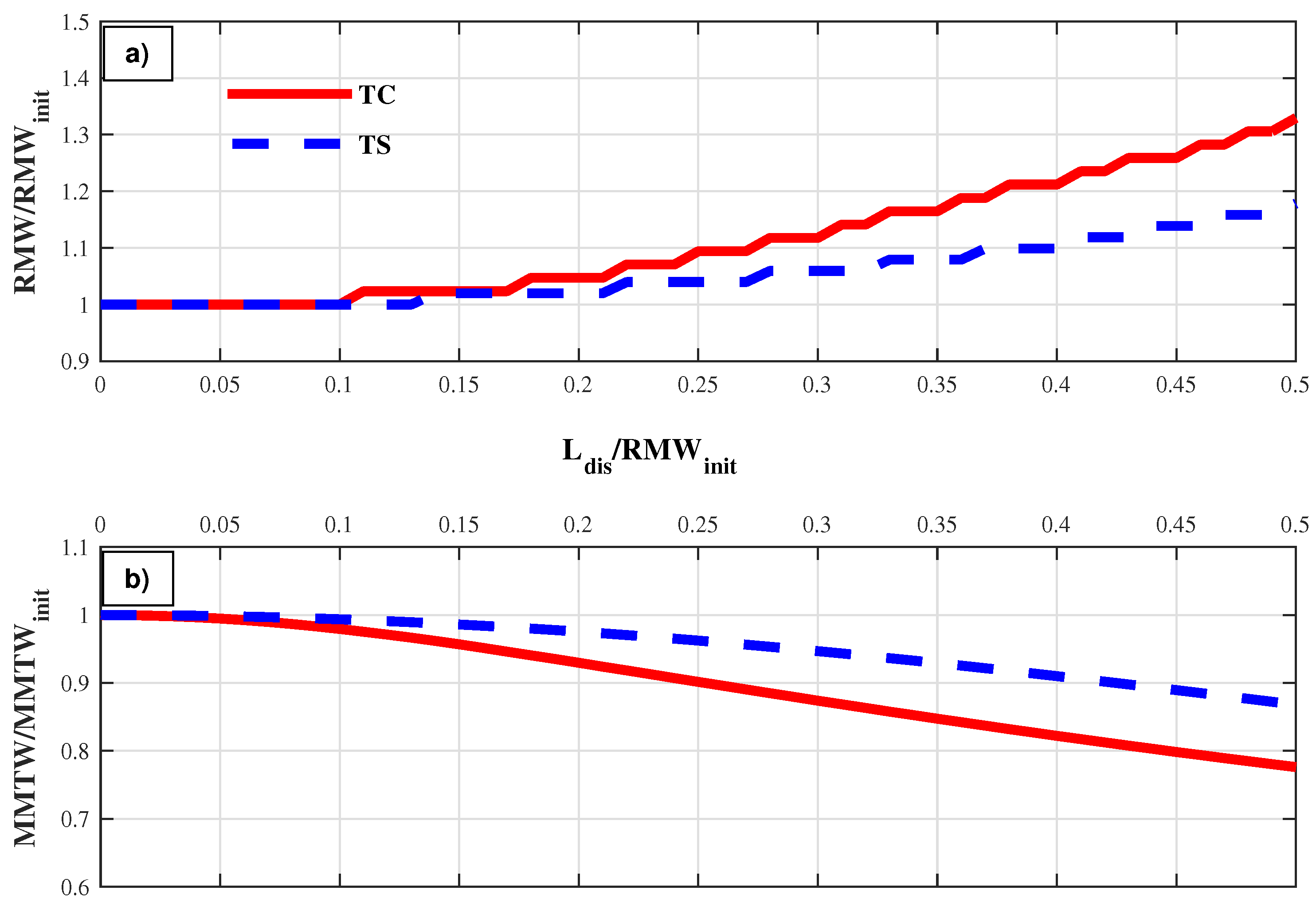
First and foremost, the basic behavior of an aliasing center on the primary circulation of a cyclonic vortex was analyzed by shifting the centers in the TC case and the TS case 0.5 RMW eastward. Figure 4 illustrates the normalized changes of RMW and MMTW. In both the cases, the RMW expands as the center displacement increases, while the MMTW decreases. The decrease in MMTW is much more gradual than that in RMW, indicating that the MMTW is less sensitive to the center location, which is in agreement with the findings of Ry16. The normalized deviations in both RMW and MMTW are much smaller in the TS case, indicating that the displacement of thet center’s location has a larger effect on a hurricane-like vortex (mature typhoon) than on a storm-like vortex. Sensitivity tests on the resolution of the Cartesian grid were also carried out (not presented in this manuscript), and the conclusions remain the same. Moreover, the decrease of MMTW was much smoother than the expansion of RMW in a coarser Cartesian grid.
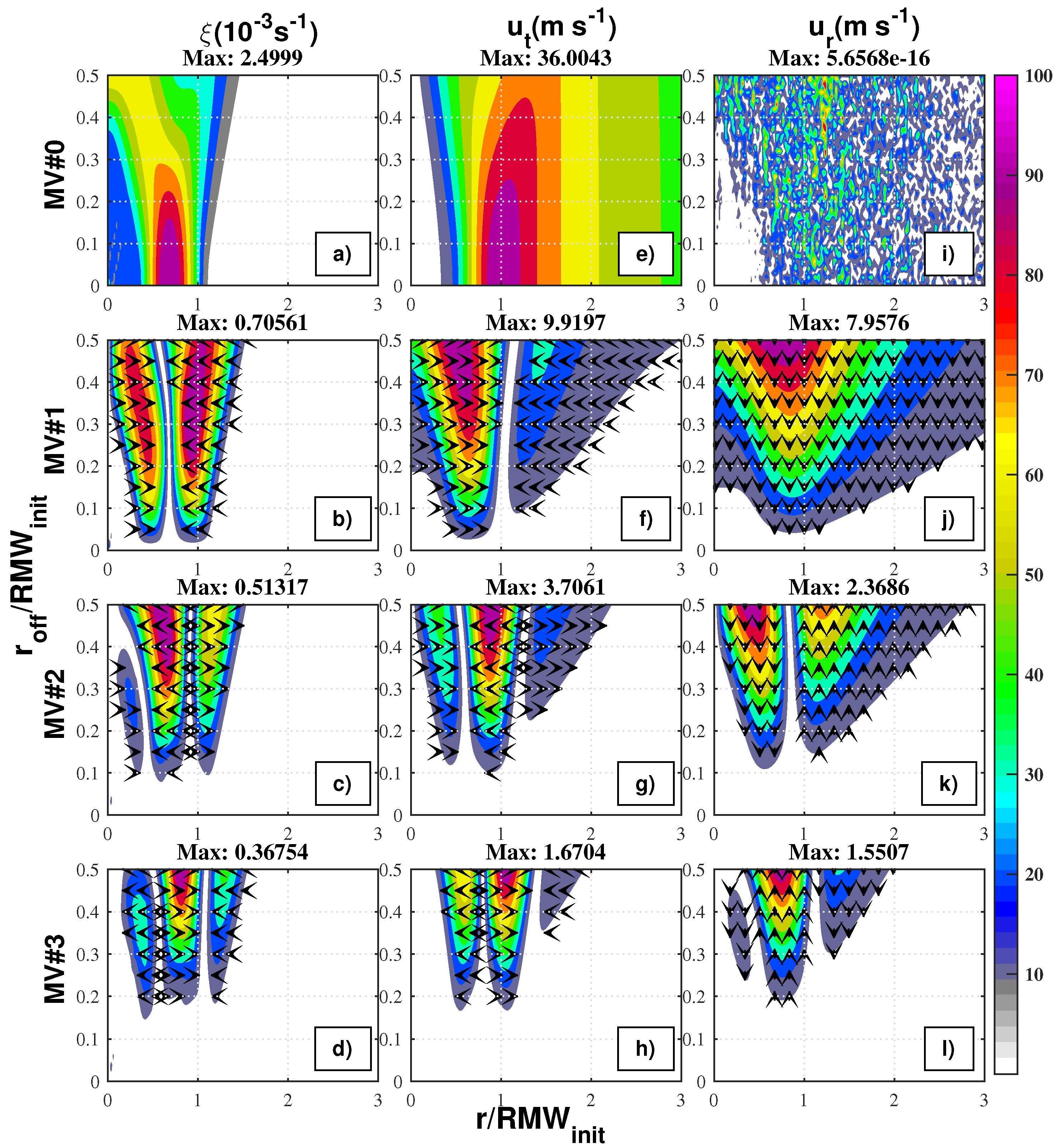
To further explore the aliasing asymmetries, the “postage stamp” presenting the normalized Fourier amplitude error profiles of vorticity, tangential wind, and radial wind used by Ry16 was updated by adding phase information to each radius. Phases at wavenumbers 1 to 3 are represented by black arrows. An eastward arrow indicates there is a positive wave peak located east of the original vortex. The phases are not displayed where the wave amplitude is less than 5% of the largest amplitude to emphasize the primal asymmetries. This new aliasing error profile is found to be a useful tool for illustrating the spatial distribution of asymmetries.
Figure 5 is the new “postage stamp” of the TC case. The symmetric mean vorticity is significant inside the RWM. The MMTW decreases and shifts outward, accompanied by the expansion of RMW with the increase in the offset. Meanwhile, the tangential wind at the inner radius increases gradually. These are in good agreement with the conclusions drawn from Figure 4. The high-value center of the azimuthal mean vorticity tends to decrease in amplitude and shifts inward. The azimuthal mean radial wind exhibited artificial noise (on the order of 10−16 m s−1), indicating that it was not altered by the symmetric tangential wind with a center aliasing error. This noise feature in the symmetric radial wind is briefly explained by Equation (A1) in the Appendix A section.
Focused on the aliasing asymmetries of vorticity, aliasing error profiles at each wavenumber (Figure 5b–d) were carefully examined. Two pieces of significant asymmetries were located, both on the inside of the RMW and at the inner radius of wavenumber 1 in Figure 5b. The outer piece had a larger wave amplitude than the inner one at the same offset. As the potential center moved, the high-value centers at the inner and outer radii shifted inward and outward, respectively. This distribution of aliasing profiles at wavenumber 1 is called “dual lobes” in Ry16. For higher waves such as wavenumbers 2 and 3, there existed three high-value lobes along the radius with the maximum amplitude located at the middle.
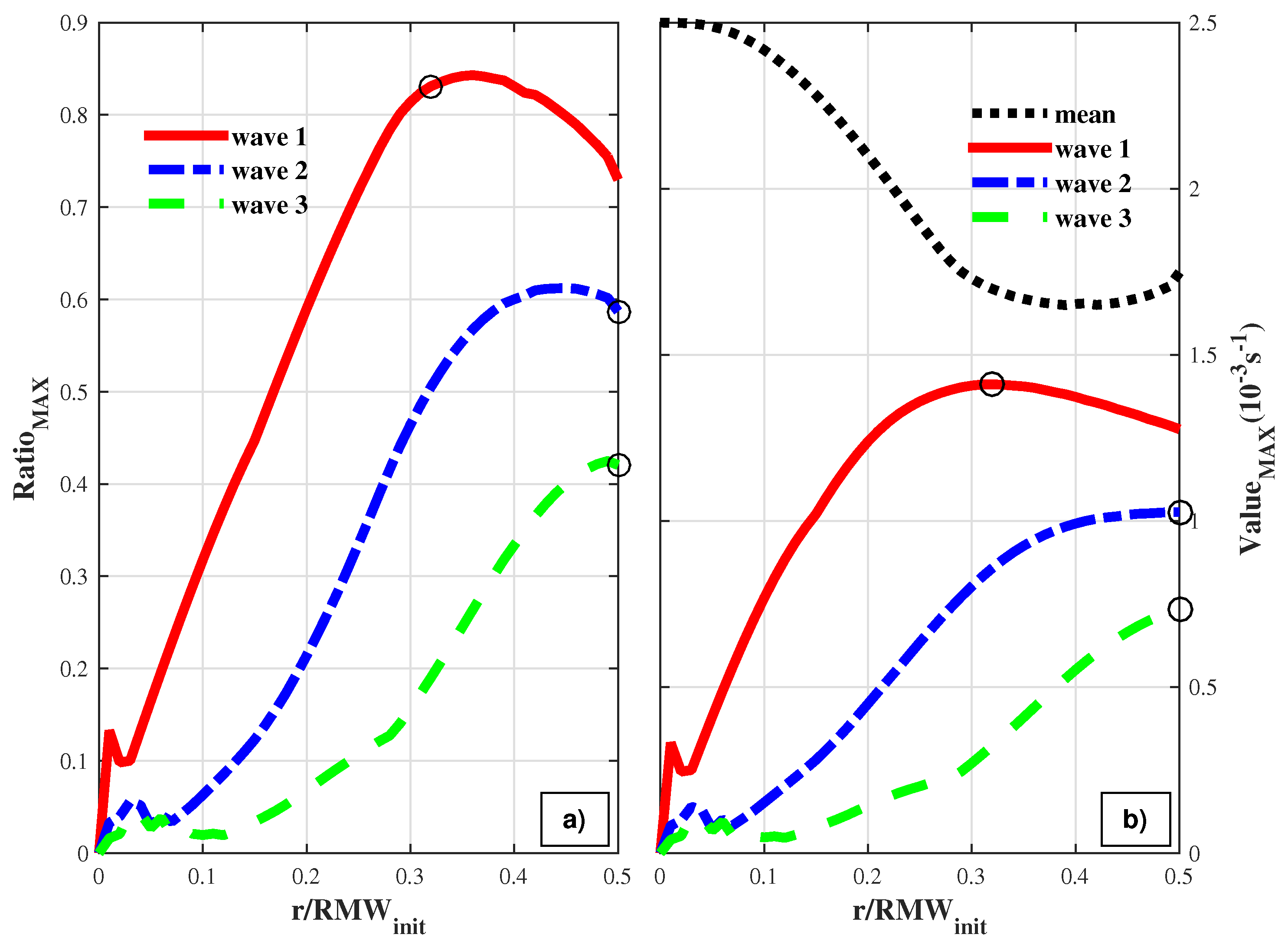
Figure 6 illustrates the changes of the R a t i o m a x and V a l u e m a x with respect to the increasing center offsets. The maximum wave amplitudes (all 10−3 s−1) of an asymmetric vorticity at wavenumbers 1 to 3 are 1.41, 1.026, and 0.75 when the offset is 0.32, 0.5, and 0.5 RMW, respectively. The R a t i o m a x of wavenumber 1 exceeds 0.8 at 0.3 RMW, and that of wavenumber 2 exceeds 0.5 at the same offset. This proves the aliasing asymmetries do play important roles in the vorticity fields. Moreover, the maximum value of wave amplitude at the wavenumber 1 vorticity decreases at a larger offset, while those at wavenumbers 2 and 3 increase. By extending the center offset to 1.0 RMW, the maximum amplitude at wavenumbers 2 and 3 are achieved at 0.56 RMW and 0.8 RMW, respectively. In other words, the asymmetries of vorticity at lower wavenumbers grow faster when the offset is small.
The spatial structures of aliasing vorticity asymmetries are also shown clearly in Figure 5b–d, along with information on wave phases. There are only two phases (0° and 180°) in the aliasing profiles at wavenumbers 1 to 3. For example, there is a triple-lobe distribution of aliasing vorticity asymmetries at wavenumber 2 (in Figure 5c). The wave phases are 0° at the inner lobe before turning to 180° at the middle lobe and reverting to 0° at the outer lobe. It is interesting to note that the phases remain constant in a single lobe and alter by 180 degrees between two adjoint lobes. In other words, the aliasing vorticity asymmetries encased by symmetric vorticity are non-tilting along the radius, and the positive and negative peaks are located in the same direction. It can also be concluded that the phases of aliasing vorticity asymmetries in the vorticity are parallel to the aliasing direction at any wavenumber.
The aliasing error profiles of wave amplitudes in both tangential and radial winds are similar to those in Figure 9 in Ry16 [32]. Therefore, attention is paid to the radial structures of aliasing asymmetries. The phases of the tangential wind are parallel to the 0°–180° line at any given wavenumber and offset. The wave phases switch 180 degrees at the radius, where a minimum wave amplitude occurs. Meanwhile, the phases of radial wind are perpendicular to the line. In other words, the phases of aliasing radial wind are always parallel to the aliasing direction and perpendicular to those of the tangential wind. There is no tilting in the aliasing asymmetries of either tangential or radial winds as the wave phases maintain their direction within each lobe.
Based on the above discussions, it can be concluded that aliasing asymmetries of vorticity, tangential wind, and radial wind fields are highly sensitive to the aliasing direction in the TC case. The aliasing asymmetries induced by a symmetric vortex constructed by the tangential wind only are non-tilting along the radius, with positive and negative peaks located in the same direction.
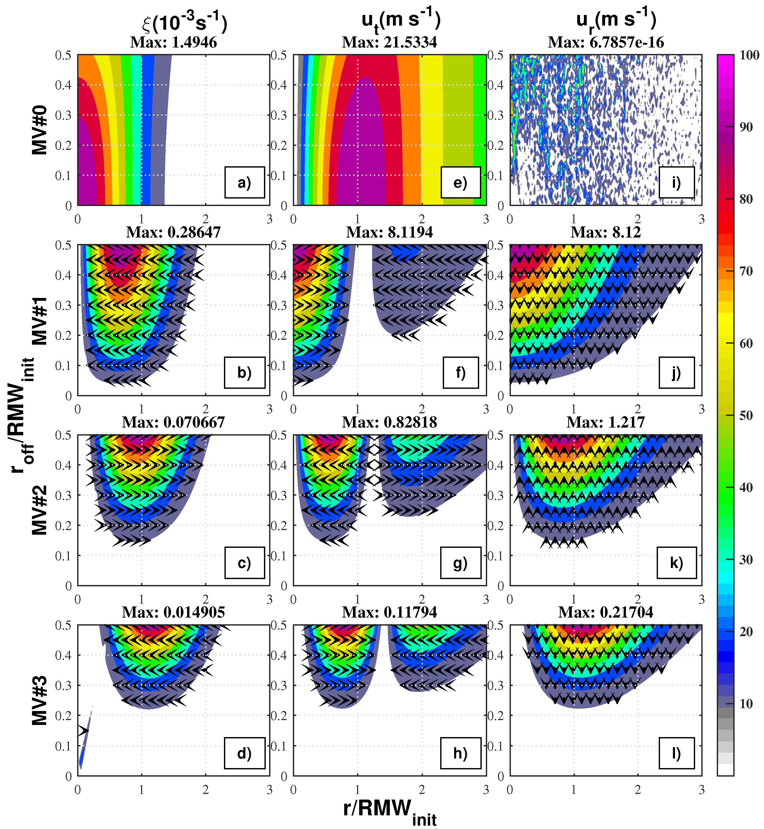
Figure 7 is the new “postage stamp” of the TS case. Significant differences exist in the distribution of aliasing error profiles at low wavenumbers in the vorticity fields. The maximum value of the mean vorticity is always located at the center (Figure 7a), except in the TC case where it shifts inward (Figure 5a). There is only one lobe along the radius in the aliasing profiles of the vorticity at wavenumbers 1 to 3, except for the dual lobes in the TC case. The maximum amplitude at each wave increases monotonically with the offset, except at wavenumbers 1 and 2 in the TC case, where it decreases. Although the wavenumber-1 vorticity asymmetries are primal in the TS case, the aliasing asymmetries in the TC case are more significant at the same offset. For example, when the center displacement is 0.3 RMW in the TS case, the R a t i o m a x at wavenumber 1 is 0.3, while being above 0.8 in the TC case. Therefore, the aliasing error of vorticity is less significant in terms of strength and simpler in radial structure in a storm-like vortex than in a mature hurricane.
It should also be noted that the phases of vorticity asymmetries in the TS case share similar characteristics with those in the TC case. By factoring in the tangential and the radial wind, asymmetry phases at each wavenumber that are parallel to the aliasing direction remain consistent within a single lobe and always turn 180 degrees at the boundaries of the lobes, indicating that the asymmetries are not tilted along the radius.
By considering the wave phases, the radial structures of aliasing asymmetries are carefully examined in this section. The most interesting findings are that the peak of aliasing vorticity asymmetries is parallel to the aliasing direction and that the aliasing asymmetries are non-tilting along the radius. As the discussions are based on an idealized symmetric vortex constructed by the tangential wind only, the symmetric radial wind alone will be addressed in the following subsection.

3.2. Symmetric Radial Wind

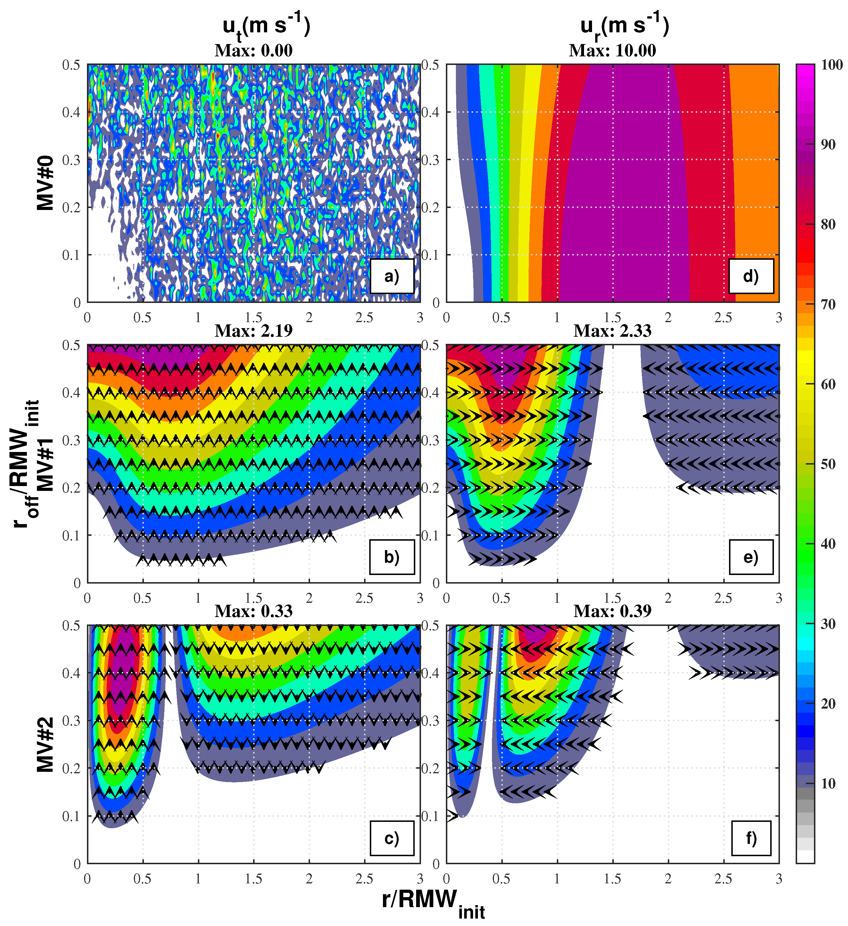
Although a strong symmetric radial flow is not relevant at the mid-levels of a mature cyclone, it is certainly important at lower and higher levels. The radial winds combined with vertical upward flows comprise the secondary circulation. First, the aliasing error profiles of a symmetric radial wind case (hereafter, IN) were illustrated. Then, the symmetric tangential wind of the TS case was added to analyze the aliasing asymmetries in a more realistic vortex (hereafter, TSIN). The initial profile of the symmetric radial wind was chosen by setting S to 150 km and U M a x to 10 m s−1.
Figure 8 illustrates the aliasing error profiles of the tangential and radial winds at low wavenumbers. The RMRW extends slowly as the center is offset, while the MMRW decreases (Figure 8d). The azimuthal mean of radial wind at the inner core of the cyclone increases slightly at the same time. It stands to reason that the RMRW is slightly more sensitive to the aliasing center than the MMRW is because the RMW is more sensitive than the MMTW. The azimuthal mean tangential wind has a noise signature, indicating that the symmetric radial wind does not affect the symmetric tangential wind regardless of the center’s location.
In the aliasing profiles of the tangential and radial winds at low wavenumbers, the asymmetries expanded in radius and strengthened in wave amplitude as the aliasing distance increased. There are two primal asymmetries in the radial wind at wavenumber 1—the one inside the RMRW and the one weaker in strength and located on the outer radius. The dual-lobe distribution in this case is similar to that of the tangential wind at wavenumber 1 in the TC case. Meanwhile, the wavenumber-1 asymmetries of tangential wind seem to be a single-lobe distribution and extend further in radius than those of the radial wind. An explanation for the inconsistency of the extending radius of asymmetries of the radial wind through Equation (A2) in both the TS and TC cases can be found in Appendix A. The aliasing error profiles at other wavenumbers seem to be either dual-lobe or triple-lobe distributions.
The wave phases remain constant within a single lobe and switch 180 degrees at the boundaries. This non-tilting characteristics of the aliasing asymmetries are consistent with those in the former section. The phases of aliasing radial wind are parallel to the aliasing direction and perpendicular to the tangential wind at the same time. The amplitudes of both tangential and radial wind asymmetries at wavenumber 1 grow faster than those at other wavenumbers. Therefore, the symmetric winds are likely to produce aliasing perturbations at wavenumber 1 when the center is slightly displaced. Sensitivity tests on parameter S have also confirmed these findings.
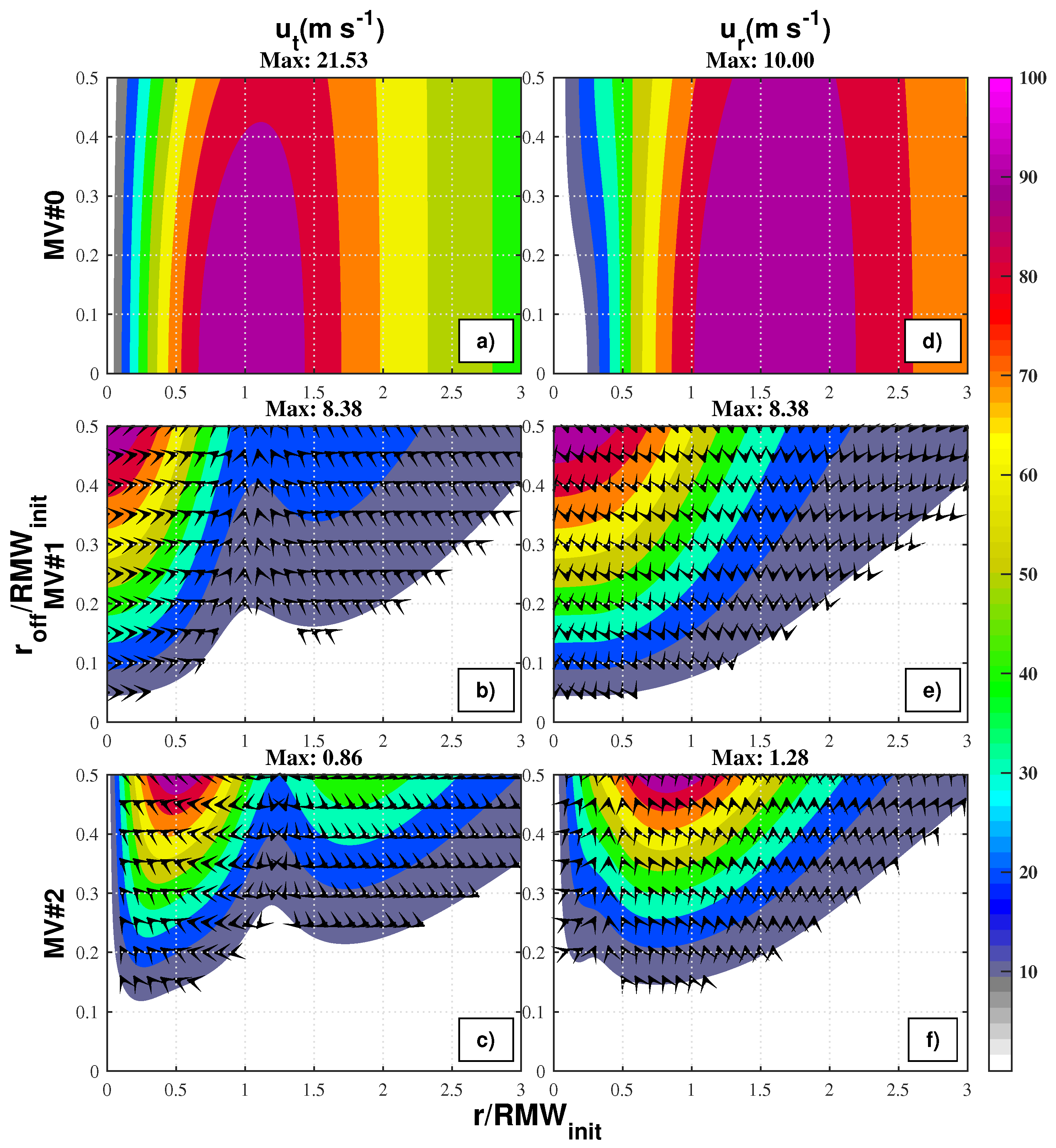
Figure 9 illustrates the aliasing profiles of the TSIN case. The wave amplitudes in the tangential and radial winds (Figure 9b,e) are not very different from those in the TS case (Figure 7f,j). For example, the aliasing asymmetries of the tangential wind at wavenumber 1 reaches its maximum value (m s−1) near 16.76 when the offset is 0.5 RMW, which is only 0.5 times greater than that in the TS case. The symmetric radial wind makes a limited contribution to the strength of the aliasing asymmetries in both the tangential and radial winds. It stands to reason that the tangential wind fields dominate the aliasing errors, as the symmetric tangential wind is much stronger than the radial wind. The phases of aliasing asymmetries within the lobes are parallel neither in the tangential wind nor in the radial wind. In other words, the aliasing asymmetries are tilted along the radius. For example, the aliasing tangential winds at wavenumber 1 are shifted anti-clockwise, especially when the center is slightly displaced. Moreover, the radial tilting of the tangential wind is more obvious than that of the radial wind. Therefore, besides having a less than significant impact on the wave amplitudes, the symmetric radial wind fields have a negligible influence on the radial structures of aliasing asymmetries.

3.3. Uniform Environment Flows

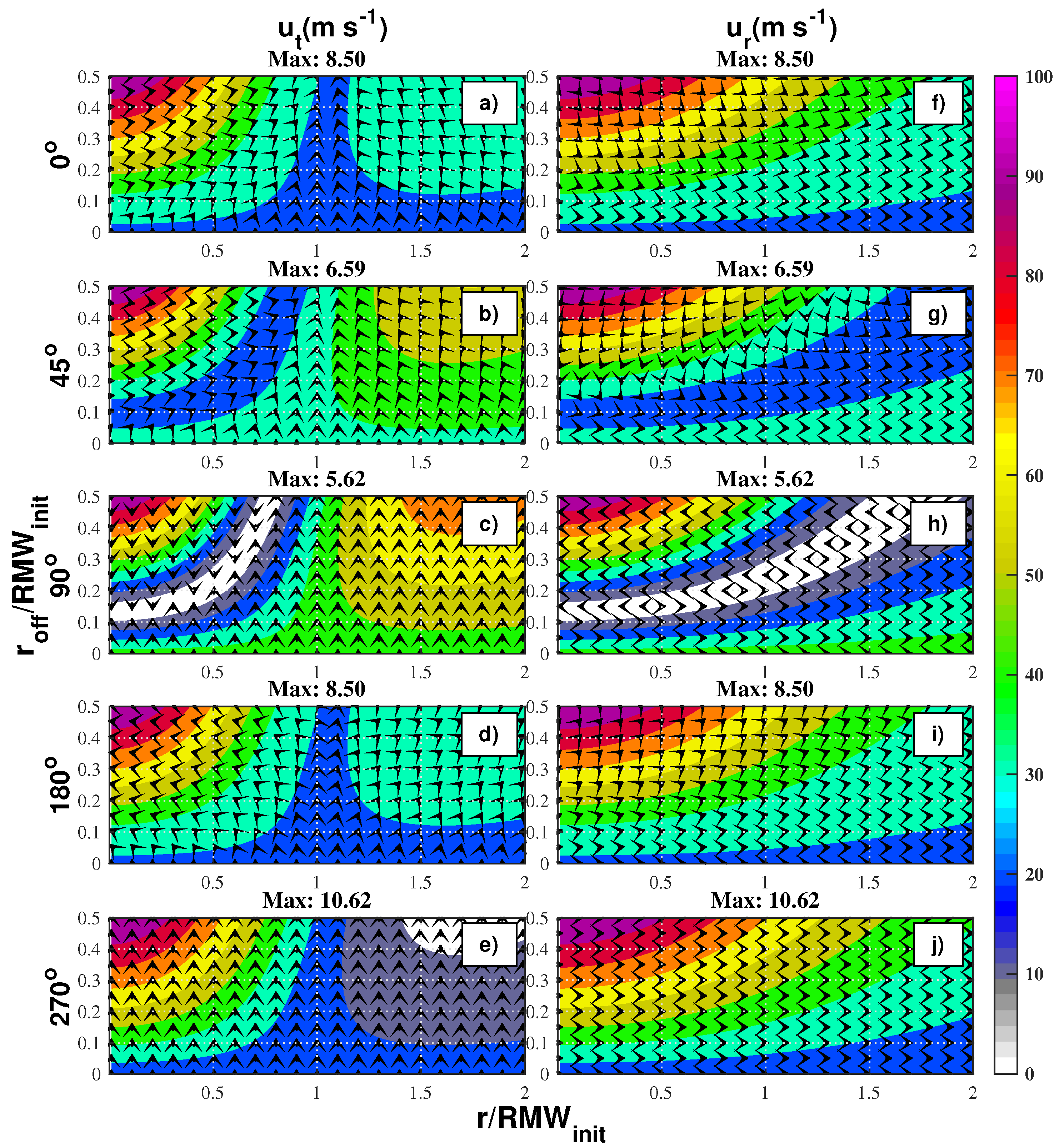
Environment flow is an important factor affecting the track and strength of TCs. The direction of convective asymmetries relative to environment flow was found to have a relationship with the intensity of a TC [33,34,35]. In this section, the influence of a uniform flow on the aliasing error profiles is examined by adding constant flow to the TS case (hereafter, TSE). Ten aliasing angles were chosen to illustrate the influence of the aliasing direction. The uniform flow is set 2.5 m s−1 eastward.
Figure 10 shows the aliasing error profiles of the TSE case in the tangential and radial wind fields in different aliasing directions. The aliasing direction affects the maximum wave amplitude of aliasing asymmetries. The aliasing wave amplitudes in both the radial and tangential wind fields increase to 2.5 m s−1, which equals the strength of environment flow when the aliasing direction is 270°. Meanwhile, the largest negative influence (−2.5 m s−1) is achieved once the aliasing direction is at 90°, compared to Figure 7f,j. The aliasing wave amplitudes of tangential and radial wind in the 0° case (Figure 10a,f) are identical to those in the 180° case (Figure 10d,i). Once the aliasing direction approaches 90°, the negative influence on the wave amplitude of aliasing asymmetries increases. This is in contrast to the case when the aliasing direction approaches 270°. The differences in aliasing asymmetries are more pronounced in their radial structures. For example, despite the wave amplitudes of the tangential wind in the 0° case being identical to those in the 180° case, a remarkable difference exits in the wave phases. The asymmetries of tangential wind in the 0° case have an anti-clockwise tilt. Meanwhile, those in the 180° case have a clockwise tilt. The aliasing error profile can be determined by the symmetric tangential wind with a certain aliasing direction and constant appendages induced by uniform flow.
Thus, it is confirmed that the aliasing error profiles are sensitive to the strength of uniform flow. However, it should be noted that the aliasing asymmetries are determined not only by the distribution of symmetric wind but also by the strength of the environment flow and the aliasing direction.

3.4. Isolated Asymmetries

Multi-scale convective systems embedded in the tropical cyclone circulations are represented by the azimuthal waves. As strength and radial structures are important for evaluating the wave–mean interactions, the aliasing error profiles of the asymmetries were investigated carefully. The symmetric tangential wind was removed after adding the initial asymmetries to isolate said asymmetries from other circulation systems. Therefore, only the vorticity and winds related to the initial asymmetries were kept in the Cartesian grid. According to Ry16, the aliasing error profiles are the same whether the aliasing direction is away from or close to the maximum of the asymmetric center. Once the center has moved along the zero contour of the asymmetries, the aliasing error profiles take on a different distribution. For a full understanding of the influence of aliasing direction, sensitivity tests were performed with a larger group of aliasing directions. More focus was given to the radial structure and the dispersion of wave energy.
Figure 11 shows the initialization of wavenumber 1 asymmetries centered at the RMW of the TC case (hereafter AS1). The vorticity is shaded and normalized with the maximum value (0.28 × 10⁻³ s−1). The divergence at each grid point is zero because the asymmetries are defined in streamfunctions. Therefore, the maximum positive and negative vorticity centers are surrounded by nondivergent flows. Similar distributions can be observed in the vorticity and wind fields initialized at a higher wavenumber but with more positive and negative centers located along the azimuthal direction. Ten different directions were artificially chosen for the wavenumber-1 asymmetries. The 0° and 180° angles indicate that the offsets were moved toward the positive and negative centers (peak line), respectively. Moreover, the 90° and 270° angles represent that centers moved along the zero contour of the vorticity field (middle-line) but in different directions. Other aliasing directions such as 30°, 45°, and 70° were chosen to represent a gradual change between a middle line and a center line. These directions were chosen based on their symmetric characteristics. For example, 70° and 110° are symmetric to the middle line. The aliasing directions at other wavenumbers were chosen in the same way.
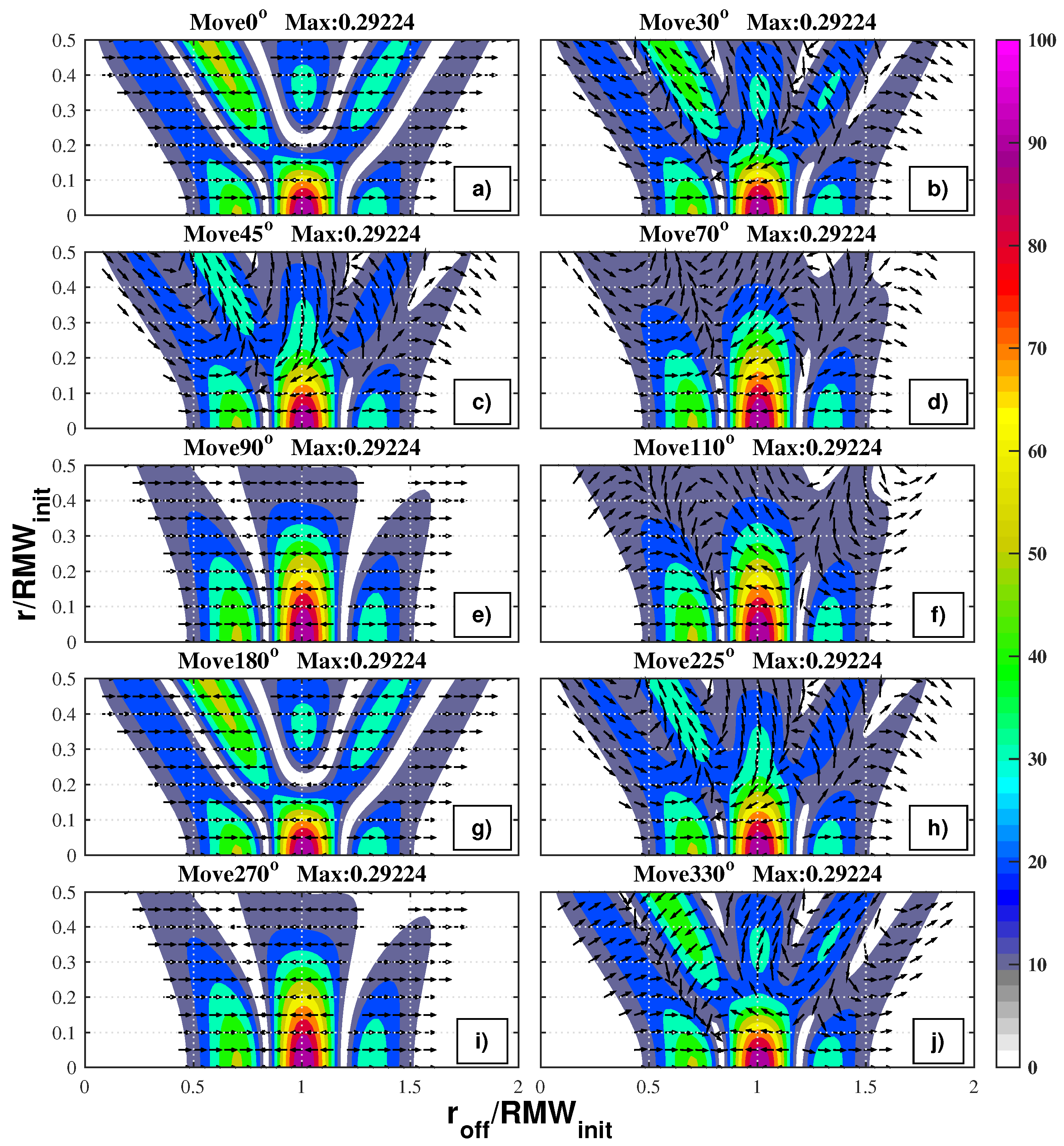
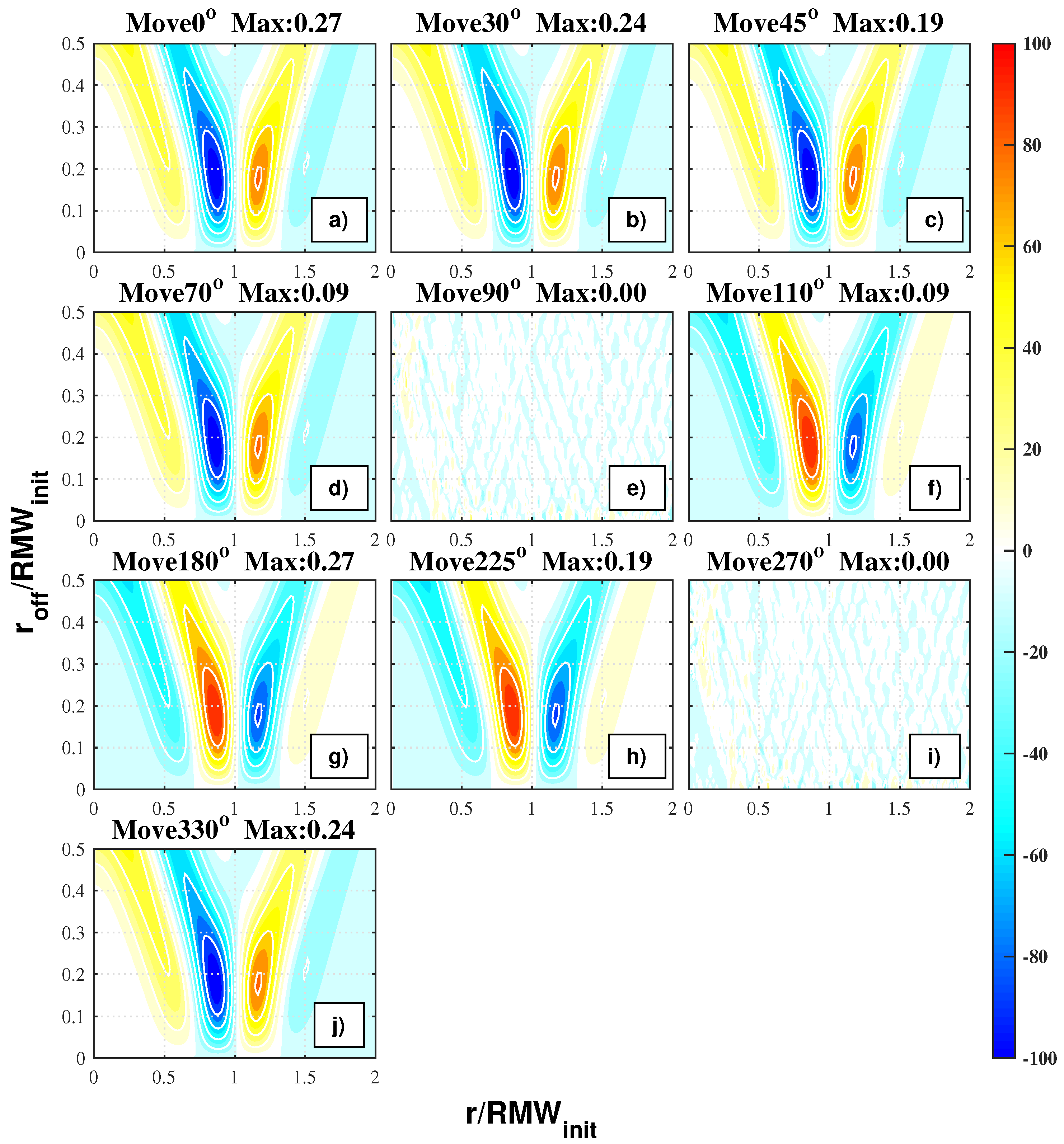
Figure 12 illustrates the aliasing error profiles of the vorticity at wavenumber 1 in different aliasing directions. The most noticeable feature is that, although the amplitudes of asymmetries decrease, the radial positions remain unchanged when the offset is less than 0.2 RMW. Meanwhile, there is a large inconsistency between different aliasing directions, especially at larger offsets in terms of the amplitude and phase.
The aliasing profile appears to be a triple-lobe distribution when the center has moved along a peak line (0° or 180°) and when the offset is less than 0.2 RMW. The strength of the wave amplitude decreases with the increase in the offset. The lobe in the middle trifurcates into three lobes, and the maximum value of the wave amplitude increases again with a growing offset (Figure 12a,g). Meanwhile, once the aliasing centers are on the middle line, the aliasing profile becomes a triple-lobe distribution (Figure 12e,i). The wave amplitude on the middle line decreases monotonically except when it experiences a regrowth in the peak line case. In agreement with the findings of Ry16, a large difference is seen in the wave amplitude of the aliasing profiles between the middle line case and the peak line case. With a focus on the radial structures of asymmetries, it is interesting to find out that there was no radial tilt within any single lobe once the center had moved along the middle line or the peak line (Figure 12a,e,g,i). The wave phases always turn 180 degrees at the boundaries. Therefore, not only the strength but also the radial structures of the aliasing asymmetries are identical once the two offsets are along the middle line or the peak line at the same displacement. It was also confirmed that the information loss in the initial asymmetries was more gradual when the aliasing direction was along the middle line than along the peak line.
The aliasing error profiles of wave amplitudes gradually shifted from the middle-line case to the center-line case once the center moved in the other directions. For instance, the distribution of wave amplitude in the 30° case (Figure 12b) was more similar to that in the 0° case (Figure 12a) than in the 90° case (Figure 12e). The aliasing error profiles were found to be identical in amplitude when the aliasing directions were symmetrical to a middle line (such as Figure 12d,f) or a center line (such as Figure 12b,j). The asymmetries in the radius were always tilted. Despite the wave amplitudes between the symmetric cases being identical, there was a significant difference in the tilting directions. For example, the inner lobe in Figure 12d has an anti-clockwise tilt, whereas, in Figure 12f, it has a clockwise tilt. In other words, the spatial structures of the aliasing vorticity asymmetries were more sensitive to the aliasing direction but not their strength.
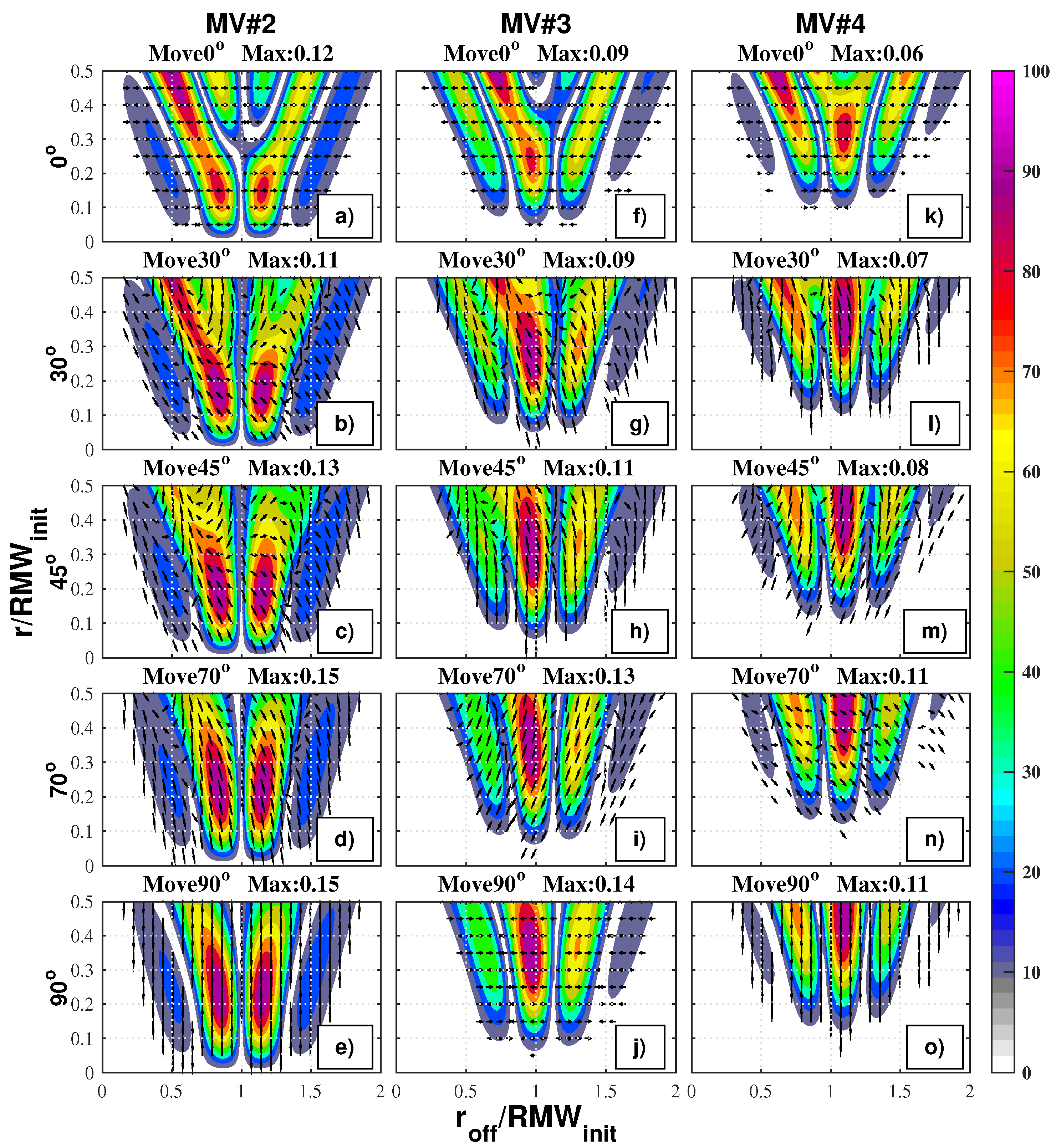
Figure 13 illustrates the mechanism of aliasing of initial wave onto other wavenumbers in different aliasing directions. Only parts of the cases are displayed to illustrate the sensitivity of wave dispersion to the aliasing direction because of the symmetric characteristics of the aliasing error profiles between two symmetric aliasing directions. The aliasing error profiles appear to be a cluster of lobes along the radius, extending outward or inward with the increase in offset. A large distinction lies in the aliasing profiles between a center-line (0°) case and a middle-line (90°) case at each wavenumber. The aliasing profiles in other directions also show a gradual transformation from the center-line case to the middle-line case.
The radial tilting of aliasing asymmetries is much more complex. For example, in the 30° case, there is an anti-clockwise tilt in the inner-most lobe and a clockwise tilt in the lobe inside the 1.0 RMW at wavenumber 2 (Figure 13b). Meanwhile, the tilt in the inner-most lobe is clockwise and becomes anti-clockwise in the outer lobe at wavenumber 3 (Figure 13g). However, there is no radial tilting within any lobe when the offset is along a middle-line (Figure 13e,j,o) or a peak-line (Figure 13a,f,k). Through a deeper exploration of the aliasing profiles, some symmetric characteristics were also discovered. The aliasing error profiles at wavenumbers 2 and 4 shared similar characteristics, different from those at wavenumber 3. Firstly, the phases at wavenumber 3 were parallel to those of the initial wavenumber 1 asymmetries when the center moved along the center line or middle line. The aliasing asymmetric phases were symmetric to the peak line of the initial asymmetries when two aliasing directions were symmetric to a center line or a middle line (not shown here). Secondly, for aliasing profiles at wavenumbers 2 and 4, the phases were perpendicular and parallel to initial phases when the aliasing directions were along a middle-line and a center-line, respectively. When two aliasing directions were symmetric to a middle-line or a peak-line, the aliasing phases were symmetric to the line as well.
For the aliasing error profiles of initial asymmetries at other wavenumbers, not only the wave amplitude but also the phases of the aliasing vorticity asymmetries satisfied all the symmetric characteristics discussed above. As there existed more than one peak along the azimuthal direction, neither the directions toward the positive and negative centers nor those along different middle lines were parallel. Therefore, the symmetric characteristics became stricter. Firstly, the phases were parallel along the radius when the offset was along a center-line or a middle-line, indicating that the aliasing vorticity asymmetries were not tilted. Meanwhile, the aliasing asymmetries were tilted along the radius in other directions. Secondly, the aliasing phases were symmetric to a peak line when the aliasing directions were symmetric to the line. If two aliasing directions were symmetric to a line perpendicular to a peak line, their wave phases were symmetric to the line as well.
The dispersion of wave energy is discussed because of its importance in the energy spectrum. Figure 14 shows the AWER of the AS1 case for different aliasing directions. It should be noted that the symmetric characteristics in the wave amplitude are reflected in the wave energy at each wavenumber, as is the gradual transformation of aliasing asymmetries in the vorticity. The wave energy decreases rapidly before the center is moved further than 0.2 RMW in the 0° and 180° cases at the initial wavenumber 1. Therefore, the energy loss is the greatest along the peak lines, which is consistent with the previous findings of the authors of this paper. The wave energy in the peak-line case increases after the trifurcation occurs. Meanwhile, the loss of wave energy appears to be a continuous attenuation in the middle-line cases. Even though the peak-line cases conserve more wave energy at the initial wavenumber, the radial structures of asymmetries have been completely aliased according to Figure 12a. At other wavenumbers, it is clear that more amounts of wave energy are distributed when the aliasing direction is along a middle line, especially when the displacement is small. For instance, the energy at wavenumber 2 in the middle-line cases is nearly twice that in the peak-line cases when the offset is at 0.25 RMW. The wave energy at wavenumber 2 appears to have gained more energy for the initial wavenumber 1 asymmetries than for other wavenumbers. The higher the wavenumber, the lower the aliasing wave energy gain.
The standard dispersion—defined as the ratio of the maximum difference between the AWER values among different directions and their mean value—were used to evaluate the potential dispersion of wave energy at each wavenumber. The standard dispersion shows that the dispersion of aliasing wave energy is smaller at larger wavenumbers. For example, when the center is erroneously positioned 0.2 RMW away, the standard dispersions are 0.82, 0.68, 0.47, and 0.35 for wavenumbers 1 to 4, respectively. After examining the error profiles from the asymmetries at other initial wavenumbers (not shown here), the aliasing error profiles for higher waves seem to be insensitive to the aliasing directions. The aliasing center prefers to distribute the wave energy to the adjoint wavenumbers, and the aliasing asymmetries at a smaller wavenumber gain slightly more energy.
Last but not the least, how the aliasing asymmetries affect the mean fields when the center is erroneously positioned is discussed. Figure 15 shows the aliasing errors in the azimuthal mean vorticity fields in different aliasing directions of the AS1 case. The changes appear to be pairs of positive and negative peaks around the radius where the maximum amplitude of the initial asymmetries is located. The influence at the inner side is slightly stronger than that at the outer radius. The signs are opposite despite the absolute changes being identical when the aliasing directions are symmetric to a middle line (Figure 15a,g). Meanwhile, the displacement of the center’s location would not change the mean vorticity fields when the center is along a middle line (Figure 15e,i). Moreover, when the aliasing directions are symmetric to a peak line, their changes to the mean vorticity field are identical. The maximum change of mean vorticity occurs when the center is moved along a peak line, as the loss of wave energy at the initial wavenumber is the largest. Therefore, asymmetries do affect the mean vorticity, and their influences are sensitive to the aliasing direction.
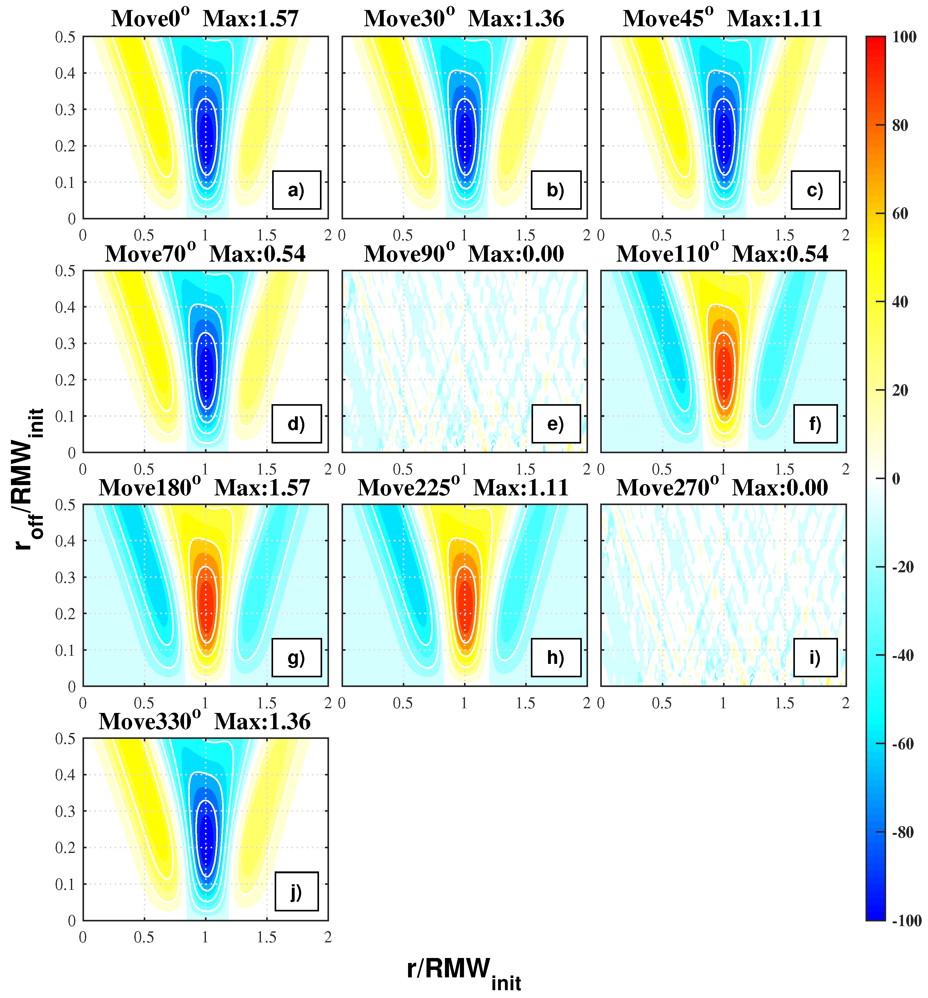
Figure 15 and Figure 16 are similar to each other except for the changes in the mean tangential wind fields. The mean tangential wind can be reduced or increased at the radius where most of the asymmetries are located. The changes at both sides of this maximum center are weaker and have the opposite signs. Similar symmetric characteristics in different aliasing directions are also found in the upscale influence on the mean tangential and radial winds fields as well (not shown here). The azimuthal mean fields can also be altered when an aliasing error is induced by the asymmetries at higher wavenumbers. Thus, the upscale influence decreases as the initial wavenumber increases. Therefore, it should be noted that aliasing asymmetries do influence the mean fields when the center is displaced. Moreover, the aliasing asymmetries could induce an error in the MAV algorithm as their convergence condition is to maximize the mean tangential wind once the asymmetries around the RMW become significant.
Sensitivity tests on the strength, location, and radial size of the initialized asymmetries were also performed. It was found that the radial size and strength of the initial asymmetries determined the radial distribution of the aliasing error profiles and controlled the absolute amplitude, respectively. The location of the center location of the asymmetries is an important parameter that decides the range of influence induced by the aliasing asymmetries.

3.5. Sensitivity Tests of Angular Momentum Equations

The increase in the azimuthal tangential wind at the RMW is considered the intensification of a tropical cyclone. Many scholars have used the tangential wind tendency equations to illustrate the key factor that dominates the intensification process. Sensitivity tests on the angular momentum equations were carried out using the TCA constructed in Section 2. The order of each tendency terms in Equation (7) is approximately (10−3 m s−2), except for the MRT and ART terms. The MCT term in the azimuthal mean radial wind equation is more significant. Meanwhile, the ART term dominates Equation (6) at an order of 10−4 m s−2. Terms including V r ¯ are negligible because the initial condition is set without any symmetric radial wind.
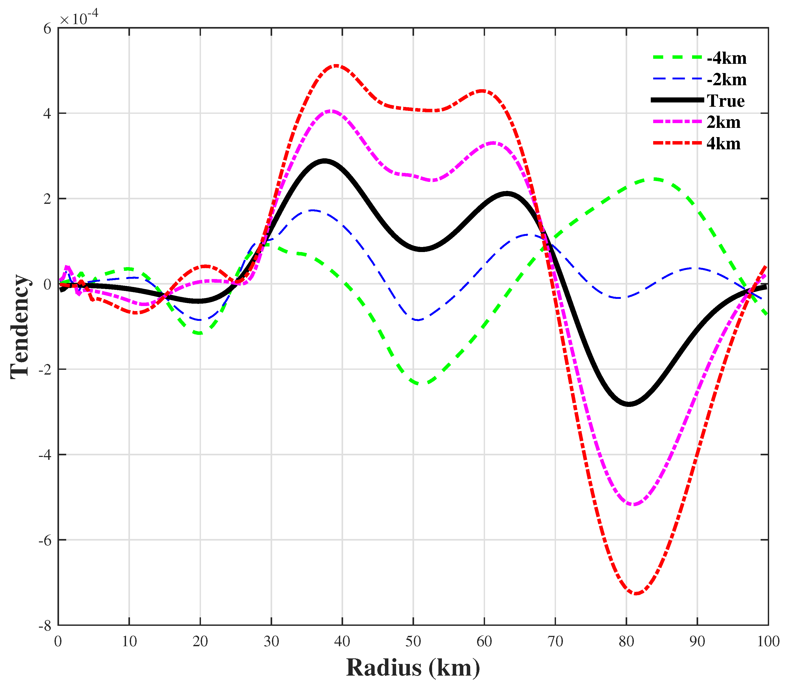
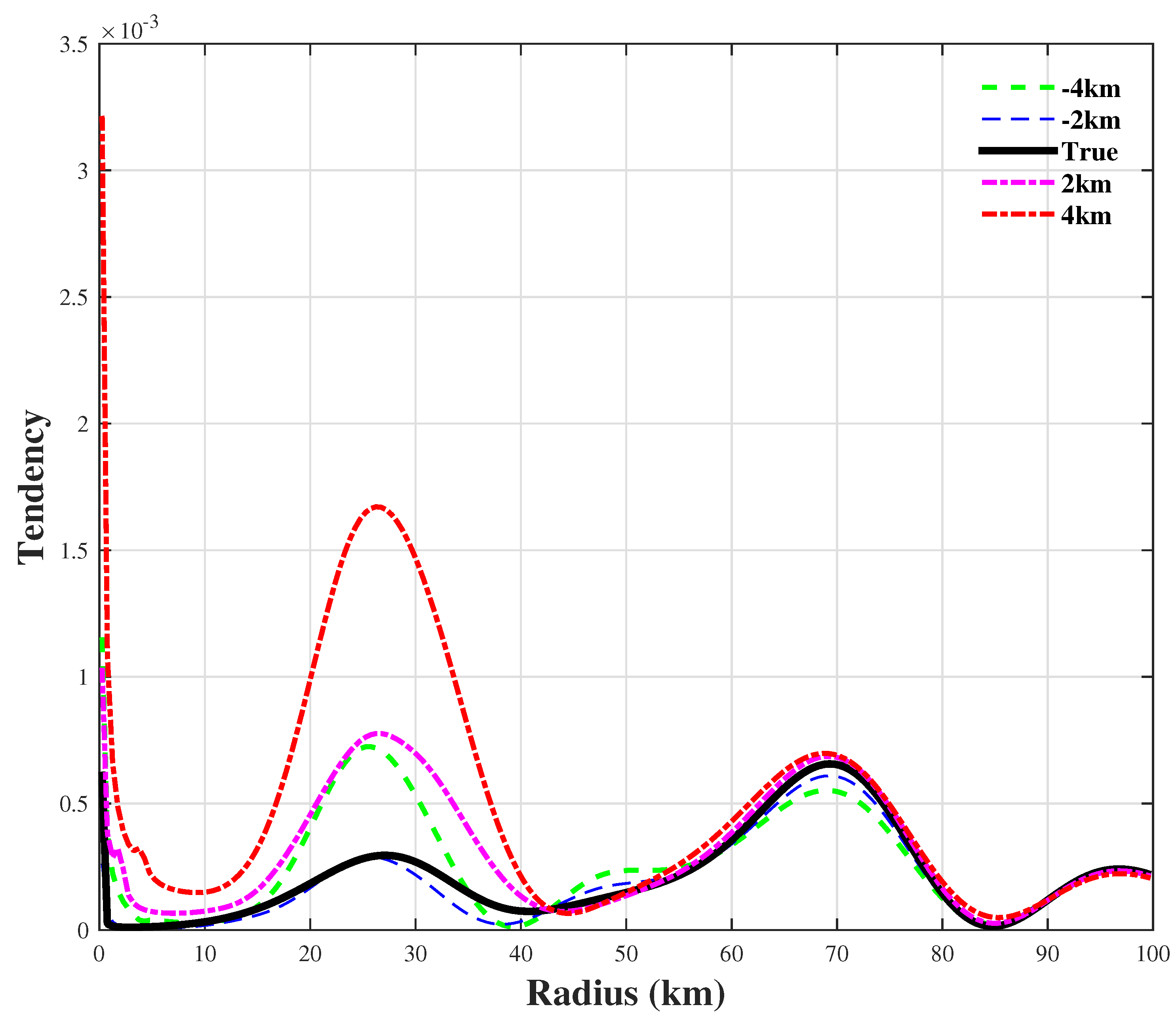
Focused on the wave–mean interaction terms in the tangential wind equation, the radial distributions of the ART are displayed in Figure 17. The ART has a small negative value at the inner radius. It has a positive influence over the range of 25 km to 70 km and a negative influence at the outer radius. This S shape of the ART is centered at 70 km, where the strongest asymmetries are located, according to Figure 3. The range of positive tendency fluctuates due to the existence of weaker asymmetries. In other words, there was a slight contraction and intensification of the azimuthal mean wind by the idealized asymmetries. Thus, the ART was doubled when the center was located 4 km to the west, indicating an overestimation of asymmetries. However, the influence of ART could be completely reversed when the offset was only 4 km to the east. The dominant “S” shape, which was centered at 70 km, has a negative influence at the inner radius and a positive influence at the outer radius, which represents the weakening and expansion of the tangential wind. The aliasing error in the ART becomes larger in magnitude with as the center displacement increases. Opposite wave–mean interactions can also be found in the radial profiles of the ACT term. Therefore, it is extremely important to know that the analysis on the wave–mean interaction is highly sensitive to the location of the center, especially to the aliasing direction relative to the true center.
Figure 18 shows the ACT in Equation (7). The initial asymmetries tend to increase the azimuthal mean radial wind. The positive influence by the dominant asymmetries centered at 70 km is more significant than the weaker asymmetries at the inner radius. The ACT at the outer radius is insensitive to the center location, leading to the conclusion that the radial structures of initial asymmetries could be preserved at a small displacement in the former section. Meanwhile, the ACT is altered severely at the inner radius. The positive tendency is doubled once the center is located only 2 km eastward. The aliasing error in the ACT also increases with the increase of the center displacement. Therefore, the ACT term is sensitive to the aliasing direction. Compared with the reversed contributions of the asymmetric flows in Equation (6), the contributions of the ACT term in Equation (7) are less sensitive to the location of the center. Moreover, the radial distributions of the other terms in Equation (7) change insignificantly in different aliasing directions, especially the MCF and MCT terms. Therefore, it can be concluded that the diagnosis of azimuthal mean radial wind is less sensitive to the location of the center and that the wave–mean interactions on the radial wind terms are more reliable than those on the tangential wind.
Although the conclusions are based on idealized experiments, they explain the disagreement on the role of asymmetric flows. A further verification of the robustness of related conclusions with the understanding of uncertainties in the diagnostic equations is needed.
4. Summary and Discussion

In this work, the potential aliasing errors associated with the location of the center of a tropical cyclone have been further explored. Due to the inconsistency among the center-finding algorithms, the initial fields of vorticity and winds were constructed amid idealized conditions. A hurricane-like vortex (TC case) and a storm-like vortex (TS case) were used to represent two different types of vorticity distributions. The symmetric radial wind was proposed as a lognormal-in-radius profile to maintain the radial distribution of the azimuthal mean vorticity. Nondivergent asymmetries were constructed with the Gaussian-type perturbations in streamfunctions. The erroneous centers used for the calculations were displaced from the true center along a certain direction to half of the RMW of the initial vortex in 50 increments. At each offset, Fourier analyses were performed in a cylindrical coordinate system with a resolution of 1-km radius. A larger set of directions according to the wavenumber of initial asymmetries were factored in to derive a better understanding of the importance of the aliasing direction. The updated aliasing error profiles of vorticity, tangential wind, and radial wind at low wavenumbers were carefully analyzed.
Attention was paid to the radial structures, wave energy, and wave–mean interactions of aliasing asymmetries except for the wave amplitude. Our main conclusions are summarized as follows:
  • Aliasing asymmetries at a lower wavenumber gain more wave energy from the azimuthal mean fields in the symmetric tangential wind cases. There was no radial tilting of the aliasing asymmetries, and phases of aliasing asymmetries of vorticity were always parallel to the aliasing direction.
  • The radial structures of aliasing asymmetries in both tangential and radial winds were significantly tilted along the radius except for the increases in wave amplitude when symmetric radial wind was added.
  • Adding a uniform flow would significantly change the strength and spatial distribution of the aliasing asymmetries, and the aliasing errors are highly sensitive to both the characteristics of flow and the aliasing direction.
  • The loss of wave energy at the initial wavenumber was the least when the offset was moved along a middle line. The wave amplitudes of the aliasing vorticity asymmetries in other aliasing directions appeared to have undergone a gradual change between a middle-line case and a center-line case.
  • The aliasing asymmetries were certainly tilted when the center moved in any of the directions, other than along the middle line or the peak line, compared with the non-tilting asymmetries in the initial fields. The manners of tilting were opposite when two aliasing directions were symmetric to a peak line.
  • By using the dispersion of wave energy among the aliasing directions to represent the uncertainty of asymmetries, the asymmetries at higher wavenumbers were found to be less sensitive to the location of the cyclone’s center.
  • The wave energy of an initial wavenumber can be projected to adjoint waves, and the lower wave gained more at a small center displacement. The upscale influences on vorticity and tangential wind were found to be highly sensitive to the aliasing direction.
  • The wave–mean interaction is highly sensitive to the aliasing direction, and large potential uncertainties lie in the estimation of the influence of asymmetric flows on the azimuthal mean tangential wind.
This work can be viewed as an extension of Ry16 by considering the radial structures of the aliasing asymmetries and the potential influence on wave–mean interactions. Since the aliasing distance plays an important role in determining the strength of aliasing asymmetries, the aliasing direction was believed to dominate the radial structure. The radial structures of asymmetries other than the amplitude were highly sensitive to the aliasing direction at a small center displacement. Therefore, it is emphasized that a potential uncertainty exists in the structure of the asymmetries except for the asymmetric wave amplitude.
As asymmetric convective systems are crucial in heating a tropical cyclone, the role of asymmetric flows in the intensification of a tropical cyclone has been studied for more than 20 years. However, no agreement has been reached yet. The findings in Section 4 may provide an alternative explanation, as the aliasing wave–mean interaction is highly related to location of the cyclone’s center. More attention has been drawn recently to the statistical studies in the asymmetric precipitation. The uncertainties in the diagnostic equations suggest that the conclusions related to the storm analysis should be treated rigorously. The use of multiple centers to test the physical robustness must be more reliable. Thus, there may be large dispersions in different center-finding algorithms. It is also difficult to prove that the ensemble mean center is always more reliable than others. On the one hand, it is impractical to test robustness under large uncertainties of the center-finding algorithms. The existence of vertical shear in a real tropical cyclone also makes the definition of a storm’s center complicated. On the other hand, it is necessary and practical to use an ensemble of centers to verify the potential uncertainties. The diagnostic conclusions will be more convincing once there is less dispersion in the center-finding algorithms. According to Ry16, there is a large spread in weak storms. The authors of this study suggest drawing more attention to the analysis of the tropical cyclogenesis, as there are larger uncertainties in the storm-relative analysis.
Finally, it is emphasized that the idealized asymmetries are supposed to be non-tilting Gaussian perturbations. However, practical asymmetric convective systems are possibly tilted and divergent. Therefore, the construction of a more realistic vortex is suggested to illustrate the influence of an aliasing center. The algorithms of MAV are not suggested as the azimuthal mean tangential wind may be affected by the aliasing upscale influence on the azimuthal mean tangential wind. For future studies, a reasonable definition of a storm’s center in a three-dimensional case and the benefits and drawbacks of each center-finding algorithm should be pursued.

Author Contributions

Conceptualization, C.Z., J.S., and H.L.; formal analysis, C.Z.; supervision, J.S. and H.L.; writing—original draft, C.Z.; writing—review and editing, C.Z., J.Z., and H.L.

Funding

This research was funded by the National Natural Science Foundation of China, Grant Number [41605070].

Conflicts of Interest

The authors declare no conflict of interest.

Appendix A. Derivation of Aliased Winds

The tangential wind and radial winds in the new cylindrical coordinate system can be expressed with wind fields in the conventional coordinate system. The conversion equations for a certain fixed point are displayed in Equation (A1).
v t n = v t o cos ( θ n θ o ) v r o sin ( θ n θ o ) v r n = v t o sin ( θ n θ o ) + v r o cos ( θ n θ o )
where θ with n or o as the subscript represents the angle between the fixed point and the new or old origin point.
Because only tangential winds were included in the wind fields around the old center, the tangential and radial winds in the new cylindrical coordinate system can be simplified as expressed in Equation (A2) and so do their changes.
v t n = v t o cos ( d θ ) v r n = v t o sin ( d θ ) d v t n = 1 v t o 2 sin 2 ( d θ / 2 ) d v r n = v t o 2 sin ( d θ / 2 ) cos ( d θ / 2 ) d v t n / d v r n = 1 t a n ( d θ / 2 )
d θ represents θ n θ o in the equations. For two pairs of fixed points, which are symmetric to the aliasing direction, the changes in d θ are the same at the absolute value but with the opposite sign. Meanwhile, the tangential winds are of the same value as well. The azimuthal mean radial wind must be zero, as the fourth expression in Equation (A2) is an odd function of d θ . The asymmetric radial winds extend further in radius than the asymmetric tangential wind using the fifth expression of Equation (A2). d θ may change drastically at the inner radius, but it is quite small at the outer radius. Therefore, the absolute changes in the radial wind are greater than that in the tangential wind because t a n ( d θ / 2 ) is less than 1 at small angles. It should also be noted that, by replacing the tangential wind with the symmetric radial wind, the asymmetries of tangential winds are further extended, and the reason can be easily realized from d v t n / d v r n = cot ( d θ / 2 ) . Thus, the authors of this study claim that the reason the asymmetries of radial winds extend further in a real storm may be the center aliasing error resulting from the tangential wind because the azimuthal mean of radial wind is much weaker than that of the tangential wind.

References

  1. Rappaport, E.N.; Franklin, J.L.; Avila, L.A.; Baig, S.R.; Beven, J.L.; Blake, E.S.; Burr, C.A.; Jiing, J.G.; Juckins, C.A.; Knabb, R.D. Advances and Challenges at the National Hurricane Center. Weather Forecast. 2008, 24, 395–419. [Google Scholar] [CrossRef]
  2. Lowag, A.; Black, M.L.; Eastin, M.D. Structural and Intensity Changes of Hurricane Bret (1999). Part I: Environmental Influences. Mon. Weather Rev. 2008, 136, 4320–4333. [Google Scholar] [CrossRef]
  3. Charney, J.G. On the growth of the hurricane depression. J. Atmos. Sci. 1964, 21, 68–75. [Google Scholar] [CrossRef]
  4. Ooyama, K.V. Conceptual evolution of the theory and modeling of the tropical cyclone. J. Meteorol. Soc. Jpn. 1982, 60, 369–380. [Google Scholar] [CrossRef]
  5. Emanuel, K.A. An Air-Sea Interaction Theory for Tropical Cyclones. Part I: Steady-State Maintenance. J. Atmos. Sci. 1986, 43, 585–605. [Google Scholar] [CrossRef]
  6. Emanuel, K.A. The maximum intensity of hurricanes. J. Atmos. Sci. 1988, 45, 1143–1155. [Google Scholar] [CrossRef]
  7. Van Sang, N.; Smith, R.K.; Montgomery, M.T. Tropical-cyclone intensification and predictability in three dimensions. Q. J. R. Meteorol. Soc. 2010, 134, 563–582. [Google Scholar] [CrossRef]
  8. Montgomery, M.T.; Smith, R.K. Paradigms for tropical-cyclone intensification. Aust. Meteorol. Oceanogr. J. 2014, 64, 37–66. [Google Scholar] [CrossRef]
  9. Wang, Y.; Cui, X.; Li, X.; Zhang, W.; Huang, Y. Kinetic Energy Budget during the Genesis Period of Tropical Cyclone Durian (2001) in the South China Sea. Mon. Weather Rev. 2016, 144, 2831–2854. [Google Scholar] [CrossRef]
  10. Levina, G.V.; Montgomery, M.T. Numerical diagnosis of tropical cyclogenesis based on a hypothesis of helical self-organization of moist convective atmospheric turbulence. Dokl. Earth Sci. 2014, 458, 1143–1148. [Google Scholar] [CrossRef]
  11. Montgomery, M.T.; Kallenbach, R.J. A theory for vortex rossby-waves and its application to spiral bands and intensity changes in hurricanes. Q. J. R. Meteorol. Soc. 1997, 123, 435–465. [Google Scholar] [CrossRef]
  12. Simpson, R.; Saffir, H. Tropical Cyclone Destructive Potential by Integrated Kinetic Energy. Bull. Am. Meteorol. Soc. 2008, 89, 219. [Google Scholar]
  13. Hart, R.E. A Cyclone Phase Space Derived from Thermal Wind and Thermal Asymmetry. Mon. Weather Rev. 2010, 131, 585. [Google Scholar] [CrossRef]
  14. Nolan, D.S.; Montgomery, M.T. Nonhydrostatic, Three-Dimensional Perturbations to Balanced, Hurricane-like Vortices. Part I: Linearized Formulation, Stability, and Evolution. J. Atmos. Sci. 2002, 59, 2989–3020. [Google Scholar] [CrossRef]
  15. Wang, Y. Vortex Rossby Waves in a Numerically Simulated Tropical Cyclone. Part I: Overall Structure, Potential Vorticity, and Kinetic Energy Budgets. J. Atmos. Sci. 2002, 59, 1213–1238. [Google Scholar] [CrossRef]
  16. Nolan, D.S.; Grasso, L.D. Nonhydrostatic, three-dimensional perturbations to balanced, hurricane-like vortices. II. Symmetric response and nonlinear simulations. J. Atmos. Sci. 2003, 60, 2717–2745. [Google Scholar] [CrossRef]
  17. Nolan, D.S.; Moon, Y.; Stern, D.P. Tropical Cyclone Intensification from Asymmetric Convection: Energetics and Efficiency. J. Atmos. Sci. 2007, 64, 3377–3405. [Google Scholar] [CrossRef]
  18. Huang, H.; Jiang, Y.; Chen, Z.; Luo, J.; Wang, X. Effect of Tropical Cyclone Intensity and Instability on the Evolution of Spiral Bands. Adv. Atmos. Sci. 2014, 31, 1090–1100. [Google Scholar] [CrossRef]
  19. Persing, J.; Montgomery, M.T.; Mcwilliams, J.C.; Smith, R.K. Asymmetric and axisymmetric dynamics of tropical cyclones. Atmos. Chem. Phys. 2013, 13, 12299–12341. [Google Scholar] [CrossRef] [Green Version]
  20. Yang, B.; Wang, Y.; Wang, B. The Effect of Internally Generated Inner-Core Asymmetries on Tropical Cyclone Potential Intensity. J. Atmos. Sci. 2005, 64, 1165–1188. [Google Scholar] [CrossRef]
  21. Guimond, S.R.; Reisner, J.M.; Marras, S.; Giraldo, F.X. The Impacts of Dry Dynamic Cores on Asymmetric Hurricane Intensification. J. Atmos. Sci. 2016, 73, 4661–4684. [Google Scholar] [CrossRef] [Green Version]
  22. Gao, C.; Zhu, P. Vortex Rossby Wave propagation in Baroclinic Tropical-Cyclone-Like Vortices: Vortex Rossby Wave propagation. Geophys. Res. Lett. 2016, 43. [Google Scholar] [CrossRef]
  23. Lee, W.C.; Marks, F.D. Tropical Cyclone Kinematic Structure Retrieved from Single-Doppler Radar Observations. Part II: The GBVTD-Simplex Center Finding Algorithm. Mon. Weather Rev. 2000, 128, 1925–1936. [Google Scholar] [CrossRef] [Green Version]
  24. Reasor, P.D.; Rogers, R.; Lorsolo, S. Environmental Flow Impacts on Tropical Cyclone Structure Diagnosed from Airborne Doppler Radar Composites. Mon. Weather Rev. 2013, 141, 2949–2969. [Google Scholar] [CrossRef]
  25. Reasor, P.D.; Montgomery, M.T. Three-Dimensional Alignment and Corotation of Weak, TC-like Vortices via Linear Vortex Rossby Waves. J. Atmos. Sci. 2001, 58, 2306–2330. [Google Scholar] [CrossRef] [Green Version]
  26. Riemer, M.; Montgomery, M.T.; Nicholls, M.E. A new paradigm for intensity modification of tropical cyclones: thermodynamic impact of vertical wind shear on the inflow layer. Atmos. Chem. Phys. Discuss. 2009, 9, 1635–1642. [Google Scholar] [CrossRef]
  27. Jones, S.C. The evolution of vortices in vertical shear. I: Initially barotropic vortices. Q. J. R. Meteorol. Soc. 1995, 121, 821–851. [Google Scholar] [CrossRef]
  28. Hou, J.; Wang, P.; Zhuang, S. A New Method of Characterizing Flow Patterns of Vortices and Detecting the Centers of Vortices in a Numerical Wind Field. J. Atmos. Ocean. Technol. 2015, 34. [Google Scholar] [CrossRef]
  29. Ryglicki, D.R.; Hart, R.E. An Investigation of Center-Finding Techniques for Tropical Cyclones in Mesoscale Models. J. Appl. Meteorol. Climatol. 2015, 54, 825–846. [Google Scholar] [CrossRef]
  30. Montgomery, M.T.; Nicholls, M.E.; Cram, T.A.; Saunders, A.B. A Vortical Hot Tower Route to Tropical Cyclogenesis. J. Atmos. Sci. 2006, 63, 355–386. [Google Scholar] [CrossRef] [Green Version]
  31. Nguyen, L.T.; Molinari, J.; Thomas, D. Evaluation of Tropical Cyclone Center Identification Methods in Numerical Models. Mon. Weather Rev. 2014, 142, 4326–4339. [Google Scholar] [CrossRef]
  32. Ryglicki, D.R.; Hodyss, D. A deeper analysis of center-finding techniques for tropical cyclones in mesoscale models. Part I: Low-wavenumber analysis. J. Appl. Meteorol. Climatol. 2016, 55, 531–559. [Google Scholar] [CrossRef]
  33. Corbosiero, K.L.; Molinari, J. The Relationship between Storm Motion, Vertical Wind Shear, and Convective Asymmetries in Tropical Cyclones. J. Atmos. Sci. 2003, 60, 366–376. [Google Scholar] [CrossRef]
  34. Wu, L.; Braun, S.A. Effects of Environmentally Induced Asymmetries on Hurricane Intensity: A Numerical Study. J. Atmos. Sci. 2004, 61, 3065–3081. [Google Scholar] [CrossRef]
  35. Thomsen, G.L.; Smith, R.K.; Montgomery, M.T. Tropical cyclone flow asymmetries induced by a uniform flow revisited. J. Adv. Model. Earth Syst. 2015, 7, 1265–1284. [Google Scholar] [CrossRef] [Green Version]
Figure 1. Radial profiles of the TC and TS vortices in vorticity (a) and velocity (b). The red solid line represents the TC vortex, and the blue-dashed line represents TS vortex.
Atmosphere 10 00300 g001
Figure 2. The initial wind profile of symmetric radial wind with different shape parameters: The dashed-dotted line, dashed line, and dotted line represent the 100, 150, and 200 km values of parameter s. The black line represents the tangential wind profile of the TS vortex.
Atmosphere 10 00300 g002
Figure 3. The initialization of randomly generated nondivergent perturbations: The asymmetric winds are represented by arrows. The shaded vorticity is normalized by the maximum asymmetric vorticity (0.971 × 10⁻³ s−1).
Atmosphere 10 00300 g003
Figure 4. Normalized radius of maximum wind (RMW) (a) and maximized mean tangential wind (MMTW) (b) error profiles of the TC and TS cases. The red solid line and blue dashed line represent the TC and TS vortices, respectively.
Atmosphere 10 00300 g004
Figure 5. Error profiles of normalized low-wavenumber Fourier amplitudes in the TC vortex. (ad) the aliasing error profiles of vorticity in wavenumber 0 to 3, (eh) for the tangential wind and (il) for the radial wind. The black arrows present the Fourier phases, and an upward arrow means a north-positioned positive center.
Atmosphere 10 00300 g005
Figure 6. The R a t i o m a x (a) and V a l u e m a x (b) of the aliasing vorticity asymmetries in the TC case: Wavenumbers 1 to 3 are represented by the red line, blue dotted line, and green dashed line, respectively. The mean vorticity is represented by the black dotted line on the right. Circles represent the smallest displacement at which the maximum value of wave amplitude for each wavenumber occurs.
Atmosphere 10 00300 g006
Figure 7. Error profiles of normalized low-wavenumber Fourier amplitudes in the TS case: The other settings are similar to those in Figure 5.
Atmosphere 10 00300 g007
Figure 8. Aliasing error profiles of the IN case: (ac) the aliasing error profiles in tangential wind at wavenumbers 0 to 2 and (ef) for the radial wind. The rest of the settings are similar to those in Figure 5.
Atmosphere 10 00300 g008
Figure 9. Aliasing error profiles of the TSIN case: The rest of the settings are similar to those in Figure 8.
Atmosphere 10 00300 g009
Figure 10. Aliasing error profiles of the TSE case in tangential and radial winds at wavenumber 1 according to different aliasing directions: The black arrows represent the phases of wave-1 asymmetries. (ae) the tangential wind at aliasing directions 0°, 45°, 90°, 180°, and 270°, respectively. (fl) The radial wind.
Atmosphere 10 00300 g010
Figure 11. Standard vorticity (shaded) and wind circulations of initialized wavenumber 1 asymmetries: The maximum vorticity is nearly 0.29 × 10⁻³ s−1.
Atmosphere 10 00300 g011
Figure 12. Aliasing error profiles of the AS1 case in vorticity field in different aliasing directions. (aj) 10 different aliasing directions from 0° to 330° displayed at the top of each subfigure in front of the value of the maximum wave amplitude (10−3 m s−2).
Atmosphere 10 00300 g012
Figure 13. Aliasing error profiles of the AS1 case in vorticity field at wavenumber 2 to 4 in five different aliasing directions: (ae) The aliasing error profiles at wavenumber 2 in the aliasing directions 0°, 30°, 45°, 70°, and 90°, respectively, and (fj) and (ko) Those at wavenumber 3 and wavenumber 4, respectively.
Atmosphere 10 00300 g013
Figure 14. AWER profiles of the AS1 case for different aliasing directions: (ad) The AWERs at wavenumber 1 to 4, respectively. Ten aliasing directions are represented by different line colors and styles displayed on the right-hand side of the legend.
Atmosphere 10 00300 g014
Figure 15. Aliasing error profiles of the AS1 case in the mean vorticity for different aliasing directions: The unit of maximum value is 10−3 m s−2. The red line represents the aliasing RMW in the TC case. (aj) The aliasing error profiles for different aliasing directions from 0° to 330°, respectively.
Atmosphere 10 00300 g015
Figure 16. Aliasing error profiles of azimuthal mean tangential wind in different aliasing directions. The unit of maximum value is m s−1. The rest of the settings are similar to those in Figure 15.
Atmosphere 10 00300 g016
Figure 17. Radial profiles of ART from different potential centers in the TCA case. The thick, green dashed line and the thin, blue dashed line represent the 4-km and 2-km west aliasing cases, respectively. The thin, pink, dashed-dotted line and the thick, red dashed-dotted line represent the 2-km and 4-km east aliasing cases, respectively. The result of the true center is represented by the thick, black line.
Atmosphere 10 00300 g017
Figure 18. A radial profile of ACT in TCA case from different potential centers: The rest of the settings are similar to those in Figure 17.
Atmosphere 10 00300 g018
Table 1. The restrictions for each parameter for generating the random asymmetries.
n (Wavenumber)A′ (2.8 × 10⁻⁴ m s−2)b (42.5 km)c (km)ϕ (Degree)
1 , 2 , 3 , 4 0.5–2.00.9–2.010–140–360