Alexander Disease Modeling in Zebrafish: An In Vivo System Suitable to Perform Drug Screening
Abstract
1. Introduction
2. Materials and Methods
2.1. Zebrafish Care and Breeding
2.2. Production of GFAP Plasmid for Transgenic Zebrafish
2.3. Microinjection, Embryo Cultures, and Phenotype Evaluation
2.4. Immunofluorescence Assays
2.5. Statistical Analysis
2.6. Ceftriaxone Treatments
2.7. Heat-Shock Protein Stimulation
2.8. Transmission Electron Microscopy
3. Results
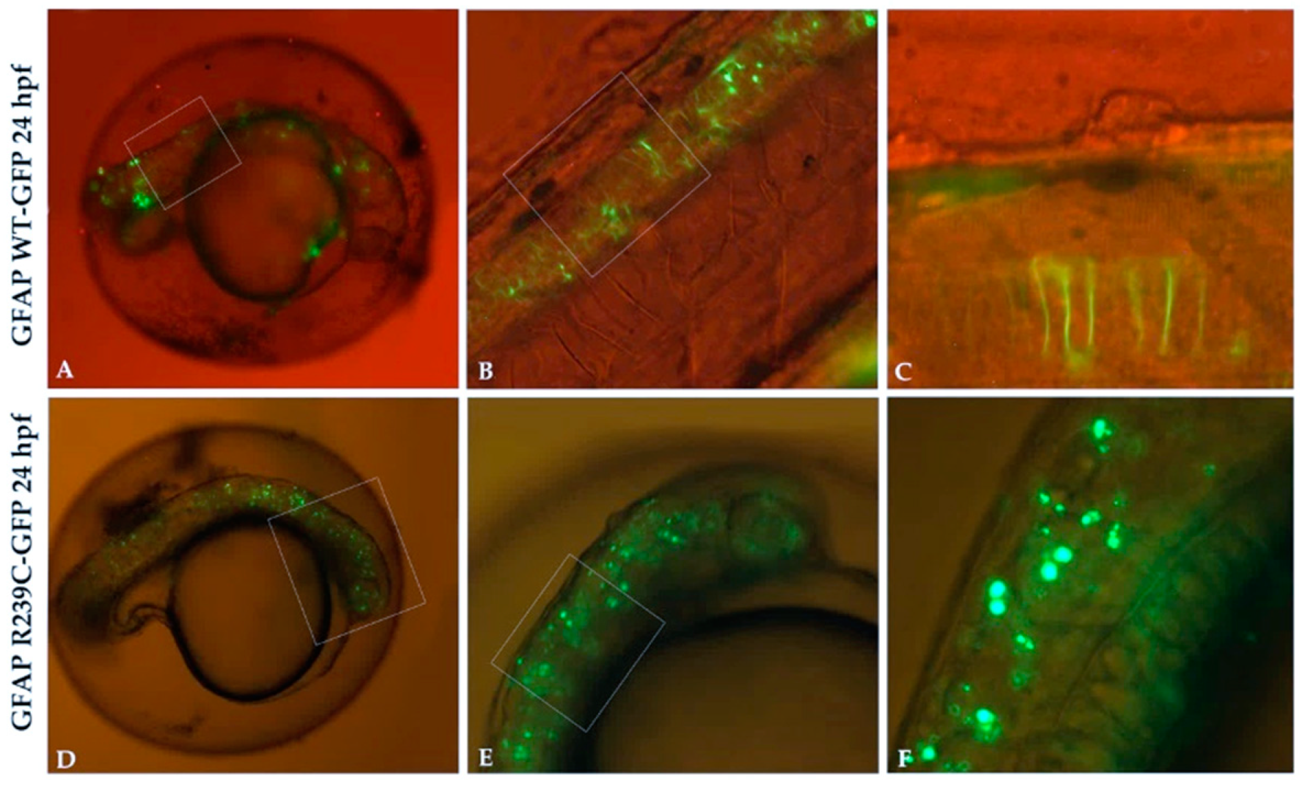
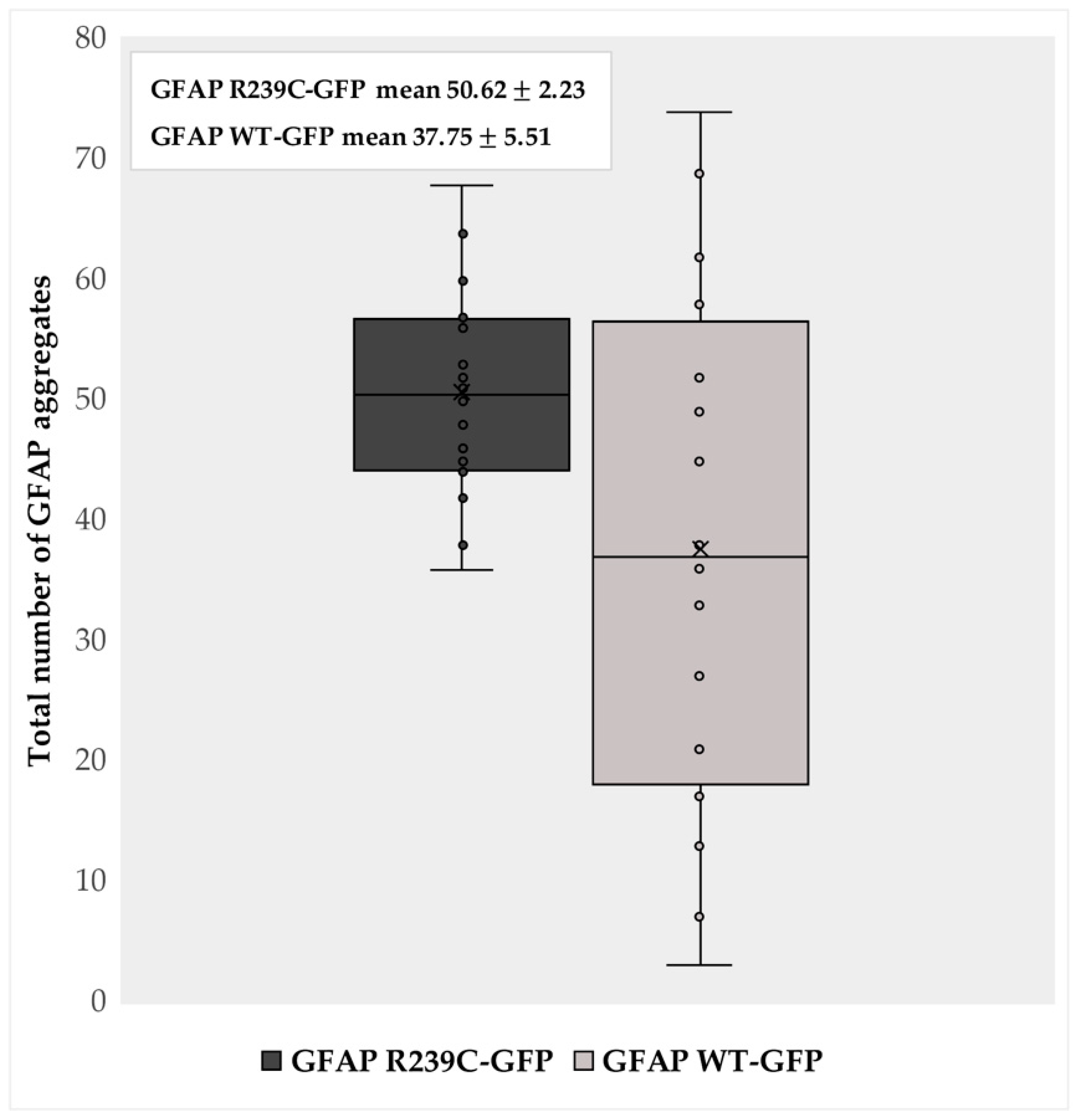
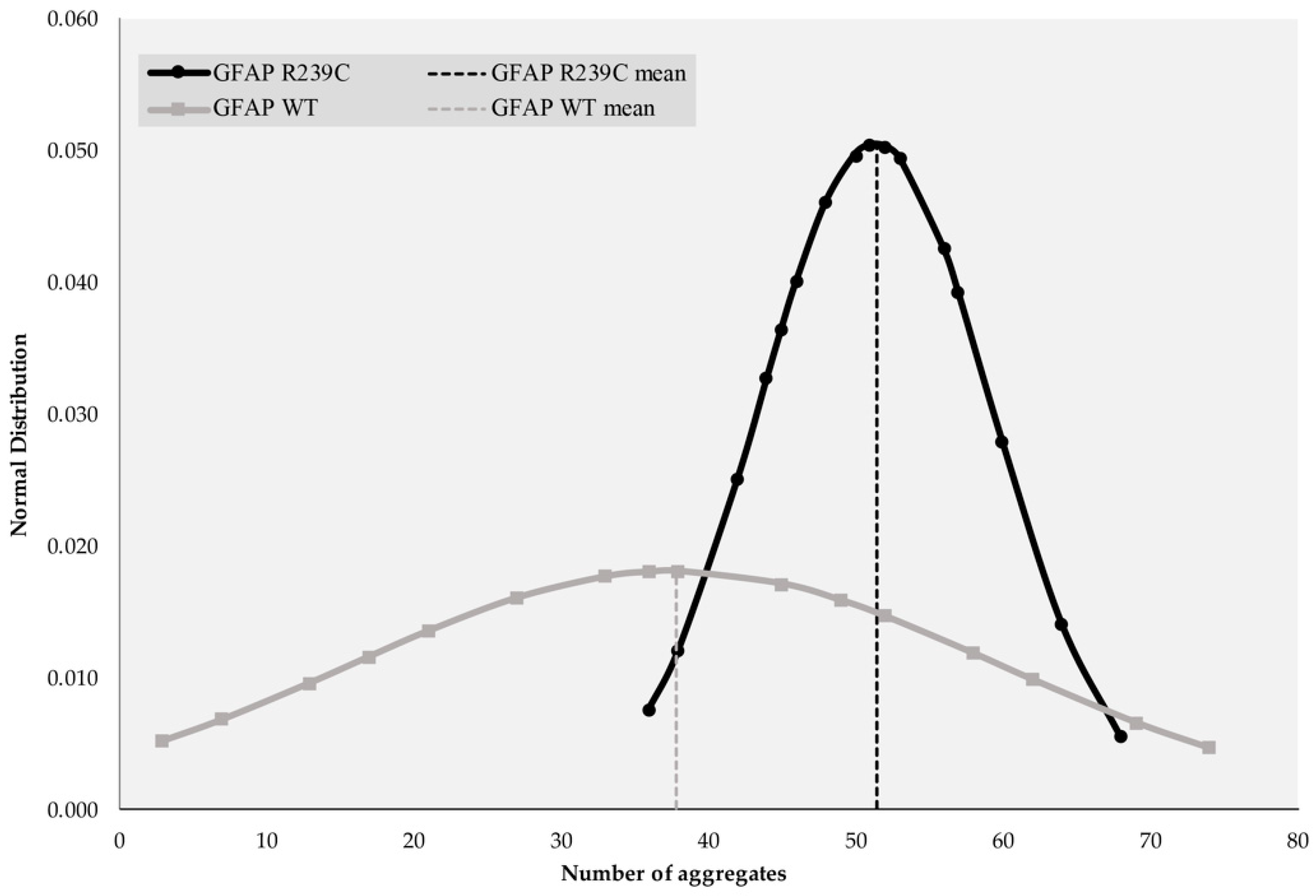
3.1. Localization and Quantification of GFAP Aggregates
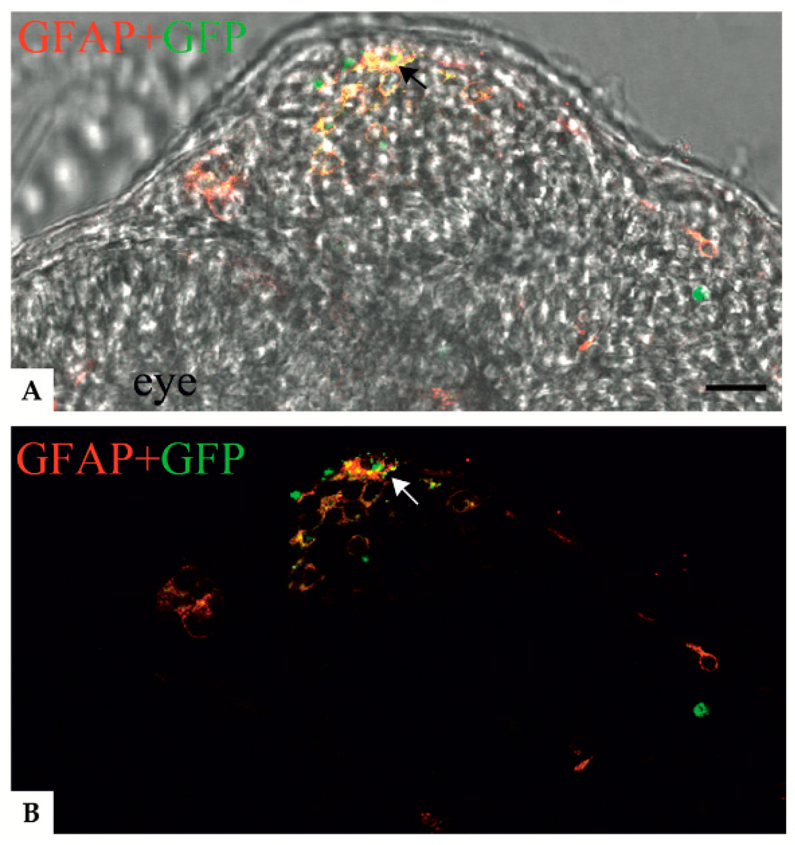
3.2. Localization of Mutant GFAP Aggregates
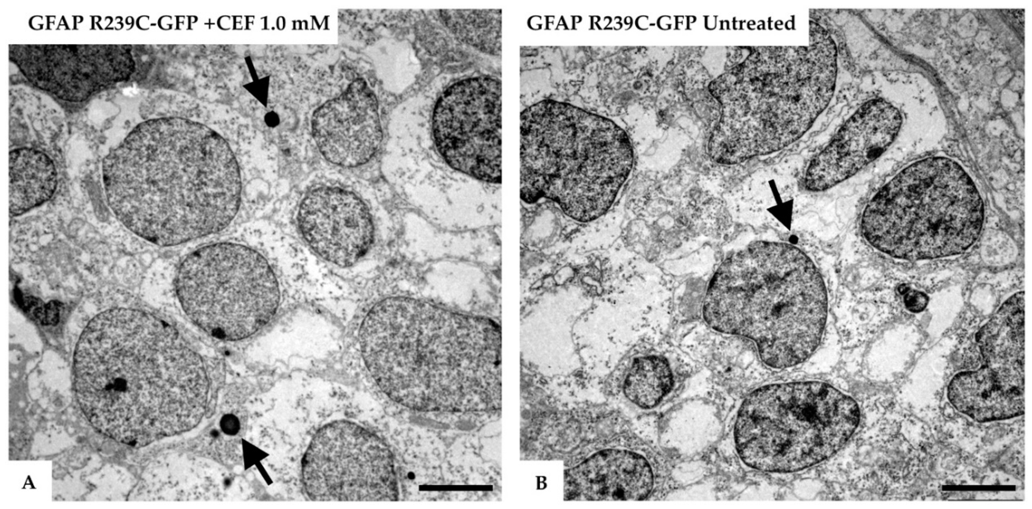
3.3. Effects of Ceftriaxone Treatments
3.4. Stimulation Effects of the Small Heat-Shock Proteins
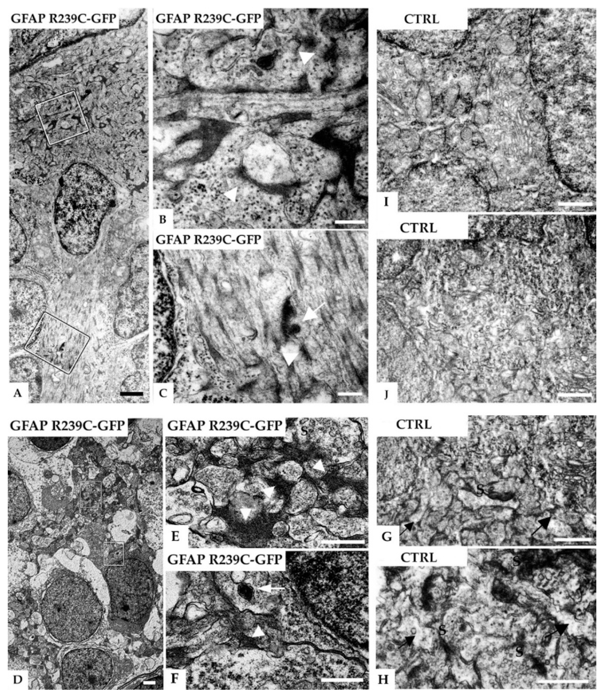
3.5. Ultrastructural Analysis of the Zebrafish Model of AxD
4. Discussion
5. Conclusions
Supplementary Materials
Author Contributions
Funding
Acknowledgments
Conflicts of Interest
References
- Prust, M.; Wang, J.; Morizono, H.; Messing, A.; Brenner, M.; Gordon, E.; Hartka, T.; Sokohl, A.; Schiffmann, R.; Gordish-Dressman, H.; et al. GFAP mutations, age at onset, and clinical subtypes in Alexander disease. Neurology 2011, 77, 1287–1294. [Google Scholar] [CrossRef] [PubMed]
- Messing, A.; LaPash Daniels, C.M.; Hagemann, T.L. Strategies for treatment in Alexander disease. Neurotherapeutics 2010, 7, 507–515. [Google Scholar] [CrossRef] [PubMed]
- Brenner, M.; Johnson, A.B.; Boespflug-Tanguy, O.; Rodriguez, D.; Goldman, J.E.; Messing, A. Mutations in GFAP, encoding glial fibrillary acidic protein, are associated with Alexander disease. Nat. Genet. 2001, 27, 117–120. [Google Scholar] [CrossRef] [PubMed]
- Nielsen, A.L.; Jørgensen, A.L. Structural and functional characterization of the zebrafish gene for glial fibrillary acidic protein, GFAP. Gene 2003, 310, 123–132. [Google Scholar] [CrossRef]
- Pekny, M.; Pekna, M. Astrocyte reactivity and reactive astrogliosis: Costs and benefits. Physiol. Rev. 2014, 94, 1077–1098. [Google Scholar] [CrossRef]
- Messing, A.; Brenner, M.; Feany, M.B.; Nedergaard, M.; Goldman, J.E. Alexander disease. J. Neurosci. 2012, 32, 5017–5023. [Google Scholar] [CrossRef]
- Lee, S.-H.; Nam, T.-S.; Kim, K.-H.; Kim, J.H.; Yoon, W.; Heo, S.-H.; Kim, M.J.; Shin, B.A.; Perng, M.-D.; Choy, H.E.; et al. Aggregation-prone GFAP mutation in Alexander disease validated using a zebrafish model. BMC Neurol. 2017, 17, 175. [Google Scholar] [CrossRef]
- Der Perng, M.; Su, M.; Wen, S.F.; Li, R.; Gibbon, T.; Prescott, A.R.; Brenner, M.; Quinlan, R.A. The Alexander disease-causing glial fibrillary acidic protein mutant, R416W, accumulates into Rosenthal fibers by a pathway that involves filament aggregation and the association of α B-crystallin and HSP27. Am. J. Hum. Genet. 2006, 79, 197–213. [Google Scholar] [CrossRef]
- Hagemann, T.L.; Boelens, W.C.; Wawrousek, E.F.; Messing, A. Suppression of GFAP toxicity by alphaB-crystallin in mouse models of Alexander disease. Hum. Mol. Genet. 2009, 18, 1190–1199. [Google Scholar] [CrossRef]
- Bachetti, T.; Di Zanni, E.; Balbi, P.; Bocca, P.; Prigione, I.; Deiana, G.A.; Rezzani, A.; Ceccherini, I.; Sechi, G. In vitro treatments with ceftriaxone promote elimination of mutant glial fibrillary acidic protein and transcription down-regulation. Exp. Cell Res. 2010, 316, 2152–2165. [Google Scholar] [CrossRef]
- Bachetti, T.; Di Zanni, E.; Balbi, P.; Ravazzolo, R.; Sechi, G.; Ceccherini, I. Beneficial effects of curcumin on GFAP filament organization and down-regulation of GFAP expression in an in vitro model of Alexander disease. Exp. Cell Res. 2012, 318, 1844–1854. [Google Scholar] [CrossRef] [PubMed]
- Dooley, K.; Zon, L.I. Zebrafish: A model system for the study of human disease. Curr. Opin. Genet. Dev. 2000, 10, 252–256. [Google Scholar] [CrossRef]
- Howe, K.; Clark, M.D.; Torroja, C.F.; Torrance, J.; Berthelot, C.; Muffato, M.; Collins, J.E.; Humphray, S.; McLaren, K.; Matthews, L.; et al. The zebrafish reference genome sequence and its relationship to the human genome. Nature 2013, 496, 498–503. [Google Scholar] [CrossRef] [PubMed]
- Saleem, S.; Kannan, R.R. Zebrafish: An emerging real-time model system to study Alzheimer’s disease and neurospecific drug discovery. Cell Death Discov. 2018, 4, 45. [Google Scholar] [CrossRef]
- Blader, P.; Strähle, U. Zebrafish developmental genetics and central nervous system development. Hum Mol. Genet. 2000, 9, 945–951. [Google Scholar] [CrossRef]
- Schmidt, R.; Strähle, U.; Scholpp, S. Neurogenesis in zebrafish-from embryo to adult. Neural Dev. 2013, 8, 3. [Google Scholar] [CrossRef]
- Grupp, L.; Wolburg, H.; Mack, A.F. Astroglial structures in the zebrafish brain. J. Comp. Neurol. 2010, 518, 4277–4287. [Google Scholar] [CrossRef]
- Lyons, D.A.; Talbot, W.S. Glial cell development and function in zebrafish. Cold Spring Harb. Perspect. Biol. 2014, 7, a020586. [Google Scholar] [CrossRef]
- Schnorrer, F.; Luschnig, S.; Koch, I.; Nüsslein-Volhard, C. γ-tubulin37C and γ-tubulin ring complex protein 75 are essential for bicoid RNA localization during drosophila oogenesis. Dev. Cell 2002, 3, 685–696. [Google Scholar] [CrossRef]
- Bachetti, T.; Caroli, F.; Bocca, P.; Prigione, I.; Balbi, P.; Biancheri, R.; Filocamo, M.; Mariotti, C.; Pareyson, D.; Ravazzolo, R.; et al. Mild functional effects of a novel GFAP mutant allele identified in a familial case of adult-onset Alexander disease. Eur. J. Hum. Genet. 2008, 16, 462–470. [Google Scholar] [CrossRef]
- Kawakami, K. Tol2: A versatile gene transfer vector in vertebrates. Genome Biol. 2007, 8 (Suppl. 1), S7. [Google Scholar] [CrossRef] [PubMed]
- Walker, S.E.; Lorsch, J. RNA purification--precipitation methods. Methods Enzymol. 2013, 530, 337–343. [Google Scholar] [CrossRef] [PubMed]
- Schneider, C.A.; Rasband, W.S.; Eliceiri, K.W. NIH Image to ImageJ: 25 years of image analysis. Nat. Methods 2012, 9, 671–675. [Google Scholar] [CrossRef] [PubMed]
- Mao, L.; Shelden, E.A. Developmentally regulated gene expression of the small heat shock protein Hsp27 in zebrafish embryos. Gene Expr. Patterns 2006, 6, 127–133. [Google Scholar] [CrossRef] [PubMed]
- Suster, M.L.; Kikuta, H.; Urasaki, A.; Asakawa, K.; Kawakami, K. Transgenesis in zebrafish with the tol2 transposon system. Methods Mol. Biol. 2009, 561, 41–63. [Google Scholar] [CrossRef] [PubMed]
- Tanaka, K.F.; Takebayashi, H.; Yamazaki, Y.; Ono, K.; Naruse, M.; Iwasato, T.; Itohara, S.; Kato, H.; Ikenaka, K. Murine model of Alexander disease: Analysis of GFAP aggregate formation and its pathological significance. Glia 2007, 55, 617–631. [Google Scholar] [CrossRef] [PubMed]
- Hsiao, V.C.; Tian, R.; Long, H.; Der Perng, M.; Brenner, M.; Quinlan, R.A.; Goldman, J.E. Alexander-disease mutation of GFAP causes filament disorganization and decreased solubility of GFAP. J. Cell Sci. 2005, 118, 2057–2065. [Google Scholar] [CrossRef]
- Sechi, G.; Ceccherini, I.; Bachetti, T.; Deiana, G.A.; Sechi, E.; Balbi, P. Ceftriaxone for Alexander’s Disease: A Four-Year Follow-Up. JIMD Rep. 2013, 9, 67–71. [Google Scholar] [CrossRef]
- Jany, P.L.; Hagemann, T.L.; Messing, A. GFAP expression as an indicator of disease severity in mouse models of Alexander disease. ASN Neuro 2013, 5, e00109. [Google Scholar] [CrossRef]
- Bernardos, R.L.; Raymond, P.A. GFAP transgenic zebrafish. Gene Expr. Patterns 2006, 6, 1007–1013. [Google Scholar] [CrossRef]
- Marvin, M.; O’Rourke, D.; Kurihara, T.; Juliano, C.E.; Harrison, K.L.; Hutson, L.D. Developmental expression patterns of the zebrafish small heat shock proteins. Dev. Dyn. 2008, 237, 454–463. [Google Scholar] [CrossRef] [PubMed]
- Wang, L.; Colodner, K.J.; Feany, M.B. Protein misfolding and oxidative stress promote glial-mediated neurodegeneration in an Alexander disease model. J. Neurosci. 2011, 31, 2868–2877. [Google Scholar] [CrossRef] [PubMed]
- Tang, G.; Yue, Z.; Tallóczy, Z.; Goldman, J.E. Adaptive autophagy in Alexander disease-affected astrocytes. Autophagy 2008, 4, 701–703. [Google Scholar] [CrossRef] [PubMed]

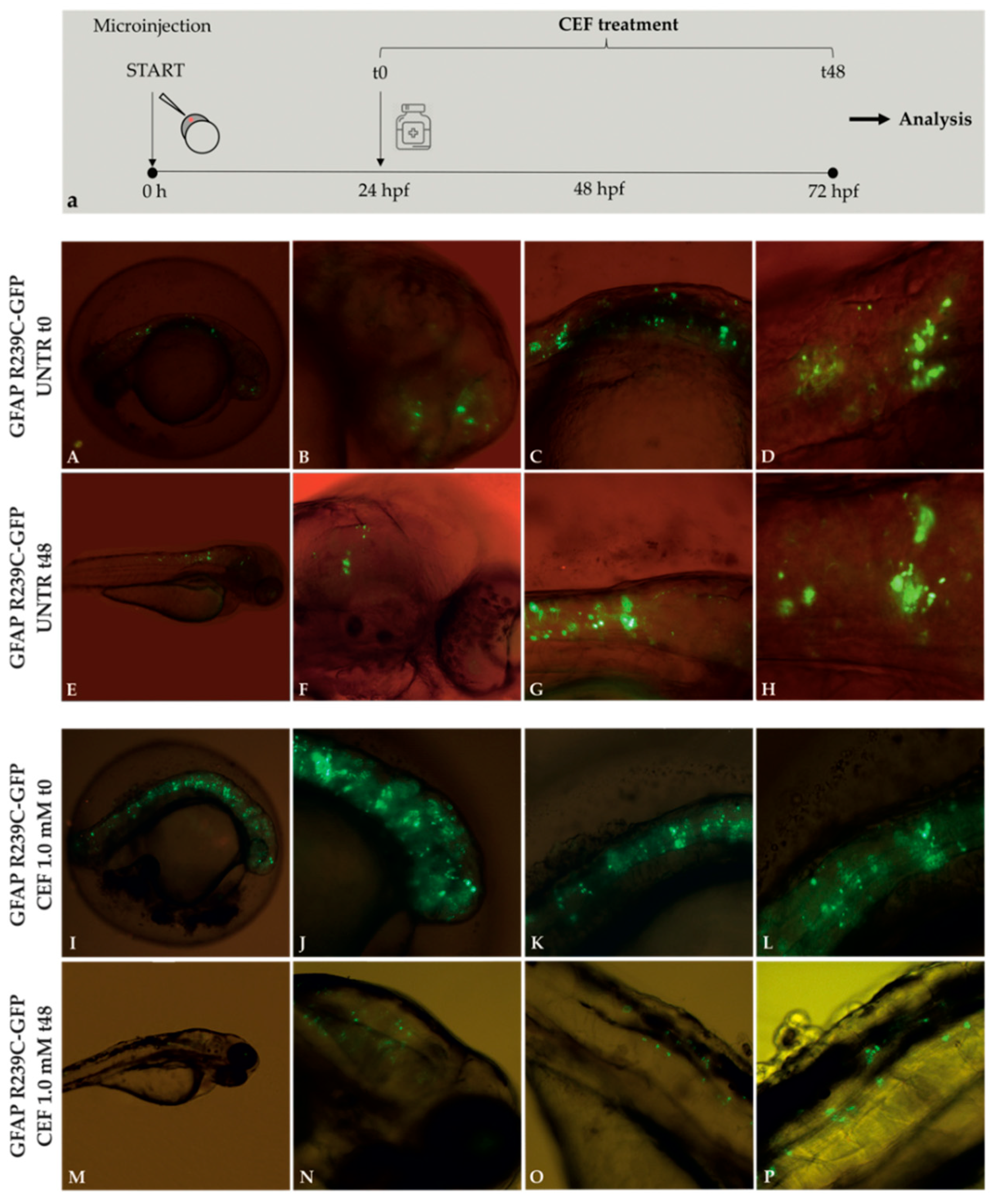
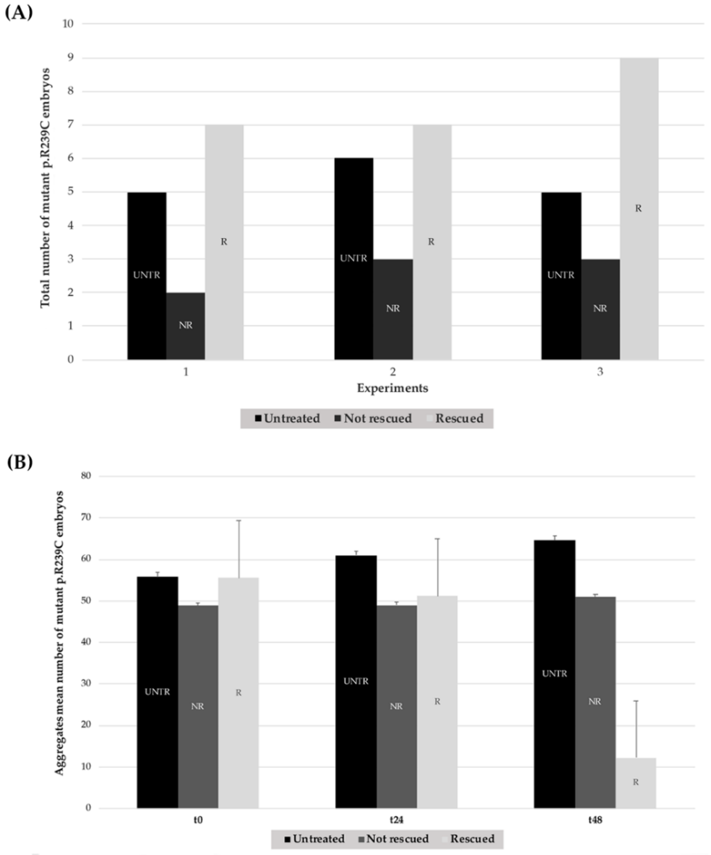

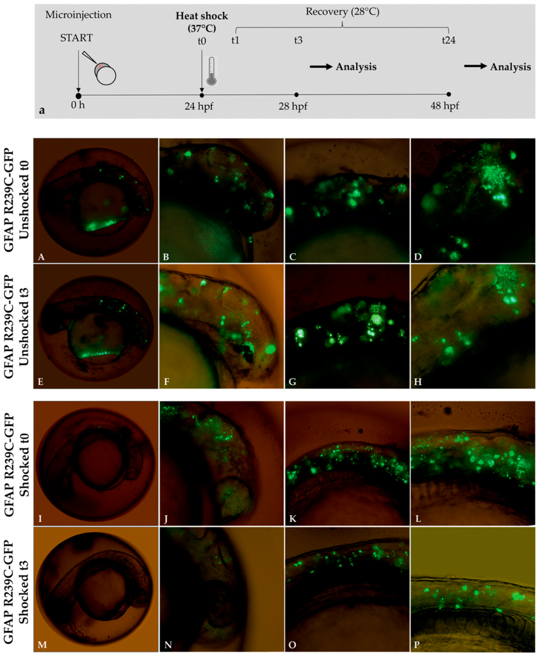
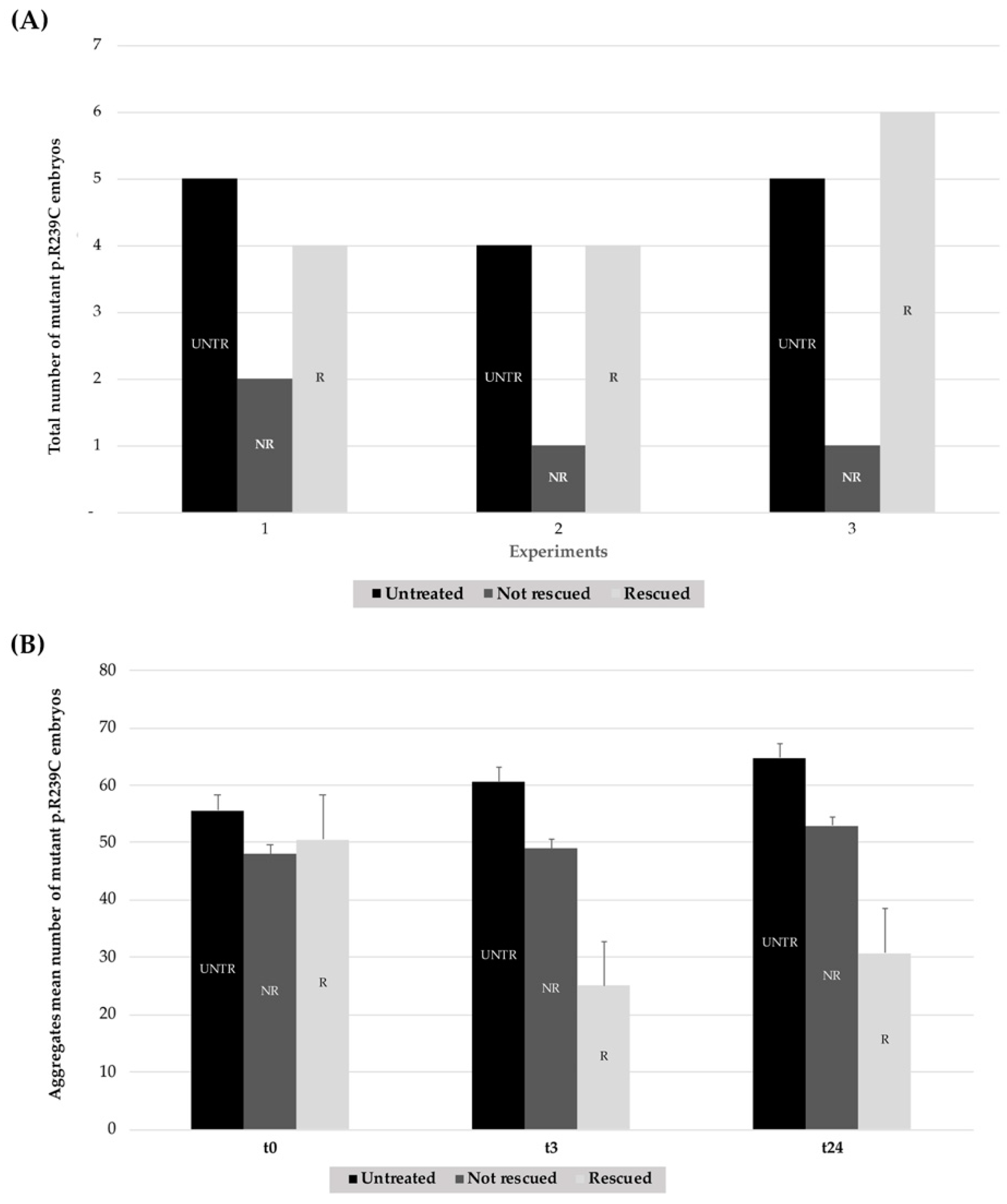
| Number of Mutant p.R239C Embryos Treated with CEF 1.0 mM | ||||
|---|---|---|---|---|
| Experiment | Untreated | Treated | Rescued | % Rescued |
| n°1 | 5 | 9 | 7 | 77.70% |
| n°2 | 6 | 10 | 7 | 70.00% |
| n°3 | 5 | 12 | 9 | 75.00% |
| Total | 16 | 31 | 23 | 74.20% ± 3.91% |
| Aggregates Mean Number of Untreated Mutant p.R239C Embryos | |||
|---|---|---|---|
| Experiment | t0 | t24 | t48 |
| n°1 | 55.60 | 59.60 | 64.00 |
| n°2 | 58.00 | 63.67 | 67.67 |
| n°3 | 53.60 | 59.40 | 61.60 |
| Mean ± SD | 55.88 ± 11.43 | 61.06 ± 15.36 | 64.63 ± 19.94 |
| Aggregates Mean Number of Treated Mutant p.R239C Embryos | |||
|---|---|---|---|
| Experiment | t0 | t24 | t48 |
| n°1 | 55.44 | 51.33 | 19.33 |
| n°2 | 58.45 | 52.09 | 25.91 |
| n°3 | 52.80 | 48.40 | 21.80 |
| Mean ± SD | 55.57 ± 11.17 | 50.61 ± 10.73 | 22.35 ± 19.27 |
| Number of Shocked Mutant p.R239C Embryos | ||||
|---|---|---|---|---|
| Experiment | Untreated | Shocked | Rescued | % Rescued |
| n°1 | 5 | 6 | 4 | 66.6% |
| n°2 | 4 | 5 | 4 | 80.0% |
| n°3 | 5 | 7 | 6 | 85.7% |
| Total | 14 | 18 | 14 | 77.40% ± 9.81% |
| Aggregates Mean Number of Unshocked Mutant p.R239C Embryos | |||
|---|---|---|---|
| Experiment | t0 | t3 | t24 |
| n°1 | 53.20 | 54.80 | 58.80 |
| n°2 | 57.00 | 63.25 | 67.00 |
| n°3 | 56.80 | 64.20 | 68.80 |
| Mean ± SD | 55.57 ± 8.36 | 60.57 ± 11.24 | 64.71 ± 15.19 |
| Aggregates Mean Number of Shocked Mutant p.R239C Embryos | |||
|---|---|---|---|
| Experiment | t0 | t3 | t24 |
| n°1 | 47.67 | 35.50 | 39.67 |
| n°2 | 50.80 | 30.00 | 35.20 |
| n°3 | 51.43 | 26.43 | 32.71 |
| Mean ± SD | 49.97 ± 9.95 | 30.64 ± 11.65 | 35.86 ± 11.27 |
Publisher’s Note: MDPI stays neutral with regard to jurisdictional claims in published maps and institutional affiliations. |
© 2020 by the authors. Licensee MDPI, Basel, Switzerland. This article is an open access article distributed under the terms and conditions of the Creative Commons Attribution (CC BY) license (http://creativecommons.org/licenses/by/4.0/).
Share and Cite
Candiani, S.; Carestiato, S.; Mack, A.F.; Bani, D.; Bozzo, M.; Obino, V.; Ori, M.; Rosamilia, F.; De Sarlo, M.; Pestarino, M.; et al. Alexander Disease Modeling in Zebrafish: An In Vivo System Suitable to Perform Drug Screening. Genes 2020, 11, 1490. https://doi.org/10.3390/genes11121490
Candiani S, Carestiato S, Mack AF, Bani D, Bozzo M, Obino V, Ori M, Rosamilia F, De Sarlo M, Pestarino M, et al. Alexander Disease Modeling in Zebrafish: An In Vivo System Suitable to Perform Drug Screening. Genes. 2020; 11(12):1490. https://doi.org/10.3390/genes11121490
Chicago/Turabian StyleCandiani, Simona, Silvia Carestiato, Andreas F. Mack, Daniele Bani, Matteo Bozzo, Valentina Obino, Michela Ori, Francesca Rosamilia, Miriam De Sarlo, Mario Pestarino, and et al. 2020. "Alexander Disease Modeling in Zebrafish: An In Vivo System Suitable to Perform Drug Screening" Genes 11, no. 12: 1490. https://doi.org/10.3390/genes11121490
APA StyleCandiani, S., Carestiato, S., Mack, A. F., Bani, D., Bozzo, M., Obino, V., Ori, M., Rosamilia, F., De Sarlo, M., Pestarino, M., Ceccherini, I., & Bachetti, T. (2020). Alexander Disease Modeling in Zebrafish: An In Vivo System Suitable to Perform Drug Screening. Genes, 11(12), 1490. https://doi.org/10.3390/genes11121490


