Abstract
Improving sowing quality is crucial for ensuring wheat emergence and healthy growth. To address issues of poor wheat sowing quality, such as uneven sowing depth and inadequate soil coverage, in the Yangtze River Delta region of China, this study systematically analyzed the effects of the implement’s structural and operational parameters on sowing quality. Based on this analysis, a double-shaft rotary tillage and double-press seeder was designed. Protrusions on the grooving press roller are used to form seed furrows, rotary tiller blades cover the seeds with soil, and the rear press roller compacts the soil. DEM-MBD (discrete element method–multibody dynamics) coupled simulations, combined with single-factor and central composite design (CCD) experiments, were conducted with seeding depth as the evaluation index and four experimental factors: the protrusion height on the press grooving roller, forward speed, seed mass in the seed box, and straw mulching amount. The optimal protrusion height was 29 mm. The effects of rotary tiller blade working depth, rotational speed, and forward speed on soil-covering mass and its coefficient of variation were evaluated through discrete element method (DEM) simulations. The optimal working depth and rotational speed were found to be 55 mm and 350 r·min−1, respectively, based on single-factor and Box–Behnken Design experiments. Field experiments based on optimized parameters showed results consistent with the simulations. The qualified rate of seeding depth decreased as forward speed increased. The optimal forward speed was 4.5 km·h−1, at which the average seeding depth was 25.7 mm, the qualified seeding depth rate was 90%, the soil-covering mass within a 50 cm2 area was 143.2 g, and the coefficient of variation was 13.21%, meeting the requirements for wheat sowing operations.
1. Introduction
Wheat is one of the world’s major staple crops, and the quality of sowing operations directly affects its growth and yield [1,2,3]. In the Yangtze River Delta region of China, factors such as heavy clay soils and high straw residue often lead to issues during traditional sowing operations, including uneven seeding depth, poor soil covering, and inadequate pressing. These problems negatively impact wheat emergence rates and the uniformity of crop growth [4,5,6]. The formation of seed furrows, soil covering, and pressing are key processes in wheat sowing. Proper control of seeding depth and improvement of soil covering quality are of great significance for enhancing wheat yield [7,8].
In recent years, considerable research has been conducted on wheat sowing implements, which mainly fall into two categories. The first focuses on optimizing individual sowing components. Parihar et al. developed a serrated concave disc seeder that uses serrated discs to cut and clear field straw, allowing seeds to be evenly deposited into the soil [9]. Compared with traditional double-disc seeders, this new design enables direct sowing in paddy stubble fields, thereby avoiding air pollution and loss of soil organic matter caused by straw burning, reducing energy consumption, and improving wheat yield. Yatskul et al. optimized the structural parameters of the air distributor in pneumatic seeders, determining the minimum airflow velocity and flow concentration for pipes of different diameters corresponding to various seed types, and established a method for measuring the velocity of loaded airflow, providing an energy-efficient approach to optimizing seeders [10]. Yin et al. addressed the challenge of cutting maize straw during sowing by designing a vibrating anti-blockage cutting device, with its structural parameters determined through theoretical analysis and experiments [11]. Malasli et al. designed a disc-type furrow opener and optimized parameters such as disc angle, tilt angle, and vertical load to improve operational quality [12]. Lu et al. developed a star-toothed spherical disc soil covering device and employed DEM simulations to determine the optimal installation angle, spacing, and working depth of the disc, which can replace unreliable V-shaped pressing soil covering devices under clay soil conditions [13].
The second research category involves the overall design and optimization of multifunctional sowing machines. Yaseen et al. developed a novel precision crop seeder that uses C-shaped blades for straw chopping, V-shaped furrow openers for seed furrow formation, and innovative seed and fertilizer metering devices for precise placement, enabling one-pass operations including stubble removal, mixing, seed furrow formation, sowing, and fertilization [14]. Li et al. designed a wet-tolerant rotary strip no-till seeder that utilizes C-shaped rotary tiller blades for seed furrow formation and replaces the conventional press wheel with a ground wheel wrapped in rubber for seed pressing [15]. In addition, stainless steel chains are employed to optimize seed covering. Compared with conventional seeders, this implement significantly improves wheat emergence rates. Bai et al. developed a single-shaft rotary precision seeder for shallow-buried wide-bed drip irrigation in wheat, capable of simultaneously leveling nine rows of wheat seedbeds, laying drip irrigation tapes, precision sowing, variable-rate fertilization, and soil covering [16]. He et al. addressed the problem of poor sowing quality caused by loose seedbed soil in the Huang-Huai-Hai region by designing a double-compaction seeder, which improves the seedbed environment and seeding depth uniformity through pre-sowing and seed furrow pressing [17]. Zhang et al. developed a new seeder equipped with a single-side guide wheel and conducted comparative tests with two traditional seeders (dual-side guide wheels and rear guide wheel depth control mechanisms) using sowing spacing, seeding depth, and emergence time as evaluation indices. Results showed that the new single-side guide wheel seeder exhibited superior performance [18].
The aforementioned studies have mainly focused on optimizing individual sowing components or designing multifunctional sowing implements, aiming to enhance seeder performance and thus increase crop yield. However, although several studies have optimized structural and operational parameters, comprehensive research on the synergistic effects and interactions among multiple parameters on sowing quality remains limited. Our team previously proposed a tube-free wheat sowing method that demonstrated higher sowing precision and emergence rates compared to conventional tube-type sowing, but studies on parameter optimization for soil covering during double-press sowing and the factors influencing seeding depth have not yet been conducted [19,20]. Therefore, this study designs a double-shaft rotary tillage and double-press seeder, optimizes soil covering parameters for double-pressing sowing, investigates the effects of implement structural and operational parameters on wheat sowing quality, determines optimal operational parameters through a combination of theoretical analysis and simulation experiments, and finally validates the results through field experiments.
2. Materials and Methods
2.1. Overall Structural Principle of the Double-Shaft Rotary Tillage and Double-Press Seeder
The double-shaft rotary tillage and double-press seeder were designed and developed in this study based on the principle of combined operations, aiming to improve sowing efficiency. It consists of a rotary tiller and a seeder, which are connected by parallelogram linkage. The overall structure of the seeder is illustrated in Figure 1. A 210-horsepower tractor is employed as the power source, and the implement featured a working width of 2.5 m. Due to the complex field conditions, the implement experiences vibrations during operation. The rotary tiller is equipped with L-type blades: the front rotor utilizes blades with a rotational radius of 245 mm, while the rear rotor is fitted with blades of 225 mm radius. The front rotor is assembled with 32 pairs of blades and the rear rotor with 29 pairs. Both rotors adopt a double-helical blade arrangement, with two blades mounted on the same rotational plane at a phase angle of 155° and a phase angle of 75° between two adjacent blades along the same helix. Power is transmitted from the tractor to the rotary tiller via a two-stage gearbox. Both the front and rear rotors operated at a rotational speed of 250 r·min−1.
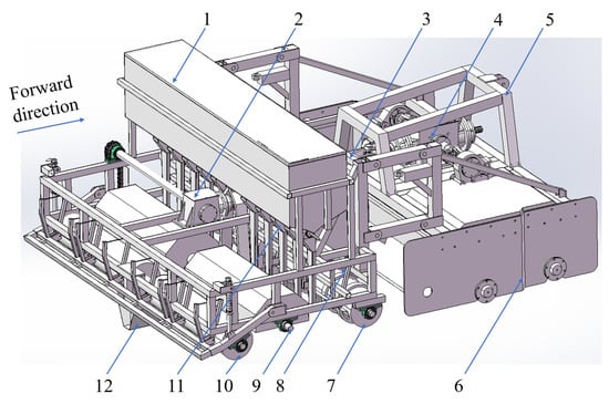
Figure 1.
Double-shaft rotary tillage and double-press seeder: 1. seed box; 2. seeder gearbox; 3. intermediate power transmission shaft; 4. rotary tiller gearbox; 5. frame; 6. double-shaft rotary tillage unit; 7. press grooving roller; 8. furrow opener; 9. soil covering device; 10. rear press roller; 11. seed metering device; 12. furrow shaper.
The structure of the double-press rotary tilling soil covering device within the seeder is illustrated in Figure 2. This device mainly consists of a press grooving roller with protrusions, a rotary tiller blade assembly, and a rear press roller. The press grooving roller and rotary tiller blade assembly are driven by the tractor’s power via a gearbox, whereas the rear press roller is ground-driven. During operation, the rotary tiller performs double-shaft cutting and rotary tillage on untilled land. After tillage, the furrow opener forms the initial shape of the drainage (a furrow to facilitate water drainage during rainfall), and the furrow shaper presses the soil downward to consolidate the furrow. As the implement advances, the press grooving roller goes over the tilled soil, compacting the surface soil. The specially designed protrusions on the press grooving roller not only compact the soil but also form seed furrows. Seeds are delivered into the seed furrows by seed metering devices driven by an electric motor and then covered by the rotary tiller blades. Finally, the rear press roller performs a second compaction, completing the sowing operation.
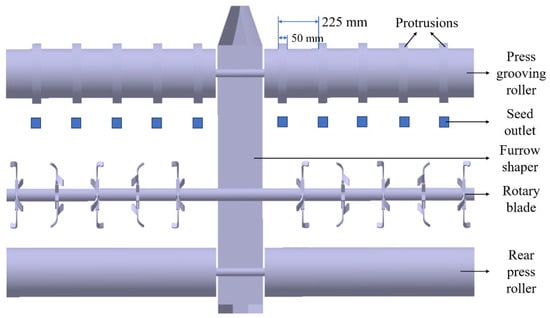
Figure 2.
Top view of the double-press rotary tilling soil covering device.
2.2. Main Factors Affecting Seeding Depth
Wide-strip planting agronomy enhances wheat yield [21,22]. The seeder adopts a wide-strip planting technique with a strip width of 50 mm, row spacing of 225 mm, and target seeding depth of 25 mm. According to the Chinese Agricultural Industry Standard NY/T 1143-2006 “Technical Specification for Quality Evaluation of Seeders”, a seeding depth of 25 ± 5 mm is considered qualified [23]. Seeding operations primarily comprise four processes: seed furrow opening, seed placement, soil covering, and pressing. Protrusions on the press grooving roller form seed furrows, where protrusion height determines furrow depth. Greater furrow depth results in increased seeding depth. An increase in forward speed reduces the duration of roller-soil contact, which in turn decreases the extent of soil surface compression [24]. As a result, the soil surface is not pressed down as much, and the vertical distance between the seed and the soil surface becomes greater, thereby increasing the seeding depth. Pre-seeding, double-shaft rotary tillers achieve homogeneous straw-soil mixing via tillage. The rotating blades of the two shafts cut and stir the straw and soil thoroughly, resulting in a uniform mixture. Straw within the soil layer alters soil structure, influencing compaction efficiency during front/rear roller operation and subsequently affecting seeding depth [25]. The front press grooving roller is rigidly connected to the frame, while the rear press roller is attached via pins and springs, forming a resilient connection that allows it to float vertically. The seeder weighs approximately 824 kg, and the maximum seed capacity of the seed box is 500 kg. As seed mass decreases during operation, the press grooving roller’s soil compaction force diminishes. Reduced compaction force decreases post-compaction soil firmness, leading to greater soil compression by the rear press roller and consequently decreased seeding depth. During compaction by the rear press roller after soil covering, seeds within the furrows are subjected to downward displacement due to the applied pressure, which further affects the seeding depth.
During operation, soil reaction forces concentrate primarily on the furrow shaper, with the press grooving roller bearing only a minor portion of the total support force. To measure press grooving roller compaction force, pressure sensors were installed between the roller bearing housing and frame. The force measured at this interface generally represents the soil compaction force exerted by the press grooving roller, although variations may occur depending on soil moisture content and soil type (such as clay, sandy, or silty soils). Experiments with varying seed masses in the seed box established the relationship between press grooving roller compaction force and seed mass, as illustrated in Figure 3.
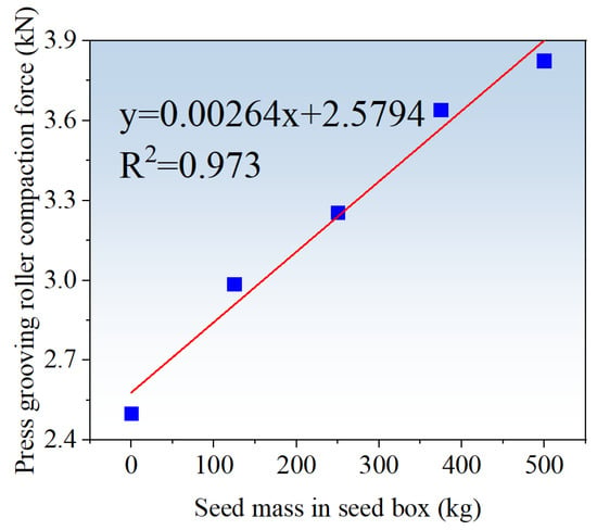
Figure 3.
Variation curve of press grooving roller compaction force (simple linear regression, n = 5).
Figure 4 illustrates the force analysis diagram of the rear press roller. The spring primarily serves as a cushion during vertical floating of the roller. Its low elastic coefficient renders the elastic force negligible. Minimal soil compression occurs before and after compaction. Thus, the effect of compression on the direction of support force F2 is neglected, with the force assumed to be vertically upward. Force equilibrium analysis of the roller yields:
where F1 is the frame’s axial tensile force on the roller (N). F2 is the soil support force on the roller (N). f is rolling friction between the roller and the ground (N); as a driven wheel, f opposes the working direction. β is the angle between the roller bearing housing and the horizontal plane (°). G is the gravitational force on the roller (N).
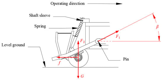
Figure 4.
Force analysis of rear press roller.
The value of the compaction force exerted by the roller on the soil surface is equal to F2. From Equation (1), F2 is expressed as follows:
Field experiments indicate that β ranges from 28° to 32°. The total mass of the press component is 139.7 kg, gravitational acceleration is 9.81 m·s−2, and the rolling friction coefficient between soil and the rear press roller is 0.125 [13]. F2 is calculated to be between 1263 N and 1279 N. The mean value (1271 N) is taken as the rear press roller compaction force.
Per wheat agronomic requirements, soil should completely fill seed furrows with a slight convexity after covering. The rotary tiller blades, which feature a 195 mm rotation radius, must operate at an optimal depth. Insufficient working depth causes inadequate covering, while excessive depth can disturb or damage seed furrows, thereby compromising seeding quality. Thus, optimal rotary tiller blade working depth is essential. Beyond rotary tiller blade working depth, rotational speed and forward speed also affect covering quality. Higher rotational speeds increase centrifugal force exerted on soil particles, enhancing kinetic energy and throwing distance, thereby influencing coverage area. Conversely, at higher forward speeds, the distance between two consecutive soil-cutting points (i.e., the soil-cutting interval) increases and the interaction time between the blades and the soil decreases, both of which result in the formation of larger soil clods and negatively impact the quality of soil covering.
In summary, seeding depth is influenced by several factors, including straw mulching amount, protrusion height on the press grooving roller, seed mass in the seed box, rotary tiller blade working depth, rotational speed, and forward speed. The operation sequence of the implement consists of seed furrow opening, seeding, and soil covering. The depth of the seed furrow determines the mass of soil used for covering. Considering the complexity of these factors, this study first employs the DEM-MBD coupled simulation to investigate the effects of dual-roller compaction on seeding depth. After determining the optimal protrusion height on the press grooving roller, a soil bin model with seed furrows was developed. Subsequently, DEM simulations are conducted to optimize the operational parameters of the rotary tiller blades.
2.3. DEM-MBD Coupled Simulation Experiments of Double Pressing
2.3.1. DEM-MBD Coupled Simulation Model of Double Pressing
Soil samples were collected from a rice stubble experimental field in Jiangdu District, Yangzhou City, China, with rice roots present in the soil layer. The soil type is fluvisol, formed by sedimentation from the Yangtze River and Huai River. Three soil samples were collected from the topsoil layer (0–225 mm) and the subsoil layer (225–450 mm), each retaining intact rice root systems. The measured mean particle density of the three soil samples represents the combined density of the soil and the rice root system. The topsoil was modelled using aggregates with a radius of 5 mm, while the subsoil was modelled using aggregates with a radius of 10 mm. The Edinburgh Elasto-Plastic Adhesion contact model was employed [26]. Based on soil uniaxial compression experiments, the discrete element model parameters were calibrated by first using the Plackett–Burman design to identify key parameters affecting soil compression and then applying the Box–Behnken Design (BBD) to optimize these parameters to match experimental results. The calibration process is summarized in Table 1. The restitution coefficient between the topsoil and the subsoil was 0.3, the static friction coefficient was 0.5, and the rolling friction coefficient was 0.3.

Table 1.
Soil discrete element model parameters.
Three random sampling locations were selected in the experiment field, with ten broken straws collected from each location. Figure 5a illustrates the schematic diagram for measuring straw length using a steel ruler. Diameter was measured using a vernier caliper. The average values were calculated, resulting in an average length of 85.4 mm and an average diameter of 4.96 mm. The measured straw density was 0.153 Mg·m−3. The Poisson’s ratio was set to 0.4, and the shear modulus was set to 1 MPa [28]. In EDEM 2021, a rigid element composed of five spherical particles with a diameter of 5 mm was constructed, with a center-to-center distance of 3 mm and a length of 17 mm. Five rigid elements were assembled into a straw model with a total length of 85 mm using meta-particles, as illustrated in Figure 5b. Adjacent rigid elements were bonded using the Bonding V2 model. Normal bonding stiffness was set to 1.2 × 10⁷ N·m−3, tangential bonding stiffness was set to 1 × 10⁷ N·m−3, normal critical stress was set to 4.3 × 10⁷ N·m−2, and tangential critical stress was set to 1.26 × 10⁷ N·m−2 [29,30,31]. A discrete element model of the wheat seed was developed based on its actual dimensions and shape, as shown in Figure 5c, and is presented in Figure 5d. The wheat seed density was set to 1350 kg·m−3, with a Poisson’s ratio of 0.42 and a shear modulus of 5.1 × 10⁷ Pa [32]. The press roller and rotary tiller blade were made of steel, with a density of 7865 kg·m−3, a Poisson’s ratio of 0.3, and a shear modulus of 7.9 × 10¹⁰ Pa [33]. The remaining contact parameters for the discrete element simulation are listed in Table 2 [34,35,36].
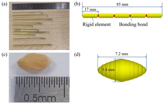
Figure 5.
Discrete element models of straw and wheat. (a) Straw length. (b) Discrete element model of straw. (c) Wheat seed. (d) Discrete element model of wheat seed.

Table 2.
Remaining contact parameters for discrete element simulation.
EDEM (Altair Engineering Inc., Troy, MI, USA) is an engineering simulation software based on the discrete element method. RecurDyn 2023 is a multibody dynamics software from FunctionBay, Inc. (Seongnam-si, Gyeonggi-do, Republic of Korea). The EDEM–RecurDyn coupled simulation was used to analyze the effect of double pressing on seeding depth caused by the press grooving roller and rear press roller. To reduce computational time, the model was simplified to focus exclusively on the single-row seeding process. Based on the parameters of the discrete element simulation, a soil bin model measuring 1000 mm × 225 mm × 450 mm was first established in EDEM. Subsequently, a straw layer corresponding to the amount of straw mulching was generated on the soil model surface, as illustrated in Figure 6a. The tillage depth of the double-shaft rotary cultivator was approximately 20 cm, resulting in a loose soil layer in the experiment field after rotary tillage. The penetration resistance of the soil layer was measured using a TJS-100 soil cone penetrometer (Figure 7a) (Shijiazhuang Fansheng Technology Co., Ltd., Shijiazhuang, China), with the measurement scenario illustrated in Figure 7b. During measurement, only the rotary tiller was mounted on the tractor, which operated in the middle of the plot. In the area after rotary tillage, soil penetration resistance was measured at 5 cm depth intervals from 0 to 20 cm. Five sampling locations were randomly selected within the tilled area, and the average value was taken as the soil penetration resistance after rotary tillage. The experiment was repeated three times, and the mean soil penetration resistance of the tilled field was found to be 390 kPa, indicating that the soil was relatively loose. To simulate the soil layer after rotary tillage, the double-shaft rotary tiller blade assembly model was imported into EDEM, with the tillage depth set to 20 cm. The constructed soil bin model was tilled once, resulting in the model illustrated in Figure 6b. The TJS-100 soil cone penetrometer was also modeled and imported into EDEM to measure the penetration resistance of the soil bin model at 5 cm intervals from 0 to 20 cm depth. The average measured value was 403 kPa, which is close to the penetration resistance of the field soil after rotary tillage.

Figure 6.
The soil bin model for pressing operations. (a) Before rotary tillage. (b) After rotary tillage.
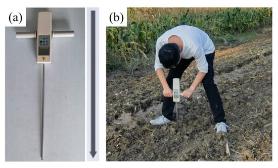
Figure 7.
Soil penetration resistance measurement method. (a) TJS-100 soil cone penetrometer. (b) Soil penetration resistance measurement.
Three joints are specified for the press grooving roller within the software: a vertical sliding joint, a horizontal sliding joint, and a rotational joint around the roller axis of rotation. Prior to the simulation, the mass of the press grooving roller was set according to the required compaction force. The press grooving roller was controlled by a step function. It underwent free fall onto the soil bin model from 0 to 0.6 s. It was uniformly accelerated to the forward speed from 0.6 to 0.7 s. It moved forward at a constant speed to form the seed furrow after 0.7 s. Figure 8a,b illustrate the interfaces of EDEM and RecurDyn during the simulation, respectively. Taking a forward speed of 4.5 km·h−1 as an example, the press grooving roller remains stationary and falls freely under the influence of gravity from 0 to 0.6 s until it contacts the soil surface. Between 0.6 and 0.7 s, the forward speed of the roller increases from 0 to 1250 mm·s−1 (4.5 km·h−1). After 0.7 s, the roller moves forward at a constant speed of 4.5 km·h−1.
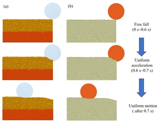
Figure 8.
DEM-MBD coupled simulation process of seed furrow formation by the press grooving roller. (a) EDEM simulation process. (b) RecurDyn simulation process.
After forming the seed furrow on the soil bin model, one hundred wheat seed models were randomly generated in the furrow using the particle factory in EDEM to simulate the seeding process. Subsequently, soil aggregate particles were generated to fill the furrow and slightly mound the surface to simulate soil covering, as illustrated in Figure 9. The DEM-MBD coupled simulation was then conducted, with the rear press roller set to the corresponding operating parameters to simulate the pressing process. The simulation procedure for the rear press roller was similar to that for the press grooving roller forming the seed furrow. After the double-pressing simulation was completed, five data collection sections were set in the post-processing module of EDEM, as illustrated in Figure 10. The distance from the seed to the soil surface was measured as the seeding depth.
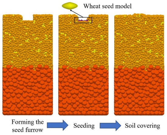
Figure 9.
Simulation process of wheat seeding.
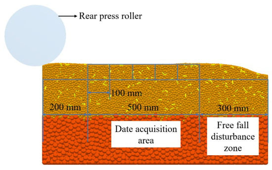
Figure 10.
Seeding depth data acquisition method.
2.3.2. Single-Factor Double-Pressing Simulation Experiment Design
Based on the above analysis, single-factor simulation experiments were first conducted using the protrusion height on the press grooving roller, forward speed, seed mass in the seed box, and straw mulching amount as experimental factors, with seeding depth as the evaluation index. The results of the single-factor experiments were then used to carry out CCD experiments. The levels of each experimental factor were determined according to actual field operating conditions, as shown in Table 3.

Table 3.
Levels of single-factor simulation experiments for double pressing.
2.4. DEM Simulation Experiments of Soil Covering
2.4.1. DEM Simulation Model of Soil Covering
During seed groove pressing simulations, the free fall motion of the press grooving roller induces disturbances on the soil bin model. To establish a soil bin model of sufficient length for soil covering simulation, a 2000 mm × 400 mm × 450 mm soil bin model was constructed with the straw mulching amount set at 0.6 kg m−2 based on double-pressing simulation results. The model was then subjected to rotary tillage. The mass of seeds in the seed box was set to the intermediate value after rotary tillage. The press grooving roller with a protrusion height of 29 mm was used to form the seed furrow. The central undisturbed 1000 mm section of the soil bin model was selected as the model for the soil covering simulation, as illustrated in Figure 11. The rotary tiller blades scatter soil backward in all directions during rotary tillage. The height of the BOX in EDEM was set equal to that of the soil bin model to realistically simulate the soil covering effect. The particles falling outside the computational domain during scattering were excluded from the simulation. Particles exiting the computational domain during soil throwing were deactivated in subsequent simulations.
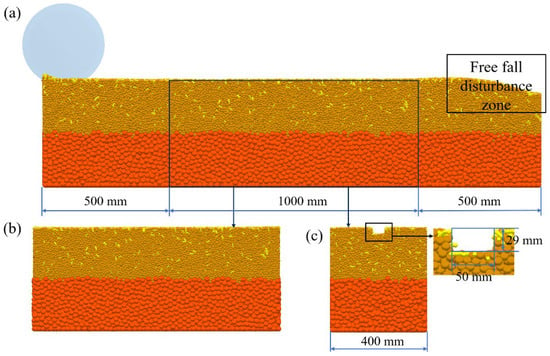
Figure 11.
The soil bin model for soil covering simulation. (a) Model extraction region. (b) Front view of the model. (c) Side view of the model.
Four rotary tiller blades were uniformly mounted on the tillage shaft within a single rotational plane, arranged in a helical pattern. Adjacent blades on the same helix were positioned at a 45° phase angle. This configuration improved the uniformity during the soil covering process. Six data acquisition zones were established at the center area of the soil bin model using EDEM’s post-processing module. The size of each zone was set to 40 mm × 50 mm × 100 mm based on soil covering simulation results. The mass of soil and fragmented straw within these zones was measured. The data acquisition method is illustrated in Figure 12.
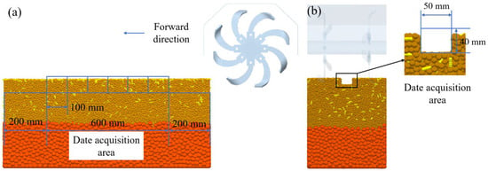
Figure 12.
Soil covering data acquisition method. (a) Front view. (b) Side view.
2.4.2. Single-Factor Simulation Experiments for Soil Covering
To analyze the soil-covering performance of rotary tiller blades under different operating conditions, single-factor simulation experiments were first conducted with rotary tiller blade working depth, rotational speed, and forward speed as experimental factors. Box–Behnken experimental design was subsequently implemented based on the results of these single-factor experiments. According to agronomic requirements for wheat cultivation, the soil should completely fill and slightly mound above the seed furrow after covering, and uniformity of soil coverage should be maintained throughout the process. Therefore, the mass of soil covering the seed furrow and the coefficient of variation in the soil-covering mass were selected as evaluation indices. The factor levels were determined according to field operating conditions and the requirements for rotary tiller blade shaft speed specified in national standard GB GB/T 5668-2017 “Rotary Tillers” [39], as shown in Table 4.

Table 4.
Experimental levels of single-factor simulation for soil covering.
The calculation formula for the coefficient of variation in the soil-covering mass is as follows:
where is the soil covering mass of the i-th measurement section; N is the total number of measurement sections; and is the mean soil covering mass across all measurement sections.
2.5. Field Experiment
To test the field performance of the double-shaft rotary tillage and double-press seeder, field experiments were conducted. The experimental field soil was alluvial, with a long-term rice-wheat rotation. The previous crop was rice, and after harvest, the straw was retained in the field, with a straw mulching amount of 0.93 kg·m−2. Five sampling locations were arranged in the experiment field. Soil samples were collected in layers at 5 cm intervals (0–5 cm, 5–10 cm, 10–15 cm, 15–20 cm) within the 0–20 cm soil layer using a ring knife. The measured average soil moisture content was 36.46% on a dry basis, and the average soil dry bulk density was 1.21 Mg·m−3.
The optimal seeding depth is 25 ± 5 mm according to local wheat cultivation agronomic requirements. The implement was operated with a seeding rate of 135 kg·ha−2. The seeding depth was measured following the method specified in the Chinese industry standard NY/T 996-2006 “Quality of Operation for Wheat Precision and Low-Rate Seeders” after operation [40]. Five measurement areas were selected at equal intervals along the diagonal, each with a width of one working width and a length of five working widths. In each measurement area, 10 sampling points were randomly selected, totaling 50 sampling points. The distance from the seed to the soil surface was measured at each point to calculate the average seeding depth and the qualified rate of seeding depth. The rear press roller device was removed from the implement to further assess the soil-covering performance. After the operation, three seeding rows were randomly selected in the experimental area. In each row, a 600 mm section was chosen and divided into six segments of 100 mm each. The soil and straw fragments covering the seeds in each segment were carefully collected, ensuring that the sampling location and area matched those used in the soil covering simulation. The mass of the collected soil and straw was weighed using an electronic balance, and the data were recorded to calculate the average soil-covering mass and its coefficient of variation.
The calculation formula for the mean sowing depth is as follows:
where is the sowing depth measured at the i-th measurement point, and N is the total number of the measurement points.
The calculation formula for the qualified rate of sowing depth is as follows:
where n is the number of sampling points with sowing depth within ±25 mm of the target value, and N is the total number of sampling points.
3. Results and Discussion
3.1. Results and Analysis of Double-Pressing Simulation Experiments
3.1.1. Analysis of Single-Factor Simulation Results for Double Pressing
The results of single-factor simulation experiments for double pressing are illustrated in Figure 13. When the forward speed, seed mass in the seed box, and straw mulching amount were kept constant, the seeding depth increased with the protrusion height on the press grooving roller. A greater protrusion height resulted in a deeper seed furrow. The seeding depth at a protrusion height of 25 mm was 71.42% of that at 35 mm, representing an increase of 8.65 mm, indicating that protrusion height has a significant effect on seeding depth. When protrusion height, seed mass in the seed box, and straw mulching amount were kept constant, the seeding depth increased with forward speed. At higher speeds, the press roller moves over the soil more quickly, so the soil is subjected to pressure for a shorter period of time. As a result, the soil experiences less compaction. In the simulation, the seeding depth at a speed of 1.5 km·h−1 was 5.2 mm less than that at 7.5 km·h−1 (i.e., only 84.44% of the depth at 7.5 km·h−1), demonstrating that forward speed significantly affects seeding depth.
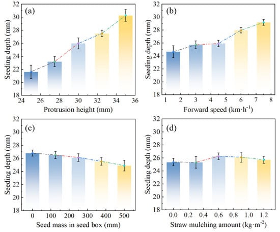
Figure 13.
Results of single-factor simulation experiments on seeding depth. (a) Different protrusion heights on the press grooving roller. (b) Different forward speeds. (c) Different seed mass in the seed box. (d) Different straw mulching amounts. Error bars represent standard deviation (SD) of the mean.
When protrusion height, forward speed, and straw mulching amount were kept constant, the seeding depth gradually decreased with increasing seed mass in the seed box. This is because, as the seed mass increases, the pressure exerted by the press grooving roller on the soil increases, resulting in greater soil compaction. The increased soil firmness after compaction makes further compaction by the rear press roller more difficult. At a seed mass of 500 kg, the seeding depth was 92.85% of that at 0 kg, a decrease of 1.92 mm. These experimental results indicate that the increase in seed mass led to only a slight reduction in seeding depth. When protrusion height, forward speed, and seed mass were kept constant, there was no clear trend in seeding depth with increasing straw mulching amount. The maximum difference in seeding depth was only 0.93 mm. This indicates that, after rotary tillage, changes in straw mulching amount in the soil–straw mixed layer had a minimal effect on seeding depth.
3.1.2. Central Composite Design (CCD) Simulation Experiment of Double-Pressing Seeding
The seed mass in the seed box was set to 250 kg and the straw mulching amount to 0.6 kg·m−2 based on the single-factor simulation experiment results. Protrusion height on the press grooving roller and forward speed were selected as experimental factors, with seeding depth as the response variable. The levels for the CCD simulation experiment are shown in Table 5, and the design and results of the CCD simulation experiment are presented in Table 6. H represents the protrusion height, V represents the forward speed, and B represents the seeding depth.

Table 5.
Experimental levels of CCD for double-pressing seeding.

Table 6.
Design and results of CCD experiment for double-pressing seeding.
The results of the variance analysis for seeding depth are shown in Table 7. As indicated by the analysis of variance (ANOVA), factors H, V, and their interaction HV had significant effects on seeding depth in the simulation experiment. The quadratic term H2 also had a significant effect, while V2 did not. A multiple regression analysis of the experimental results was conducted using Design Expert 13 software (Stat-Ease, Inc., Minneapolis, MI, USA), with non-significant terms from the variance analysis excluded. The resulting regression model for seeding depth is as follows:
B = −49.227 + 4.545H − 3.158V + 0.137HV − 0.072H2

Table 7.
ANOVA for the quadratic regression model of seeding depth in the CCD experiments.
These calculations are essential for accurately determining the significant factors affecting seeding depth and for constructing a robust predictive model, thereby providing a solid foundation for optimizing the seeding process and improving experimental reliability. The overall model was significant, and the lack-of-fit term was not significant. The coefficient of determination R2 was 0.99, and Radj2 was 0.98, indicating that the regression equation had a good fit and high reliability.
The field forward speed of the implement was set in the range of 1.5–7.5 km·h−1, and the target seeding depth was 25 mm. When the protrusion height was within the range of 27.5–32.5 mm, the seeding depth was closest to the target value of 25 mm. To obtain the optimal operating parameters, the parameter optimization constraint function was established as follows:
Using Design Expert to solve according to the parameter optimization constraints, the optimal protrusion height was found to be 28.54 mm and the optimal forward speed was 4.54 km·h−1. Considering manufacturing precision, the protrusion height was set to 29 mm. When the protrusion height was 29 mm and the forward speed was within 1.5–7.5 km·h−1, the seeding depth ranged from 23.3 to 27.3 mm, which meets the agronomic requirement of a seeding depth of 25 ± 5 mm.
3.2. Results and Analysis of Soil Covering Simulation Experiment
3.2.1. Results and Analysis of Single-Factor Simulation Experiment for Soil Covering
The results of the single-factor soil covering experiments are illustrated in Figure 14. During soil covering operations, it is required agronomically to ensure sufficient soil coverage without compromising seeding depth. Subsequently, a lower coefficient of variation of soil-covering mass should be pursued to ensure uniform filling of seed furrows. As the rotary tiller blade working depth increased, the mass of covering soil gradually increased, while the coefficient of variation of soil-covering mass first decreased and then increased. This is because a greater working depth results in more soil being thrown by the rotary tiller blade, thus increasing the mass of covering soil. When the working depth was 20–30 mm, the mass of covering soil was relatively small and the coefficient of variation was large, indicating that under these conditions, the seed furrow could not be completely filled and the uniformity of soil covering was poor, which does not meet agronomic requirements. When the working depth was 50–60 mm, the mass of covering soil was relatively high and the coefficient of variation was large. Although the seed furrow could be completely filled under these conditions, the uniformity of soil covering was poor.

Figure 14.
Results of single-factor experiments for soil covering operation. (a) Rotary tiller blade working depth. (b) Rotary tiller blade rotational speed. (c) Forward speed.
The mass of covering soil increased with the rotary tiller blade rotational speed, while the coefficient of variation of soil-covering mass decreased as the rotary tiller blade rotational speed increased. This is because as the rotary tiller blade rotational speed increases, the frequency between the blades and the soil also increases, resulting in a greater amount of soil being thrown per unit time, which increases the soil covering mass. At the same time, higher blade rotational speeds lead to more uniform soil disturbance, with more stable directionality and distribution of thrown soil, reducing spatial variability and thus lowering the coefficient of variation. When the rotary tiller blade rotational speed was 150–200 r·min−1, the soil-covering mass was small and the coefficient of variation was large, indicating poor soil covering quality under these conditions. When the rotary tiller blade rotational speed was 300–350 r·min−1, the soil-covering mass was relatively high and the coefficient of variation was relatively low, indicating that the soil-covering performance was optimal under these conditions.
The mass of covering soil first increased and then decreased with an increase in forward speed, while the coefficient of variation increased with forward speed. This is because as forward speed increases, the relative movement speed of the rotary tiller blade with respect to the soil increases, enhancing the disturbance of the soil by the blades and changing the amplitude and distance of soil throwing, which affects the amount of soil falling into the seed furrow. When the forward speed was around 4.5 km·h−1, the mass of soil falling into the seed furrow was at its maximum, indicating that the amplitude and distance of soil throwing were optimal at this speed. As the forward speed continued to increase, the relative time for the rotary tiller blade to cut the soil decreased, resulting in uneven soil disturbance, increased fluctuation in the amount of soil thrown, reduced stability, and a higher coefficient of variation of soil-covering mass.
3.2.2. Soil Covering Box–Behnken Design (BBD) Simulation Experiments
Based on the results of the single-factor simulation experiments for soil covering, the factor levels for the BBD simulation experiment were determined as shown in Table 8. The design and results of the BBD simulation experiment are presented in Table 9.

Table 8.
Experimental levels of BBD for soil covering.

Table 9.
Design and results of BBD experiment for soil covering.
The results of the variance analysis for soil-covering mass are shown in Table 10. According to the variance analysis, factors L, N, and V had significant effects on the soil-covering mass, while the interactions LN, LV, and NV had no significant effects. The quadratic terms L2, N2, and V2 had significant effects on the soil-covering mass. The regression model for soil-covering mass was obtained by performing multiple regression analysis of the experimental results in Design Expert, with non-significant terms excluded based on the analysis of variance, as follows:
M = −616.480 + 8.468L + 2.527N + 46.041V − 0.062L2 − 0.004N2 − 5.185V2

Table 10.
ANOVA for the quadratic regression model of soil-covering mass in the BBD experiments.
The overall model was significant, and the lack-of-fit term was not significant. The coefficient of determination R2 is 0.99, and the adjusted Radj2 was 0.98, indicating that the regression equation had a good fit and high reliability.
The ANOVA results for the coefficient of variation of soil-covering mass are shown in Table 11. According to the table, factors L, N, V, NV, L2, N2, and V2 had significant effects on the coefficient of variation of soil-covering mass, while LN and LV had no significant effects. Using Design Expert to perform multiple regression analysis on the experimental results and removing the non-significant terms identified in the ANOVA, the regression model for the coefficient of variation of soil-covering mass is obtained as follows:
CV = 1.1590 − 0.400L + 0.106N + 2.991V − 0.005NV + 0.007L2 − 0.0002N2 + 0.502V2

Table 11.
ANOVA for the quadratic regression model of the coefficient of variation of soil-covering mass in the BBD experiment.
The overall model was significant, and the lack-of-fit term was not significant. The coefficient of determination R2 was 0.99, and the adjusted Radj2 was also 0.99, indicating that the regression equation had a good fit and high reliability.
In order to obtain the optimal operating parameters for the rotary tiller blades, a multi-objective optimization method was adopted to optimize the factors affecting the soil covering mass and its coefficient of variation. Within the target range, the principle of increasing the soil covering amount and reducing its coefficient of variation was followed. The parameter optimization constraint functions were established as follows:
Using Design Expert to solve according to the parameter optimization conditions, the optimal rotary tiller blade working parameters were obtained as follows: optimal working depth of 55.3 mm, optimal rotational speed of 350 r·min−1, and optimal forward speed of 3.2 km·h−1. Under these conditions, the soil-covering mass was approximately 134.3 g, and the coefficient of variation for soil-covering mass was 8.88%.
3.3. Field Experiment Results
Based on the optimized operating parameters and considering machining accuracy, the actual protrusion height of the press grooving roller was set to 29 mm, and the rotary tiller blade working depth was set to 55 mm. The two-stage gearbox reduction ratios for the rotary tiller blade shaft were configured at 14:26 and 19:22. The rated engine speed of the tractor was 2200 r·min−1. The tractor PTO output speed was 760 r·min−1, resulting in an actual rotary tiller blade rotational speed of 353 r·min−1. The double-shaft rotary tillage and double-press seeder is illustrated in Figure 15a, the working process is illustrated in Figure 15b, the operational performance is illustrated in Figure 15c, and the measurement of seeding depth is illustrated in Figure 15d. The results of the field experiment are presented in Table 12. As shown in the table, with the increase in machine forward speed, the seeding depth gradually increased. The smaller seeding depth at the forward speed of 7.5 km·h−1 was due to insufficient soil covering. The qualified rate of seeding depth showed a decreasing trend; the soil-covering mass first increased and then decreased, while the coefficient of variation gradually increased, which was basically consistent with the simulation results. This is because as the forward speed increases, machine bumpiness intensifies, making the processes of forming seed furrows, soil covering, and pressing more unstable. Although the total weight of the seeder and seeds contributed to overall stability, field observations indicated that increased forward speed still resulted in greater machine bumpiness and process instability. Such instability at high forward speeds makes it difficult to maintain the quality of machine operation. Excessively high forward speed affects the uniformity and stability of seeding depth and soil covering, while too low a forward speed affects operational efficiency. Considering both operation quality and efficiency, 4.5 km·h−1 was determined to be the optimal forward speed for the seeder. At this speed, the seeding depth was approximately 25.7 mm, the qualified rate of seeding depth was 90%, the soil-covering mass was 143.2 g, and the coefficient of variation of soil-covering mass was 13.21%.
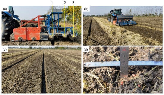
Figure 15.
Field experiment scenarios. (a) Double-shaft rotary tillage and double-press seeder: 1. press grooving roller; 2. soil covering device; 3. rear press roller. (b) Field experiment. (c) Field operation performance of the seeder. (d) Methodology for sowing depth measurement.

Table 12.
Results of the field experiment.
Wheat seeds of the Ningmai 13 variety were sown at a seeding rate of 135 kg·ha−1, with the application of 225 kg·ha−1 urea and 225 kg·ha−1 diammonium phosphate. The sowing operation was conducted at a speed of 4.5 km·h−1. Twenty days after sowing, the emergence of wheat seedlings was observed, as shown in Figure 16. The results showed that wheat seedlings emerged uniformly. Visual inspection of the sowing rows revealed no missing or broken seedlings. After uprooting, the root systems were observed to be intact, with the underground portion measuring approximately 25 mm, as shown in Figure 16b. Overall, the double-shaft rotary tillage and double-press seeder demonstrated good operational performance.
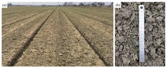
Figure 16.
Wheat emergence at 20 days after seeding. (a) Overall situation of wheat seedling emergence. (b) Wheat seedling.
4. Conclusions
- A double-shaft rotary tillage and double-press seeder was designed. Taking the protrusion height on the press grooving roller, forward speed, seed mass in the seed box, and straw mulching amount as experimental factors and seeding depth as the evaluation index, DEM-MBD coupled simulations were conducted. Both single-factor and CCD simulation experiments were carried out. The single-factor experiments determined the factors and levels for the CCD experiment. The protrusion height was found to be 29 mm according to the CCD simulation results.
- Taking rotary tiller blade working depth, rotational speed, and forward speed as experimental factors and soil covering mass and its coefficient of variation as evaluation indices, DEM simulations were performed. Single-factor experiments were first conducted. The BBD simulation experiment for soil covering was carried out based on the results of single-factor experiments. The optimal operating parameters for the rotary tiller blade were determined as a working depth of 55 mm and a rotational speed of 350 r·min−1.
- Field experiments were conducted based on the optimal parameter combinations. The results of the field experiments were basically consistent with the simulation experiments: the operational quality decreased with increasing forward speed. An operating speed of approximately 4.5 km·h−1 was found to be optimal for the implement, at which the average seeding depth was 25.7 mm, the seeding depth qualification rate was 90%, the soil covering mass within a 50 cm2 area was 143.2 g, and the coefficient of variation of soil covering mass was 13.21%.
The experiment field soil used in this study was alluvial soil, and the influence of rice stubble on operational quality was not considered. In the future, further research can be conducted on the effects of different soil types and different types of straw on seeding quality.
Author Contributions
Conceptualization, X.W. and Y.Z.; methodology, X.W. and Y.W.; software, X.W. and Y.S.; validation, J.D. and Y.W.; formal analysis, Y.W. and L.H.; investigation, J.D. and L.H.; resources, Y.S., R.Z. and X.X.; data curation, L.H., Y.W. and J.D.; writing—original draft preparation, X.W.; writing—review and editing, X.W., X.X. and Y.S.; supervision, Y.Z., X.X. and R.Z.; project administration, R.Z. and Y.Z.; funding acquisition, X.X. All authors have read and agreed to the published version of the manuscript.
Funding
This research was funded by the Jiangsu Modern Agricultural Machinery Equipment and Technology Demonstration and Promotion Project (NJ2025-02), the Science and Technology Project of Jiangsu Province (BE2022338), the Jiangsu Agriculture Science and Technology Innovation Fund (CX(24)1026), the Innovation Capacity Construction Project of Yangzhou University Jiangdu High-end Equipment Engineering Technology Research Institute (YDJD202506), and the High-end Talent Support Program of Yangzhou University.
Data Availability Statement
The original contributions presented in the study are included in the article; further inquiries can be directed to the corresponding authors.
Acknowledgments
The authors would like to thank the technical support of their teacher and supervisor. Additionally, we sincerely appreciate the work of the editor and the reviewers of the present paper.
Conflicts of Interest
The authors declare no conflicts of interest.
References
- Gutiérrez-Moya, E.; Adenso-Díaz, B.; Lozano, S. Analysis and vulnerability of the international wheat trade network. Food Secur. 2021, 13, 113–128. [Google Scholar] [CrossRef]
- Sawers, R.J.H.; Ramırez-Flores, M.R.; Olalde-Portugal, V.; Paszkowski, U. The impact of domestication and crop improvement on arbuscular mycorrhizal symbiosis in cereals: Insights from genetics and genomics. New Phytol. 2018, 220, 1135–1140. [Google Scholar] [CrossRef] [PubMed]
- Wang, Y.X.; Huang, S.T.; Zhang, W.Y.; Qi, B.; Zhou, X.Z.; Ding, Y.Q. Design and Experiment of Wheat Precision Seed Metering Device with Staggered Hook-tooth. Trans. Chin. Soc. Agric. Mach. 2024, 55, 142–153+167. (In Chinese) [Google Scholar]
- Ma, F.Y.; Wang, L.B.; Wang, C.; Wang, Q.J.; Lu, C.Y. Study on impact soil movement experiments on wheat seeds based on EDEM. Agriculture 2025, 15, 400. [Google Scholar] [CrossRef]
- Xia, J.F.; Wei, Y.S.; Zheng, K.; Liu, G.Y.; Liu, Z.Y.; Cheng, J.; Du, J. Design and experiment of multi-row uniform seeding control system for wide-row wheat seeder. Trans. Chin. Soc. Agric. Mach. 2024, 55, 145–156. (In Chinese) [Google Scholar]
- Wang, W.; Shi, W.; Liu, C.; Wang, Y.W.; Liu, L.; Chen, L.Q. Development of automatic wheat seeding quantity control system based on Doppler radar speed measurement. Artif. Intell. Agric. 2025, 15, 12–25. [Google Scholar] [CrossRef]
- Chaichi, M.; Ahmad Nemati, A.; Dadrasi, A.; Heydari, M.; Hassanisaadi, M.; Yousefi, A.R.; Baldwin, T.C.; Mastinu, A. Germination of Triticum aestivum L.: Effects of soil-seed interaction on the growth of seedlings. Soil Syst. 2022, 6, 37. [Google Scholar] [CrossRef]
- Li, Y.Y.; Qi, B.; Bao, E.C.; Tang, Z.; Lian, Y.; Sun, M.Y. Design and analysis of seeding depth detection and control device for multi-row wheat seeders adapted to different terrain variations. Agriculture 2025, 15, 290. [Google Scholar] [CrossRef]
- Parihar, D.S.; Dogra, B.; Narang, M.K.; Singh, S.K.; Khurana, R. Development and evaluation of notched concave disc seed drill for direct seeding of wheat in paddy stubble field. J. Agric. Food Res. 2022, 10, 100421. [Google Scholar] [CrossRef]
- Yatskul, A.; Lemiere, J.P. Establishing the conveying parameters required for the air-seeders. Biosyst. Eng. 2018, 166, 1–12. [Google Scholar] [CrossRef]
- Yin, M.N.; Wang, W.J.; Chen, Y.L.; Zhou, L.; Li, M.W. Design and test of a support cutting anti-clogging device with vibration for a no-till seeder. Eng. Agrícola 2025, 45, e20240115. [Google Scholar] [CrossRef]
- Malasli, M.Z.; Celik, A. Disc angle and tilt angle effects on forces acting on a single-disc type no-till seeder opener. Soil Tillage Res. 2019, 194, 104304. [Google Scholar] [CrossRef]
- Lu, Q.; Liu, L.J.; Liu, Z.J.; Jin, W.T. Design and experiment of star-tooth spherical disc soil-covering device for planter. Trans. Chin. Soc. Agric. Mach. 2024, 55, 23–31+73. (In Chinese) [Google Scholar]
- Yaseen, M.U.; Ahmad, S.; Ahmad, M.; Long, J.M.; Raza, H.A.; Iftekhar, H.; Ameer, S.; Ogunbiyi, D. A multi-function novel crop seeder for the management of residues and mechanized sowing of wheat in a single path. AgriEngineering 2024, 6, 2445–2469. [Google Scholar] [CrossRef]
- Li, C.S.; Tang, Y.L.; McHugh, A.D.; Wu, X.L.; Liu, M.; Li, M.; Xiong, T.; Ling, D.; Tang, Q.; Liao, M.; et al. Development and performance evaluation of a wet resistant strip-till seeder for sowing wheat following rice. Biosyst. Eng. 2022, 220, 146–158. [Google Scholar] [CrossRef]
- Bai, S.H.; Yuan, Y.W.; Wei, L.; Zhou, L.M.; Niu, K.; Zhao, B.; Zhang, J.H.; Wang, Y.Q.; Tong, W.Y.; Zhang, S.Y.; et al. Research on control system of electric-drive wheat shallow buried drip irrigation and wide-width precision seeder. INMATEH-Agric. Eng. 2024, 74, 81–94. [Google Scholar] [CrossRef]
- He, X.; Zhang, R.; Zhang, J.F.; Zhu, Y.H.; Wang, W.Z.; Zhang, H.M. Design and test of a double compression seeder for pre-sowing and seed furrow of wheat in wide-seedling belts. Int. J. Agric. Biol. Eng. 2024, 17, 136–145. [Google Scholar]
- Zhang, R.; Wei, J.T.; Zhang, D.X.; Cui, T.; Yan, B.X.; He, X.T.; Han, D.D.; Yang, L. Effects of wheat residue and depth-control mechanism of no-till seeder on corn sowing performance. Emir. J. Food Agric. 2018, 30, 660–667. [Google Scholar] [CrossRef]
- Xi, X.; Gu, C.J.; Shi, Y.J.; Zhao, Y.; Zhang, Y.F.; Zhang, Q.; Jin, Y.F.; Zhang, R.H. Design and experiment of no-tube seeder for wheat sowing. Soil Tillage Res. 2020, 204, 104724. [Google Scholar] [CrossRef]
- Xi, X.B.; Gao, W.J.; Gu, C.J.; Shi, Y.J.; Han, L.J.; Zhang, Y.F.; Zhang, B.F.; Zhang, R.H. Optimisation of no-tube seeding and its application in rice planting. Biosyst. Eng. 2021, 210, 115–128. [Google Scholar] [CrossRef]
- Wang, B.K.; Gu, F.W.; Hu, Z.C.; Wu, F.; Chen, X.L.; Luo, W.W. Analysis and evaluation of influencing factors on uniform sowing of wheat with wide seed belt after sowing and soil throwing device. Agriculture 2022, 12, 1455. [Google Scholar] [CrossRef]
- Zhao, P.F.; Ju, X.T.; Yang, P.K.; Zheng, Z.Q.; Huang, Y.X.; Gao, X.J.; Shi, J.T. Design and experiment of fertilizer pipe front-mounted wheat wide seedling belt rotary tillage fertilization planter. Trans. Chin. Soc. Agric. Eng. 2024, 40, 12–21. [Google Scholar]
- NY/T 1143-2006; Technical Specification for Quality Evaluation of Seeders. Ministry of Agriculture of the People’s Republic of China: Beijing, China, 2006. (In Chinese)
- Akhmetov, A.; Akhmedov, S.; Ishchanov, J. Investigating the Impact of Speed and Tire Pressure of a Wheel Tractor on Soil Properties: A Case Study in Northeastern Uzbekistan. AgriEngineering 2024, 6, 2067–2081. [Google Scholar] [CrossRef]
- Memon, M.S.; Guo, J.; Tagar, A.A.; Perveen, N.; Ji, C.Y.; Memon, S.A.; Memon, N. The effects of tillage and straw incorporation on soil organic carbon status, rice crop productivity, and sustainability in the rice-wheat cropping system of eastern China. Sustainability 2018, 10, 961. [Google Scholar] [CrossRef]
- Cheng, F.P.; Wang, X.G.; Guo, M.Z.; Zhao, J.L.; Li, M.J. A compacting device of rice dry direct-seeding planter based on DEM-MFBD coupling simulation significantly improves the seedbed uniformity and seedling emergence rate. Biosyst. Eng. 2024, 246, 26–40. [Google Scholar]
- Zhang, L.; Zhai, Y.B.; Wu, C.Y.; Huang, S.Z.; Zhang, Z.E. Modeling the interaction between a new four-bar subsoiling mechanism and red soil using the improved differential evolution algorithm and DEM. Comput. Electron. Agric. 2023, 208, 107783. [Google Scholar] [CrossRef]
- Ma, X.D.; Guo, B.J.; Li, L.L. Simulation and experiment study on segregation mechanism of rice from straws under horizontal vibration. Biosyst. Eng. 2019, 186, 1–13. [Google Scholar] [CrossRef]
- Zhao, W. Discrete Element Simulation and Improvement Design of Vehicular Unbundling-Spreading Device. Master’s Thesis, Northwest A&F University, Xianyang, China, 2021. (In Chinese). [Google Scholar]
- Wang, Q.R. Research on Intelligent Design Method of Threshing Device of Rice Combine Harvester. Ph.D. Thesis, Jiangsu University, Zhenjiang, China, 2020. (In Chinese). [Google Scholar]
- Wang, J.L. Optimum Design and Experimental of Rice Straw Deep-Buried Roller Assembly Based on Discrete Element Method. Master’s Thesis, Northeast Agricultural University, Harbin, China, 2019. (In Chinese). [Google Scholar]
- Wang, L.; Liao, Q.X.; Xi, R.J.; Li, X.R.; Liao, Y.T. Influence of an equal width polygon groove-tooth wheel on feeding performance of the seed feeding device for wheat. Comput. Electron. Agric. 2024, 217, 108565. [Google Scholar] [CrossRef]
- Makange, N.R.; Ji, C.Y.; Torotwa, I. Prediction of cutting forces and soil behavior with discrete element simulation. Comput. Electron. Agric. 2020, 179, 105848. [Google Scholar] [CrossRef]
- Yang, D.Z. Rice Straw Double Shaft Deep Burial Returning Machine Design and Test. Master’s Thesis, Northeast Agricultural University, Harbin, China, 2023. (In Chinese). [Google Scholar]
- Zhong, X.K. Design and Experiment of Key Components of Seed Ditch Reconstruction in Wheat Stripe Rotary Seeder. Master’s Thesis, Shandong University Of Technology, Zibo, China, 2023. (In Chinese). [Google Scholar]
- Ma, Z.T.; Zhao, Z.H.; Quan, W.; Shi, F.G.; Gao, C.; Wu, M.L. Calibration of discrete element parameter of rice stubble straw based on EDEM. J. Agric. Sci. Technol. 2023, 25, 103–113. (In Chinese) [Google Scholar]
- Zhang, J.; Ding, Y.; Yang, R.B.; Pan, Z.G.; Mu, J.; Wang, W.J.; Liu, Q.; Wang, S.A. Parameter calibration for discrete element simulation of cutting deck cleaning in small plot wheat combine harvester. INMATEH Agric. Eng. 2024, 72, 339–351. [Google Scholar] [CrossRef]
- Zhou, Y.; Shang, W.Y.; Hui, Y.B.; Shi, C.; Gao, J.; Zhang, Y.Z.; Liu, J.J.; Cheng, D.D.; Zhu, K. Construction of an accurate wheat-grain model based on X-ray tomography and bonding parameters by discrete element. Appl. Sci. 2023, 13, 9265. [Google Scholar] [CrossRef]
- GB/T 5668-2017; Rotary Tillers. National Standard of the People’s Republic of China: Beijing, China, 2017.
- NY/T 996-2006; Quality of Operation for Wheat Precision and Low-Rate Seeders. Chinese Agricultural Industry Standard: Beijing, China, 2006.
Disclaimer/Publisher’s Note: The statements, opinions and data contained in all publications are solely those of the individual author(s) and contributor(s) and not of MDPI and/or the editor(s). MDPI and/or the editor(s) disclaim responsibility for any injury to people or property resulting from any ideas, methods, instructions or products referred to in the content. |
© 2025 by the authors. Licensee MDPI, Basel, Switzerland. This article is an open access article distributed under the terms and conditions of the Creative Commons Attribution (CC BY) license (https://creativecommons.org/licenses/by/4.0/).