Article

Design and Analysis of a Sowing Depth Detection and Control Device for a Wheat Row Planter Based on Fuzzy PID and Multi-Sensor Fusion

1
Key Laboratory of Modern Agricultural Equipment, Ministry of Agriculture and Rural Affairs, Nanjing Institute of Agricultural Mechanization, Nanjing 210014, China
2
School of Agricultural Engineering, Jiangsu University, Zhenjiang 212013, China
3
The Agriculture Ministry Key Laboratory of Agricultural Engineering in the Middle and Lower Reaches of Yangtze River, Institute of Agricultural Facilities and Equipment, Jiangsu Academy of Agricultural Sciences, Nanjing 210014, China
4
College of Transportation Engineering, Jiangsu Shipping College, Nantong 226010, China
*
Authors to whom correspondence should be addressed.
Agronomy 2025, 15(6), 1490; https://doi.org/10.3390/agronomy15061490
Submission received: 23 May 2025 / Revised: 17 June 2025 / Accepted: 18 June 2025 / Published: 19 June 2025
(This article belongs to the Section Precision and Digital Agriculture)

Abstract

A bench test apparatus was developed to address the impact of varying terrain undulation on sowing depth in multi-row wheat sowing machines. In addition, a real-time sowing depth control model was proposed and implemented, enabling automatic adjustment of the sowing depth and ensuring uniform seed placement. The model operates by first specifying a target sowing depth, then acquiring real-time sowing depth measurements via a laser range sensor and terrain feature data ahead of the machine via an array-based LiDAR sensor. These two data streams undergo multi-sensor fusion to produce an accurate error and error rate. A fuzzy PID control algorithm then performs online parameter tuning of the PID gains, generating the control output needed to drive the stepper motor and adjust the depth-limiting wheel height, thereby precisely regulating the sowing depth. Experimental results demonstrate that under representative test conditions, the system achieves excellent sowing depth control performance; average error reductions of 10.7%, 22.9%, and 9.6% were observed when using fuzzy PID control versus no control. This work provides a technical foundation for intelligent sowing depth control in wheat sowing machines and lays the groundwork for future in-field adaptive operation and multi-scenario integrated control.

1. Introduction

Sowing depth is a critical agronomic parameter in wheat planting, as it directly determines the degree of seed–soil contact and thus influences water and nutrient uptake by the seedling [1]. An optimal sowing depth promotes rapid germination, healthy root development, and ultimately increased yield. If the sowing depth is too shallow, seeds may be dislodged by wind, water, or wildlife; if it is too deep, emergence may be delayed or inhibited [2]. Therefore, maintaining consistent and accurate sowing depth is essential for improving wheat production efficiency [3].
In field operations, soil properties and terrain are rarely uniform. Terrain undulation and terrain slope can destabilize the sowing machine and introduce sowing depth deviations. Experiments have shown that on undulating terrain, conventional fixed-parameter depth-limiting systems yield uneven seed placement, complicating field management [4]. Moreover, traditional single-point sensors often fail to track abrupt or non-uniform ground changes in real time, posing a significant challenge for sowing depth detection [5].
Non-contact sensing technologies have become key enablers of closed-loop sowing depth control by providing instantaneous feedback. Early studies explored various approaches to enhance detection accuracy and reliability [6]. For example, Mapoka et al. used ground-penetrating radar to non-intrusively locate corn seeds in closed trenches and estimate their planting depth from radar echoes [7]. Nielsen et al. combined a linear displacement sensor (measuring the furrow opener’s position relative to the machine frame) with an ultrasonic sensor (measuring the frame’s height above the ground), fusing both signals to compute the actual furrow depth [1]. Lee et al. developed a hybrid system that integrates optical range measurements, pitch angle monitoring, and lift-arm position sensing; by fusing these data through a mathematical model, they achieved precise cultivation-depth estimation [8]. These multi-sensor fusion strategies consistently outperformed single-sensor solutions across varied terrain conditions, providing important reference points for high-precision sowing depth control system design.
Common sowing depth detection methods—such as ultrasonic ranging, mechanical displacement estimation, and auxiliary measurement—still suffer from limited precision, response lag, and drift under harsh field conditions [9]. Consequently, selecting sensors with fast response time and strong robustness is foundational for accurate depth control [10].
In this study, we employ two complementary sensors to construct our sowing depth detection module. First, the STP-23L laser range sensor offers a compact form factor, high resolution, and strong anti-interference performance. Based on time-of-flight (ToF) principles, it measures the pulse travel time of infrared lasers to compute the vertical distance between the depth-limiting wheel and the soil surface with millimeter-level accuracy and high refresh rates, making it well suited for real-time in-field monitoring [11]. Second, the P8864-SMD-B15 array-based LiDAR sensor houses an 8×8 infrared ToF depth array, capturing 64 high-resolution range points in parallel to reconstruct the three-dimensional terrain ahead of the sowing machine. Unlike single-point sensors, this array-based LiDAR sensor delivers richer spatial detail and robust performance under uneven soil or residue-covered conditions. Its depth matrix enables feed-forward compensation of upcoming terrain undulations, enhancing overall control accuracy [12].
Regarding control strategy, although fixed-parameter PID control can yield satisfactory results in relatively stable environments, it struggles to accommodate the nonlinearities and uncertainties inherent in complex field conditions [13]. Fuzzy PID control, by contrast, offers nonlinear mapping and enhanced robustness, making it ideal for scenarios with model uncertainty, discontinuous disturbances, or rapidly changing terrain [14]. In our implementation, baseline PID gains Kp, Ki, and Kd are first configured based on prior experience; the fuzzy PID controller then continuously refines these gains according to the real-time error and error rate, achieving adaptive, flexible control [15]. Both Simulink simulations and indoor bench test platform experiments demonstrate that this hybrid approach significantly improves disturbance rejection and response stability under representative terrain profiles [16,17].
In summary, this research presents a sowing depth control system that integrates multi-sensor fusion with fuzzy PID control. By merging real-time sowing depth data from the laser range sensor and terrain feature data from the array-based LiDAR sensor, the system computes an accurate fused error and error rate, which drives online parameter tuning of the PID gains. This enables rapid compensation for both current sowing depth deviations and anticipated terrain fluctuations, delivering a robust, reliable solution for consistent sowing depth control across diverse field conditions.

2. Material and Methods

2.1. Materials and Test Equipment

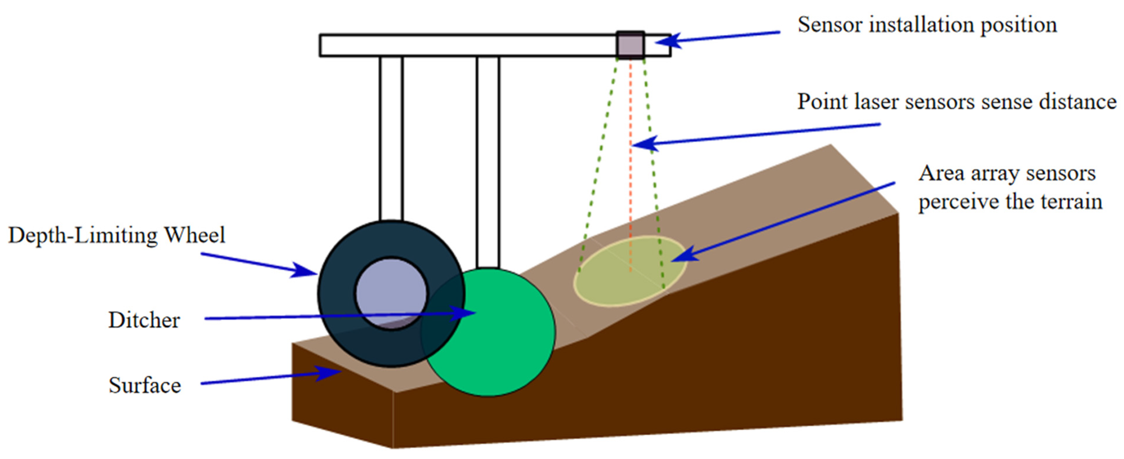
2.1.1. Principle of Sowing Depth Detection

Accurate sowing depth detection is fundamental to achieving uniform emergence and ensuring crop yield, as it relies on dual perception of the depth-limiting wheel position and the current terrain undulation to generate a reliable real-time depth reference and apply dynamic corrections based on local terrain features [18]. Traditional methods typically rely on fixed mechanical setups that cannot adapt to environmental disturbances or terrain variability, leading to significant depth deviations. To overcome this limitation, the proposed system employs a multi-sensor fusion strategy combining a laser range sensor and an array-based LiDAR sensor. These non-contact, high-precision sensors, respectively, provide the baseline sowing depth measurement and a terrain slope correction term, yielding a detection system with both real-time responsiveness and high robustness.
The laser range sensor measures the time of flight (ToF) of an emitted laser pulse reflected from the soil surface and received back at the sensor. By subtracting this measured distance from the known installation height of the sensor above the depth-limiting wheel, the system continuously outputs the vertical distance L′ between the wheel’s bottom and the soil surface in real time [18]. Due to its high sampling rate and millimeter-level accuracy, this distance can be directly used as the baseline sowing depth,
d b a s e = L ,
which is updated continuously during operation to provide uninterrupted feedback.
The array-based LiDAR sensor captures a three-dimensional point cloud of the small region directly ahead of the depth-limiting wheel (the upcoming sowing path). Its 8 × 8 pixel array produces a raw depth matrix Zi,j. After applying filtering, local gradient extraction, and normalization, the system derives a terrain correction term Δ d terrain that quantifies the forthcoming soil undulation [19]:
Δ d terrain = f ( Z i , j )
where f(·) encompasses the sequence of data processing steps, including denoising, gradient computation, and principal component feature extraction.
The final real-time sowing depth d is obtained by summing the baseline depth and the terrain correction:
d = d b a s e + Δ d t e r r a i n
Figure 1 illustrates the detection workflow, showing the mounting positions of both sensors, the laser ranging direction, and the LiDAR scanning field of view, which together demonstrate the system’s capability to simultaneously track soil surface geometry and machine pose.
By fusing high-accuracy ToF measurements from the laser range sensor with the spatial feature-rich data from the array-based LiDAR sensor, the system not only captures the instantaneous wheel-to-soil distance but also anticipates and compensates for upcoming terrain undulation. This enables dynamic adjustment of the sowing depth setting, ensuring precise, stable seed placement across variable field conditions.

2.1.2. Analysis of the Principle of Traditional PID Control and Its Applicability

PID control is a classical linear control method widely used in both open-loop and closed-loop feedback systems. It adjusts the control output through feedback based on the proportional (P), integral (I), and derivative (D) components of the control error. This approach has been extensively applied in the field of agricultural machinery control [20]. The basic control principle of PID is illustrated in Figure 2.
The continuous-time control expression is given by
u ( t ) = K p e ( t ) + K i 0 t e ( τ ) d τ + K d d e ( t ) d t
where the parameters are defined as follows:
u(t): Control output;
e(t): Control error, defined as the difference between the setpoint and the actual value;
Kp: Proportional gain;
Ki: Integral gain;
Kd: Derivative gain;
0 t e ( τ ) d τ : Integral of the error over time, used to eliminate steady-state error;
d e ( t ) d t : Derivative of the error, used to anticipate system trends, improve response time, and suppress oscillations.
In sowing depth control, the proportional term generates immediate corrective action based on the current error, the integral term accumulates past errors to eliminate steady-state bias, and the derivative term forecasts the error trend to reduce overshoot and dampen oscillations [21]. However, conventional PID controllers typically rely on fixed parameters, which limit their adaptive capability when dealing with nonlinear systems or abrupt environmental changes. In scenarios involving significant terrain undulation or frequent sowing depth variation, fixed-parameter PID often leads to excessive overshoot, oscillation, or even system instability [22]. Therefore, it is necessary to introduce more flexible control strategies to enhance system adaptability and robustness under complex working conditions.

2.1.3. PID Controller Parameter Tuning Methods

The tuning of PID controller parameters is a critical step in achieving desirable dynamic and steady-state system performance. In general, tuning approaches are classified into two major categories: theoretical computation methods and engineering empirical methods.
Theoretical methods rely on accurate mathematical models of the system. These approaches use tools such as frequency domain analysis (e.g., gain and phase margin), pole placement techniques, or optimization algorithms such as least squares, linear quadratic regulators (LQRs), and particle swarm optimization to derive the optimal values for Kp, Ki, and Kd. While these methods can yield high-performance tuning results when accurate models and sufficient computational resources are available, they require a precise system model, which may not always be feasible in practice.
Engineering empirical methods are more widely applied in real-world control systems, as they do not depend on an exact mathematical model. The most common techniques include:
Trial-and-error method: This approach involves initially selecting parameter values based on experience, followed by iterative fine-tuning of the proportional, integral, and derivative components. System behavior such as overshoot, response time, and steady-state error is observed and adjusted accordingly. While simple and intuitive, this method is time-consuming and heavily reliant on the operator’s expertise.
Ziegler–Nichols ultimate gain method: In this method, the integral and derivative actions are disabled, leaving only the proportional loop active. The proportional gain Kp is gradually increased until the system reaches sustained oscillations. The corresponding gain is called the ultimate gain Ku, and the oscillation period is the ultimate period Tu. PID parameters are then calculated using empirical formulas (e.g., the Ziegler–Nichols tuning table). This method is suitable when a fast response and acceptable overshoot are desired.
Damped oscillation method: Similar to the ultimate gain method, this technique seeks to induce damped oscillations with a specific decay ratio (e.g., 4:1 or 10:1). The observed decay characteristics and oscillation period are used to compute the PID parameters. This approach offers a better balance between fast response and overshoot suppression and is well suited for scenarios requiring minimal steady-state error.

2.1.4. Fundamentals of Fuzzy Control Theory

Fuzzy control is a rule-based technique grounded in fuzzy set theory and linguistic logic. It is particularly effective for systems with incomplete models or parameter uncertainties, where classical control strategies may struggle to maintain performance [23]. Unlike conventional PID control, which relies on precise mathematical modeling, fuzzy control operates by defining fuzzy sets for input variables, constructing appropriate membership functions, and establishing a rule base composed of expert-defined “IF–THEN” statements. This structure allows the system to perform inference and generate control actions based on qualitative reasoning [24].
Fuzzy control systems generally consist of three core components: fuzzification, inference, and defuzzification. First, numerical inputs (such as the error, eee, and error rate, ececec) are converted into qualitative fuzzy variables, e.g., “negative big” “negative small”, and “zero”. Second, using the rule base, the fuzzy controller performs logical inference to determine the fuzzy output. Finally, a defuzzification process converts the inferred fuzzy output (such as the adjustments ΔKp, ΔKi, ΔKd) into concrete numerical values that can be used in real-time control [25].
One of the major advantages of fuzzy control is that it does not require a precise mathematical model of the system. As a result, it offers strong adaptability and robustness in complex environments with disturbances and uncertainties, making it especially suitable for sowing depth control applications [26].
Fuzzy PID control integrates the advantages of both traditional PID control and fuzzy logic, enabling real-time adjustment of PID parameters through fuzzy inference. This enhances the system’s adaptability to nonlinear dynamics and uncertain operating environments.
K p = K p + Δ K p K i = K i + Δ K i K d = K d + Δ K d
The parameters Kp, Ki, and Kd represent the preset PID gains, while the adjustment terms ΔKp, ΔKi, and ΔKd are dynamically computed by the fuzzy controller in real time.

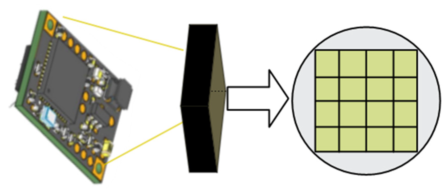
2.1.5. Design, Implementation and Calibration of Sensor Module

In the sowing depth control system, the sensor module plays a pivotal role in environmental perception, directly influencing the system’s ability to respond to terrain undulation and maintain precise sowing depth control [27]. This system integrates two high-performance non-contact sensing devices: the P8864-SMD-B15 array-based LiDAR sensor and the STP-23L laser range sensor. Both are mounted at the front end of the sowing machine chassis to enable real-time acquisition of ground elevation and terrain profile information.
The P8864-SMD-B15 is a compact 3D time-of-flight (ToF) sensor module, as illustrated in Figure 3. It features an 8 × 8 pixel array capable of capturing detailed 3D representations of the ground surface, making it suitable for detecting subtle undulations and complex terrain structures. This module provides both depth and intensity data for each pixel and supports a measurement range of up to 5 m, enabling use in both indoor and outdoor settings. Additionally, it incorporates calibration compensation and distance-adaptive algorithms and can optionally embed AI models—such as depth-based gesture or posture recognition—using onboard computation [28].
The STP-23L laser range sensor operates on the same ToF principle, measuring the time interval between laser emission and reflection to compute the distance to the ground surface. It offers high measurement accuracy and fast response times, making it ideal for real-time distance acquisition between the sensor and the soil. The STP-23L integrates laser emission, reception, and signal processing within a compact housing and is well suited to a variety of ranging applications. Its structural configuration is shown in Figure 4.
Data collected by both sensors are transmitted to the host computer via a data acquisition module, where fusion processing is performed to enhance both the accuracy and robustness of terrain perception. The sensor module is secured to the front of the sowing machine using a dedicated mounting bracket, which is specifically designed to ensure a wide fild of view and resistance to vibration, thereby enabling stable and accurate data collection during field operations. The communication between the sensor module and the host computer is implemented via wired interfaces using standardized protocols to ensure real-time and reliable data transfer [29].
The performance parameters of the array-based LiDAR sensor and the laser range sensor are detailed in Table 1 and Table 2, respectively.
In order to verify the ranging accuracy of the planar sensor, in the early stage of this research, the P8864-SMD-B15 type planar laser radar sensor (Shenzhen Senkulesa Intelligent Technology Co., Ltd., Shenzhen, China) was calibrated in the laboratory environment. Experiments were conducted under three experimental scenarios (flat surface without straw, surface covered with straw, and slope change), and corresponding influence results were obtained. The test results show that the coverage of straw has a relatively small impact on the measurement values of the laser sensor and the planar sensor. Even in an inclined terrain, the planar sensor can still accurately capture the undulating features of the terrain. By analyzing the error changes of the planar sensor when the measurement distance gradually increased from 200 mm to 500 mm, it was found that the measurement error gradually increased with the increase in distance, as shown in Figure 5 [30].

2.1.6. Depth-Limiting Mechanism and Stepper Motor Control System

In modern agricultural sowing operations, the control of sowing depth is not only critical for uniform seedling emergence but also significantly influences plant spacing and population structure throughout the growing period. It serves as a key component of precision agriculture. In field environments characterized by complex topography and varying surface conditions, traditional mechanical or manual depth adjustment methods are no longer sufficient to meet real-time accuracy requirements. To address the challenges posed by irregular terrain and heterogeneous soil conditions, this system adopts a dynamic adjustment mechanism based on the coordinated operation of a depth-limiting wheel and a stepper motor. By integrating real-time terrain sensing and a fuzzy PID control algorithm, the system enables closed-loop regulation of sowing depth, ensuring uniform and optimal seed placement [31].
The depth-limiting mechanism consists of a depth-limiting wheel, a stepper motor, a lead screw transmission assembly, and a supporting structure. The stepper motor drives the lead screw to raise or lower the depth-limiting wheel, thereby adjusting the working depth of the sowing machine. This design features a simple structure, fast response, and high control accuracy, making it suitable for variable and complex field conditions.
In terms of control architecture, the stepper motor is managed by a centralized host computer system that issues depth adjustment commands. The host computer receives real-time terrain data from the front-mounted sensors, including ground height measurements from the laser range sensor and terrain correction data from the array-based LiDAR sensor. It then calculates the sowing depth error based on the difference between the target and measured depth. This error, along with its rate of change (e and ec), serves as input to the fuzzy PID controller. The controller uses fuzzy inference and rule-based logic to adjust the PID parameters dynamically and generate a control signal to drive the stepper motor, thereby achieving real-time, closed-loop depth regulation [32]. Figure 6 sequentially illustrates the stepper motor, gear reducer, stepper driver, and power supply, which together form a complete electrical actuation chain.
In practical applications, the resolution of sowing depth adjustment is determined by the step angle of the motor and the lead screw pitch.

2.1.7. Overall Structure and Integration of the Sowing Machine

Based on a comprehensive 3D CAD model, a multi-row wheat sowing machine was developed with a compact structure and integrated functionality, suitable for a variety of field environments. The main components of the machine include the frame, furrow opener, depth-limiting wheel, seed hopper, metering device, and press wheel assembly. These units work in coordination to ensure efficient and precise sowing.
As shown in Figure 7a, the frame serves as the structural backbone, supporting and connecting all functional modules. It is designed with sufficient stiffness and strength to handle diverse operating conditions. Figure 7b shows the furrow opener, which is responsible for forming seed trenches in the soil. Various opener types exist, including cone-shaped, disc, and shovel types [33]; disc openers are particularly effective under straw-covered conditions due to their superior cutting ability, making them adaptable to different soil types.
The depth-limiting wheel ensures uniformity and stability in sowing depth. In this design, it is integrated with a stepper motor and gear reducer to enable precise sowing depth regulation. Figure 7c displays the seed hopper, which stores the seeds to be sown. Its capacity is designed to meet the requirements of continuous operation and reduce downtime for seed refilling. The metering device delivers seeds at a controlled and uniform rate; a gravity-based mechanism is used for its simplicity and reliability.
Located at the rear, Figure 7d shows the press wheel assembly, which covers and compacts the soil after seeding. This component ensures good seed–soil contact, thereby promoting germination. The press wheels are carefully designed to distribute pressure evenly and maintain effective seedbed compaction [34].
The configuration parameters of this multi-row wheat sowing machine are shown in Table 3 as follows:

2.2. Test Method

2.2.1. Software Architecture of the System

The software part of the sowing depth control system is mainly deployed on the host computer platform, which is used to implement real-time data acquisition, preprocessing, execution of the fuzzy PID control algorithm, and closed-loop feedback control. The overall software architecture of the system forms a complete closed-loop control system, in which both data flow and control processes reflect the entire procedure from acquiring field data to generating control signals and then driving the actuator to adjust the sowing depth [35].
Specifically, the host computer receives real-time data from the hardware components (sensor module, stepper motor feedback) through standard interfaces. The data acquisition module first collects and preliminarily processes raw data from the laser range sensor and the array-based LiDAR sensor, which is then transferred to the data-processing module [36]. In this module, the software performs filtering, smoothing, and normalization processing on the received data to ensure that the data used meets the accuracy requirements for control. Meanwhile, the host computer software constructs the overall system flow diagram, covering data acquisition, preprocessing, fuzzy PID algorithm implementation, and feedback control. The fuzzy PID controller, based on the preset membership functions and rule base, processes the input fused sowing depth error value and its rate of change, obtains dynamic adjustment values, and then adds them to the base PID parameters to generate the final control output. This output signal is transmitted to the lower-level controller via the data communication interface to drive the stepper motor and adjust the depth-limiting wheel, thereby realizing real-time adjustment of the sowing depth. Finally, the host computer interface visually displays real-time data and control status [37].
To facilitate a more intuitive understanding of the dynamic characteristics of the sowing depth control system and the relationships among its control components, a simplified schematic diagram of the system’s dynamic modeling is provided in Figure 8.

2.2.2. Data Acquisition and Preprocessing

In the host computer software, the data acquisition and preprocessing module serves as the data foundation of the entire control system, and its main task is to convert the signals from hardware sensors into high-quality data suitable for subsequent processing and control analysis. The specific process is as follows:
First, the system receives digital signals transmitted in real time from the laser range sensor and the array-based LiDAR sensor. The laser range sensor mainly measures the distance between the sowing machine and the soil surface, while the array-based LiDAR sensor captures three-dimensional information of the terrain ahead. These raw data are often affected by environmental interference, noise, and data discreteness. To ensure data accuracy, the host computer software adopts a series of signal preprocessing methods. The preprocessing process includes applying median filtering and moving average methods to smooth the collected signals and filter out occasional noise. Meanwhile, normalization is performed to unify the scale of data from each sensor to facilitate subsequent fusion processing [38].
After preprocessing, the software further extracts features from the processed data, focusing mainly on terrain data obtained from the array-based LiDAR sensor. Local gradient calculation and principal component analysis (PCA) methods are employed to extract key terrain features (such as average slope and standard deviation) [39,40]. These feature data are combined with the sowing depth data directly measured by the laser range sensor and are processed through a fusion algorithm to compute the comprehensive error value e and its rate of change ec, which serve as the input signals for the subsequent fuzzy PID controller. The interface of the host computer control software is shown in Figure 9.

2.2.3. Sowing Depth Error Calculation and Data Fusion

The precise control of sowing depth depends on the accurate acquisition and processing of actual field data. This section describes how the host computer software calculates the sowing depth error through data acquisition, preprocessing, and fusion, providing reliable inputs for the control algorithm.
First, the laser range sensor is used to obtain the real-time distance data p between the sowing machine and the soil surface. These data directly reflect the current sowing depth. Correspondingly, the preset sowing depth d is input into the system as the target value. The difference between the two is defined as the initial error elaser:
e laser = p d
where p represents the average distance data acquired by the laser range sensor, d represents the preset sowing depth, and elaser represents the initial error of the current sowing depth.
Meanwhile, the array-based LiDAR sensor collects a set of two-dimensional data reflecting terrain undulations. After filtering and normalization, the data are processed using local gradient calculation to obtain the terrain error information earray. To enhance robustness and accuracy, the host computer fuses the error signals from the laser range sensor and the array-based LiDAR sensor to compute the comprehensive error value e:
e = e laser e array
where elaser represents the initial error obtained from the laser range sensor data, earray represents the correction value obtained from the array-based LiDAR sensor, and eee is the final comprehensive error value.
In addition, to capture the dynamic changes in sowing depth, the host computer also performs time difference calculation on the fused error value to obtain the error rate of change ec:
ec = e ( t + Δ t ) e ( t ) Δ t
After preprocessing and fusion, the values eee and ececec serve as the direct inputs for further fuzzy PID control on the host computer, ensuring that the control algorithm can accurately reflect the deviation and variation trend of the sowing depth in real time. This in turn guides the lower-level drive system to adjust the height of the depth-limiting wheel and realize closed-loop control.

2.2.4. Design of the Fuzzy PID Control Algorithm

The fuzzy PID controller designed in this study is a two-dimensional fuzzy controller, and its design process can be divided into the following steps [41].
(1)
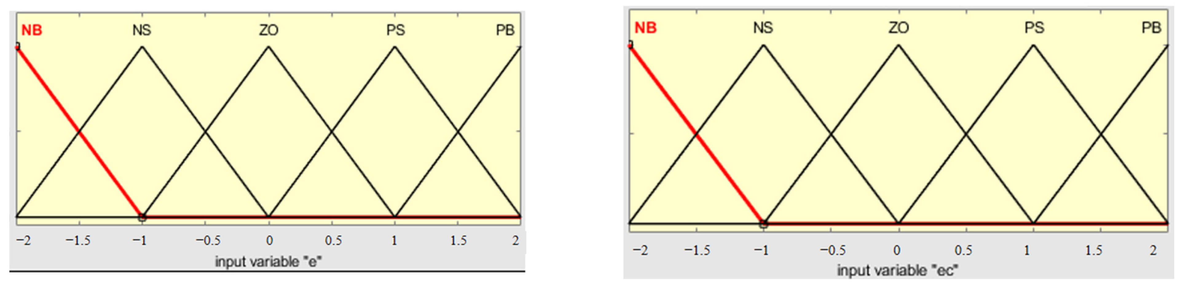
In the design of the fuzzy controller, the quantization range for the error e and the error rate ec is set within [−2,2], and this continuous interval is discretized to obtain a discrete set [42,43]. The input linguistic variables include e and ec, while the output variables are the PID parameter adjustment quantities ΔKp, ΔKi, and ΔKd. Their basic universes of discourse and quantized domains are shown in Table 4 [44,45].
(2)
This design adopts triangular membership functions. By adjusting the parameters of the triangular membership functions, different input quantities can be precisely classified into corresponding fuzzy subsets. The triangular function is widely used in engineering applications. The shape of the membership functions is shown in the corresponding Figure 10.
(3)
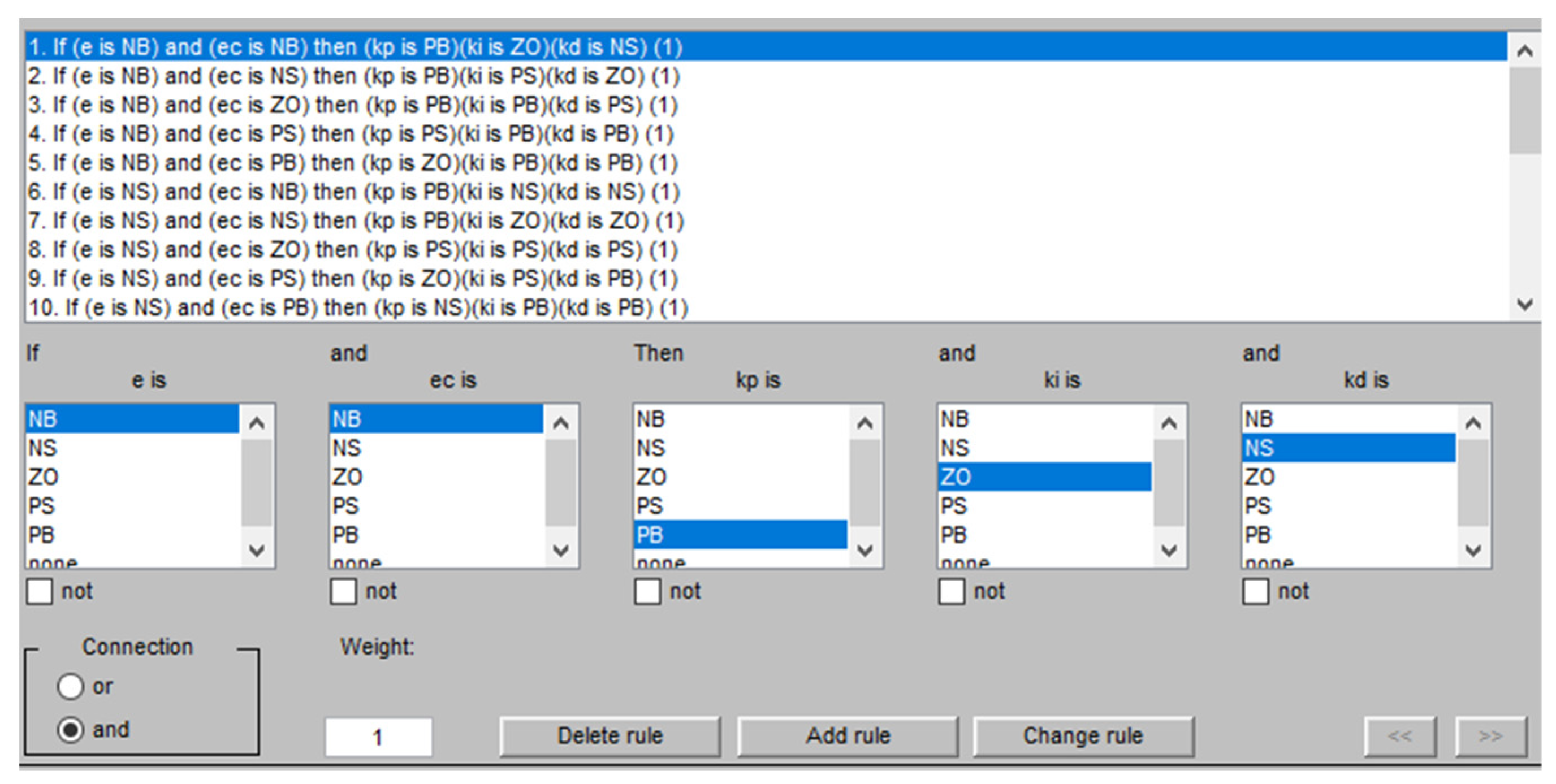
This study adopts the Mamdani-type fuzzy inference system and constructs a fuzzy controller with two inputs and one output. The input variables are sowing depth error e and error rate ec, and the output variable U corresponds to the online adjustment increments of the PID controller parameters. All three variables are divided into seven membership subsets: NB (negative big), NM (negative medium), NS (negative small), ZO (zero), PS (positive small), PM (positive medium), and PB (positive big). During each control cycle, the system continuously acquires real-time error e and error rate ec, and based on the pre-defined rule base in the form of “IF e is A AND ec is B THEN U is C”; fuzzy inference is applied to generate the corresponding control adjustment output. Although the rules are summarized from observations and empirical experience of sowing depth control effects, their core still follows the classic PID tuning principles, with modifications based on actual control needs.
The design of fuzzy control rules follows these principles:
In the case of large errors, to shorten the response time and quickly suppress the deviation, a large value for the proportional increment ΔKp should be selected, and the differential increment ΔKd should be reduced in order to avoid strong oscillation and derivative saturation. If necessary, the integral increment ΔKi can be set to zero to reduce initial overshoot.
For moderate errors, ΔKp should be moderately reduced to suppress overshoot, while keeping ΔKi and ΔKd at medium levels to maintain system stability without excessive oscillation.
When the error is small, increasing both ΔKp and ΔKi helps reduce steady-state error. Meanwhile, ΔKd should be negatively correlated with the error rate ec to enhance suppression of small disturbances and prevent rapid oscillations of control output around the target.
Based on the above principles and combined with the sensitivity analysis of Kp, Ki, and Kd, a set of fuzzy rule tables (examples shown in Table 5, Table 6 and Table 7) applicable to online sowing depth control is established, providing reliable support for system operation under complex and varying terrain conditions.
Using the fuzzy rule editor, a total of 25 designed rules were implemented into the system, as illustrated in Figure 11.
(4)
In the sowing depth PID controller, the parameter self-tuning formulas are given as follows:
K p = K p 0 + Δ K p K i = K i 0 + Δ K i K d = K d 0 + Δ K d

3. Results and Discussion

This chapter presents the construction of a sowing depth control system simulation model based on the MATLAB (MathWorks, R2020b, U.S.)/Simulink platform, aimed at verifying the performance of the fuzzy PID control strategy under various terrain conditions [46]. By comparing it with a traditional PID control strategy, the response speed and steady-state error of the control system are analyzed to evaluate the applicability and superiority of the fuzzy control method in sowing depth regulation [47].

3.1. MATLAB/Simulink Simulation and System Verification

3.1.1. Simulation Model Construction and Parameter Settings

In this section, a Simulink simulation model of the sowing depth control system is developed. Each module is carefully designed and parametrized to ensure the engineering feasibility of the simulation results. The model is based on the sowing machine dynamics transfer function established earlier, incorporating the actual characteristics of the stepper motor and data from the bench test platform. A complete control system simulation platform is constructed, as shown in Figure 12 [48].
The simulation system primarily includes the following modules:
(1)
Reference Input Module: This defines the target value of the sowing depth to simulate the actual sowing depth setpoint.
(2)
Disturbance Module: This uses a combination of constant and sine wave signals to simulate different terrain conditions, such as flat ground, gentle slopes, and wavy undulations.
(3)
Error Calculation Module: This calculates the real-time error e between the setpoint and detected sowing depth and computes the error rate ec using a difference method.
(4)
Controller Module:
Traditional PID Controller: This uses fixed parameters Kp, Ki, and Kd for control.
Fuzzy PID Controller: This inputs error e and error rate ec into the fuzzy controller to generate PID parameter adjustments, enabling online updating of PID values for adaptive control.
(5)
Controlled Object Module: The model of depth-limiting wheel height variation is represented using a transfer function or state-space form, reflecting the dynamic characteristics of the sowing machine.
(6)
Output Module: This captures simulation outputs such as sowing depth response curves and error curves for evaluating system performance [49].
The simulation parameters are set as follows: the simulation step size is Ts = 0.01 s, and the total simulation time is 10 s. In the fuzzy PID controller, the initial PID parameters are set as Kp0 = 60, Ki0 = 2, and Kd0 = 0.1. Triangular membership functions are used. The universes of discourse for input variables e and ec are set to [−2, 2], consistent with the normalized terrain error range. For detailed fuzzy control rules, refer to Section 2.2.4 [50].

3.1.2. Simulation Testing Under Different Terrain Conditions

The simulation considers three typical terrain scenarios.
Scenario 1: Flat Ground
No disturbance is applied; this scenario is used to evaluate the steady-state performance and response time of the control system. Both controllers can follow the target depth, but the fuzzy PID controller converges faster and exhibits slightly lower steady-state error.
Scenario 2: Gentle Slope
The input is a slowly increasing/decreasing slope signal, simulating a long gentle terrain slope. In this case, the traditional PID controller shows a noticeable lag and minor overshoot during adjustment. In contrast, the fuzzy PID controller dynamically adjusts its parameters based on the changing error, effectively suppressing overshoot and quickly converging to the target sowing depth.
Scenario 3: Periodic Undulation
A sine wave input simulates terrain with periodic undulations (such as unevenly tilled fields). The traditional PID controller struggles to respond to the varying error, resulting in a significant performance decline. On the other hand, the fuzzy PID controller continuously and adaptively adjusts its control parameters, significantly reducing sowing depth fluctuations and showing superior adaptability.

3.1.3. Comparative Analysis of Simulation Results

The simulation performance of the traditional PID and fuzzy PID control strategies was compared under three typical terrain disturbance scenarios. Key evaluation indicators include system rise time, overshoot, settling time, and disturbance rejection capability. Table 8 summarizes the quantitative comparison of the two control strategies under the gentle slope disturbance scenario.
As shown in the table, the fuzzy PID controller outperforms the traditional PID controller across several key performance metrics. Specifically, the rise time is reduced from 0.290 s to 0.262 s, representing an approximate 9.7% improvement in response speed. The system overshoot decreases from 44.7% to 32.3%, a reduction of 27.7%, effectively mitigating the overshoot problem. Moreover, the settling time drops from 3.119 s to 1.652 s, a decrease of nearly 47.0%, indicating that the system reaches a steady state more quickly.
Additionally, under the same disturbance intensity, the fuzzy PID controller demonstrates stronger disturbance rejection. As shown in the simulation response curves (Figure 13), when a sudden slope disturbance occurs, the output of the traditional PID controller exhibits significant oscillations. In contrast, the fuzzy PID controller maintains a smaller oscillation amplitude and quickly stabilizes after the disturbance ends, resulting in a significantly narrower error band.
In summary, the simulation results clearly demonstrate that the fuzzy control strategy, which performs online adjustment of PID parameters, not only improves the system’s fast response to step changes but also exhibits superior stability and robustness when encountering terrain undulations and other external disturbances. These findings provide a solid foundation for subsequent physical tests and practical field applications.

3.2. Construction Verification of the Test Platform and Data Analysis

3.2.1. Experimental Platform Overview
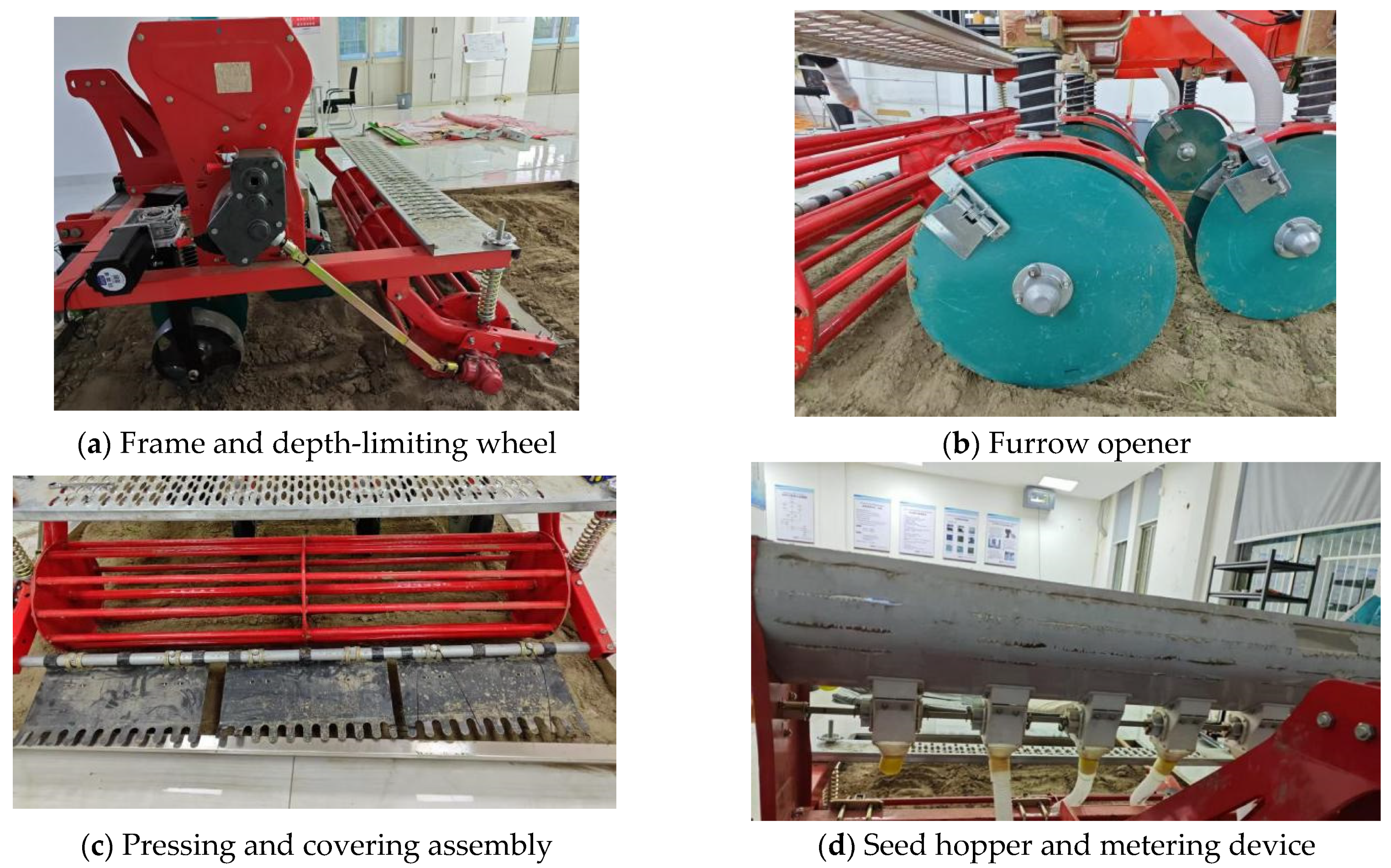
To evaluate the control performance of the proposed fuzzy PID-based sowing depth adjustment system under practical conditions, an indoor bench test platform was constructed (see Figure 14 and Figure 15). This platform enables validation of the system’s response and sowing depth regulation performance under various terrain conditions, with key data collected for statistical analysis. The test platform comprises the following components:
(1)
Multi-Row Sowing Machine Body:
The core of the platform is a multi-row wheat strip-sowing machine. The frame supports the entire machine, the furrow opener cuts grooves in the soil bed, and the depth-limiting wheel closely follows the soil surface to precisely regulate sowing depth. This configuration mimics actual sowing operations and ensures that the seeding mechanism operates at the preset depth.
(2)
Replaceable Terrain Soil Trough:
The soil trough is constructed from welded steel plates with dimensions of 3000 mm × 2000 mm × 100 mm, capable of holding approximately 0.6 m3 of soil. By installing interchangeable modules at the base, it can simulate three types of terrain—flat, convex, and concave—accurately reproducing the effects of field terrain variations on sowing depth [51].
(3)
Horizontal Drive Unit:
The lateral movement of the platform is achieved using a KGX2000 (Dongtai Su Kai Trading Co., Ltd., Dongtai, China) double-rail, four-slider ball screw slide module. Equipped with high-precision ball screws and linear guides, this unit delivers a horizontal thrust of up to 200 kg. Its stable and wear-resistant operation ensures consistent performance during extended test cycles.
(4)
Connection Structure Between Frame and Slide:
To maintain both rigidity and flexibility between the sowing machine and the slide, a custom connector was designed. One end is welded to the slide’s fixed plate, while the other end connects to the sowing frame via a universal floating joint. This design effectively absorbs vertical and torsional vibrations, preventing excessive loads on the screw guide, thereby improving overall system stability and measurement accuracy.
(5)
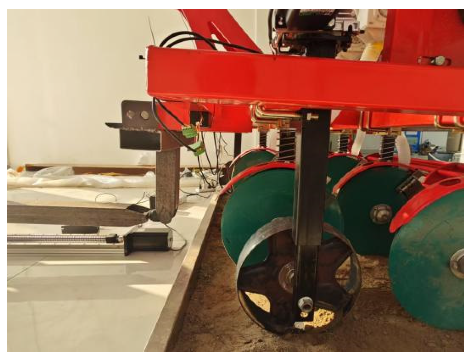
Depth-Limiting Adjustment Module:
A stepper motor-driven depth-limiting wheel mechanism provides real-time sowing depth adjustment [52].
(6)
Sensor System:
A laser range sensor captures sowing depth measurements, while an array-based LiDAR sensor acquires terrain undulation data for data fusion.
(7)
Control System:
The upper computer executes the fuzzy PID control algorithm in MATLAB/Simulink, while the lower controller collects sensor data and drives the actuators.

3.2.2. Experimental Plan and Terrain Conditions

To replicate the various terrain disturbances encountered in actual field operations and scientifically evaluate system performance, three typical working conditions were designed: flat terrain, gentle slope, and localized undulation (see Figure 16).
(1)
Flat terrain: The test bed surface is kept level to verify the system’s steady-state response and sowing depth control accuracy in the absence of external disturbances.
(2)
Gentle slope: A linear inclined surface is set on one side of the platform to simulate a gradual ascent or descent, assessing the controller’s ability to track continuous slope changes during operation.
(3)
Localized undulation: Uneven terrain modules of varying height are randomly placed on the platform to simulate irregular soil clumps or straw residue, testing the system’s response to sudden terrain disturbances.
For each terrain condition, comparative experiments were conducted using both traditional PID and fuzzy PID control strategies. Target sowing depth, actual depth, and error variation were recorded and statistically analyzed. Meanwhile, the system’s response speed and adjustment stability were observed.
During the experiment, a vernier caliper was used to manually measure the actual sowing depth after each test run. These measurements were then compared with system-detected values to calculate absolute error. In addition, key performance indicators such as response time, overshoot, and steady-state error were extracted for comparison. The manual measurement procedure is illustrated in Figure 17.

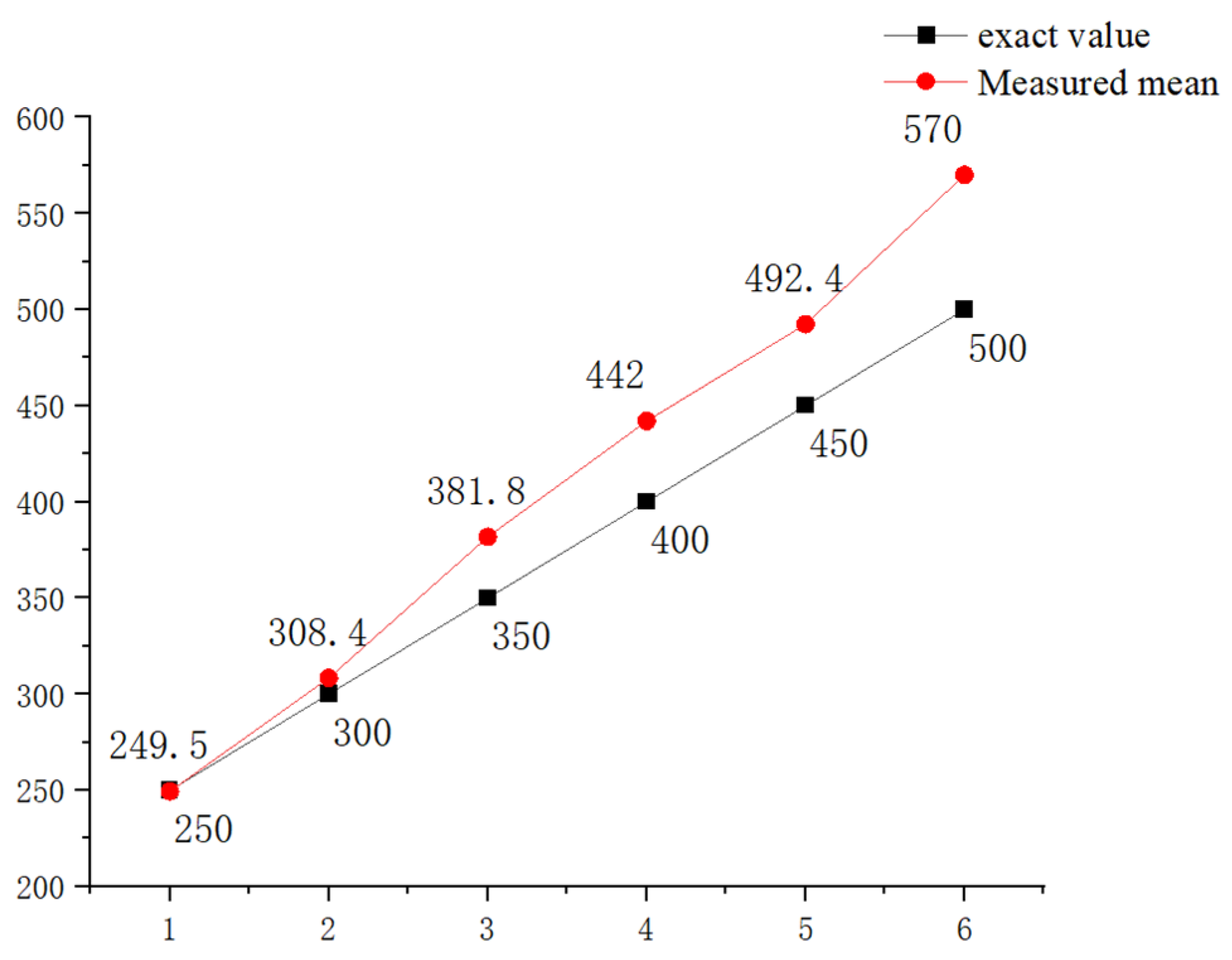
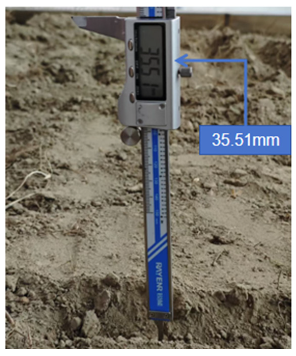
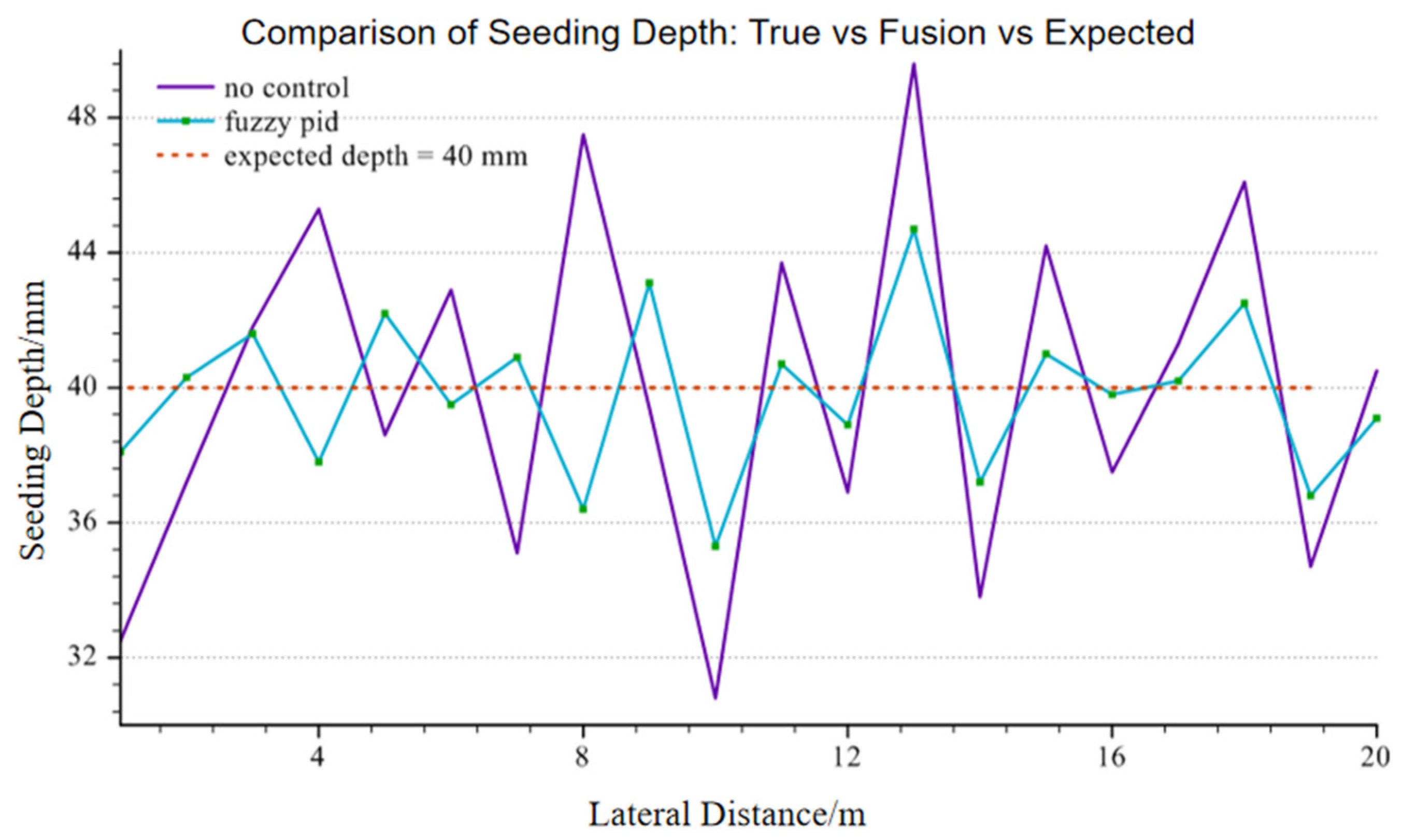
3.2.3. Data Acquisition and Analysis

To comprehensively evaluate the sowing depth adjustment performance of the designed fuzzy PID controller under different terrain conditions, a series of comparative experiments were carried out on the indoor bench test platform for three typical working conditions: flat terrain, gentle slope terrain, and undulating terrain. Each experiment was conducted with a target sowing depth of 40 mm, and the fuzzy PID control strategy was executed automatically by the host computer to drive the stepper motor in adjusting the position of the depth-limiting wheel. Meanwhile, at the same positions, the actual sowing depth was manually measured using a vernier caliper, and the true depth value after each sowing action by the depth-limiting wheel was recorded.
To enhance the statistical representativeness of the results, 30 consecutive sowing depth measurements were conducted under each working condition. The actual sowing depth values were obtained using a caliper, and the absolute error between these values and the target value was calculated. The error data under the conditions of “no control strategy” and “fuzzy PID control strategy” were statistically analyzed, and the average error and standard deviation were calculated. An independent-sample t-test was further conducted to analyze whether there was a significant difference in the error distribution between the two control strategies. Table 9 presents the error statistics and t-test results of the two control methods under various terrain conditions.
Figure 18 shows the experimental comparison curves of actual seeding depth measurements under gentle slope terrain, which visually demonstrates the differences in actual seeding depth error between the fuzzy PID control and the traditional no-control strategy. From the trend of the curve response, the fuzzy PID control shows a shorter response time and smaller overshoot in the slope variation area and can quickly return to the target seeding depth level, demonstrating excellent slope-adaptive ability.
As shown in Table 9, under all test conditions, the fuzzy PID control significantly reduced the average error and fluctuation range of the sowing depth, and the p-values were all less than 0.05, indicating statistical significance. In flat terrain, the average error decreased from 5.03 mm to 4.49 mm, with an error reduction of approximately 10.7%, and the standard deviation decreased by about 33.4%. On gentle slopes, the average error decreased from 6.81 mm to 5.25 mm, with an error reduction of approximately 22.9%, demonstrating a good response ability to continuous slope disturbances. In undulating terrain, the fuzzy PID control reduced the average error from 7.11 mm to 6.43 mm, which is a reduction of about 9.6%; although the control challenge was greater, it still outperformed the no-control situation significantly.
In summary, the fuzzy PID control strategy based on multi-sensor fusion demonstrated superior sowing depth control performance under flat, gentle slope, and undulating terrain conditions, not only significantly reducing the average error but also causing the error fluctuation range to converge. This provides strong data support and technical assurance for accurate sowing operations under actual field conditions.

3.3. Discussion

This study conducted in-depth experimental verification of a sowing depth adjustment system on an indoor bench test platform, focusing on the actual application performance of multi-sensor fusion and a fuzzy PID control algorithm under different terrain disturbance conditions. By constructing three typical terrain scenarios (flat, gentle slope, and undulating) and performing comparative tests using traditional PID and fuzzy PID control strategies, respectively, key indicators such as control error, response speed, and anti-disturbance capability were systematically evaluated, further verifying the stability and practicality of the proposed system in complex environments. However, the current research only simulated typical slopes and local undulating terrain and has not covered the overall picture under different operating speeds and other conditions. To address this issue, we will introduce a variable-speed drive scheme in our subsequent research and conduct a more comprehensive robustness assessment based on the simulation path model to verify the system’s adaptability under multiple speeds or more complex paths.
From the experimental results, the introduction of fuzzy PID control significantly improved the overall performance of the sowing depth control system. In all test conditions, both the average sowing depth error and the standard deviation were reduced compared with traditional PID. Particularly under gently sloping and undulating terrain, the fuzzy controller demonstrated superior terrain adaptability and disturbance compensation performance. This result indicates that fuzzy PID, by introducing a joint rule adjustment mechanism based on error and error rate, effectively modeled and controlled nonlinear dynamic conditions, enabling the system to exhibit smaller steady-state error, shorter settling time, and weaker overshoot under discontinuous terrain variations. From the perspective of innovation, this study is the first to integrate the real-time depth detection values of the laser sensor with the terrain correction values provided by the area array sensor, thereby forming a more accurate estimation of the depth error. Additionally, through the online tuning of PID gains using fuzzy PID, the adaptive adjustment of the overall depth of the machine is accomplished.
Furthermore, from the error distribution curves and box plot statistics, it was observed that the sowing depth output under fuzzy PID control was more centralized with narrower error fluctuation range, indicating good repeatability and consistency. This shows that the controller has strong robustness and adaptability; even under frequent complex terrain disturbances, it can still effectively track the target sowing depth. In addition, compared to the traditional fixed-parameter PID scheme, the fuzzy controller responded faster and adjusted more smoothly when facing abrupt terrain changes, fully reflecting the advantage of flexible adjustment in control logic.
Apart from the effectiveness of the control strategy itself, the structural configuration and modular integration of the test platform also played a critical supporting role in the overall system performance. Through high-precision soil troughs to simulate diverse terrains, modular assembly of the sowing mechanism and the depth-limiting wheel system, and deployment of high-frequency response data acquisition units, a large amount of verifiable data was provided for the accuracy analysis of the sowing depth adjustment strategy. The platform’s stability and systematic integration also laid the technical foundation for future large-scale field testing.
In summary, the proposed sowing depth adjustment system demonstrated excellent comprehensive performance in hardware structural design, sensor fusion scheme, and control strategy implementation. The introduction of fuzzy PID effectively compensated for the response lag and insufficient control accuracy of traditional PID in nonlinear disturbance scenarios, showing strong engineering applicability and potential for wider adoption.

4. Conclusions

(1)
Multi-Sensor Fusion Model Construction
This system integrates the P8864-SMD-B15 array-based LiDAR sensor and the STP-23L laser range sensor to obtain terrain profile information and the actual height between the depth-limiting mechanism and the soil surface, respectively. Through weighted averaging and an error feedback-based fusion algorithm, dynamic correction of sowing depth estimation is achieved. Compared to single-sensor approaches, this method significantly improves the stability and anti-interference capability of sowing depth estimation under complex terrain conditions.
(2)
Fuzzy PID-Based Online Adjustment Control Strategy Design
A fuzzy PID controller was constructed with sowing depth error and its rate of change as inputs. Reasonable membership functions and “expert experience” rule bases were set to realize dynamic online adjustment of PID parameters. Simulation and physical experiment results show that this control strategy outperforms traditional fixed-parameter PID controllers in terms of response time, overshoot, and steady-state error, effectively improving key indicators and exhibiting good adaptability and robustness.
(3)
Dual-Level Experimental Verification Platform Establishment and Application
This study developed a simulation model of control logic on MATLAB/Simulink and designed a modular indoor bench test platform capable of terrain adjustment, closed-loop feedback, sensor fusion, and actuator control. Through continuous sowing depth measurements and comparative validations under three typical working conditions, the system’s adjustment capability and consistency were thoroughly evaluated, providing reliable data support and technical reference for future field experiments and engineering integration.
(4)
Future Research and Engineering Expansion
Although the system demonstrates high control accuracy under laboratory conditions, actual field operations may still encounter more complex interference factors, such as variations in soil moisture, fluctuations in operating speed, mechanical vibrations, and potential sensor occlusions. Future research can be extended in the following directions: (i) incorporating a deep learning-based self-calibration mechanism within the multi-sensor fusion framework to improve the adaptability of the error model; (ii) carrying out field validation in large-scale farmland scenarios to develop a high-reliability sowing depth control system; and (iii) investigating the integration of sowing depth regulation with variable-rate fertilization and intelligent navigation, thereby advancing the intelligent evolution of agricultural machinery and enabling the broader implementation of precision agriculture.

Author Contributions

Conceptualization, B.Q. and E.B.; methodology, Z.T., Y.L. (Yi Lian), M.S. and Y.L. (Yueyue Li); validation, Z.T., Y.L. (Yi Lian), M.S. and Y.L. (Yueyue Li); formal analysis, Y.L. (Yueyue Li); data curation, Y.L. (Yi Lian) and Y.L. (Yueyue Li); investigation, Y.L. (Yueyue Li); writing—original draft preparation, Y.L. (Yueyue Li); writing—review and editing, Z.T., E.B. and Y.L. (Yi Lian); supervision, Z.T. All authors have read and agreed to the published version of the manuscript.

Funding

This study was funded by an open project from the Key Laboratory of Modern Agricultural Equipment, Ministry of Agriculture and Rural Affairs, project number: 2023001.

Data Availability Statement

The data used to support the findings of this study are available from the corresponding author upon request.

Conflicts of Interest

The authors declare no conflicts of interest.

References

  1. Nielsen, S.K.; Munkholm, L.J.; Lamande, M.; Norremark, M.; Skou-Nielsen, N.; Edwards, G.T.C.; Green, O. Seed Drill Instrumentation for Spatial Coulter Depth Measurements. Comput. Electron. Agric. 2017, 141, 207–214. [Google Scholar] [CrossRef]
  2. Romaneckas, K.; Steponavicius, D.; Jasinskas, A.; Kazlauskas, M.; Naujokiene, V.; Bruciene, I.; Svereikaite, A.; Sarauskis, E. How to Analyze, Detect and Adjust Variable Seedbed Depth in Site-Specific Sowing Systems: A Case Study. Agronomy 2022, 12, 1092. [Google Scholar] [CrossRef]
  3. Studhalter, M.; Janovicek, K.; Kim, J.; Byker, H.; Mountain, N.; Nasielski, J. Row Spacing, Seeding Depth, Seeding Rate, and Trinexapac-Ethyl Effects on Oat Yield and Lodging. Crop Sci. 2023, 63, 2509–2523. [Google Scholar] [CrossRef]
  4. Kong, L.; Sun, M.; Wang, F. Effects of Seeding Depth on Subcrown Internode Elongation and Grain Yield in Wheat. Pakistan J. Agric. Sci. 2016, 53, 625–632. [Google Scholar]
  5. Wang, Q.; Xu, Q.; Lu, C.; Li, H.; He, J.; Wang, Q. Research Status and Development of Key Technologies for No-Tillage Seeding Intellectualization. J. S. China Agric. Univ. 2021, 42, 27–35. [Google Scholar]
  6. Bai, H.; Fang, X.; Wang, D.; Yuan, Y.; Zhou, L.; Niu, K. Design and Test of Control System for Seeding Depth and Compaction of Corn Precision Planter. Trans. Chin. Soc. Agric. Mach. 2020, 51, 61–72. [Google Scholar]
  7. Mapoka, K.O.M.; Birrell, S.J.; Tekeste, M. A Comprehensive Survey of Nondestructive Sensing Technologies for the Detection of Corn Seeds in a Closed Trench and Measuring Planting Depth to Augment the Conventional Method. Comput. Electron. Agric. 2019, 158, 249–257. [Google Scholar] [CrossRef]
  8. Lee, J.; Yamazaki, M.; Oida, O.; Nakashima, H.; Shimizu, H. Electro-Hydraulic Tillage Depth Control System for Rotary Implements Mounted on Agricultural Tractor Design and Response Experiments of Control System. Terramechanics 1998, 35, 229–238. [Google Scholar] [CrossRef]
  9. Suomi, P.; Oksanen, T. Automatic Working Depth Control for Seed Drill Using Iso 11783 Remote Control Messages. Comput. Electron. Agric. 2015, 116, 30–35. [Google Scholar] [CrossRef]
  10. Nielsen, S.K.; Nørremark, M.; Green, O. Sensor and Control for Consistent Seed Drill Coulter Depth. Comput. Electron. Agric. 2016, 127, 690–698. [Google Scholar] [CrossRef]
  11. Zhao, J.L.; Zhu, L.T.; Jia, H.L.; Huang, D.Y.; Guo, M.Z.; Cong, Y.J. Automatic Depth Control System for a No-Till Seeder. Int. J. Agric. Biol. Eng. 2018, 11, 115–121. [Google Scholar] [CrossRef]
  12. Morales, Y.; Tsubouchi, T.; Yuta, S. Vehicle Localization in Outdoor Mountainous Forested Paths and Extension of Two-Dimensional Road Centerline Maps to Three-Dimensional Maps. Adv. Robot. 2010, 24, 489–513. [Google Scholar] [CrossRef]
  13. Zhang, S. Application of Fuzzy Pid Control in Motor Test. In Proceedings of the 2nd International Conference on Computer Engineering, Information Science and Application Technology (Iccia), Wuhan, China, 8–9 July 2017. [Google Scholar]
  14. Phu Nguyen, D.; Hung Nguyen, N.; Ahmadian, A.; Senu, N. A New Fuzzy Pid Control System Based on Fuzzy Pid Controller and Fuzzy Control Process. Int. J. Fuzzy Syst. 2020, 22, 2163–2187. [Google Scholar]
  15. Ma, F. An Improved Fuzzy Pid Control Algorithm Applied in Liquid Mixing System. In Proceedings of the IEEE International Conference on Information and Automation (Icia), Hailar, China, 28–30 July 2014. [Google Scholar]
  16. Simon, J. Fuzzy Control of Self-Balancing, Two-Wheel-Driven, SLAM-Based, Unmanned System for Agriculture 4.0 Applications. Machines 2023, 11, 467. [Google Scholar] [CrossRef]
  17. Wrat, G.; Bhola, M.; Ranjan, P.; Mishra, S.K.; Das, J. Energy saving and Fuzzy-PID position control of electro-hydraulic system by leakage compensation through proportional flow control valve. ISA Trans. 2020, 101, 269–280. [Google Scholar] [CrossRef]
  18. Liu, W.; Ma, B.; Chen, X.; Yu, C.; Jing, T.; Huang, L. Design of a Single Sowing Depth Measurement System for an Air Suction Corn Planter. Eng. Agric. 2022, 42, e20210173. [Google Scholar]
  19. Valente, M.; Joly, C.; De La Fortelle, A. Deep Sensor Fusion for Real-Time Odometry Estimation. In Proceedings of the 2019 Ieee/Rsj International Conference on Intelligent Robots and Systems (Iros), Macau, China, 3–8 November 2019; pp. 6679–6685. [Google Scholar]
  20. Zhao, S.; Zhang, Y. Design and Field Test of Corn Seeding System Base on Fuzzy Pid Control Method Combine with Pso. Eng. Agric. 2024, 44, e20230123. [Google Scholar] [CrossRef]
  21. Liu, W.; Ma, B.; Ma, L.; Chen, X.; Yu, C.; Huang, L.; Li, H. Application of Kalman Filter Combined with Genetic Pid Control Algorithm in Improving Seeding Accuracy. J. Anhui Agric. Univ. 2021, 48, 674–679. [Google Scholar]
  22. Liu, C.; Zhao, J.; Gu, J.; Du, Y.; Li, Z.; Zhu, Z.; Mao, E. Pressure Control Algorithm Based on Adaptive Fuzzy Pid with Compensation Correction for the Tractor Electronic Hydraulic Hitch. Appl. Sci. 2020, 10, e20230123. [Google Scholar] [CrossRef]
  23. Tang, B.Y.; Da, X.L.; Wang, W.J. An Adaptive Control Method for Time-Varying Systems. Eur. J. Oper. Res. 2000, 124, 342–352. [Google Scholar] [CrossRef]
  24. Chen, J.; Ning, X.; Li, Y.; Yang, G.; Wu, P.; Chen, S. A Fuzzy Control Strategy for the Forward Speed of a Combine Harvester Based on Kdd. Appl. Eng. Agric. 2017, 33, 15–22. [Google Scholar]
  25. Liu, H.; Yan, S.; Shen, Y.; Li, C.; Zhang, Y.; Hussain, F. Model Predictive Control System Based on Direct Yaw Moment Control for 4Wid Self-Steering Agriculture Vehicle. Int. J. Agric. Biol. Eng. 2021, 14, 175–181. [Google Scholar] [CrossRef]
  26. Song, X.; Li, H.; Chen, C.; Xia, H.; Zhang, Z.; Tang, P. Design and Experimental Testing of a Control System for a Solid-Fertilizer-Dissolving Device Based on Fuzzy Pid. Agriculture 2022, 12, 1382. [Google Scholar] [CrossRef]
  27. Ahmad, F.; Adeel, M.; Qiu, B.; Ma, J.; Shoaib, M.; Shakoor, A.; Chandio, F.A. Sowing Uniformity of Bed-Type Pneumatic Maize Planter at Various Seedbed Preparation Levels and Machine Travel Speeds. Int. J. Agric. Biol. Eng. 2021, 14, 165–171. [Google Scholar] [CrossRef]
  28. Yan, T.; Zhu, H.; Sun, L.; Wang, X.; Ling, P. Investigation of an Experimental Laser Sensor-Guided Spray Control System for Greenhouse Variable-Rate Applications. Trans. Asabe 2019, 62, 899–911. [Google Scholar] [CrossRef]
  29. Zhu, X.; Chikangaise, P.; Shi, W.; Chen, W.-H.; Yuan, S. Review of Intelligent Sprinkler Irrigation Technologies for Remote Autonomous System. Int. J. Agric. Biol. Eng. 2018, 11, 23–30. [Google Scholar] [CrossRef]
  30. Li, Y.; Qi, B.; Bao, E.; Tang, Z.; Lian, Y.; Sun, M. Design and Analysis of Sowing Depth Detection and Control Device for Multi-Row Wheat Seeders Adapted to Different Terrain Variations. Agriculture 2025, 15, 290. [Google Scholar] [CrossRef]
  31. Chen, J.; Zhang, Z.; Li, Y.; Guan, Z.; Tang, X. Research on Following Suction and Discharging Motion Control Method of Vacuum-Vibration Precision Seeding Manipulator. Appl. Eng. Agric. 2022, 38, 873–883. [Google Scholar] [CrossRef]
  32. Hu, J.; Zhao, X.; Liu, W.; Yao, M.; Zhao, J. Development of a Seeding Control Method Based on Seed Height in the Hopper of a Precision Wheat Drill. Appl. Eng. Agric. 2021, 37, 1131–1138. [Google Scholar] [CrossRef]
  33. Yang, S.; Zhai, C.; Gao, Y.; Dou, H.; Zhao, X.; He, Y.; Wang, X. Planting Uniformity Performance of Motor-Driven Maize Precision Seeding Systems. Int. J. Agric. Biol. Eng. 2022, 15, 101–108. [Google Scholar] [CrossRef]
  34. Cheema, M.J.M.; Nauman, M.; Ghafoor, A.; Farooque, A.A.; Haydar, Z.; Ashraf, M.U.; Awais, M. Direct Seeding of Basmati Rice Through Improved Drills: Potential and Constraints in Pakistani Farm Settings. Appl. Eng. Agric. 2021, 37, 53–63. [Google Scholar] [CrossRef]
  35. Zhang, Z.; Chen, C.; Li, H.; Xia, H. Design and Evaluation of a Control System for the Fertigation Device. J. Asabe 2022, 65, 1293–1302. [Google Scholar] [CrossRef]
  36. Huang, X.-Y.; Pan, S.-H.; Sun, Z.-Y.; Ye, W.-T.; Aheto, J.H. Evaluating Quality of tomato During Storage Using Fusion Information of Computer Vision and Electronic Nose. J. Food Process Eng. 2018, 41, e12832. [Google Scholar] [CrossRef]
  37. Khulal, U.; Zhao, J.; Hu, W.; Chen, Q. Nondestructive Quantifying total Volatile Basic Nitrogen (Tvb-N) Content in Chicken Using Hyperspectral Imaging (Hsi) Technique Combined with Different Data Dimension Reduction Algorithms. Food Chem. 2016, 197, 1191–1199. [Google Scholar] [CrossRef]
  38. Huang, X.; Wang, W.; Li, Z.; Wang, Q.; Zhu, C.; Chen, L. Design Method and Experiment of Machinery for Combination of Seed Fertilizer and Herbicide. Int. J. Agric. Biol. Eng. 2019, 12, 63–71. [Google Scholar]
  39. Yao, K.; Sun, J.; Tang, N.; Xu, M.; Cao, Y.; Fu, L.; Zhou, X.; Wu, X. Nondestructive Detection for Panax Notoginseng Powder Grades Based on Hyperspectral Imaging Technology Combined with Cars-Pca and Mpa-Lssvm. J. Food Process Eng. 2021, 44, e13718. [Google Scholar] [CrossRef]
  40. Zhang, T.; Wu, X.; Wu, B.; Dai, C.; Fu, H. Rapid Authentication of the Geographical Origin of Milk Using Portable Near-Infrared Spectrometer and Fuzzy Uncorrelated Discriminant Transformation. J. Food Process Eng. 2022, 45, e1404. [Google Scholar] [CrossRef]
  41. Li, Y.; Cao, Q.; Liu, F. Research on Fuzzy Pid Control of Electronically Controlled Hydraulic Power Steering System for Unmanned Agricultural Vehicle. In Proceedings of the International Conference on High Performance Big Data and Intelligent Systems (Hpbd&Is), Shenzhen, China, 9–11 May 2019. [Google Scholar]
  42. Li, M.; Wang, L.; Liu, J.; Ye, J. Method Study on Fuzzy-Pid Adaptive Control of Electric-Hydraulic Hitch System. In Proceedings of the International Conference on Advances In Materials, Machinery, Electronics (Amme), Wuhan, China, 25–26 February 2017. [Google Scholar]
  43. Wang, Q.; Zhou, J.; Hou, J. Irrigation and Fertilizer Control Strategy Based on Variable Domain Fuzzy Pid. J. Northwest A F Univ. Nat. Sci. Ed. 2023, 51, 144–154. [Google Scholar]
  44. Wang, Y.; Liu, J.; Li, J.; Chen, B.; Li, Q. Using the Smith Pso-Fuzzy Pid Model to Control Electrical Conductivity of Nutrient Solution of Precision Fertilization. J. Irrig. Drain. 2022, 41, 37–44. [Google Scholar]
  45. Xue, J.; Zhou, L. Design of Fuzzy Pid Control Algorithm Facing to Greenhouse. In Proceedings of the 9th International Conference on Intelligent Human-Machine Systems and Cybernetics (Ihmsc), Hangzhou, China, 26–27 August 2017. [Google Scholar]
  46. Yu, Y.; Hao, S.; Guo, S.; Tang, Z.; Chen, S. Motor torque Distribution Strategy for Different Tillage Modes of Agricultural Electric Tractors. Agriculture 2022, 12, 1373. [Google Scholar] [CrossRef]
  47. Tang, Z.; Wang, H.; Jing, T.; Liu, S.; Shen, C. Centroid Swinging Property of a Machine Body Undergoing Longitudinal Excitation in a Straw Compression Baler. Eng. Agric. 2024, 44, e20230109. [Google Scholar] [CrossRef]
  48. Chen, S.; Qi, J.; Gao, J.; Chen, W.; Fei, J.; Meng, H.; Ma, Z. Research on the Control System for the Conveying and Separation Experimental Platform of Tiger Nut Harvester Based on Sensing Technology and Control Algorithms. Agriculture 2025, 15, 115. [Google Scholar] [CrossRef]
  49. Wang, R.; Zhang, K.; Ding, R.; Jiang, Y.; Jiang, Y. A Novel Hydraulic Interconnection Design and Sliding Mode Synchronization Control of Leveling System for Crawler Work Machine. Agriculture 2025, 15, 137. [Google Scholar] [CrossRef]
  50. Zhang, Y.; Wei, Z.; Lin, Q.; Zhang, L.; Xu, J. Mbd of Grey Prediction Fuzzy-Pid Irrigation Control Technology. Desalination Water Treat. 2018, 110, 328–336. [Google Scholar] [CrossRef]
  51. Liu, L.; Wang, X.; Zhang, X.; Cheng, X.; Wei, Z.; Ji, J.; Li, H.; Zhang, H.; Wang, M. Sowing Depth Control Strategy Based on the Downforce Measurement and Control System of ’T’-Shaped Furrow Opener. Biosyst. Eng. 2024, 247, 97–108. [Google Scholar] [CrossRef]
  52. Zhai, J.; Xia, J.; Zhou, Y.; Zhang, S. Design and Experimental Study of the Control System for Precision Seed-Metering Device. Int. J. Agric. Biol. Eng. 2014, 7, 13–18. [Google Scholar]
Figure 1. Schematic diagram of sowing depth detection.
Agronomy 15 01490 g001
Figure 2. Schematic diagram of basic PID control.
Agronomy 15 01490 g002
Figure 3. Terrain data acquisition using an array-based LiDAR sensor.
Agronomy 15 01490 g003
Figure 4. Three-dimensional structural view of a laser range sensor.
Agronomy 15 01490 g004
Figure 5. Comparison of the measurement data of the array sensor with accurate values.
Agronomy 15 01490 g005
Figure 6. Components of the depth control mechanism.
Agronomy 15 01490 g006
Figure 7. Physical structure of the multi-row wheat sowing machine.
Agronomy 15 01490 g007
Figure 8. Simplified diagram of the mathematical model of the depth adjustment system.
Agronomy 15 01490 g008
Figure 9. Host computer interface for data acquisition and processing.
Agronomy 15 01490 g009
Figure 10. Membership functions of e and ec.
Agronomy 15 01490 g010
Figure 11. Fuzzy rule statements.
Agronomy 15 01490 g011
Figure 12. Simulink simulation system diagram.
Agronomy 15 01490 g012
Figure 13. Response curves of traditional PID vs. fuzzy PID under disturbance.
Agronomy 15 01490 g013
Figure 14. Movable sowing depth test platform.
Agronomy 15 01490 g014
Figure 15. Installation locations of key components on the strip sowing machine.
Agronomy 15 01490 g015
Figure 16. Simulation of three different terrain types.
Agronomy 15 01490 g016
Figure 17. Manual measurement of actual sowing depth.
Agronomy 15 01490 g017
Figure 18. Two groups of sowing depth data under gentle slope conditions.
Agronomy 15 01490 g018
Table 1. P8864-SMD-B15 area array sensor (Shenzhen Senkulesa Intelligent Technology Co., Ltd., Shenzhen, China).
ParameterParameter RangeParameterParameter Range
Visual angle FOV16°Weight9 g
Indoor measuring range60Accuracy rating±10 mm
Service voltage+5 V
Table 2. STP-23L laser sensor (Wheeltec Co., Ltd., Dongguan, China) parameter table.
ParameterParameter RangeParameterParameter Range
Service voltage4.5–5.5 vMeasuring ranging0.07–7.5 m
Accuracy rating±15 mmMachine size46 × 18 × 20 mm
Ranging frequency120 Hz
Table 3. Configuration parameters of multi-row wheat drill.
ProjectDesign ValueProjectDesign Value
Structual formMechanicalOperating speed range1.0~1.6 m/s
Furrow opener formDouble disc typeSowing part transmission modeShaft drive
Machine size1820 × 1210 × 1550 mmLine spacing21 cm
Working lines6 rowsSeed feeder formOuter grooved wheel type
Table 4. Parameter settings of the fuzzy PID algorithm.
VariablePhysical DomainQuantized Domain
e[−100,100][−2,2]
ec[−20,20][−2,2]
ΔKp[−20,20][−6,6]
ΔKi[−0.4,0.4][−6,6]
ΔKd[−0.05,0.05][−6,6]
Table 5. Fuzzy rule table for ∆Kp.
ec
e
NBNSZOPSPB
NBPBPBPBPSZO
NSPBPBPSZONS
ZOPSZOZOZONS
PSNSZOPSPBPB
PBNSNSZOPBPB
Table 6. Fuzzy rule table for ∆Ki.
ec
e
NBNSZOPSPB
NBZONSNSNSNS
NSPSZOZOZOZO
ZOPBPSZOPSPS
PSPBPSZOPBPB
PBPBPBPSPBPB
Table 7. Fuzzy rule table for ∆Kd.
ec
e
NBNSZOPSPB
NBNSNSNSNSNS
NSZOZOZOZOZO
ZOPSPSZOPSPS
PSPBPBZOPBPB
PBPBPBPSPBPB
Table 8. MATLAB simulation data comparison table.
Control StrategyRise Time Tr (s)Overshoot Mp (%)Settling Time Ts (s)Disturbance Rejection
Traditional PID0.29044.73.119Weak
Fuzzy PID0.26232.31.652Strong
Table 9. Comparison of sowing depth errors under different terrain conditions with and without fuzzy PID control.
Terrain ConditionControl StrategyAverage Error (mm)Standard Deviation (mm)t-ValueRange of p-Values
Flat TerrainNone5.0332.4132.439p < 0.05
Fuzzy PID4.4961.607
Gentle SlopeNone6.8152.3193.718p < 0.05
Fuzzy PID5.2552.201
Undulating TerrainNone7.1103.0992.023p < 0.05
Fuzzy PID6.4342.910
Disclaimer/Publisher’s Note: The statements, opinions and data contained in all publications are solely those of the individual author(s) and contributor(s) and not of MDPI and/or the editor(s). MDPI and/or the editor(s) disclaim responsibility for any injury to people or property resulting from any ideas, methods, instructions or products referred to in the content.

