Article

Low-Damage Grasp Method for Plug Seedlings Based on Machine Vision and Deep Learning

1
College of Mechanical Engineering, University of South China, Hengyang 421001, China
2
Hengyang Vegetable Seeds Co., Hengyang 421001, China
*
Author to whom correspondence should be addressed.
Agronomy 2025, 15(6), 1376; https://doi.org/10.3390/agronomy15061376
Submission received: 13 May 2025 / Revised: 28 May 2025 / Accepted: 3 June 2025 / Published: 4 June 2025
(This article belongs to the Section Precision and Digital Agriculture)

Abstract

In the process of plug seedling transplantation, the cracking and dropping of seedling substrate or the damage of seedling stems and leaves will affect the survival rate of seedlings after transplantation. Currently, most research focuses on the reduction of substrate loss, while ignoring damage to the hole tray seedling itself. Targeting the problem of high damage rate during transplantation of plug seedlings, we have proposed an adaptive grasp method based on machine vision and deep learning, and designed a lightweight real-time grasp detection network (LRGN). The lightweight network Mobilenet is used as the feature extraction network to reduce the number of parameters of the network. Meanwhile, a dilated refinement module (DRM) is designed to increase the receptive field effectively and capture more contextual information. Further, a pixel-attention-guided fusion module (PAG) and a depth-guided fusion module (DGFM) are proposed to effectively fuse deep and shallow features to extract multi-scale information. Lastly, a mixed attention module (MAM) is proposed to enhance the network’s attention to important grasp features. The experimental results show that the proposed network can reach 98.96% and 98.30% accuracy of grasp detection for the image splitting and object splitting subsets of the Cornell dataset, respectively. The accuracy of grasp detection for the plug seedling grasp dataset is up to 98.83%, and the speed of image detection is up to 113 images/sec, with the number of parameters only 12.67 M. Compared with the comparison network, the proposed network not only has a smaller computational volume and number of parameters, but also significantly improves the accuracy and speed of grasp detection, and the generated grasp results can effectively avoid seedlings, reduce the damage rate in the grasp phase of the plug seedlings, and realize a low-damage grasp, which provides the theoretical basis and method for low-damage transplantation mechanical equipment.

1. Introduction

The mechanization, automation, and intelligence of agricultural production is the development trend of modern agricultural facilities [1], and automatic transplantation of plug seedlings is one of the key technologies. In the process of grasping the plug seedlings, the end-effector may cause some mechanical damage to the plug seedlings, and damage to the seedlings is one of the key factors affecting the survival rate and growth rate. Reducing damage to the body of the plug seedlings can not only significantly improve the survival rate of the seedlings and promote their rapid recovery and growth, but also reduce the risk of disease infection and transplantation stress, thus enhancing the transplantation effect and economic benefits.
In order to reduce damage to plug seedlings during transplantation, low-damage grasping methods need to be designed. For example, Zhao et al. [2] designed a two-degree-of-freedom five-rod transplanting mechanism, which realized low-damage transplantation. Gao et al. [3] designed a new type of transplanting hand claw, which completed the actions of leaf gathering, grasping, and fixing the seedlings through holding both sides simultaneously, avoiding damage to the seedlings while improving the success rate of grasping. Wang et al. [4] designed a three-position control structure of swinging arm based on a double-cylinder drive, which achieved the result that the swinging arm in the centering position could be used for transplanting the seedling. The Dutch TTA company used a double-L path to deal with this problem. Before the transplanting robot enters the top of the plug, it lowers the height to avoid the crown width of the plug being too high, and descends to the bottom of the plug to avoid contact with the large leaves on the top of the plug in an up-and-down direction. Then, a horizontal motion is used to push the upper leaves and stems out of the way, and the transplanting hand is inserted into the substrate. Jin et al. [5] proposed a seedling path planning method that combines seedling edge recognition technology with the end-effector of the transplanting robot. A depth camera is used to obtain a RGB image and depth image of a whole row of seedlings from the side of the inserted seedling, and then an edge recognition algorithm is used to obtain the coordinates of the extreme point E at the edge of the seedling, and to obtain its Z-axis coordinate value, and the manipulator quickly moves to the extreme point E at speed V1, then decelerates at speed V2, and carries out the seedling picking operation in an L-shaped path, as shown in Figure 1, which can reduce damage to the seedling stems and leaves during the seedling picking process by the transplanting robot, thus reducing transplantation loss.
In summary, research on low-injury grasping technology for plug seedlings includes two main aspects [6,7]. First, by optimizing the mechanical structure design of the end-effector, damage to the substrate of the burrowing seedlings in the grasping process is reduced. Secondly, certain technical methods are used to reduce the damage caused by the end-effector to the body of the hole tray seedling during the grasping process. The first aspect mainly studies the use of end-effectors to reduce damage to the substrate during the grasping process for burrowing seedlings [8,9], but there are relatively few studies on reducing damage by the end-effector to the burrowing seedling body; the second aspect generally avoids the burrowing seedling body through path planning, but it will increase the time needed for transplantation and reduce the efficiency of transplantation. Therefore, if the clamping angle and the opening and closing sizes of the end-effector can be adaptively adjusted according to the respective growth conditions of the burrowing seedlings, damage during transplantation can be reduced with little effect on the transplantation efficiency.
In recent years, the deep learning techniques represented by convolutional neural networks have been widely applied. Convolutional networks that have undergone reasonable training have strong generalization ability, so they often achieve good results on new objects, enabling them to complete different aspects of work. For example, Lenz et al. [10] were the first to use deep learning to extract RGB-D multimodal features to detect the optimal grasping position of the target object, and proposed a five-dimensional grasping representation, in which the grasping position is represented by a grasping rectangle. Morrison Douglas et al. [11] proposed a grasping synthesis method that can be used for closed-loop grasping and is target-independent, using a Grasping Convolutional Neural Network (GG-CNN) to predict the grasping confidence, width, and angle of each pixel. Tian et al. [12] proposed a pixel-wise RGB-D dense fusion method based on a generative strategy to improve the accuracy and real-time performance of grasp detection. The method fuses RGB and Depth data for lightweight real-time processing. Liu et al. [13] proposed a grasp pose detection method based on a cascaded convolutional neural network for irregular object grasping in unstructured environments. The grasping features and angles are extracted by Mask-RCNN and Y-Net networks, and the Q-Net network is utilized to evaluate the grasping quality and obtain the optimal grasping pose. The grasping position detection algorithm can obtain the parameters of the end-effector such as the grasping point, rotation angle, and opening size, etc. If the parameters are passed to the end-effector so that it is adjusted to a certain position, meaning that the gripping jaws can avoid the seedlings as much as possible when picking them up vertically downward, and reduce damage to the seedling’s body, then the position is the optimal grasp position. This paper focuses on the application of machine vision and deep learning techniques in low-damage transplantation to reduce damage to plug seedlings.
In this paper, a lightweight real-time grasp position detection network (LRGN) is designed to obtain the optimal grasp position of each seedling through machine vision and deep learning, so that the end-effector can adaptively adjust the parameters to protect the seedling leaves and stems as much as possible during the grasping process, which effectively reduces the damage rate in the grasping phase of the plug seedlings, and realizes the optimal grasp position. This effectively reduces the damage rate in the grasping stage and realizes low-damage grasping, which provides a new idea for efficient transplantation of plug seedlings and a theoretical basis and method for further designing low-damage transplantation mechanical equipment. Unlike existing approaches that mainly focus on general object grasping or transplantation via mechanical means, our method introduces a specialized lightweight network tailored for seedling structures and a vision-based grasping strategy that significantly reduces physical damage during the process.
The main contributions of this study are as follows:
  • A novel low-damage seedling grasp method is proposed, combining machine vision with deep learning.
  • A lightweight grasp real-time position detection network (LRGN) is developed for real-time and accurate seedling grasping.
  • The proposed method is validated on a self-built dataset, and its advantages are demonstrated over existing approaches.

2. Materials and Methods

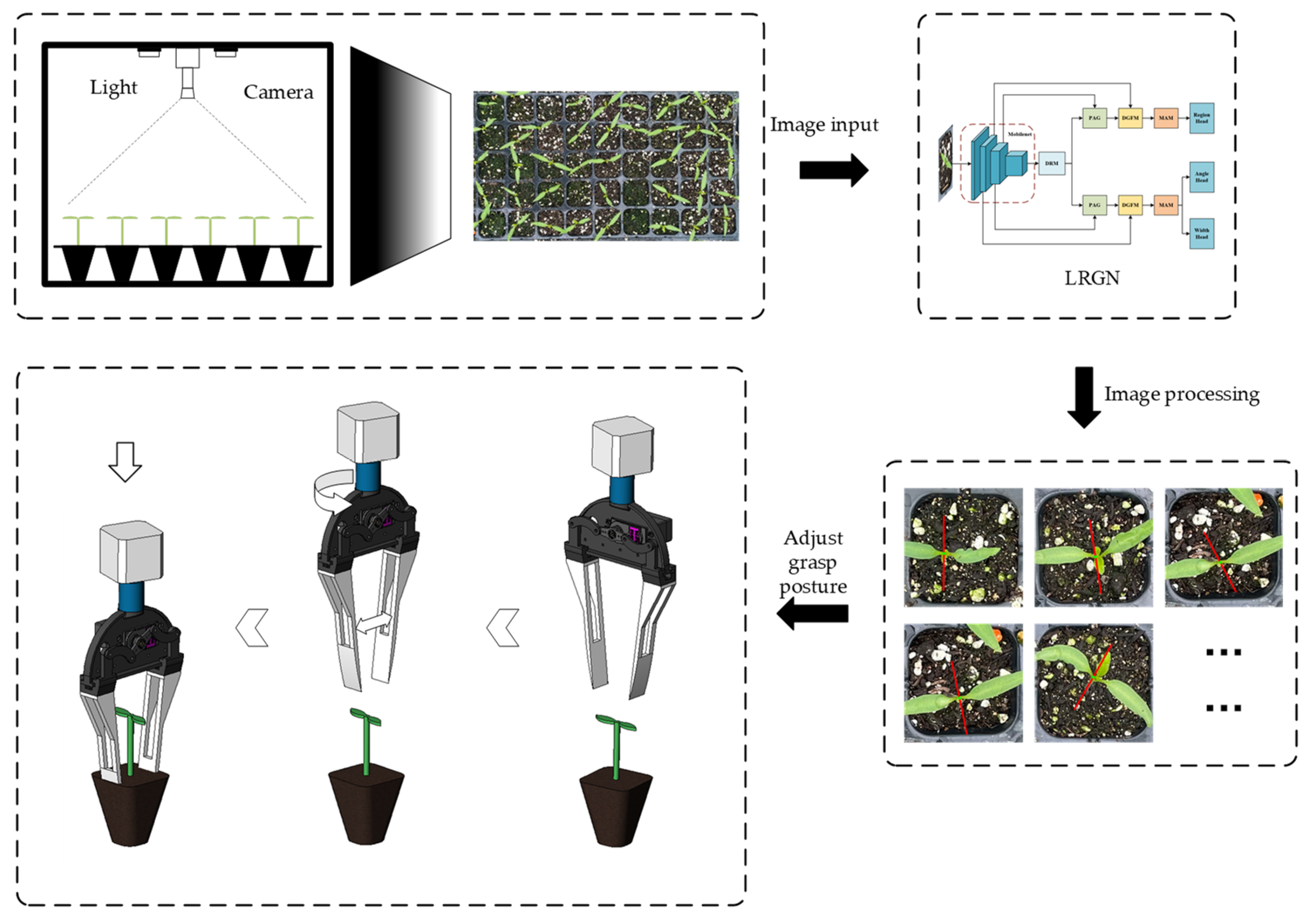
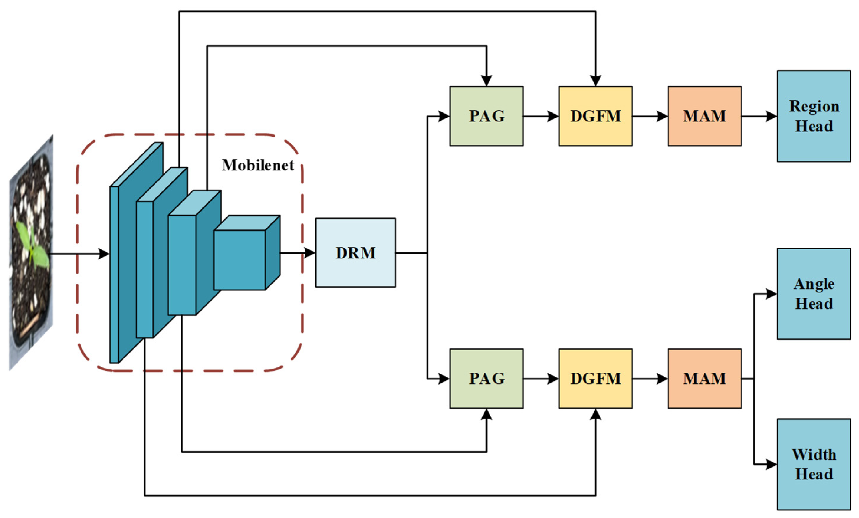
2.1. Overall Process Introduction

In this paper, a low-damage grasp method for plug seedlings is proposed, and its overall process is shown in Figure 2. Firstly, the 2D image of the whole tray of plug seedlings is captured in a light box to ensure that high-quality image data are obtained under uniform light conditions. Then, according to the size of the plug-hole, each plug seedling is segmented from the overall image and input into the designed lightweight low-loss grasping model LRGN, which automatically calculates the optimal grasping position of each plug seedling based on the input image, including key parameters such as grasp point, grasp angle, and grasp width. Finally, the system transmits the generated optimal grasp position information to an end-effector with two degrees of freedom, which performs a low-damage grasp operation according to the position to ensure that damage to the seedling is minimized during the grasp process.

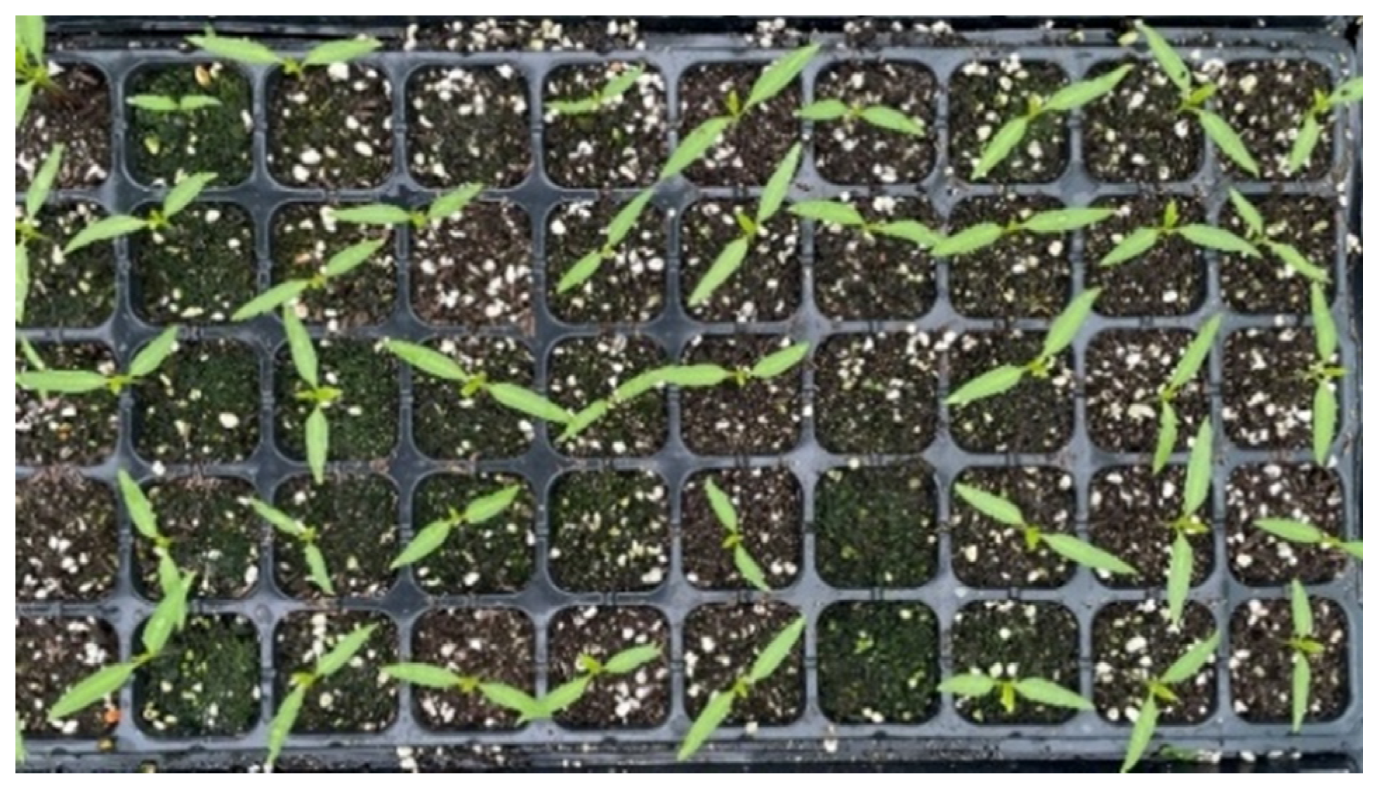
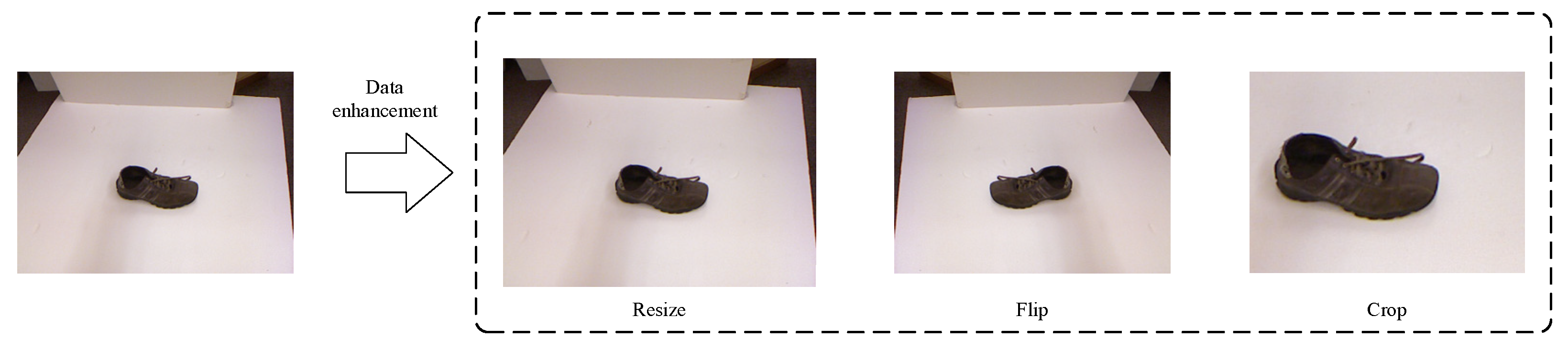
2.2. Image Data Collection

The data for this study were collected from Hengyang Vegetable Seed Company in Zhuhui District, Hengyang City, Hunan Province, on 5 January 2024, from chili pepper seedlings at the two-leaf-one-heart period. The image acquisition equipment was Hikvision’s MV-CU060-10GC (Hikvision, Hangzhou, China), and the images were taken vertically downward at a distance of 50 cm from the plugs using a fixed tripod. A total of 70 images were collected with a resolution size of 3072 × 2048, as shown in Figure 3. In this study, the grasp task focuses on the planar grasp of the plug seedling. In planar grasp, the grasped target is usually on a relatively fixed plane with relatively small changes in the height of the target. Therefore, the 2D image can provide enough feature information to identify the position and state of the grasping target without the need for additional depth information. Although RGB-D images do provide more comprehensive information in certain complex environments, the processing of added depth information may lead to additional computational overheads in the current research task without necessarily significantly improving the grasp results. Therefore, in this paper, we use 2D images as inputs to the grasp detection model.

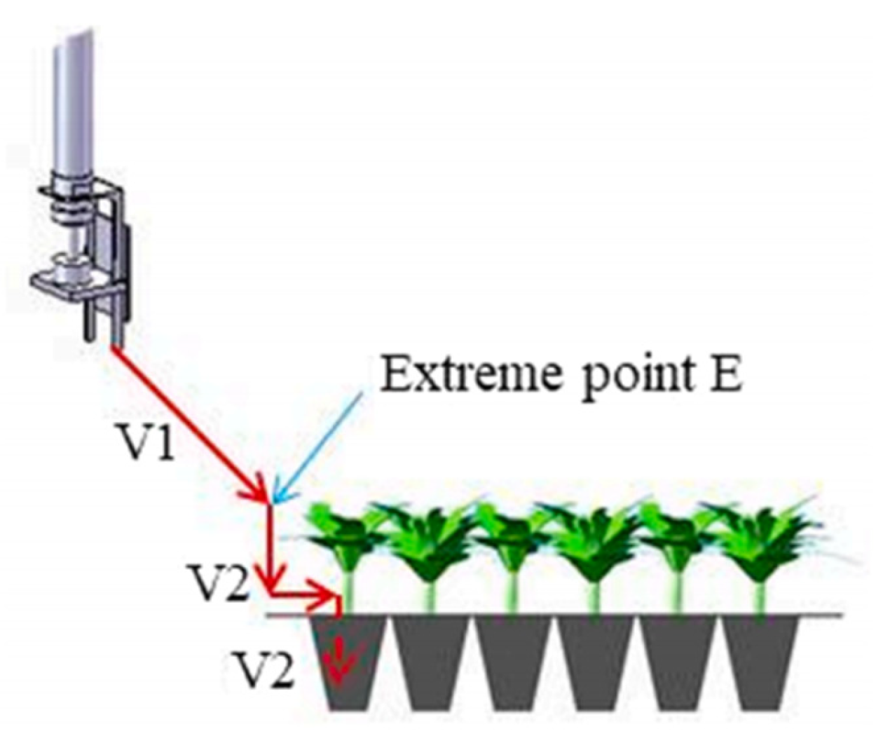
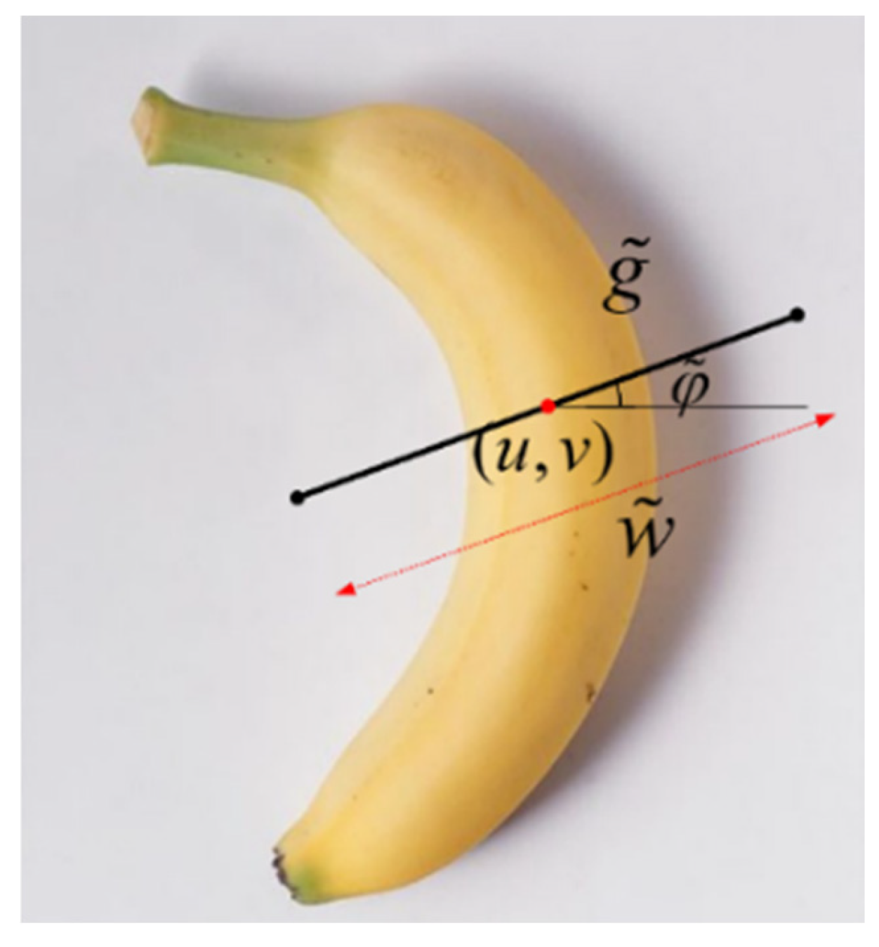
2.3. Grasping Representation of Two-Finger End-Effector

The planar grasping method is suitable for application in real industrial production, which restricts the robotic arm to perform only vertical desktop grasp tasks. Furthermore, it only requires the prediction of five parameters: [ x , y , z , θ , w ] . This method does not require the prediction of rotation parameters around the X-axis or the Y-axis. The robotic arm planar grasping method employs two distinct grasp representations: the directional rectangular box and the pixel-level. In this study, the pixel-level grasp detection method is utilized.
The pixel-point grasp method entails the generation of a grasp position for each pixel point in the image information, which comprises three elements: grasp point, grasp angle, and grasp width. This representation is depicted by Equation (1), which is illustrated in Figure 4.
g ˜ = [ u , v , φ ˜ , w ˜ ]
The grasp position in the world coordinate system g can be obtained from g ˜ by coordinate transformation. The transformation relation is shown in Equation (2):
g = t W C ( t C I ( g ˜ ) )
where t W C represents the transformation matrix between the world coordinate system and the camera coordinate system, while t C I denotes the mapping matrix between the 2D picture coordinate system and the 3D camera coordinate system.
Through the coordinate transformation of Equation (2), the pixel point grasping representation under the world coordinate system is shown in Equation (3):
g = [ x , y , z , φ , w ]
where ( x , y , z ) represents the positional information of the target object. φ denotes the rotation angle of the end-effector around the Z-axis, while w denotes the opening width of the end-effector. Since this task is a planar grasping task, the value of z is determined, so the grasping representation can be simplified as Equation (4).
g = [ x , y , φ , w ]

2.4. Grasp Detection Network

In this study, we propose a real-time grasp detection network LRGN (lightweight real-time grasp net) with RGB images as input, and an illustration of the network is shown in Figure 5. The LRGN mainly consists of a feature extraction part (Mobilenet), dilated refinement module (DRM), pixel-attention-guided fusion module (PAG), deep guidance fusion module (DGFM), mixed attention module (MAM), and prediction output head.
As shown in Figure 5, LRGN can be roughly divided into two parts: encoder and decoder. The encoder consists mainly of Mobilenet, DRM, PAG, DGFM, and MAM; the decoder consists of prediction output head, namely region head; angle head; and width head, which are responsible for decoding the grasping features extracted by the encoder into a heat map grasping representation.

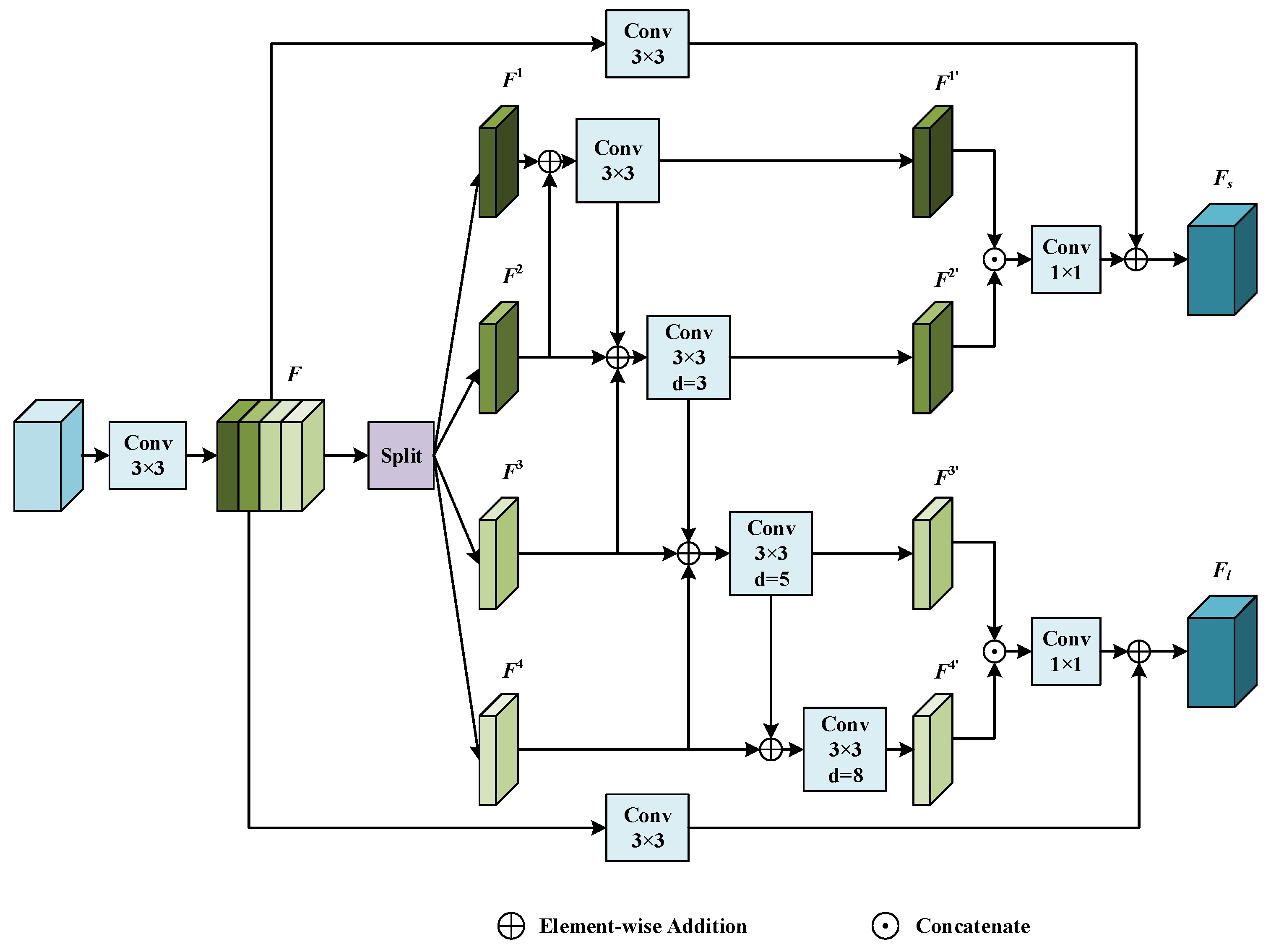
2.4.1. Dilated Refinement Module

Following the feature extraction by MobileNet, the input RGB image has rich global semantic information. Improving the global contextual information might have major accuracy advantages. Consequently, the module DRM for dilation refinement is meant to improve the global feature representation.
Figure 6 presents an illustration of the dilation refinement module. Four dilation convolutions with varying rates merged in parallel form its major component. The essence of the dilatation convolution in the figure is to “interpolate” into the regular convolution kernel, therefore extending the receptive field of the convolution kernel without raising the computational complexity and number of parameters.
First, a 3 × 3 convolution is used to adjust the number of channels of the input features to 1024. This results in feature F, which is then used to extract deep features. Then, F is divided into four sets of feature mappings {F1, F2, F3, F4} equally along the channel dimension. Next, a multiscale feature fusion method is employed to incorporate neighboring branch features at the pixel level. These features are then fed into various types of convolutional blocks to extract contextual features. The particular operation can be represented as Equation (5):
F m = C o n v ( F 1 + F 2 ) , m = 1 C o n v ( F m 1 + F m + F m + 1 ) , m = 2 , 3 C o n v ( F 3 + F 4 ) , m = 4
where Conv(∙) denotes four different convolution operations. For m { 1 , 2 , 3 , 4 } , Conv(∙) denotes a 3 × 3 convolution with a dilation rate of {1, 3, 5, 8}. Subsequently, we connect the first two branches and the last two branches along the channel dimensions, respectively, and then perform residual concatenation with feature F to obtain branch Fs with a smaller receptive field and branch Fl with a larger receptive field. Fs is used for predicting the grasping region, and Fl is used for predicting the grasp angle and width.

2.4.2. Pixel-Attention-Guided Fusion Module

PAG is a module for fusing P-branching and I-branching in PIDNet [14], and its simplified structure is shown in Figure 7. This module enables shallow features to selectively learn useful semantic information from deep features. Defining the vectors of corresponding pixels in the shallow feature map and deep feature map, respectively, the output of the sigmoid function can be expressed as Equation (6):
σ = S i g m o i d ( f l ( v l ) f h ( v h ) )
where σ denotes the probability that the two pixels belong to the same object. If σ is high, then trust v h more because the deep features are semantically rich and accurate, and vice versa. Therefore, the output of PAG can be written as Equation (7):
O u t p a g = σ v h + ( 1 σ ) v l

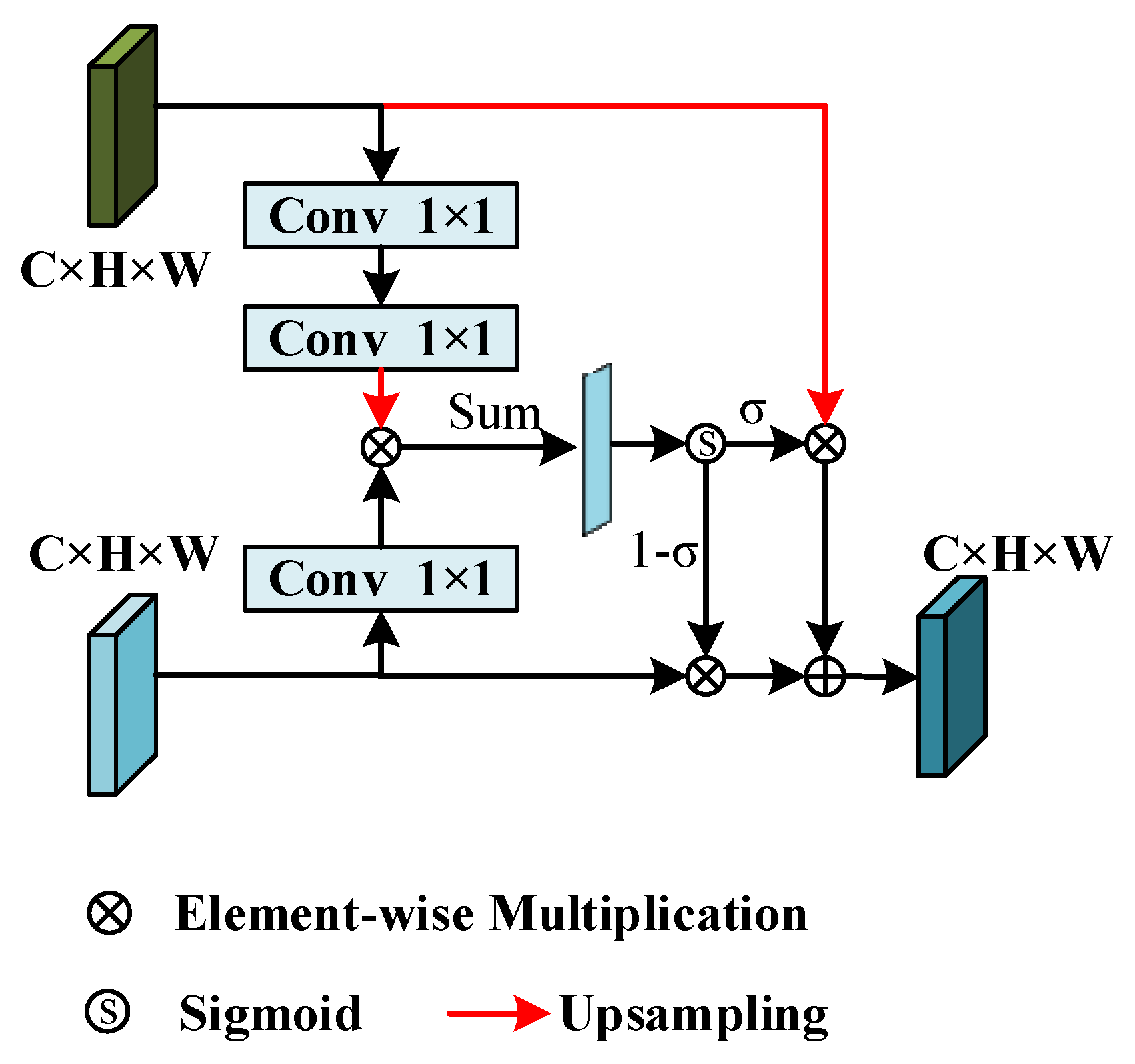
2.4.3. Deep Guidance Fusion Module

Understanding the relationship between deep semantic features and shallow detailed features is crucial. That is why a DGFM has been developed to help combine deep features and improve the representation of shallow features.
As shown in Figure 8, the DGFM utilizes a deep feature map F h i g h and a shallow feature map F l o w as inputs. The size of F h i g h is adjusted to match F l o w through upsampling. By utilizing a 3 × 3 convolution, the feature map is enhanced by increasing the number of channels to 256, resulting in a more enriched feature representation. The convolved deep feature F ¯ h i g h and shallow feature F ¯ l o w can be represented as (8) and (9):
F ¯ h i g h = C o n v 3 × 3 ( U P ( F h i g h ) )
F ¯ l o w = C o n v 3 × 3 ( F l o w )
where C o n v 3 × 3 ( ) denotes a two-dimensional convolution with 256 output channels and kernel size 3, and UP(∙) denotes the upsampling operation. The result of concatenating F ¯ l o w and F ¯ h i g h in the channel dimension is denoted as F c , and then F c is input to the global maximum pooling layer and the global average pooling layer, which are summed, and then the channels are tuned to multiply with F ¯ l o w by the 1 × 1 convolution and the sigmoid function, which can be denoted as (10):
F ^ l o w = F ¯ l o w σ ( C o n v 1 × 1 ( G A P ( F ¯ h i g h F ¯ l o w ) + G M P ( F ¯ h i g h F ¯ l o w ) ) )
where denotes feature concatenation, σ denotes the sigmoid function, GAP(∙) denotes global average pooling, GMP(∙) denotes global maximum pooling, C o n v 1 × 1 ( ) denotes a two-dimensional convolution with kernel size 1, and denotes pixel-level multiplication. The reconstructed shallow feature map is obtained by introducing a residual concatenation with the original input shallow features, and the feature representation is enriched by concatenating the shallow features with the deeper features as input to the next module.

2.4.4. Mixed Attention Module

In a grasp detection task, not all of the grasp features extracted by the network play a critical role in the final detection result. To solve this problem, an attention mechanism is introduced into the detection algorithm so that the network can selectively focus on important grasping features and ignore other irrelevant features. The attention mechanism is an additional special structure in the network that enables attention to important features by weighting the input features.
The channel attention mechanism proposed by Woo et al. in 2018 can adaptively adjust the importance of different channel features by learning the attention weights of input features in each channel [15]. Also, the coordinate attention mechanism proposed by Hou et al. in 2021 can adaptively adjust the importance of different spatial locations by learning the attention weights of input features in two different spatial directions [16]. In order to fully utilize the feature information in the channel dimension and the spatial dimension so that the detection algorithm can directly focus on the important grasping features in the channel dimension and the spatial dimension, the output features of the channel attention module and the coordinate attention module are fused to form the hybrid attention module. In addition, to enable the hybrid attention module to gradually learn the important grasping features, adaptive weights are introduced to fuse the module input features with the output enhancement features. An illustration of the MAM is shown in Figure 9. The output feature expression of the module is shown in Equation (11):
F M = F I C A M ( F I ) C A ( F I C A M ( F I ) ) + α F I
where F I and F M are the input and output features of the MAM, CA(∙) denotes the channel attention module, CAM(∙) denotes the coordinate attention module, denotes the pixel-level multiplication, and α is the adaptive weights with an initial value of 1.0 and adaptively adjusts the weights during the training process.

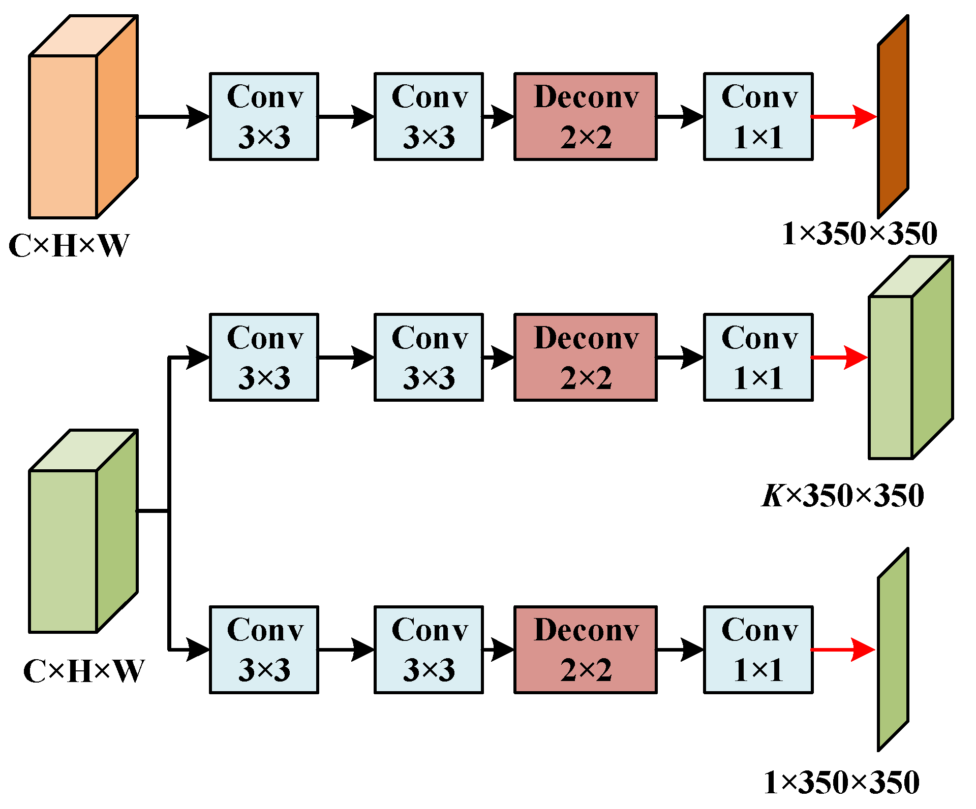
2.4.5. Prediction Output Head

With reference to AFFGA-Net [17], a prediction output head with three branches is designed, including the region head, angle head, and width head, where the input of the region head is the up-branch, and the number of channels is adjusted by two 3 × 3 convolutions, then a 2 × 2 transposed convolution is used for upsampling, and finally a feature map of the grasping points with the same size as the original map is obtained by a 1 × 1 convolution and bilinear interpolation. The input of the angle head and the width head is the down-branch, and the subsequent processing is the same as that of the region head, the difference being that the number of output channels of the angle head is K, which is taken as K = 120 in this study. Its structure is shown in Figure 10.
The region head outputs the confidence that each pixel point is in the grasp region R; the angle head outputs the category k of the grasp angle corresponding to each point, which is calculated based on θ = 2 π K k ; and the width head outputs the grasp width corresponding to each point. The point with the largest confidence level is selected as the grasping point ( x , y ) , and the grasping angle θ and the grasping width w are the prediction results corresponding to the position ( x , y ) . The optimal grasping model is determined by the grasp point ( x , y ) , grasp angle θ , and grasp width w .

2.5. Loss Function

Referring to AFFGA-Net [17], we calculate the loss for the output of each head separately and use the sum of the losses to optimize LRGN.
Grasp Region: The prediction of the grasp region is a binary classification problem. We first normalize the prediction results using the sigmoid function and then calculate the loss using the binary cross-entropy function (BCE), which is defined as follows:
L r e g = 1 N n = 0 N [ y q n log ( p q n ) + ( 1 y q n ) log ( 1 p q n ) ]
where N is the size of the output feature maps, p q n is the predicted probability of the nth position, and y q n is the label of the corresponding position.
Grasp Angle: After using the sigmoid function to normalize the output of the angle head, the grasp angle loss is calculated using the BCE function, which is defined as
L a n g = 1 N × L n = 0 N l = 0 L [ y l n log ( p l n ) + ( 1 y l n ) log ( 1 p l n ) ]
where p l n represents the probability that the predicted grasp angle is within [ l L × 2 π , l + 1 L × 2 π ] at the nth position and y l n is the corresponding label.
Grasp Width: The prediction of grasp width is a regression problem. We use the BCE function to compute the loss in the grasp width branch as follows:
L w i d = 1 N n = 0 N [ y w n log ( p w n ) + ( 1 y w n ) log ( 1 p w n ) ]
where p w n is the predicted grasp width at the nth position and y w n is the corresponding label.
Multitask Loss: In order to balance the losses in each branch, the final multitask loss is defined as
L t o t a l = γ 1 × L r e g + γ 2 × L a n g + γ 3 × L w i d
where γ 1 , γ 2 , and γ 3 are the weight coefficients of the loss. In this experiment, we set γ 1 = 1, γ 2 = 10, and γ 3 = 5.

3. Experimental Results and Analysis

3.1. Experimental Condition

The construction and training of LRGN is carried out in the Pytorch (2.0.1) deep learning framework and the programming language is Python (3.10). The computer operating system used for the experiments is Windows 10, the GPU is an NVIDIA GeForce RTX 3080, the processor is an Intel® Core™ i9-10900X @ 3.70GHz, and the RAM is 32GB. The training is performed using the Adam optimizer to optimize the network, the batch size is set to 16, the epoch is set to 200. The initial learning rate is set to 0.001, and the learning rate decays by 0.5 every 50 epochs during training.

3.2. Evaluation Metrics

A rectangular metric evaluation method is used to evaluate the crawl detection results of LRGN. It is defined as follows: the predicted grasp is correct if both the predicted grasp G p and the label G t satisfy the following two conditions.
The difference between the predicted grasp angle θ and the labeled grasp angle is less than 30°.
The Jaccard index of the predicted grasp G p and the label G t is higher than 0.25. The expression of the Jaccard index is as follows:
J ( G p , G t ) = G p G t G p G t
where G p G t is the size of the area of the intersection of the predicted grasp G p and the label G t , and G p G t is the size of the area of the concatenation of the predicted grasp G p and the label G t .

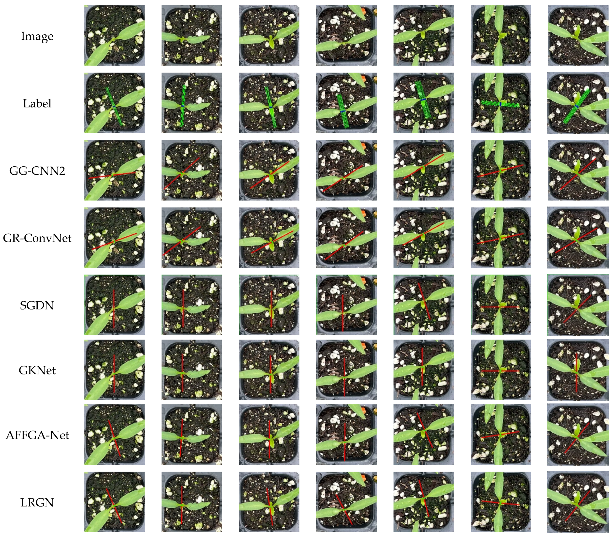
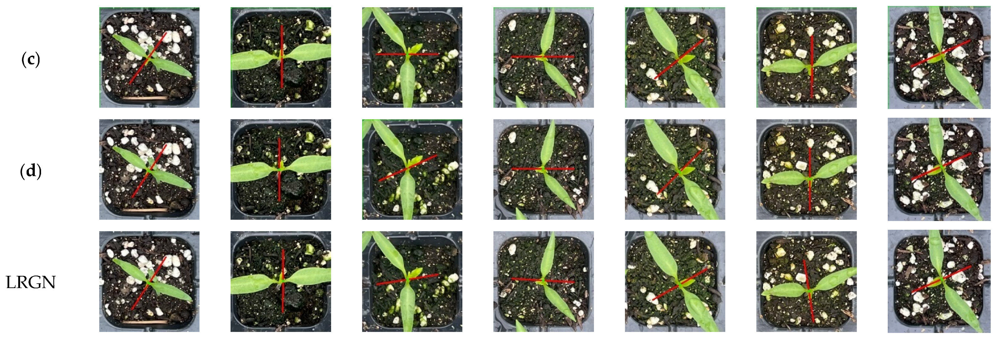
3.3. Experimental Results

3.3.1. Cornell Dataset

The LRGN is first trained and evaluated on the Cornell dataset [10]. The Cornell dataset is a publicly available dataset commonly used in robot grasping research, first released by Cornell University. The dataset contains a rich set of images and related grasp position information for training and testing deep learning models, and is widely used in the task of robotic manipulators grasping objects, especially in visually recognizing objects and determining appropriate grasp positions. The Cornell dataset contains 885 RGB images and depth images of 240 real objects in different positions and poses, each with a resolution of 640 × 480, and multiple labeled grasping rectangular boxes are provided in each image. The Cornell dataset is divided into two sub-datasets according to the image-wise and object-wise to validate the model’s discriminative and generalization ability. Image-wise splitting divides the dataset randomly, which is used to test the model’s ability to discriminate the grasping of objects with different angles and positions; object-wise splitting divides the images of the same object but with different angles into separate training or test sets, ensuring that the objects in the test set have not appeared in the training set, in order to validate the network’s ability to generalize the network in grasping unknown objects. Due to the small size of the Cornell dataset, in order to prevent the network from being trained to overfit, this paper uses flipping, cropping, and random scaling to enhance the data, as shown in Figure 11. The enhanced results are shown in Table 1. In this experiment, only RGB images are used as inputs, and the training and test sets are divided in a ratio of 4:1 and relabeled using a method established in the literature [17].
LRGN is a pixel-level grasp detection algorithm, so it generates predictive grasp for each pixel point of the input image, and only the grasp with the highest probability of grasp center is selected for evaluation during testing. The LRGN is compared with some representative existing grasp detection algorithms and the experimental results are shown in Table 2. Among them, the hyperparameters and training settings used by the comparative algorithm are the same as those of LRGN.
The results of the comparison experiments show that the GG-CNN2 network has a lower number of parameters, but its grasp detection accuracy is very low, only 73.00% and 69.00% in the image-wise and object-wise categories, which has a greater impact on the success rate of the grasp; the TsGNet network also has fewer parameters, and the FPS reaches 147, which is more real-time, but its grasp detection accuracy is still lower than the latest grasp detection networks. AFFGA-Net has the highest accuracy rate, with 99.09% and 98.64% in image splitting and object splitting, respectively, but it has a large number of parameters, which limits the real-time grasp detection of this network. The LRGN network proposed in this paper has high accuracy rates of 98.96% and 98.30% for image splitting and object splitting dataset division, which is slightly lower than AFFGA-Net, but its inference speed is 113 pcs/s, which is significantly higher than that of AFFGA-Net, and at the same time, the number of parameters is only 12.67 M, which is significantly reduced in accuracy and real-time detection, compared with other networks with high grasping accuracy, maintaining a good balance between accuracy and real-time performance.

3.3.2. Grasp Dataset of Plug Seedings

The captured images of plug seedlings were segmented and scaled according to the size of the plug-hole to obtain 852 images with a resolution of 350 × 350 to construct the grasp dataset of plug seedings, as shown in Figure 12a. The images were divided into training set and validation set in the ratio of 8:2, each image was labeled with the pixel-level grasp position using the literature method, and the principles of labeling were as follows: the grasp point was as close as possible to the center of the plug seedling, the direction of the grasp angle was perpendicular to the direction of the line connecting the two leaves, and the landing point of the clamping claw was as far away from the edge of the plug-hole as possible. The label is visualized as shown in Figure 12b.
The blue area in the figure is the graspable point, the angle between the direction of the green straight line and the horizontal direction is the grasping angle, and the length of the green straight line is the end-effector opening width. The labeled grasping set contains 2+K channels, which perform the following coding operations, respectively:
Grasp Confidence: The grasp confidence of each point is represented by a binary label, with the point in the labeled area assigned a value of 1 and all other points set to 0. The model predicts the grasp confidence in the feature map, with a higher value converging to 1, indicating a higher success rate of the grasp.
Grasp Angle: The grasping angle is constrained to the interval [0, 2π) and discretized from 0 to K. Consequently, the grasping angle label comprises K channels. In this experiment, K is set to 120, thereby indicating that each channel represents 3°.
Grasp Width: The widths of the labels in the dataset are all close to 200, which indicates that the grasping width takes on values within the range of [0, 200]. The parameter ω = 200 is set, and the value of the grasping width is scaled to the interval [0, 1) by 1/ω during training.
The LRNG is trained and evaluated on the collected dataset of grasping of plug seedlings. The LRGN is compared with the AFFGA-Net, GG-CNN2, and GR-ConvNet networks, selected with different backbone for grasp detection accuracy, floating point count, number of parameters, weight size, and FPS, respectively, and the results are shown in Table 3.
From the table, it can be seen that LRNG achieves the highest detection accuracy of 98.83% on the grasping dataset of plug seedlings, and the FPS is 113 frames/sec, which is only lower than that of GG-CNN2. The weight size obtained after training is only 46.3 MB, which can significantly reduce the model loading time and inference delay, and it would be relatively easy to be ported to devices such as cell phones, embedded systems, IoT devices, and other edge computing devices.
Some of the test results for LRNG and other networks on the grasp dataset of plug seedings are visualized in Figure 13. The red line represents the predicted optimal grasp position of the end effector. It can be seen that the grasp position detected by LRNG can better localize the seedling cores, and the landing point of its end- effector can avoid the seedling body and the edge of the plug-hole grid, thus achieving low-damage grasp. However, for seedlings that are particularly close to the edge of the plug-hole, the grasp position detected by the algorithm shows some limitations in balancing the avoidance of seedlings and avoidance of the edge of the plug-hole. When the seedling center is within 15 pixels of the hole edge, grasp detection accuracy drops by 3.2% on average compared to center positions. This decline is attributed to the increased background complexity and overlapping morphology near the edge.
To further validate the effectiveness of the proposed network, the Jaccard coefficient was increased from the initial 25% at 5% intervals to 35%; the larger the Jaccard index, the more demanding the grasping conditions and the more difficult it is to evaluate successful grasping. The accuracy of grasp detection with different Jaccard indexes is shown in Table 3. From the results in Table 4, it can be seen that, although the accuracy of the proposed network under a high Jaccard index is reduced compared to that under low Jaccard coefficients, even when the Jaccard index of the true value of the grasping region and the predicted grasping region is set at 35%, the network can still achieve accurate discrimination of the grasp position in most cases, with strong robustness.

3.3.3. Ablation Experiment

In order to validate the role of each module in the LRGN, ablation experiments are performed on each module in the same environment and using the same training details as above, and the results of the experiments are shown in the table. The baseline network in the table is the decoder added after Mobilenet, and the decoder uses the predicted output head from Section 2.4.5.
From the ablation experiment results in Table 5, it can be seen that, compared to the baseline network, the grasp detection accuracy is improved by 1.17% after adding the DRM; the grasp detection accuracy of the network is improved by 1.03% after adding the PAG; the grasp detection accuracy is improved by 1.31% after adding the DGFM; and the grasp detection accuracy is improved by 0.58% after adding the MAM. In order to prove the superiority of MAM, comparative experiments were conducted using EMA [25], CBAM [15], and ECA [26] to replace MAM, and the results of the experiments are shown in Table 6. From the results, it is evident that MAM is more advantageous compared to EMA, CBAM, and ECA. The experimental results are shown in Figure 14.
It can be seen that the algorithm’s detection accuracy on the grasp dataset of plug seedlings is significantly improved after adding these modules, while the impact on the detection speed of the algorithm is small, which leads to a further improvement in the overall performance of the algorithm.

4. Conclusions

To address the requirement of reducing seedling damage in the task of grasping plug seedlings, this study proposes a lightweight grasp position detection algorithm, LRGN, which can calculate the corresponding low-damage grasp positions for different plug seedlings in real time. The algorithm uses the lightweight network Mobilenet as the feature extraction network, and outputs two branches with different receptive fields through the dilated refinement module, and then enhances the algorithm’s expression ability of important grasp features and grasp perception ability for plug seedlings through the pixel-attention-guided fusion module, the depth-guided fusion module, and the mixed-attention module, which further enhances the grasp detection accuracy. The experimental results show that, compared with existing algorithms, the proposed algorithm balances detection accuracy and detection speed, performs well on both public and private datasets, and has strong generalization ability. The improved grasp detection speed (113 FPS) and accuracy (98.83%) of the proposed method help reduce damage to seedlings during transplantation, which directly translates to higher post-transplant survival rates and reduced need for manual sorting. This enhances transplantation efficiency and automation reliability, making the method highly applicable in agricultural production.
Although the method proposed in the thesis has better accuracy and real-time performance, there are some limitations. Firstly, the limitation of dataset size is an important limitation in this study. The experiments in this paper are based on a dataset containing 852 images, and although these images cover typical chilli pepper plug seedling grasping scenarios, the amount of data is relatively small and the scenarios are relatively simple. This means that the model’s ability to generalize to more complex or diverse environments is not yet fully validated. For example, the robustness of the model may be reduced under increased background complexity or greater variation in size and morphology of the plug seedling. Expanding the size of the dataset and adding diverse scenarios will be a key step in improving the generalization ability of the model in future studies. Secondly, there are limitations in the model’s ability to handle edge-grabbing locations. The experimental results showed that the detection accuracy of the model decreased when the plug seedling was close to the edge of the burrow. This was due to the complex background interference at the edge location and the irregularity of the seedling morphology, which posed an additional challenge to grasp detection. In addition, the model’s grasping accuracy was also reduced when the number of seedling leaves was high, due to the fact that occlusion would be formed between the leaves of the plug seedling, resulting in the model identifying the leaves of the neighboring burrow compartments as those of the burrow seedlings in this burrow compartment. In addition, challenges in real-world application environments are also factors that need to be further considered. In the experiments, although the model showed better real-time performance and accuracy in the simulated environment, in real industrial environments, the robot grasping task may face more uncertainties, and the ability of the existing model to cope with these uncertainties has not yet been sufficiently tested, and thus its deployment in real scenarios may require further optimization and adaptation.
Future work will focus on the following aspects: firstly, further enhancing the algorithm’s ability to handle complex grasping scenes, including grasping strategies for large-area and multi-layer blades; secondly, integrating it into an actual plug seedling transplanting robot system to verify the effectiveness and stability of the algorithm in practical production environments. This study provides an effective solution for the problem of seedling grasping in agricultural automation, and opens up new research directions for the application of machine vision and deep learning technology in intelligent agriculture.

Author Contributions

Conceptualization, F.Y. and Z.X.; methodology, F.Y.; software, G.R. and S.C.; validation, F.Y. and Z.Z.; formal analysis, Z.X. and Z.L.; investigation, G.R. and E.S.; resources, X.W. and G.M.; data curation, S.C. and Z.L.; writing—original draft, F.Y.; writing—review and editing, G.M., Z.Z. and X.W.; visualization, E.S.; supervision, Z.X. and X.W.; project administration, Z.X.; funding acquisition, Z.Z. and X.W. All authors have read and agreed to the published version of the manuscript.

Funding

This research was funded by the Natural Science Foundation of Hunan Province, China, grant number 2023JJ50125, and the Key Projects of Industry University Research Cooperation in Hengyang City, grant number 202320066437.

Data Availability Statement

The data presented in this study are available from the corresponding author upon request.

Conflicts of Interest

Author Zhenhong Zou was employed by the company Hengyang Vegetable Seeds Co. The remaining authors declare that the research was conducted in the absence of any commercial or financial relationships that could be construed as a potential conflict of interest.

References

  1. Peng, D. Mobile-based teacher professional training: Influence factor of technology acceptance. In Proceedings of the Foundations and Trends in Smart Learning. In Proceedings of 2019 International Conference on Smart Learning Environments, Denton, TX, USA, 18–20 March 2019; pp. 161–170. [Google Scholar]
  2. Zhao, X.; Guo, J.; Li, K.; Dai, L.; Chen, J. Optimal design and experiment of 2-DoF five-bar mechanism for flower seedling transplanting. Comput. Electron. Agric. 2020, 178, 105746. [Google Scholar] [CrossRef]
  3. Gao, G.; Feng, T.; Li, F. Design and optimization of operating parameters for potted anthodium transplant manipulator. Trans. CSAE 2014, 30, 34–42. [Google Scholar] [CrossRef]
  4. Wang, Y.; Yu, H. Experiment and analysis of impact factors for soil matrix intact rate of manipulator for picking-up plug seedlings. Nongye Gongcheng Xuebao/Trans. Chin. Soc. Agric. Eng. 2015, 31, 65–71. [Google Scholar] [CrossRef]
  5. Jin, X.; Tang, L.; Li, R.; Zhao, B.; Ji, J.; Ma, Y. Edge recognition and reduced transplantation loss of leafy vegetable seedlings with Intel RealsSense D415 depth camera. Comput. Electron. Agric. 2022, 198, 107030. [Google Scholar] [CrossRef]
  6. Liu, W.; Liu, J. Review of End-Effectors in Tray SeedlingsTransplanting Robot. J. Agric. Mech. Res. 2013, 35, 6–10. [Google Scholar] [CrossRef]
  7. Zhang, Z.; Lv, Q.; Chen, Q.; Xu, H.; Li, H.; Zhang, N.; Bai, Z. Status analysis of picking seedling transplanting mechanism automatic mechanism for potted flower. J. Jiangsu Univ. (Nat. Sci. Ed.) 2016, 37, 409–417. [Google Scholar]
  8. Kumi, F. Study on Substrate-Root Multiple Properties of Tomato Seedlings and Damage of Transplanting Pick-Up. Ph.D. Thesis, Jiangsu University, Zhenjiang, China, 2016. [Google Scholar]
  9. Ding, Y. Design and Experimental Study on Key Components of Automatic Transplanting Machine for Greenhouse Seedlings. Master’s Thesis, Zhejiang Sci-Tech University, Hangzhou, China, 2019. [Google Scholar]
  10. Lenz, I.; Lee, H.; Saxena, A. Deep learning for detecting robotic grasps. Int. J. Robot. Res. 2015, 34, 705–724. [Google Scholar] [CrossRef]
  11. Morrison, D.; Corke, P.; Leitner, J. Learning robust, real-time, reactive robotic grasping. Int. J. Robot. Res. 2020, 39, 183–201. [Google Scholar] [CrossRef]
  12. Tian, H.; Song, K.; Li, S.; Ma, S.; Yan, Y. Lightweight Pixel-Wise Generative Robot Grasping Detection Based on RGB-D Dense Fusion. IEEE Trans. Instrum. Meas. 2022, 71, 1–12. [Google Scholar] [CrossRef]
  13. Liu, D.; Tao, X.; Yuan, L.; Du, Y.; Cong, M. Robotic Objects Detection and Grasping in Clutter Based on Cascaded Deep Convolutional Neural Network. IEEE Trans. Instrum. Meas. 2022, 71, 1–10. [Google Scholar] [CrossRef]
  14. Xu, J.; Xiong, Z.; Bhattacharyya, S.P. PIDNet: A real-time semantic segmentation network inspired by PID controllers. In Proceedings of the IEEE/CVF Conference on Computer Vision and Pattern Recognition, Vancouver, BC, Canada, 17–23 June 2023; pp. 19529–19539. [Google Scholar]
  15. Woo, S.; Park, J.; Lee, J.-Y.; Kweon, I.S. Cbam: Convolutional block attention module. In Proceedings of the European Conference on Computer Vision (ECCV), Munich, Germany, 8–14 September 2018; pp. 3–19. [Google Scholar]
  16. Hou, Q.; Zhou, D.; Feng, J. Coordinate attention for efficient mobile network design. In Proceedings of the IEEE/CVF Conference on Computer Vision and Pattern Recognition, Nashville, TN, USA, 20–25 June 2021; pp. 13713–13722. [Google Scholar]
  17. Wang, D.; Liu, C.; Chang, F.; Li, N.; Li, G. High-performance pixel-level grasp detection based on adaptive grasping and grasp-aware network. IEEE Trans. Ind. Electron. 2021, 69, 11611–11621. [Google Scholar] [CrossRef]
  18. Redmon, J.; Angelova, A. Real-time grasp detection using convolutional neural networks. In Proceedings of the 2015 IEEE International Conference on Robotics and Automation (ICRA), Seattle, WA, USA, 26–30 May 2015; pp. 1316–1322. [Google Scholar]
  19. Kumra, S.; Kanan, C. Robotic grasp detection using deep convolutional neural networks. In Proceedings of the 2017 IEEE/RSJ International Conference on Intelligent Robots and Systems (IROS), Vancouver, BC, Canada, 24–28 September 2017; pp. 769–776. [Google Scholar]
  20. Asif, U.; Tang, J.; Harrer, S. GraspNet: An Efficient Convolutional Neural Network for Real-time Grasp Detection for Low-powered Devices. In Proceedings of the Twenty-Seventh International Joint Conference on Artificial Intelligence (IJCAI), Stockholm, Sweden, 13–19 July 2018; pp. 4875–4882. [Google Scholar]
  21. Wang, D. SGDN: Segmentation-based grasp detection network for unsymmetrical three-finger gripper. arXiv 2020, arXiv:2005.08222. [Google Scholar]
  22. Yu, Y.; Cao, Z.; Liu, Z.; Geng, W.; Yu, J.; Zhang, W. A two-stream CNN with simultaneous detection and segmentation for robotic grasping. IEEE Trans. Syst. Man Cybern. Syst. 2020, 52, 1167–1181. [Google Scholar] [CrossRef]
  23. Xu, R.; Chu, F.-J.; Vela, P.A. GKNet: Grasp keypoint network for grasp candidates detection. Int. J. Robot. Res. 2022, 41, 361–389. [Google Scholar] [CrossRef]
  24. Kumra, S.; Joshi, S.; Sahin, F. Antipodal robotic grasping using generative residual convolutional neural network. In Proceedings of the 2020 IEEE/RSJ International Conference on Intelligent Robots and Systems (IROS), Las Vegas, NV, USA, 25–29 October 2020; pp. 9626–9633. [Google Scholar]
  25. Ouyang, D.; He, S.; Zhang, G.; Luo, M.; Guo, H.; Zhan, J.; Huang, Z. Efficient multi-scale attention module with cross-spatial learning. In Proceedings of the ICASSP 2023–2023 IEEE International Conference on Acoustics, Speech and Signal Processing (ICASSP), Rhodes Island, Greece, 4–9 June 2023; pp. 1–5. [Google Scholar]
  26. Wang, Q.; Wu, B.; Zhu, P.; Li, P.; Zuo, W.; Hu, Q. ECA-Net: Efficient channel attention for deep convolutional neural networks. In Proceedings of the IEEE/CVF Conference on Computer Vision and Pattern Recognition, Seattle, WA, USA, 13–19 June 2020; pp. 11534–11542. [Google Scholar]
Figure 1. Machine vision group path. The red arrow represents the movement trajectory of the end effector, and the blue arrow is used to indicate the position of point E.
Agronomy 15 01376 g001
Figure 2. Overall process introduction.
Agronomy 15 01376 g002
Figure 3. Chili pepper seedlings at the two-leaf-one-heart period.
Agronomy 15 01376 g003
Figure 4. Pixel-level grasp representation.
Agronomy 15 01376 g004
Figure 5. Illustration of the LRGN.
Agronomy 15 01376 g005
Figure 6. Illustration of the dilated refinement module (DRM).
Agronomy 15 01376 g006
Figure 7. Illustration of the pixel-attention-guided fusion module (PAG).
Agronomy 15 01376 g007
Figure 8. Illustration of the deep guidance fusion module (DGFM).
Agronomy 15 01376 g008
Figure 9. Illustration of the mixed attention module (MAM).
Agronomy 15 01376 g009
Figure 10. Illustration of the prediction output head.
Agronomy 15 01376 g010
Figure 11. Data enhancement for the Cornell dataset.
Agronomy 15 01376 g011
Figure 12. Visualization of labeled images. (a) Original figure. (b) Label.
Agronomy 15 01376 g012
Figure 13. Test results on the grasp dataset of plug seedings.
Agronomy 15 01376 g013
Figure 14. Experimental results of the ablation experiment. (a) Mobilenet. (b) Mobilenet+DRM. (c) Mobilenet+DRM+PAG. (d) Mobilenet+DRM+PAG+DGFM.
Agronomy 15 01376 g014aAgronomy 15 01376 g014b
Table 1. Results of image augmentation for the Cornell dataset.
DatasetImagesTrainTestAugmentation
Techniques
Image Split35402832708Scale, Flip, Crop
Object Split35402728680Scale, Flip, Crop
Table 2. Results of different methods applied to the Cornell dataset.
MethodAccuracy/%FPSParams/M
Image-WiseObject-Wise
GG-CNN2 [11]73.0069.0052.620.06
AlexNet [18]88.0087.1013.207.30
ResNet-50 × 2 [19]89.2188.969.7025.56
GraspNet [20]90.6090.2042.603.71
SGDN [21]96.8092.2751.6015.31
TsGNet [22]93.1392.99147.000.20
GKNet [23]96.9095.7041.7015.74
AFFGA-Net [17]99.0998.6466.7068.11
LRGN98.9698.30113.0012.67
Table 3. Results of different methods applied to the grasp dataset of plug seedings.
MethodAccuracy/%Flops/MParams/MWeight/MBFPS
AFFGA-Net (resnet101) [17]97.9482,520.1468.1126650
AFFGA-Net (xception) [17]92.9879,844.5563.4824955
AFFGA-Net (drn) [17]96.25129,618.745.9718169
AFFGA-Net (mobilenet) [17]97.6654,800.1512.4246.6102
GG-CNN2 [11]73.913097.550.060.2653
GR-ConvNet [24]96.4932,368.611.97.2896
SGDN [21]97.6562,455.2315.3115251
GKNet [23]96.7756,420.6715.747341
LRGN98.8316,758.0312.6746.3113
Table 4. The accuracy of the proposed method under different Jaccard indexes.
MethodJaccard Index
0.250.300.350.40
LRGN99.4298.8396.4994.15
Table 5. Results of the ablation experiment on grasp dataset of plug seedings.
BaselineDRMPAGDGFMMAMAccuracy/%FPS
94.74210
95.91181
96.94170
98.25121
98.83113
Table 6. Results of experiments with different attention mechanisms.
ModelAccuracy/%FPSParams/M
+EMA98.7110612.65
+CBAM98.5611412.64
+ECA98.6211512.64
+MAM98.8311312.67
Disclaimer/Publisher’s Note: The statements, opinions and data contained in all publications are solely those of the individual author(s) and contributor(s) and not of MDPI and/or the editor(s). MDPI and/or the editor(s) disclaim responsibility for any injury to people or property resulting from any ideas, methods, instructions or products referred to in the content.

