Article

Characteristics of the Liquid Sheet of Air-Induction Spray

1
School of Agricultural Engineering, Jiangsu University, Zhenjiang 212013, China
2
School of Energy and Power Engineering, Jiangsu University, Zhenjiang 212013, China
*
Authors to whom correspondence should be addressed.
Agronomy 2025, 15(6), 1270; https://doi.org/10.3390/agronomy15061270
Submission received: 28 April 2025 / Revised: 15 May 2025 / Accepted: 20 May 2025 / Published: 22 May 2025
(This article belongs to the Special Issue Advances in Precision Pesticide Spraying Technology and Equipment)

Abstract

:
Spraying remains the primary method of pesticide application in plant protection, and spray drift is one of the important reasons that cause pesticide loss and environmental pollution. Air-induction spray is an anti-drift technology based on the Venturi effect. Unlike standard flat-fan sprays, the atomization mechanism of air-induction sprays has not yet been thoroughly studied. Therefore, a deep understanding of atomization and disintegration characteristics of air-induction spray liquid sheets is very important. This study utilized high-speed camera imaging technology to visualize the liquid sheet of air-induction sprays. Quantitative measurements were conducted on the disintegration length, spray angle, and bubble size of the liquid sheets. A comparative analysis was performed to examine the differences in liquid sheet structures between air-induction sprays and standard flat-fan sprays. The effects of different nozzle configurations and spray pressures on the liquid sheet of air-induction sprays were also discussed. The results indicate that bubbles are typical structures of the liquid sheets of the air-induction spray, and their disintegration can lead to perforations or interfacial disturbances in the liquid sheet. The study observed the coalescence of double or multiple bubbles within the liquid sheet, with atomized droplets potentially containing single or multiple bubbles. Compared to standard flat-fan sprays, air-induction sprays have smaller liquid sheet spray angles and disintegration lengths, by 23.48% and 16.32%, respectively. Bubble size decreases with increasing spray pressure but increases with larger nozzle orifice sizes. The spray angle of the liquid sheet significantly increases with higher spray pressures and larger nozzle orifice sizes. Meanwhile, the disintegration length of the liquid sheet shows a slight increase with rising spray pressures and larger nozzle orifice sizes.

1. Introduction

For pesticide application in plant protection, spraying is still one of the primary methods [1,2,3]. The drift of spray droplets is one of the significant factors that causes pesticide loss and environmental pollution [4,5,6,7]. In recent years, air-induction nozzles have been widely used to reduce spray drift [8,9,10,11]. However, the breakup mechanism of air-induction spray sheets is not clearly understood.
The air-induction nozzle has a Venturi structure [12], which can form a local low-pressure area. Air can be automatically sucked into the nozzle by the low pressure and mix with liquid, forming an air-liquid mixed flow [13]. This air-liquid mixed flow is intended to atomize bubble-containing spray droplets [14,15], which have relatively larger droplet sizes and contribute to reducing spray drift [16]. Moreover, the bubble within the droplet may disintegrate as the bubble-containing droplet impacts the target, generating more small droplets and enhancing the deposition [17,18]. The droplet size distribution, droplet velocity, and drift potential of air-induction spray have been widely investigated [14,19]. Currently, knowledge about the atomization process, especially how nozzle design and operational pressure affect droplet size, remains limited.
When liquid discharges from a nozzle, it typically forms a spray sheet, which subsequently breaks into droplets [20,21]. There is no doubt that the liquid sheet plays an important role in the atomization process of air-induction spray. Some research indicates that the disintegration length of the air-induction spray is apparently smaller than that of standard flat-fan spray [22]. At a certain flow rate, the thickness of the spray sheet released from a nozzle is, via a mass balance, inversely proportional to the disintegration length of the spray sheet [23]. In other words, thick spray sheets correspond to large droplets [24]. Therefore, a shorter disintegration length of the air-induction spray is conjectured to facilitate the generation of large droplets. Perforations were observed on the liquid sheet of the air-induction spray [22], and they are supposed to cause early disintegration of the spray sheet [24]. Perforations were also found in the liquid sheet of the oil-in-water emulsion spray [20]. The oil droplets are believed to be responsible for the generation of perforations in the oil-in-water emulsion spray [24]. However, the perforations in the liquid sheet of the air-induction spray can be generated when only water is sprayed. Clearly, they have different generation mechanisms. Moreover, perforations, bubbles are also the typical structures of the air-induction spray [22]; and the development of bubbles is possibly related to the formation of perforations.
In this paper, the atomization mechanism of air-induction spray was investigated. A high-speed camera was used to capture a liquid sheet of air-induction spray. Bubble disintegration in the spray sheet was studied. In addition, a theoretical hypothesis was proposed to explain these phenomena. The disintegration length, spray angle, and bubble size of the liquid sheet were measured. The effects of the nozzle type and spray pressure on the liquid sheet were discussed. This study contributes to a deeper understanding of the atomization mechanism of air-induction spray.

2. Materials and Methods

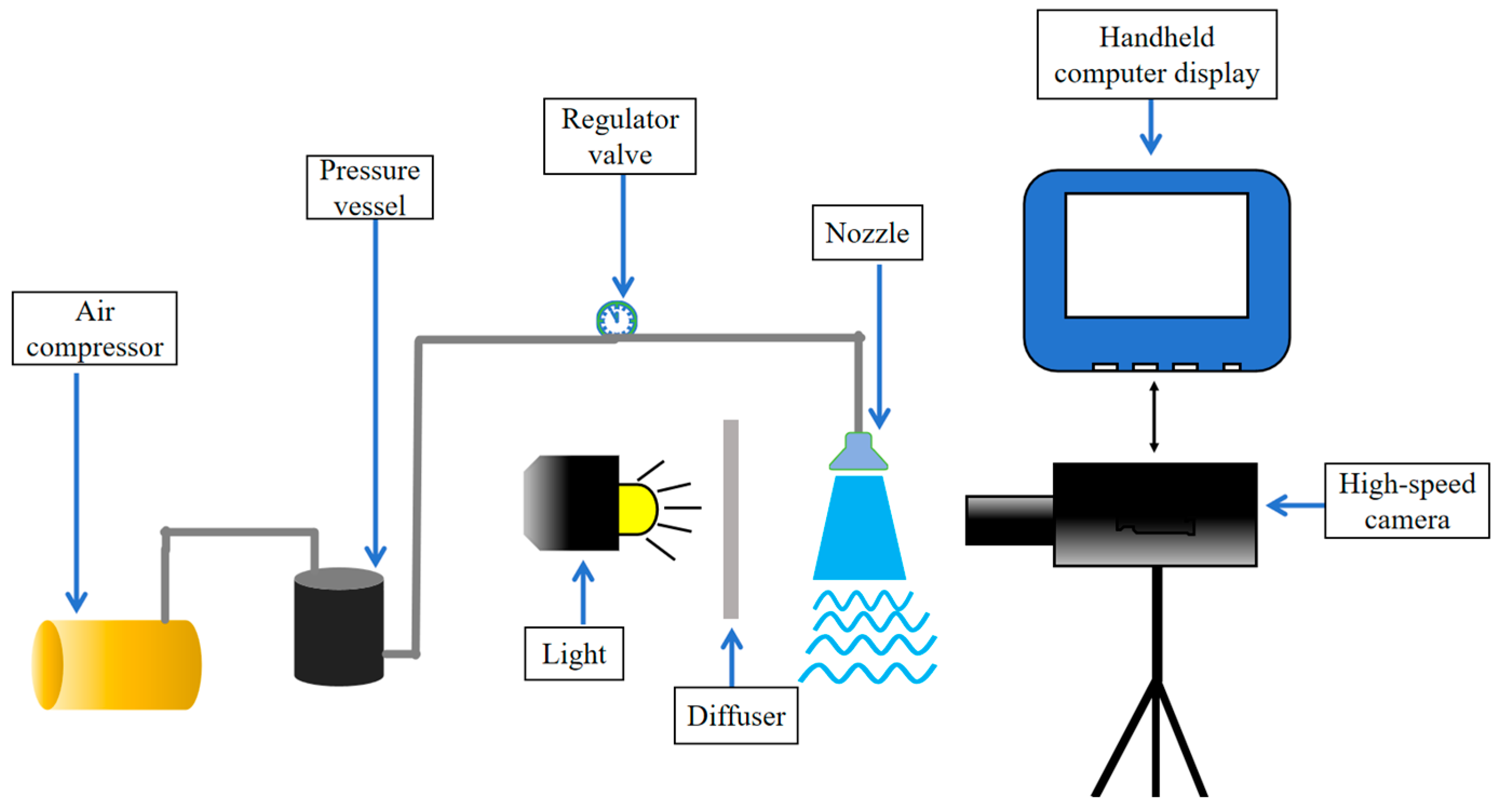
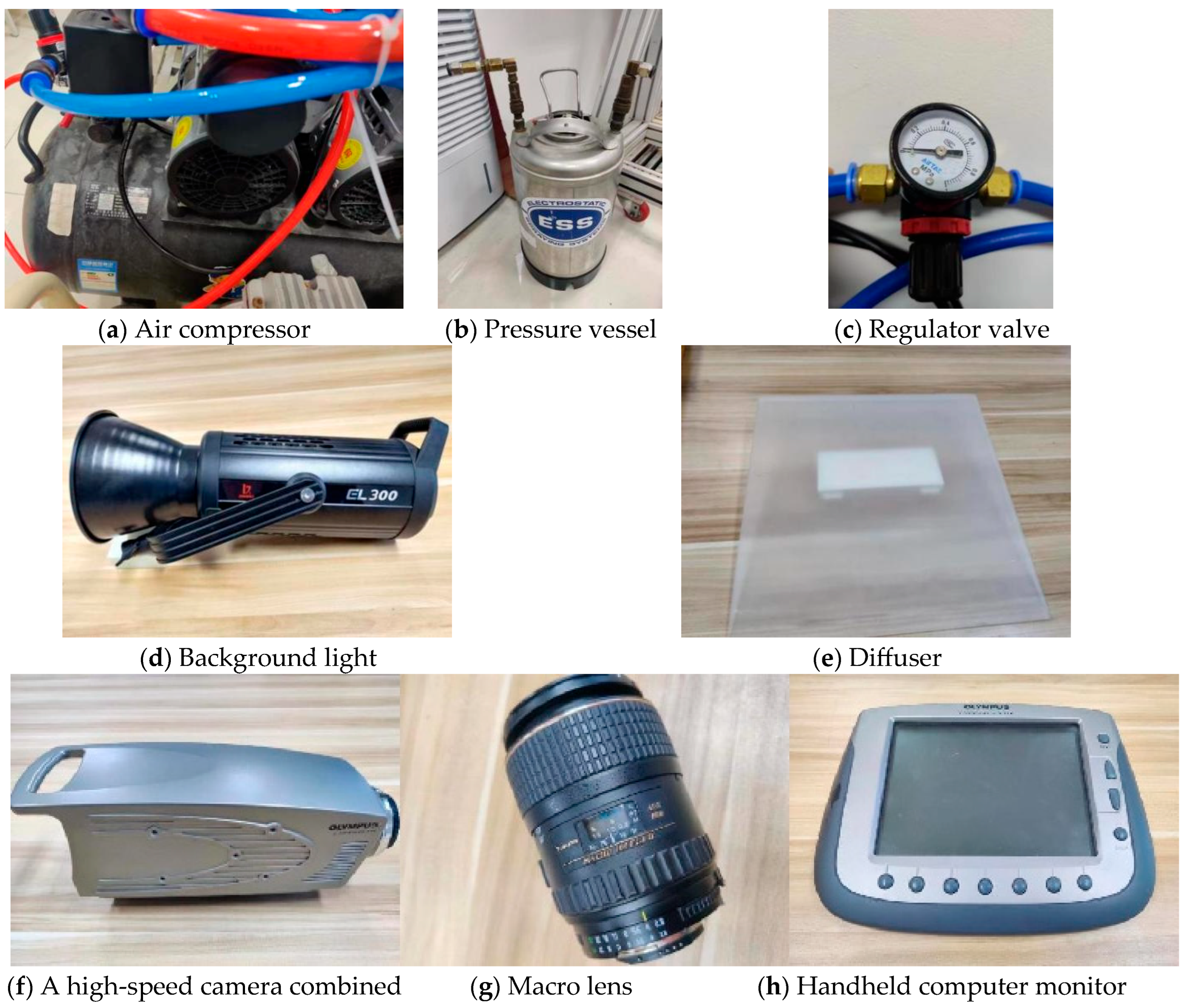
2.1. Experimental Setup

Figure 1 presents a schematic of the spray experiment setup, which mainly includes an air compressor, pressure vessel, regulator valve, light, diffuser, nozzle, spray liquid delivery tubing, high-speed camera, and handheld computer display.
Figure 2 shows the actual setup of the experimental devices. The air compressor (OTS-550×2, Taizhou Outstanding Industry and Trade Co., Ltd., Taizhou, Zhejiang, China) provides a maximum spray pressure of 0.7 MPa. The pressure vessel (ESS-XT, Spraying System Spray Systems Company, Shanghai, China) can withstand a maximum spray pressure of 0.90 MPa. The regulator valve (SMC AR-3000, SMC China Co., Shanghai, China, accuracy of 0.02 MPa) adjusts the spray pressure between 0 and 1 MPa. The background light illuminates the shooting area, with a brightness range of 0–100% and a maximum output of 33,000 lm. A diffuser between the nozzle and light source ensures uniform backlighting. The adjustable bracket positions the spray nozzle and adjusts the spray atomization capture space (precision: 0.02 mm). The high-speed camera (Olympus Co., Shinjuku-ku, Tokyo, Japan) with a lens (Tokina Macro 100 F2.8 D, Olympus Co., Shinjuku-ku, Tokyo, Japan) is placed horizontally, perpendicular to the spray atomization surface, for capturing high-quality images. It is connected to a handheld computer display for parameter adjustment and image preview. To capture transient spray structures, the exposure time of the high-speed camera was set to 2.16 μm. The frame rate was set to 2000 f/s, therefore, the time interval between adjacent images was 0.5 ms. Under these conditions, the image resolution was 1280 × 1024 pixels.

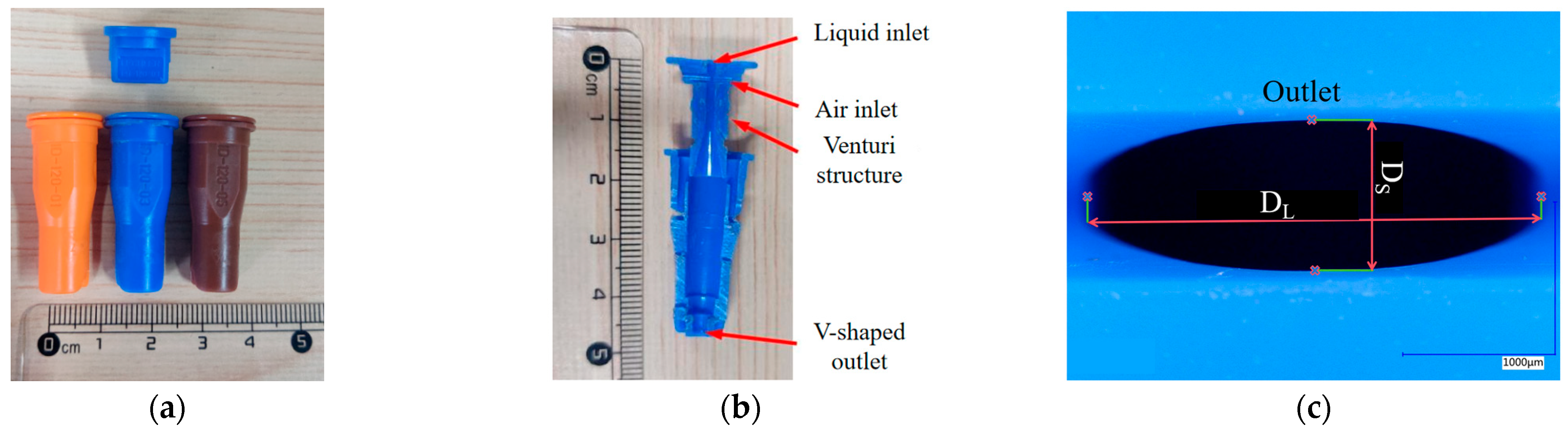
2.2. Structure of the Air-Induction Nozzle

In this experiment, the ID series air-induction nozzles produced by LECHLER Germany were selected (ID120-01, ID120-03, ID120-05, LU120-03, Lechler Inc., Metzingen, Germany), along with the standard flat-fan nozzle (LU120-03) from the same company for comparison with the ID120-03 air-induction nozzle. The effects of three pressures (0.1 MPa, 0.3 MPa, and 0.5 MPa) on the liquid sheet of air-induction spray were investigated using the ID120-03 nozzle. Figure 3 illustrates the structure of the air-induction nozzle.
For nozzles of the same type but different models, structural differences are indicated by model-specific parameters. When studying the impact of nozzle models on liquid sheet disintegration and droplet evolution, key structural parameters include the liquid inlet diameter (Dl), air inlet diameter (Da), V-notch angle (a), and nozzle exit dimensions. Given the elliptical nozzle exit, both the long diameter (DL) and short diameter (DS) are measured. The super-depth 3D microscope (VHX-900F, KEYENCE, Osaka, Japan) was used to measure these parameters for each nozzle, with results presented in Table 1.

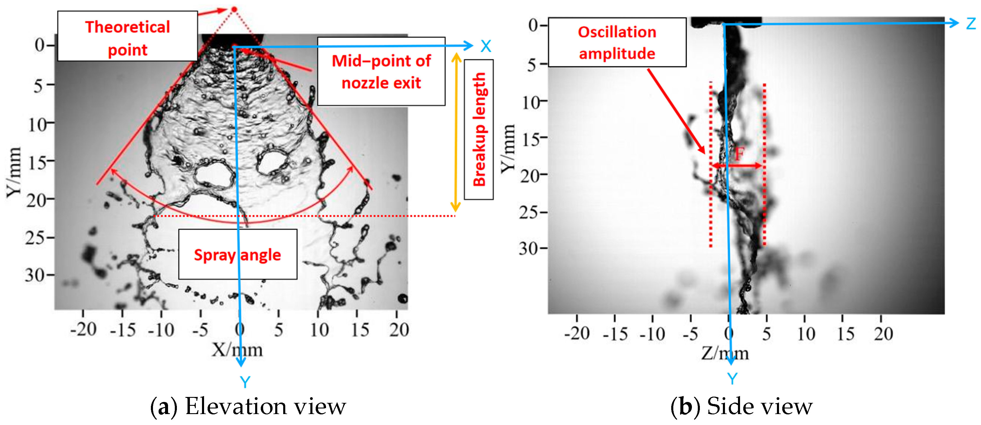
2.3. Image Processing

Image processing methods were used to process the spray images to obtain quantitative information about the spray sheet. As shown in Figure 4a, the center point of nozzle outlet is defined as the origin of all coordinates, with the horizontal (lateral) direction as the X-direction and the vertical downward (flow) direction as the Y-direction. The intersection point of the backward extensions of the edges (red solid line) on both sides of the liquid sheet is defined as the theoretical origin of the spray. The included angle is defined as the spray angle. The distance between nozzle exits and the vertical position where liquid sheet primary breakup (orange solid line) is defined as breakup length. The pressure used in Figure 4a is 0.1 MPa, and the spray angle is 75.3°. As shown in Figure 4b, the direction perpendicular to the XY-plane is defined as the Z-direction. The distance between two red dashed lines is defined as the fluctuation range.
Before the experiment, the actual length of the nozzle was measured using a ruler. The pixel length of the nozzle in the images is measured with the commercial image analysis software Image Pro Plus 8.0 (Meyer Instruments, Houston, TX, USA). Given the transient nature of atomization, to minimize measurement errors, 100 spray images, spaced 10 frames apart, were captured under different conditions. The average of these angles is taken as the spray angle for each condition. Typical measured results are shown in Figure 5. For this example, the average spray angle was 72.17° and the standard deviation is 5.06°.
The method employed to distinguish perforations from bubbles is based on successive images [25]. For the perforation, once it is generated, it will expand due to the surface tension. In contrast, the size of a bubble will not change significantly over time. One example is shown in Figure 6, as indicated by the blue arrows, bubble size exhibits no obvious change during the time span from T = 0.0 ms to T = 1.0 ms. However, for the perforation, as indicated by the red arrow, its size dramatically increases as T increases from 0.5 ms to 1.0 ms.

3. Results and Discussion

3.1. Study on Atomization and Disintegration Characteristics of Air-Induction Liquid Sheet

The air-induction nozzle has a special venturi structure. It automatically draws in outside air to the nozzle body, creating a two-phase air-liquid flow. This flow exits the nozzle in a hollow, fan-shaped structure. It then interacts with the surrounding air, breaking into ligaments and further atomizing into droplets, including larger ones containing bubbles.
Changes in the liquid sheet structure are crucial to the atomization and disintegration process, being the first step in atomization. To study the atomization and disintegration of air-induction spray liquid sheets and the bubble distribution on them, pure water was used as the spray liquid. To better analyze the bubble flow evolution in the spray liquid sheet, suitable spray parameters, including nozzle configuration and spray pressure, were chosen. After experiments, the combination of the ID120-03 nozzle and 0.1 MPa spray pressure was selected for its clear bubble evolution observation. Additionally, under the same conditions, the standard flat-fan nozzle LU120-03 was used for comparison. Figure 7 compares the liquid sheet atomization and disintegration characteristics under different spray conditions. Typical spray liquid sheet images are shown in Figure 7a–c. In the natural state (Figure 7a), bubbles and perforations are distributed on the liquid sheet. Compared to Figure 7b,c, the liquid sheet is shorter, and bubble rupture creates perforations, which increase liquid sheet oscillation and accelerate disintegration into ligaments or droplets of varying sizes. When the air inlet is blocked, no significant bubbles or holes form on the liquid sheet, and the spray fan structure resembles that of a standard flat-fan nozzle, although the liquid sheet is longer due to nozzle dimensions. The side view shows that blocking the air inlet reduces liquid sheet oscillation compared to the natural state. Air intake creates bubbles and perforations, and their rupture increases oscillation.
Figure 7d compares the spray angles of the liquid spray sheet under different spray conditions. The spray angles for the air-induction spray with the air inlet in its natural state, blocked state, and for the standard flat-fan nozzle are 72.17°, 77.58°, and 94.31°, respectively (with standard deviations of 5.06, 4.24, and 4.19). Blocking the air inlet of the air-induction nozzle increases the spray angle by about 7.50% due to reduced liquid sheet oscillation, fewer energy-losing bubbles and perforations, and greater lateral spread. The standard deviation is also smaller. Under the same spray pressure, the standard flat-fan spray has a spray angle about 30.68% larger than the air-induction spray, mainly due to differences in nozzle configuration and structure. The venturi structure of the air-induction nozzle reduces the pressure of the liquid exiting the nozzle, resulting in a smaller spray angle. Figure 7e shows the measured disintegration lengths of the liquid spray sheet. The presence of bubbles and perforations causes earlier disintegration, resulting in the shortest disintegration length of about 28.25 mm (standard deviation 2.77). Blocking the air inlet increases the disintegration length to about 44.25 mm (standard deviation 1.99), a 56.64% increase. The standard flat-fan spray has a disintegration length of about 33.76 mm (standard deviation 1.52), slightly longer than the air-induction spray.
From the experimental results, both the air-induction spray with a blocked air inlet and the standard flat-fan spray exhibit wavy liquid sheets, indicating that waviness is not the main cause of perforation. For air-induction sprays, the flow and evolution of the unique bubble structure on the liquid sheet are key factors affecting atomization and disintegration.
Analysis of continuous spray images from a high-speed camera reveals diverse bubble evolution behaviors on the liquid sheet. Some bubbles rupture directly, causing perforations. Figure 8 illustrates this process. At T = 0 ms, an intact bubble exists on the liquid sheet. It ruptures at T = 0.5 ms, creating a hole. The liquid sheet at the edge of the hole is thicker than the surrounding area. The hole then expands over time (T = 1 ms, 1.5 ms, 2 ms) and eventually leads to liquid sheet disintegration at T = 3.5 ms, producing ligaments or droplets of various sizes. This indicates that the perforation process occurs rapidly.
Another phenomenon observed in the experiment is that bubble rupture can indirectly induce perforation. Figure 9 shows the process where a bubble ruptures at T = 0.5 ms, forming a ripple structure with a small perforation in the middle. At T = 1 ms, a similar perforation structure to that in Figure 9 appears, with a significant increase in perforation area, eventually leading to liquid sheet disintegration at T = 2.5 ms. This suggests that bubble rupture may first create a ripple structure and liquid jet, with the jet causing perforation in the ripple. Here, the liquid jet is considered to change the liquid sheet thickness, leading to perforation. Therefore, bubble rupture is closely related to perforation.
Bubble rupture does not always cause perforation. Figure 10 shows that before rupture (at T = 0 ms and T = 0.5 ms), bubbles move on the spray liquid sheet, slightly changing shape. At T = 1 ms, the bubble ruptures, releasing gas due to the pressure difference. This causes interfacial oscillation on the spray liquid sheet, forming a ripple-like “depression” structure, thinner in the middle than at the edges. A dot-like structure appears in the middle, indicating liquid jet formation from bubble rupture. At T = 1.5 ms, this dot disappears, merging into the ripple. The pressure difference change from rupture causes edge liquid to be drawn inward, altering the sheet thickness and expanding the ripple while thinning it. Another reason is that after rupture, the bubble liquid sheet’s pressure drops to zero quickly, generating surface tension waves. The liquid sheet contracts under surface tension to fill the “depression” created from rupture. By T = 2 ms, the structure fades, ending the bubble rupture process without causing sheet disintegration.
Bubbles are a key feature of air-induction spray liquid sheets, spread across the entire sheet. As atomization proceeds, the number and size of the bubble can change in complex ways. In the positive Y-direction, the number of bubbles decreases while their sizes increase. Figure 10 shows a single bubble rupturing, which reduces bubble count. Figure 11 illustrates multiple-bubble rupture and evolution. At T = 0 ms, several bubbles are visible. By T = 0.5 ms and T = 1 ms, bubbles rupture, forming ripples that weaken and vanish, reducing the number of bubbles significantly in a short time.
Previous research has provided insights into the movement and distribution of bubbles on the liquid sheet, highlighting how bubble evolution, especially rupture-induced perforation, significantly affects liquid sheet disintegration. However, the exact conditions leading to perforation remain unclear. This study proposes a hypothesis to explain this phenomenon.
For perforation, bubble size and liquid sheet thickness are key parameters. Figure 12 illustrates bubble rupture-induced perforation using a side view of the spray atomization process. The spray liquid sheet, formed as the gas-liquid mixture exits the elliptical nozzle orifice, thins with distance from the nozzle. During this process, bubbles may coalesce or rupture.
In one scenario (Figure 12a), a large bubble coalesces and reaches both sides of the liquid sheet, creating a thin liquid layer between the bubble and the sheet due to bubble compression. As the sheet thins and the liquid layer is subjected to capillary pressure from interfacial curvature, the layer thins further until it ruptures (Figure 12a, process ⑤), potentially on both sides. The higher air pressure within the bubble causes air to escape upon rupture, disrupting the liquid sheet’s force balance. The remaining thin layer then ruptures rapidly (Figure 12a, process ⑥), forming a perforation, consistent with Figure 8.
In another scenario (Figure 12b), smaller bubbles only reach one side of the liquid sheet, forming a thin liquid layer on that side. When this layer ruptures, air escapes from the bubble, causing a force imbalance. The surrounding liquid is then drawn into the rupture site (Figure 12b, process ⑤, green arrow), adjusting the local liquid sheet thickness. If the surrounding liquid sheet is thin enough, it tears directly, creating a perforation. If not, the thickness readjusts, and no perforation occurs.
Bubble coalescence also reduces their number. Two typical scenarios are shown in Figure 13. In Figure 13a, two bubbles approach and collide at T = 0 ms. The liquid sheet separating them thins and forms a concave structure at T = 0.5 ms, accelerating coalescence. By T = 1 ms, the concave structure develops further, leaving a very thin liquid sheet between the bubbles. As more liquid drains, the sheet ruptures, and the two bubbles merge into a larger one at T = 1.5 ms. This newly formed bubble causes a rippling disturbance, indicating interfacial oscillation from the coalescence. By T = 2.5 ms, the bubble reaches a stable state. Multiple bubbles also coalesce in a similar way, as shown in Figure 13b, which is not detailed here. Bubble coalescence reduces the number of bubbles and increases their size.
As shown in Figure 14, to better illustrate the bubble coalescence process on a planar liquid sheet, a diagram is presented, dividing coalescence into six stages: intact bubbles, approaching and compressing, colliding, merging, oscillating, and finally stabilizing. Initially, as shown in process ①, two bubbles separated by a distance “H” (the thickness of the liquid sheet between bubbles) appear on the liquid sheet. They then move closer, compressing the liquid and thinning the sheet, which causes deformation. In process ③, the sheet thins further; when the bubbles are close enough, their surfaces become parallel, leading to coalescence. The sheet becomes so thin that it ruptures, merging the bubbles into an irregular shape (process ④). The new bubble oscillates due to uneven internal pressure and eventually stabilizes as a larger bubble (process ⑥).
Another distinctive feature of air-induction spraying is the formation of large bubble-containing droplets during atomization and disintegration. Previous studies have shown that bubble-containing droplets c can be collected using petri dishes filled with silicone oil for direct observation [17,26]. However, the formation mechanism of bubble-containing droplets in air-induction sprays remains unclear. This study explores how bubble-containing droplets form and evolve. Figure 15 captures the process of bubble entry into droplets to form bubble-containing droplets. In Figure 15, a single bubble moves towards the liquid sheet edge at T = 0 ms, 0.5 ms, and 2 ms. It is then entrained by the edge liquid, and the liquid sheet breaks up to form a ligament containing the bubble at T = 4.5 ms. Due to surface tension, the ligament tail contracts, and a large droplet containing a single bubble is formed at T = 5 ms. This droplet oscillates and stabilizes at T = 6 ms. The droplet size is visibly larger due to the enclosed gas. Figure 15b shows another formation mode of bubble-containing droplets, where multiple bubbles enter a droplet, forming a droplet containing several bubbles. Both processes occur within milliseconds.
The atomization of air-induction sprays involves gas-liquid two-phase flow, where gas (as a discrete phase) is distributed as bubbles on the spray liquid sheet (continuous phase), a signature feature of this spray type. Analyzing these bubbles’ motion improves our understanding of the liquid sheet’s disintegration in air-induction sprays.
During atomization, bubbles on the spray liquid sheet are influenced by forces such as surface tension [27], gravity [28], buoyancy [29], drag [30], and additional forces. For these bubbles, buoyancy and drag from the continuous phase (spray solution) resist their motion, while the additional force drives their movement. Key factors affecting bubble motion include bubble properties (size and shape), gas/liquid physicochemical characteristics (viscosity, density, and surface tension), liquid flow conditions, and environmental factors (temperature, humidity, pressure, and electric and acoustic fields) [31,32]. Here, the gravitational effects on bubbles are negligible.
Studying individual bubble motion is essential for understanding the movement of bubble clusters on the liquid sheet. Figure 16 shows bubble evolution and trajectories on the liquid sheet. Bubbles are released from the nozzle orifice at a certain velocity, primarily influenced by forces in the Y-direction, and evolve on the spray liquid sheet. The first motion state is defined as T = 0 ms. Bubble trajectories vary over time, and under 0.1 MPa spray pressure, the trajectory is nearly straight, indicating consistent resultant force direction. Bubble motion is transient and continuous, with each subsequent state influenced by the previous one. Trajectory images show oscillatory, non-equilibrium motion, with shape changes and slight size increases due to liquid sheet thinning and squeezing during atomization. Bubble coalescence, as shown in Figure 16, also contributes to size increase.

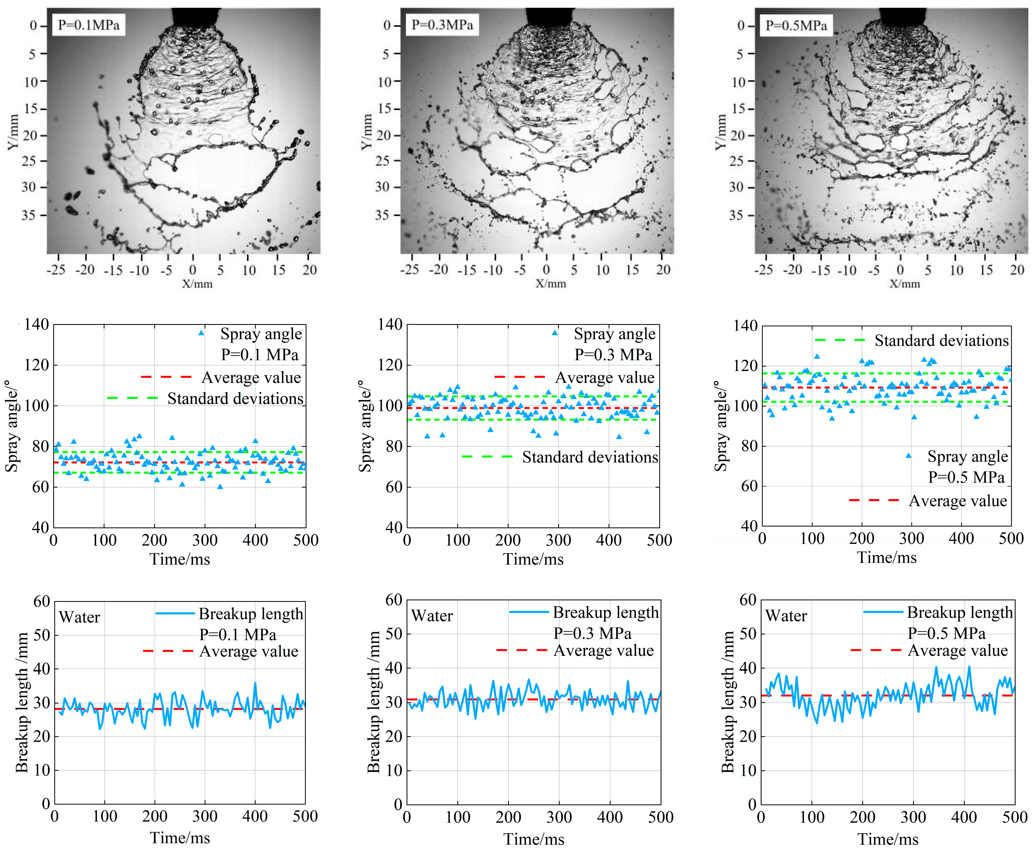
3.2. The Effect of Spray Pressure on Liquid Sheet of Air-Induction Spray

The effect of spray speed on bubbles was assessed by changing the spray pressure. Figure 17 shows bubble images and size distributions on the liquid sheet under these pressures. Results indicate that bubble count increases and bubble size decreases with higher spray pressure. At 0.1 MPa, 0.3 MPa, and 0.5 MPa, average bubble sizes were 354.32 μm, 246.67 μm, and 230.81 μm, respectively, showing significant size reduction at higher pressures. Bubble size distributions under different pressures were fitted to log-normal distributions with R2 values of 0.93, 0.95, and 0.96. At 0.1 MPa, bubbles were largest with the widest size distribution and fewest small bubbles (diameter < 300 μm, at 29%). At 0.5 MPa, bubbles were smallest with the narrowest size distribution and the most small bubbles (68%). As spray pressure increased, the proportion of small bubbles on the liquid sheet rose. Lower spray pressures result in less gas intake, lower liquid kinetic energy in the nozzle, and weaker gas-liquid mixing, leading to mostly large bubbles on the sheet. Higher spray pressures increase gas intake, liquid kinetic energy, and mixing intensity, causing gas to be sheared into more small bubbles, thus increasing bubble count and reducing size.
As shown in Figure 18, the spray angle and disintegration length were measured based on liquid sheet images captured under different spray pressures. The spray angle increases with higher spray pressure because the liquid gains more kinetic energy, leading to greater lateral expansion of the liquid sheet. Specifically, the spray angles at 0.1 MPa, 0.3 MPa, and 0.5 MPa were 72.17°, 98.92°, and 109.24°, respectively. The highest spray pressure of 0.5 MPa resulted in a significantly larger spray angle due to the increased number of bubbles and more intense liquid sheet disintegration. Compared to 0.1 MPa, the spray angle increased by 37.06% at 0.3 MPa and by 51.36% at 0.5 MPa. Although spray pressure greatly affects liquid sheet expansion and spray angle, this increase in spray angle is limited at very high pressures. Meanwhile, the increase in spray pressure also led to an increase in the liquid sheet disintegration length, with average disintegration lengths of 28.25 mm, 30.91 mm, and 32.06 mm at 0.1 MPa, 0.3 MPa, and 0.5 MPa, respectively. In summary, higher spray pressures increase both the spray angle and the liquid sheet disintegration length.

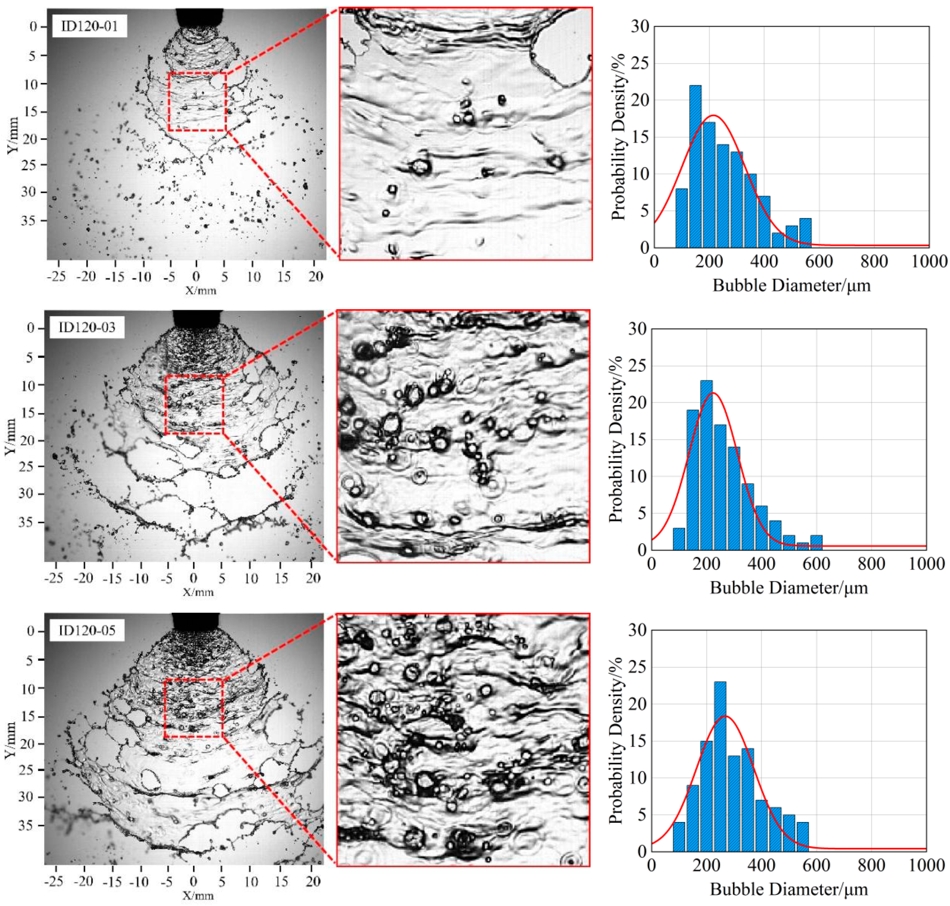
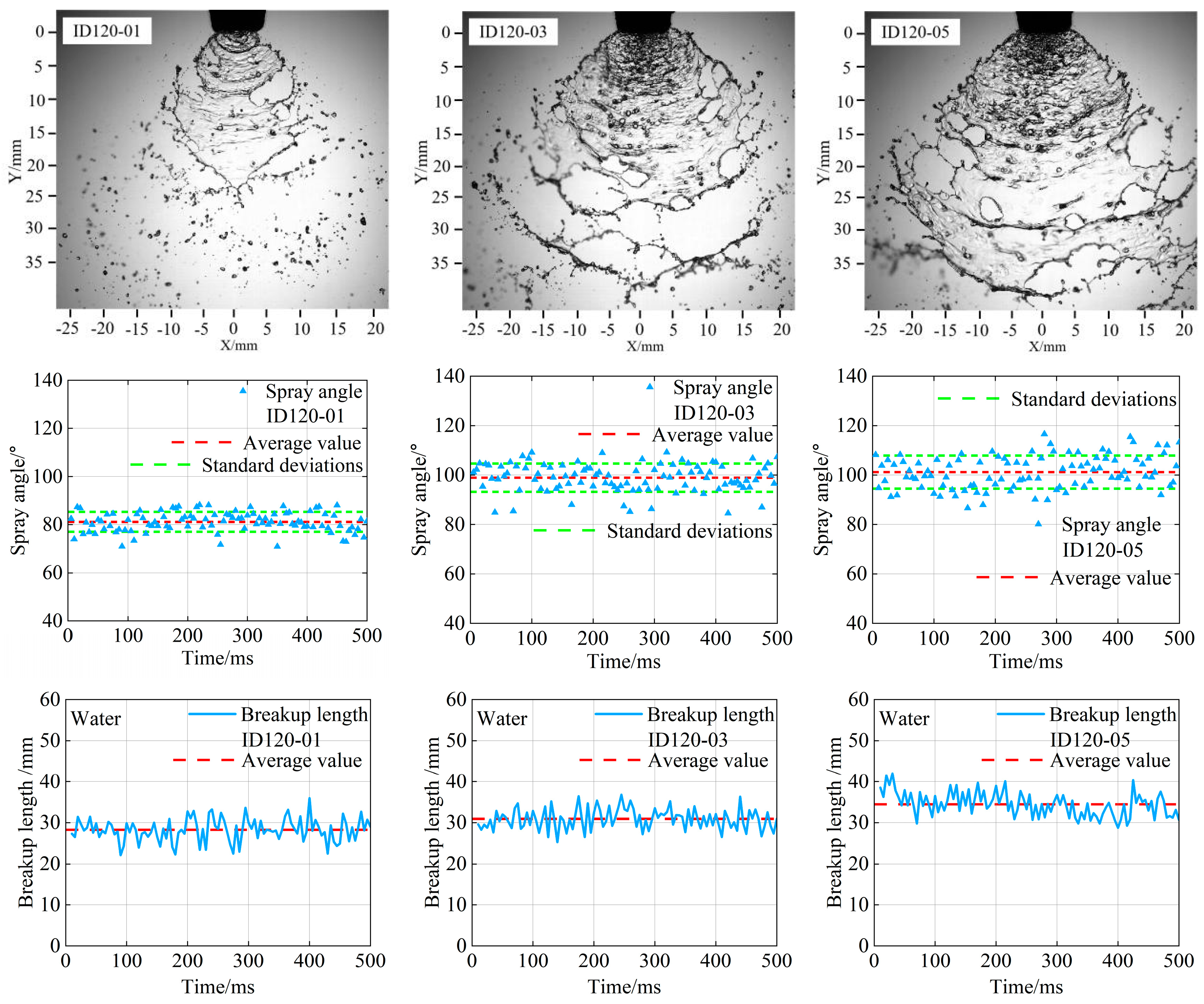
3.3. The Effect of Nozzle Structure on Liquid Sheet of Air-Induction Spray

The effect of nozzle structure on bubbles in the spray liquid sheet was studied using nozzles ID120-01, ID120-03, and ID120-05 at 0.3 MPa spray pressure. Figure 19 shows bubble images and size distributions on the liquid sheet for each nozzle. The morphology of the liquid sheet varies significantly among the nozzles. With the ID120-01 nozzle, the lateral spread is limited, resulting in a smaller liquid sheet area with very few bubbles. In contrast, using the ID120-03 and ID120-05 nozzles leads to larger liquid sheet areas with significantly more bubbles, particularly near the nozzle orifice, where a bubble-laden structure is observed. This is because, at the same spray pressure, the liquid and gas intake increase with nozzle size, primarily due to dimensional differences. The average bubble sizes for the ID120-01, ID120-03, and ID120-05 nozzles were 237.25 μm, 246.67 μm, and 272.17 μm, respectively, indicating a slight increase in bubble size with larger nozzles. Bubble size distributions under different nozzles were fitted to log-normal distributions with R2 values of 0.94, 0.95, and 0.94.
Figure 20 presents the spray angles and disintegration lengths of the liquid sheet under different nozzle models. The spray angles formed by the ID120-01, ID120-03, and ID120-05 nozzles were 81.12°, 98.92°, and 101.20°, respectively, with standard deviations of 4.11, 5.70, and 6.69. These angles gradually increased, consistent with the trend of decreasing bubble size on the liquid sheet. Under a certain spray pressure, the spray liquid forms a liquid sheet as a jet, and the spray angle, mainly influenced by the nozzle orifice size, was affected by the orifice dimensions shown in Table 1, with larger orifice sizes leading to larger spray angles. The increase in liquid intake with the nozzle model significantly affected the liquid sheet disintegration length. The average disintegration lengths for the ID120-01, ID120-03, and ID120-05 nozzles were 23.86 mm, 30.91 mm, and 34.45 mm, respectively. The ID120-01 nozzle had smaller spray angles and disintegration lengths due to its lower liquid intake and smaller orifice size.

4. Conclusions

In this study, a visual experimental method was used to investigate the atomization and disintegration characteristics of air-induction spray liquid sheets. The results are summarized as follows:
(1)
Air-induction sprays have a distinct liquid sheet disintegration structure compared to standard flat-fan sprays, with significant bubble and perforation presence on the liquid sheet. Bubble rupture induces perforation, increasing the sheet’s lateral oscillation amplitude. Differences in nozzle configuration, affecting structural dimensions and liquid sheet disintegration, significantly influence the spray angle and disintegration length. Compared to standard flat-fan sprays, air-induction sprays have smaller liquid sheet spray angles and disintegration lengths, by 23.48% and 16.32%, respectively.
(2)
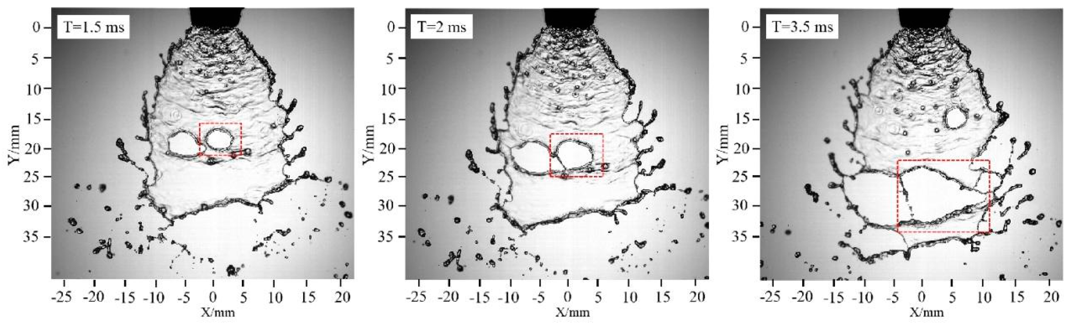
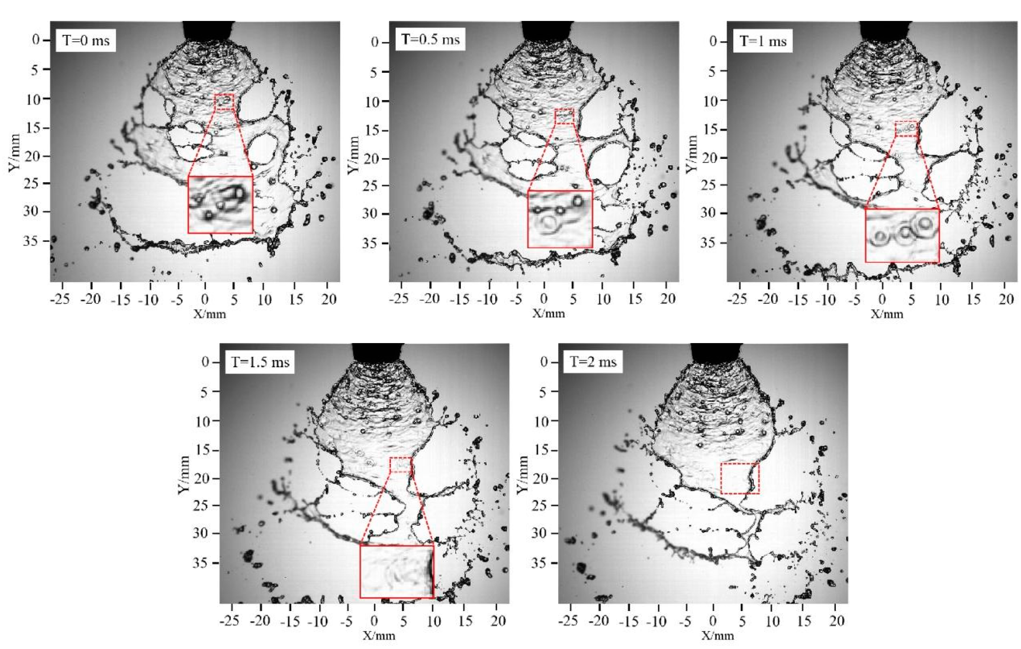
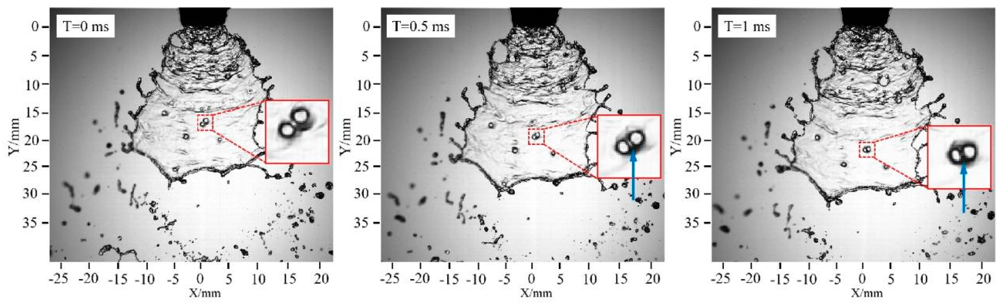
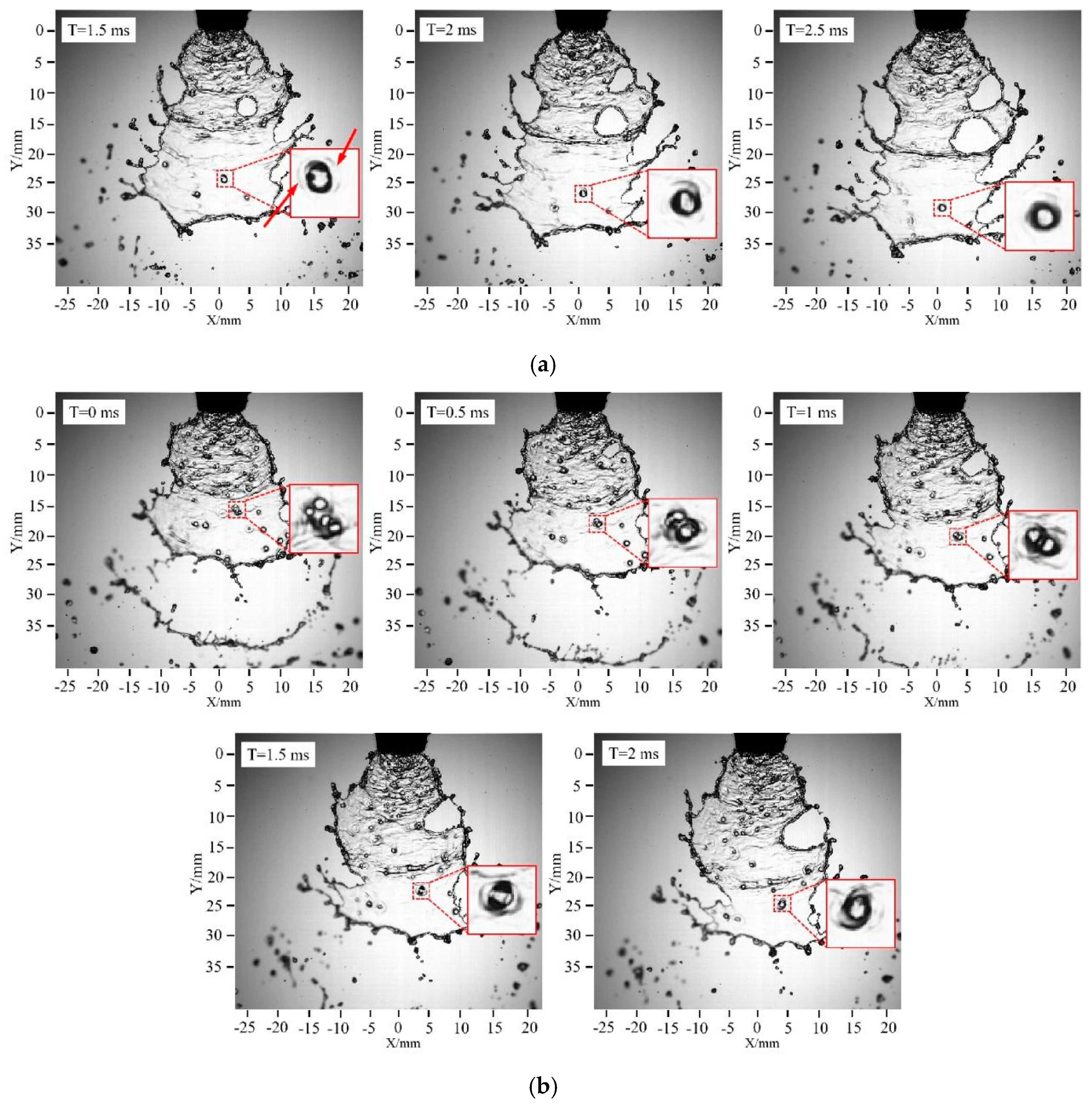
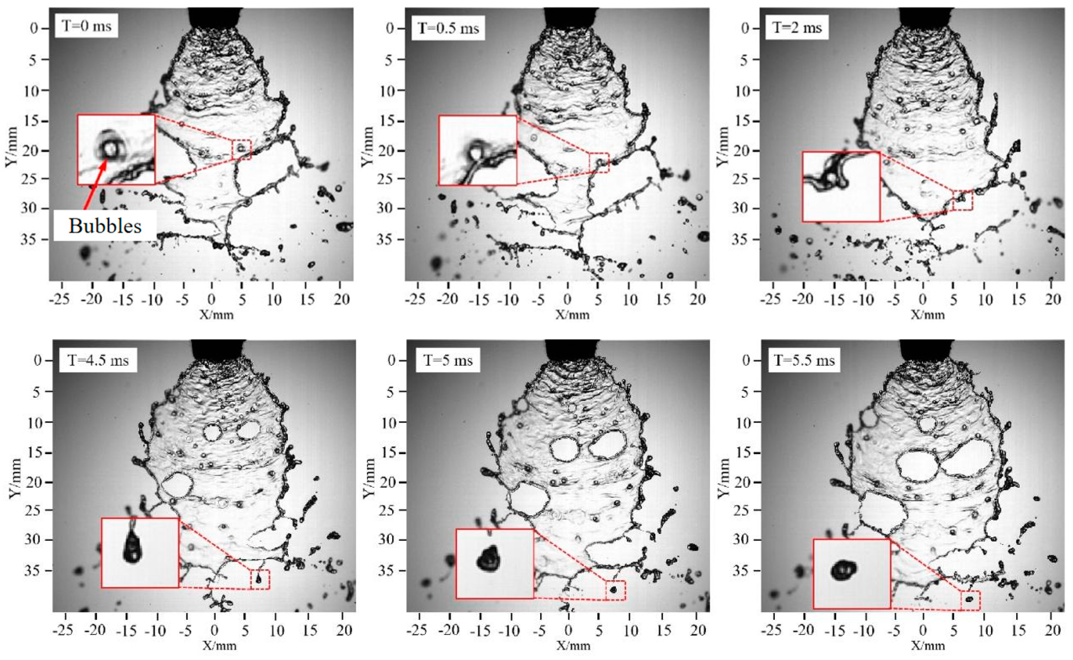
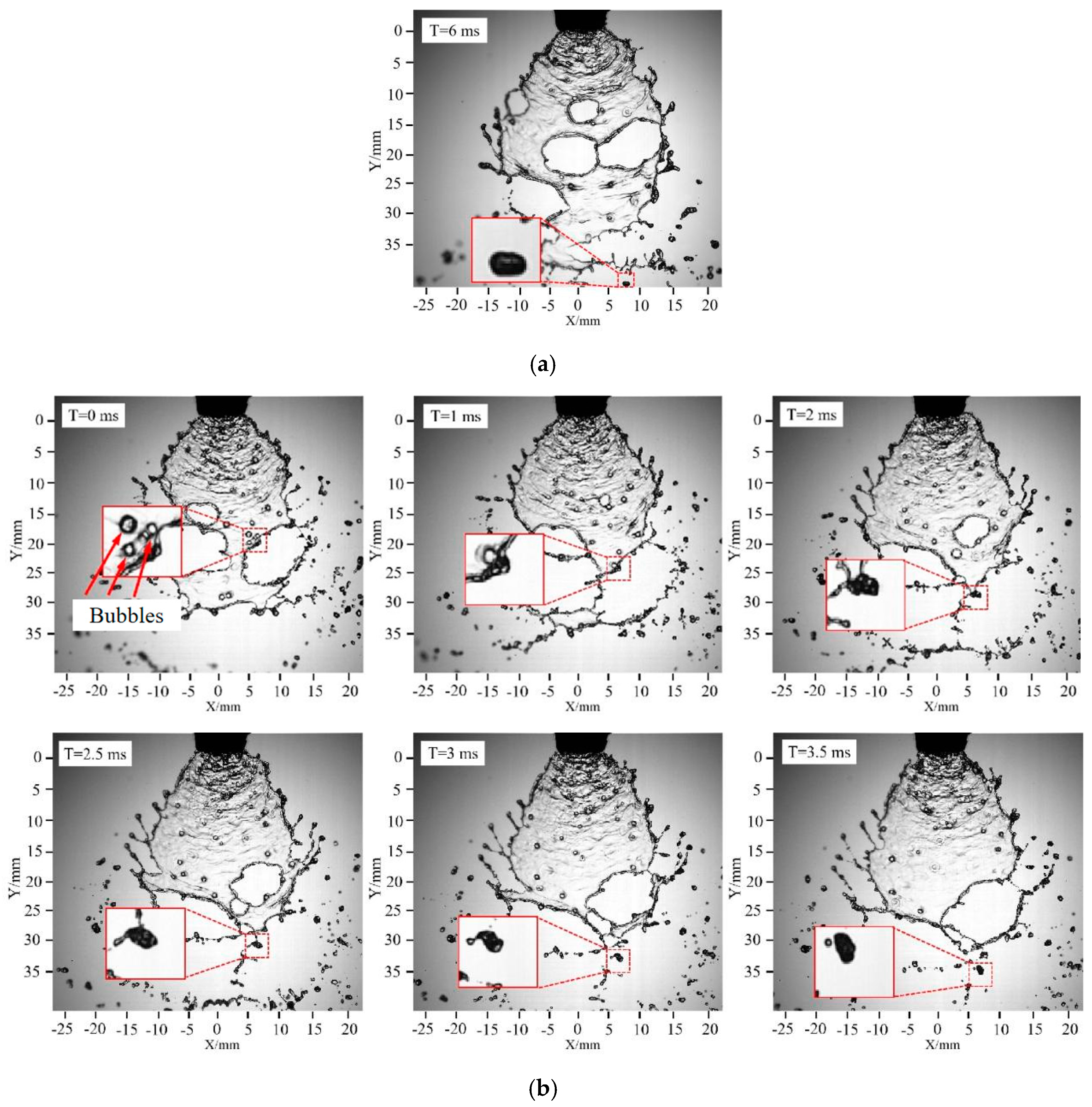
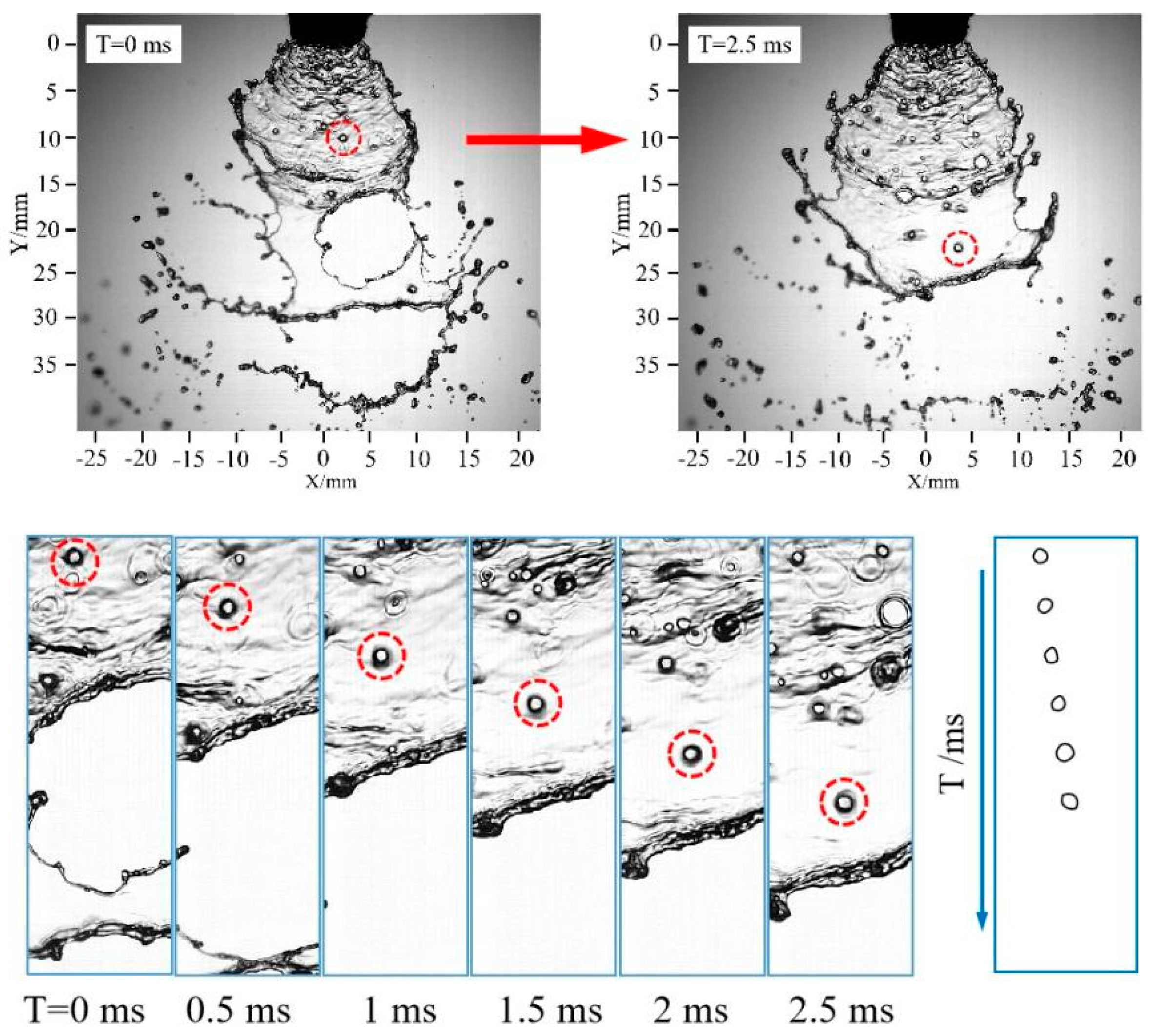
High-speed photography captured spray images, visually illustrating the evolution of bubble flow on the liquid sheet. Observed behaviors include direct perforation from bubble rupture, perforation induced by bubble rupture, ripple formation from bubble rupture, bubble coalescence leading to reduced bubble count and increased size, and the formation process of bubble-containing droplets.
(3)
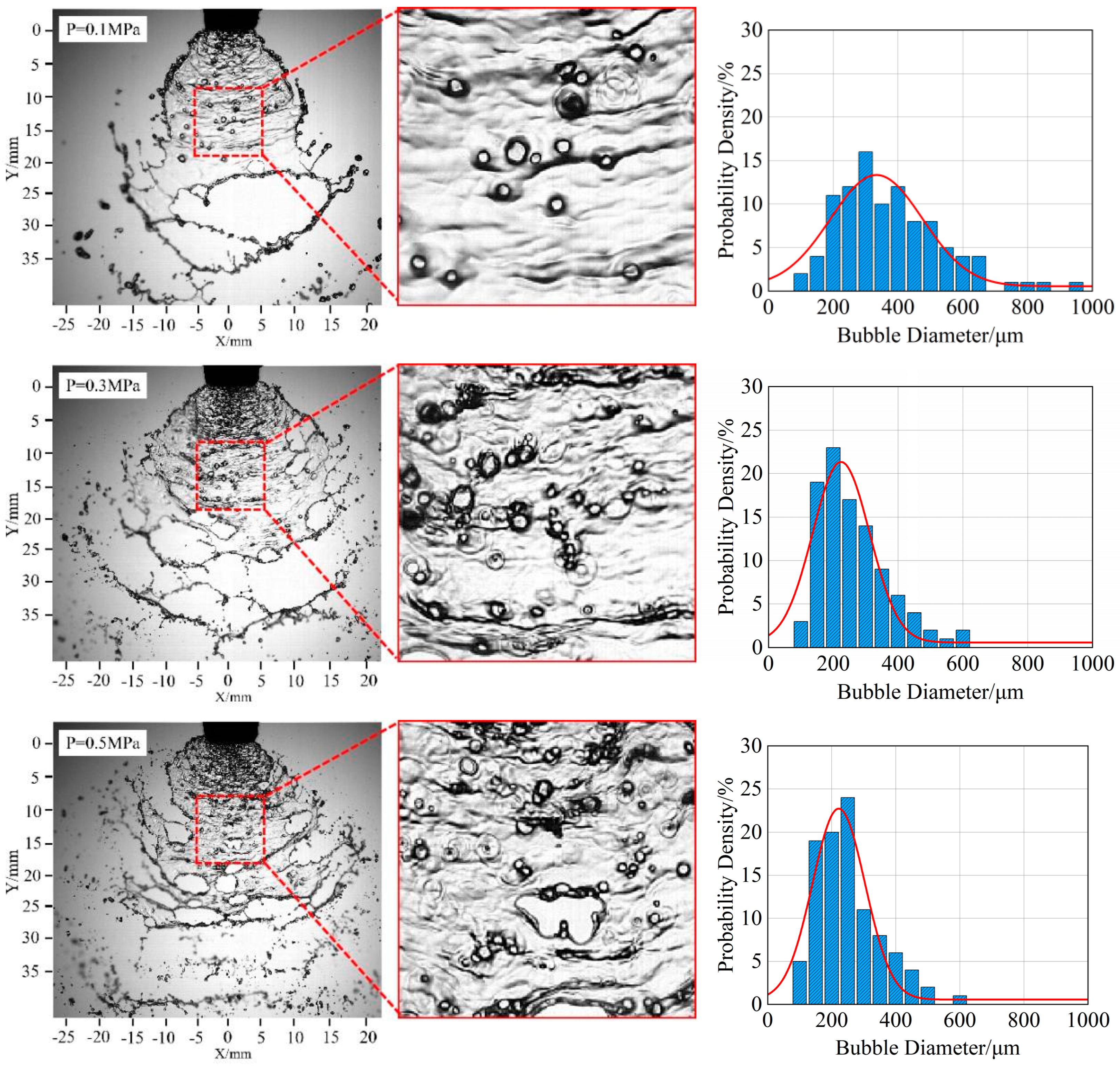
Increased spray pressure decreases the average bubble size but increases bubble count on the liquid sheet. Bubble size distributions at different spray pressures fit normal distributions. At 0.1 MPa, the bubble size distribution is widest with the fewest small bubbles; at 0.5 MPa, it narrows with more small bubbles. Higher spray pressure also intensifies liquid sheet disintegration, increasing the spray angle and disintegration length. Larger nozzle models (ID120-01 to ID120-05) increase both average bubble size and count. Bubble size distributions for different nozzles also fit normal distributions. Larger nozzles result in bigger spray angles and disintegration lengths. The ID120-01 nozzle, with the smallest primary dimensions, produces the smallest spray angle and disintegration length.
(4)
The spray liquid sheet from an air-induction nozzle contains bubbles, complicating the sheet’s characteristics. This study only explores the characteristics of the spray liquid sheet from an air-induction nozzle under pure water conditions. Further research is needed on the characteristics of the spray liquid sheet from an air-induction nozzle with more complex medicinal solutions.

Author Contributions

Preparation, creation, and presentation of the published work, specifically writing the initial draft (including substantive translation), M.Y.; application of statistical methods to synthesize and analyze data, F.C.; design of methodology and project administration, C.G.; writing—review and editing and funding acquisition, C.K. All authors have read and agreed to the published version of the manuscript.

Funding

This research was funded by the National Natural Science Foundation of China (Nos. 51905220, 52311540154), the Natural Science Foundation of Jiangsu Province, China (No. BK20231325), and a project funded by the Priority Academic Program Development of Jiangsu Higher Education Institutions (No. PAPD-2023-87).

Data Availability Statement

Data will be made available on request.

Acknowledgments

The authors thank the College of Agricultural Engineering of Jiangsu University for the experimental equipment.

Conflicts of Interest

The authors declare no conflicts of interest.

References

  1. Ma, J.; Liu, K.; Dong, X.; Huang, X.; Ahmad, F.; Qiu, B. Force and motion behaviour of crop leaves during spraying. Biosyst. Eng. 2023, 235, 83–99. [Google Scholar] [CrossRef]
  2. Qin, W.-C.; Qiu, B.-J.; Xue, X.-Y.; Chen, C.; Xu, Z.-F.; Zhou, Q.-Q. Droplet deposition and control effect of insecticides sprayed with an unmanned aerial vehicle against plant hoppers. Crop Prot. 2016, 85, 79–88. [Google Scholar] [CrossRef]
  3. Shen, Y.; Zhu, H.; Liu, H.; Chen, Y.; Ozkan, E. Development of a Laser-Guided, Embedded-Computer-Controlled, Air-Assisted Precision Sprayer. Trans. Asabe 2017, 60, 1827–1838. [Google Scholar] [CrossRef]
  4. Ahmad, F.; Zhang, S.; Qiu, B.; Ma, J.; Xin, H.; Qiu, W.; Ahmed, S.; Chandio, F.A.; Khaliq, A. Comparison of Water Sensitive Paper and Glass Strip Sampling Approaches to Access Spray Deposit by UAV Sprayers. Agronomy 2022, 12, 1302. [Google Scholar] [CrossRef]
  5. Li, J.; Nie, Z.; Chen, Y.; Ge, D.; Li, M. Development of Boom Posture Adjustment and Control System for Wide Spray Boom. Agriculture 2023, 13, 2162. [Google Scholar] [CrossRef]
  6. Zhang, C.; Zhai, C.; Zhang, M.; Zhang, C.; Zou, W.; Zhao, C. Staggered-Phase Spray Control: A Method for Eliminating the Inhomogeneity of Deposition in Low-Frequency Pulse-Width Modulation (PWM) Variable Spray. Agriculture 2024, 14, 465. [Google Scholar] [CrossRef]
  7. Shi, Q.; Mao, H.; Guan, X. Numerical Simulation and Experimental Verification of the Deposition Concentration of an Unmanned Aerial Vehicle. Appl. Eng. Agric. 2019, 35, 367–376. [Google Scholar] [CrossRef]
  8. Ferguson, J.C.; Chechetto, R.G.; Adkins, S.W.; Hewitt, A.J.; Chauhan, B.S.; Kruger, G.R.; O’Donnell, C.C. Effect of spray droplet size on herbicide efficacy on four winter annual grasses. Crop Prot. 2018, 112, 118–124. [Google Scholar] [CrossRef]
  9. Liao, J.; Hewitt, A.J.; Wang, P.; Luo, X.; Zang, Y.; Zhou, Z.; Lan, Y.; O’Donnell, C. Development of droplet characteristics prediction models for air induction nozzles based on wind tunnel tests. Int. J. Agric. Biol. Eng. 2019, 12, 1–6. [Google Scholar] [CrossRef]
  10. Liao, J.; Luo, X.; Wang, P.; Zhou, Z.; O’Donnell, C.C.; Zang, Y.; Hewitt, A.J. Analysis of the Influence of Different Parameters on Droplet Characteristics and Droplet Size Classification Categories for Air Induction Nozzle. Agronomy 2020, 10, 256. [Google Scholar] [CrossRef]
  11. Wang, C.; Zeng, A.; He, X.; Song, J.; Herbst, A.; Gao, W. Spray drift characteristics test of unmanned aerial vehicle spray unit under wind tunnel conditions. Int. J. Agric. Biol. Eng. 2020, 13, 13–21. [Google Scholar] [CrossRef]
  12. Gong, C.; Li, D.; Yan, S.; Kang, C.; Ding, K. Relation between bubble behaviors in spray sheet and bubbly flow inside an air-induction fan nozzle: A visualization study. Phys. Fluids 2024, 36, 103362. [Google Scholar] [CrossRef]
  13. Abdelmotalib, H.M.; Dafsari, R.A.; Seung-Hwa, Y.; Lee, J. Computational study of internal flow characteristics of the air induction nozzle. Int. J. Mech. Sci. 2021, 204, 106578. [Google Scholar] [CrossRef]
  14. Butts, T.R.; Luck, J.D.; Fritz, B.K.; Hoffmann, W.C.; Kruger, G.R. Evaluation of spray pattern uniformity using three unique analyses as impacted by nozzle, pressure, and pulse-width modulation duty cycle. Pest Manag. Sci. 2019, 75, 1875–1886. [Google Scholar] [CrossRef] [PubMed]
  15. Post, S.L.; Hewitt, A.J. Flat-Fan Spray Atomization Model. Trans. Asabe 2018, 61, 1249–1256. [Google Scholar] [CrossRef]
  16. Post, S.L. Drift of Droplets from Air-Induction Nozzles. Trans. Asabe 2019, 62, 1683–1687. [Google Scholar] [CrossRef]
  17. Dafsari, R.A.; Yu, S.; Choi, Y.; Lee, J. Effect of geometrical parameters of air-induction nozzles on droplet characteristics and behaviour. Biosyst. Eng. 2021, 209, 14–29. [Google Scholar] [CrossRef]
  18. McArtney, S.J.; Obermiller, J.D. Comparative performance of air-induction and conventional nozzles on an axial fan sprayer in medium density apple orchards. Horttechnology 2008, 18, 365–371. [Google Scholar] [CrossRef]
  19. Vallet, A.; Tinet, C. Characteristics of droplets from single and twin jet air induction nozzles: A preliminary investigation. Crop Prot. 2013, 48, 63–68. [Google Scholar] [CrossRef]
  20. Cryer, S.A.; Altieri, A.L. Role of large inhomogeneities in initiating liquid sheet breakup in agricultural atomisation. Biosyst. Eng. 2017, 163, 103–115. [Google Scholar] [CrossRef]
  21. Cryer, S.A.; Altieri, A.L.; Schmucker, A.L.; Day, K.M. Minimising atomisation drift potential by exploring the break-up of liquid sheets using multiphase methylated soybean and silicon oil emulsions. Biosyst. Eng. 2021, 202, 142–151. [Google Scholar] [CrossRef]
  22. Miller, P.C.H.; Ellis, M.C.B. Effects of formulation on spray nozzle performance for applications from ground-based boom sprayers. Crop Prot. 2000, 19, 609–615. [Google Scholar] [CrossRef]
  23. Altieri, A.L.; Cryer, S.A. Break-up of sprayed emulsions from flat-fan nozzles using a hole kinematics model. Biosyst. Eng. 2018, 169, 104–114. [Google Scholar] [CrossRef]
  24. Vernay, C. Destabilisation of Liquid Sheets of Dilute Emulsions; Université Montpellier: Montpellier, France, 2015. [Google Scholar]
  25. Chen, G.; Dongyang, L.; Can, K. Visualisation of the evolution of bubbles in the spray sheet discharged from the air-induction nozzle. Pest Manag. Sci. 2022, 78, 1850–1860. [Google Scholar]
  26. Hu, J.; Liu, C.; Wang, Z.; Li, Y.; Song, J.; Liu, Y.; Chu, X. Motion model for describing the quantity of air in droplets through changing the structure of air induction nozzle. Int. J. Agric. Biol. Eng. 2021, 14, 35–40. [Google Scholar] [CrossRef]
  27. Brackbill, J.U.; Kothe, D.B.; Zemach, C. A continuum method for modeling surface tension. J. Comput. Phys. 1992, 100, 335–354. [Google Scholar] [CrossRef]
  28. Duangsuwan, W.; Tuzun, U.; Sermon, P.A. The Dynamics of Single Air Bubbles and Alcohol Drops in Sunflower Oil at Various Temperatures. Aiche J. 2011, 57, 897–910. [Google Scholar] [CrossRef]
  29. Glover, G.M.C.; Generalis, S.C. The modelling of buoyancy driven flow in bubble columns. Chem. Eng. Process.-Process Intensif. 2004, 43, 101–115. [Google Scholar] [CrossRef]
  30. Ghosh, P. A comparative study of the film-drainage models for coalescence of drops and bubbles at flat interface. Chem. Eng. Technol. 2004, 27, 1200–1205. [Google Scholar] [CrossRef]
  31. Harris, P.J. An investigation into the use of the boundary integral method to model the motion of a single gas or vapour bubble in a liquid. Eng. Anal. Bound. Elem. 2004, 28, 325–332. [Google Scholar] [CrossRef]
  32. Ohta, M.; Imura, T.; Yoshida, Y.; Sussman, M. A computational study of the effect of initial bubble conditions on the motion of a gas bubble rising in viscous liquids. Int. J. Multiph. Flow 2005, 31, 223–237. [Google Scholar] [CrossRef]
Figure 1. Schematic diagram of spray equipment.
Agronomy 15 01270 g001
Figure 2. Experiment devices.
Agronomy 15 01270 g002
Figure 3. Structure diagram of air-induction nozzle and flat-fan nozzle: (a) actual diagram of the nozzle; (b) sectional view of air-induction nozzle; (c) outlet of air-induction nozzle.
Agronomy 15 01270 g003
Figure 4. Measurement of liquid sheet.
Agronomy 15 01270 g004
Figure 5. Measurement of spray angle and breakup length.
Agronomy 15 01270 g005
Figure 6. The difference between perforation and bubble in the liquid sheet. The bubbles are indicated with blue arrows, while the perforations are indicated with red arrows.
Agronomy 15 01270 g006
Figure 7. Comparison of liquid sheet disintegration characteristics under different spray conditions: (a) image of the liquid sheet in its natural state; (b) image of the liquid sheet with the air inlet blocked; (c) image of the liquid sheet from a standard flat-fan spray; (d) liquid sheet spray angles under different spray conditions; (e) lengths of liquid sheet disintegration under different spray conditions.
Agronomy 15 01270 g007aAgronomy 15 01270 g007b
Figure 8. Bubble disintegration directly forms perforation.
Agronomy 15 01270 g008aAgronomy 15 01270 g008b
Figure 9. Bubble disintegration induces the formation of a perforation.
Agronomy 15 01270 g009
Figure 10. Bubble disintegration directly forms ripples.
Agronomy 15 01270 g010
Figure 11. Multiple bubbles disintegrating.
Agronomy 15 01270 g011
Figure 12. Schematic diagram of perforation produced by bubble disintegration: (a) the large bubble bursts; (b) the small bubble bursts.
Agronomy 15 01270 g012aAgronomy 15 01270 g012b
Figure 13. Bubbles coalescence: (a) coalescence of two bubbles; (b) coalescence of multiple bubbles.
Agronomy 15 01270 g013aAgronomy 15 01270 g013b
Figure 14. Schematic diagram of bubble coalescence.
Agronomy 15 01270 g014
Figure 15. Evolution process of bubble entering droplet: (a) single bubble entering a droplet; (b) multiple bubbles entering a droplet.
Agronomy 15 01270 g015aAgronomy 15 01270 g015b
Figure 16. Image of bubble evolution and trajectory on liquid sheet.
Agronomy 15 01270 g016
Figure 17. Image and size distribution of bubbles on the spray liquid sheet under different spray pressures.
Agronomy 15 01270 g017
Figure 18. Spray angle and disintegration length of the spray liquid sheet under different spray pressures.
Agronomy 15 01270 g018
Figure 19. Image and size distribution of bubbles on the spray liquid sheet under different nozzle models.
Agronomy 15 01270 g019
Figure 20. Spray angle and disintegration length of the spray liquid sheet under different nozzle models.
Agronomy 15 01270 g020
Table 1. Main parameters of air-induction nozzle.
Nozzle TypeLiquid Inlet Diameter
Dl/mm
Air Inlet Diameter
Da/mm
V-Notch
Angle
a
Long Axis Diameter of Nozzle Outlet
DL/mm
Short Axis Diameter of Nozzle Outlet
DS/mm
LU120-03--162.470.44
ID120-010.721.41262.100.50
ID120-031.291.54312.980.99
ID120-051.731.96344.121.19
Disclaimer/Publisher’s Note: The statements, opinions and data contained in all publications are solely those of the individual author(s) and contributor(s) and not of MDPI and/or the editor(s). MDPI and/or the editor(s) disclaim responsibility for any injury to people or property resulting from any ideas, methods, instructions or products referred to in the content.

