Abstract
The planter plate is the most important component of the pneumatic hill-drop seed metering system for rapeseed. The structural parameters of the planter plate are the primary determinants of rape planting. The key structural and operational parameters, such as the layout of the suction hole, its diameter, and its shape, were determined through theoretical analysis. Fluent is used to simulate the flow field of various types of suction holes, and the effect of suction hole shape on the change in the flow field of the suction chamber shell is analyzed. Under the same boundary conditions, the results indicate that the maximum velocity of the end face of the horn hole and the average pressure of the section are the highest. Using a high-speed camera, the effects of suction hole diameter and shape on seed filling performance were studied, and the results of Fluent simulation analysis were validated. The optimal seed metering device operating parameters were as follows: planter plate speed of 30–70 r/min and negative pressure of −2.5–−1.5 kPa. The influence of working negative pressure and the rotational speed of the planter plate on seed arrangement performance was studied within the optimal operating parameter range. In order to improve the performance of rational close planting in the seed planter, the multi-objective optimization design of working parameters and the verification test were also conducted. The results showed that with the best combination of working parameters, the empty broadcast rate does not go above 3%, the hole number qualified rate does not go below 96%, and the difference between them and the theoretical optimization result does not go above 5.5%.
1. Introduction
Precision sowing technology for rapeseed is one of the most important means of achieving cost savings and efficiency gains through mechanization and large-scale planting, as well as the central and most difficult aspect of rapeseed mechanization research as a whole. The characteristics of rapeseed seeds are small particle size, high sphericity, and good fluidity. However, its thin skin and high oil content, which are prone to damage and blockage phenomena, impact the uniformity of the seed row, which is the difficulty and key to precision seed row planting [1]. The seed metering device is the key component of precision sowing in rapeseed, and can be divided into mechanical and pneumatic types. The pneumatic seed metering device adsorbed the seeds on the planter plate under negative pressure in the seed filling area, transported the seeds to the unloading area by seed circling, and planted the seeds using the seeds’ own gravity and positive pressure. This method has the benefits of high adaptability to seeds, little damage, etc. It is used frequently because it solves the technical problem of how to plant single seeds with small particle sizes, such as rape [2,3,4]. With the domestic and international promotion and development of conservation tillage in recent years, the conservation tillage requirement of full straw return has had a significant effect on crop sowing, particularly the sowing and growth of rape [5]. It was discovered that rational close planting of rapeseed was an important way to increase its yield and fertilizer utilization efficiency, as well as reduce the effect of total straw returning on rapeseed sowing [6].
Scholars at home and abroad have conducted a lot of research from many different points of view on pneumatic seed metering devices for rapeseed to meet the demand for dense planting. Yin W.Q. et al. [7] utilized a combination of pneumatic and trough wheels to perform two-stage precision sowing of vegetables and conducted a bench test; the results satisfied the sowing index requirements. Liao Q.X. et al. [8] utilized pneumatic centralized seed metering devices for precise seeding of small-particle-sized crops, and single seed metering devices for precise single-seed seeding of small-particle-sized vegetable seeds. Li J.H. et al. [9] built and improved the empirical model of high sphericity seed suction through a self-designed suction measuring device, and studied the relationship between the resistance model and the suction model. Li Z.D. et al. [10] increased the population disturbance intensity by adding grooves and seed-stirring teeth to the traditional planter plate, thereby reducing the seed leakage rate during the high-speed seeding process. Xin J. et al. [11] designed a small electric precision planter for vegetable seeds that could quickly adjust row spacing and sowing depth to meet the needs of agricultural planting. Cheng X.P. et al. [12] utilized CFD technology to analyze the flow field, study the impact of various suction hole apertures on the change of air flow, and determine the aperture range of the suction hole of the seeding device. Li Z.H. et al. [13] utilized CFD to study the internal flow field of the air-stream distributive metering device, optimized the structure of the air-stream distributive metering device, and finally eliminated vortex-caused seed detention. Lei X.L. et al. [14,15] used CFD technology to study the internal flow field of the centralized air-assisted seed-metering machines for rapeseed and wheat, and improved the working performance of the centralized air-assisted seed-metering machines for rapeseed and wheat through structural optimization. Ibrahim E.J. et al. [16] designed a pneumatic seed metering device with one device and four rows, and experimented with its performance at various rotation speeds and negative pressures. The results indicated that the sowing quantity of each row varied little, thereby satisfying the agronomic requirements. Gaikward B.B. et al. [17] designed a pneumatic seed metering device with a plunger tray for sowing vegetables, which reduced the original price by 15.27%. Yazgi A. et al. [18] used cotton and corn seeds as research objects, conducted experiments on the influence of the operation speed of the seeder and the number of disc-type holes on the performance of the disc air-suction type seed planter, and discovered the optimal number of disc-type holes for the two crops. To address the issue of the instability of the airflow field during the filling process of the air-suction seed metering device, Özmerzi A et al. [19] described the capture mechanism of seeds based on the fundamental principles of fluid mechanics and aerodynamics by developing a nomograph, which effectively improved the stability of the seed absorption process of the air-suction seed metering device. Andrii Y. et al. [20] utilized high-speed camera technology to study the distributor of a pneumatic seeder, analyzed and optimized the structural parameters of the distributor, and enhanced the stability of high-speed seeding performance.
Although many scholars have performed a lot of work on the pneumatic seed arrangement device for reasonable dense planting, mainly by improving the rotation speed of the planter plate and working with negative pressure to meet the requirements of dense planting, in field work, the wind pressure is provided by the air pump, which is driven by the power output shaft of the tractor. During the seeding process, the seeding machine does not move at a constant speed, and it is difficult for the air pump to maintain a constant high pressure. The increase in the rotation speed of the planter plate will lead to a deterioration in the filling performance and affect the uniformity of seeding. On the basis of this research, this paper proposes to solve this problem by increasing the number of suction holes to achieve low-speed, dense planting. The number, diameter, and spacing of suction holes on the seed plate were studied by theoretical analysis. CFD was used to simulate the flow field of different orifice patterns, and the results show that the horn-shaped suction hole is the best suction hole. The influence of the structure parameters and operating parameters of the seed plate on the seed filling performance was studied using high-speed camera technology, and the structure parameters of the planter plate were optimized by the contour map analysis method. Under the condition of optimal structure parameters for the planter plate, response surface analysis was used to study the variation rule of seed metering device performance with working parameters, and the optimal working range of the seed metering device was determined, which improved the performance of the precision seed metering device. It provides a theoretical foundation for the design of a precision seed apparatus with agronomic combinations and precision dense planting for rapeseed.
2. Structure and Working Principle of the Seed Metering Device
2.1. Structure of the Seed Metering Device
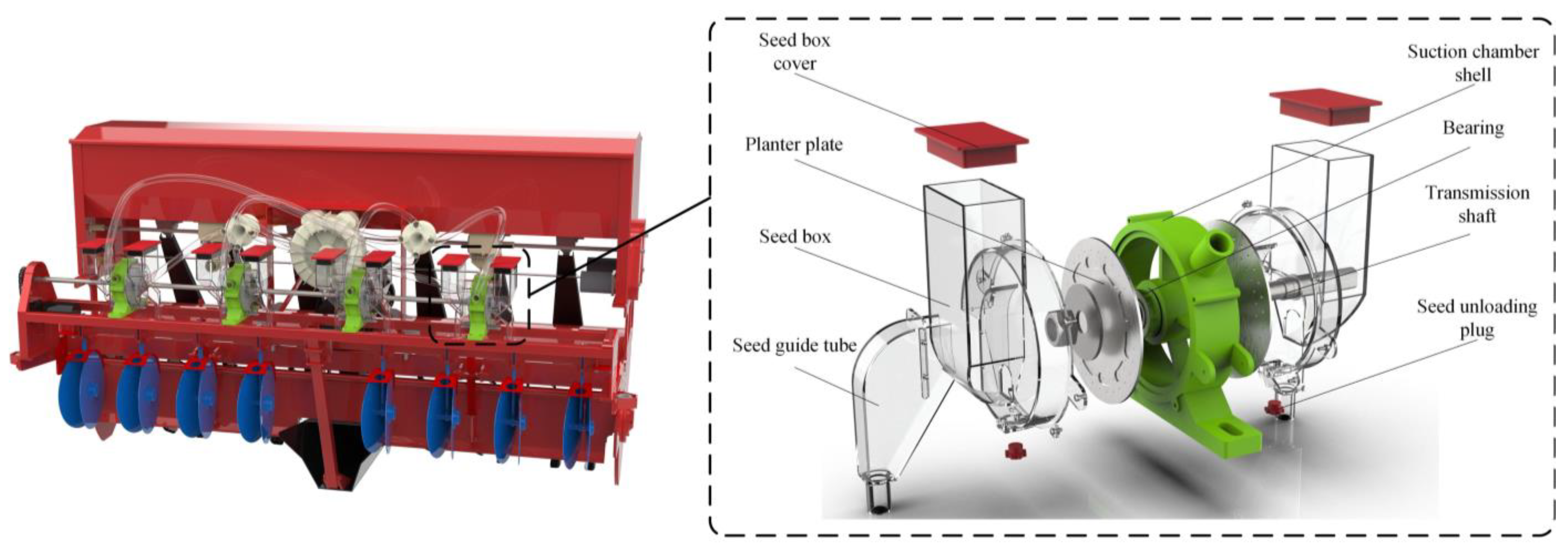
As illustrated in Figure 1, the pneumatic hill-drop seed metering device for rapeseed designed in this paper consists primarily of a seed guide tube, seed unloading plug, seed box, seed box cover, planter plate, suction chamber shell, transmission shaft, etc. The structure of the planter plate has a direct effect on the performance of the seed arrangement device, and it is the device’s central component [21,22].

Figure 1.
View of the seed metering device in fragments.
2.2. Working Principle of the Seed Metering Devic
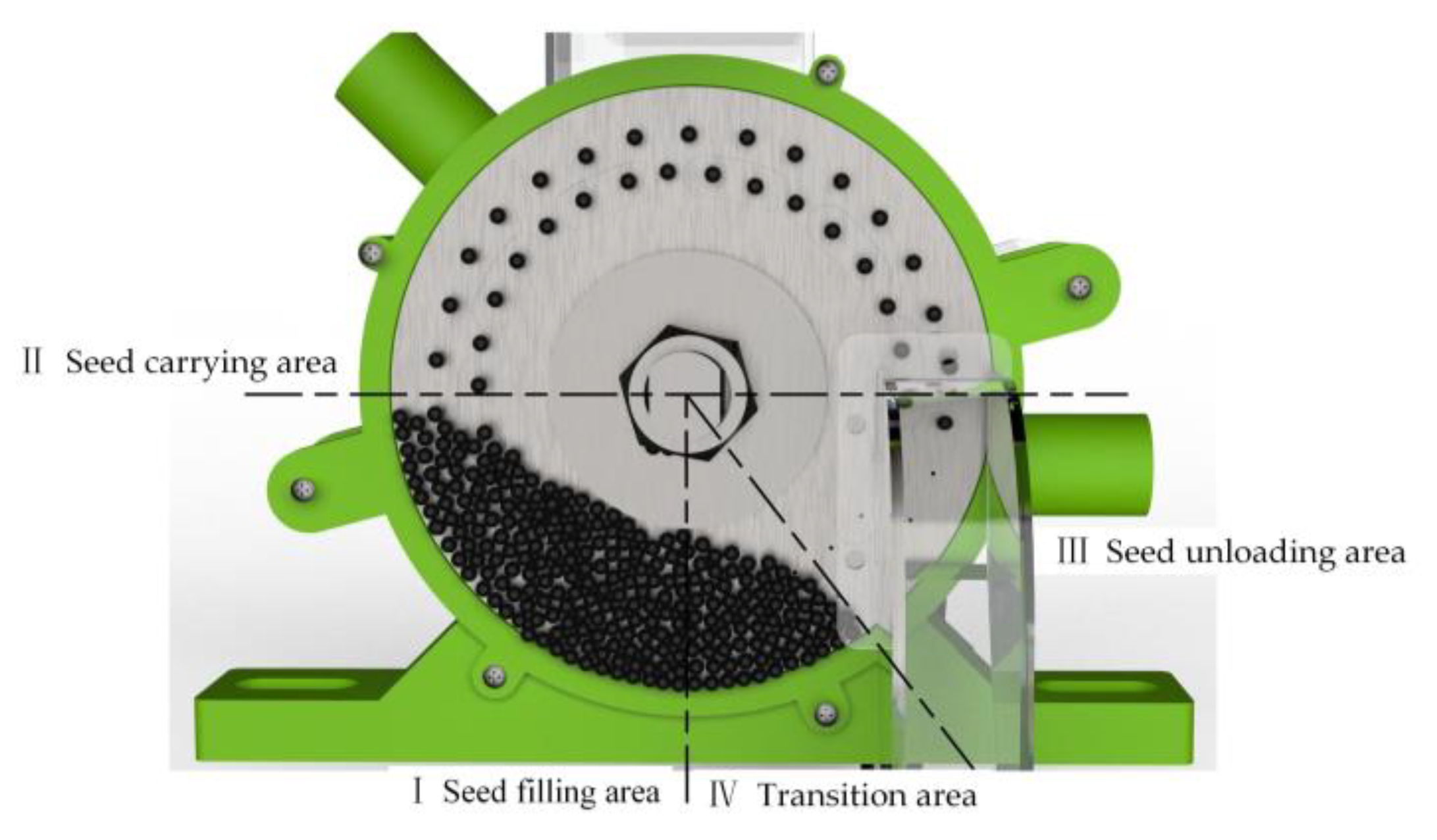
As shown in Figure 2, the seed metering device was subdivided into the seed filling area I, the seed carrying area II, the seed unloading area III, and the transition area IV based on their respective functions and operation sequences. First, the seed box is filled with rapeseed. Due to the force of gravity, the seeds fall into the filling area. The metering rotation of the stepper motor driver is counter-clockwise. Under the influence of negative pressure, this type of groove and tooth structure can break the accumulation of seeds and allow the seeds to achieve precise adsorption on the suction hole on the planter plate. When the rotating hopper in carrying area II and the suction hole on the planter plate reach unloading area III, gravity and positive pressure separate the seeds from the suction hole, and they then fall into the seed guide tube to complete the seeding process. After the seeds are unloaded, the suction hole goes straight to transition zone IV to get ready for the next step, which is seed filling.

Figure 2.
Diagrammatic representation of the working area division of the seed metering device.
3. Materials and Methods
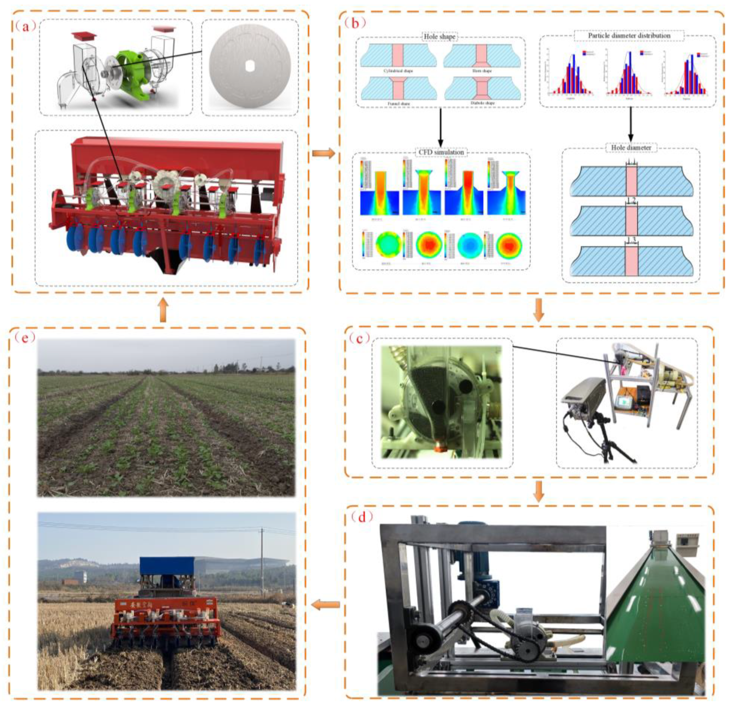
The seed filling link is the fundamental link of the rapeseed seed metering device, and the performance of the seed filling link of the seed-arranging device will directly affect the seed-arranging effect [23]. In this study, CFD numerical simulation technology and high-speed camera technology were used to optimize the structure and operation parameters of the planter plate, improve the filling performance, and improve the dense planting performance of the rapeseed seed metering device, respectively. Figure 3 depicts the technical route studied in this paper.

Figure 3.
Roadmap for Research and Technology. (a) Structure of a seed metering device; (b) Simulation and design of type hole structures; (c) Test of the performance of seed filling; (d) Test of the performance of the seed arrangement; (e) Field test and emergence condition.
3.1. Key Parameter Design of the Planter Plate
3.1.1. Diameter of Planter Plate Design
The planter plate is essential for accurate sowing of rapeseed components. Its diameter directly influences the quantity of holes [24]. According to the study [25], the larger the diameter of the seed plate, the larger the number of suction holes that can be accommodated. Rotating can carry more seeds for a week, but an increase in the diameter of the planter plate results in a larger seed metering device, so it is essential to select the appropriate plate diameter. Formula (1) can be derived from the relationship between the speed of the seed disk and the filling time:
where t is the time (s) the suction hole takes to stay in the seed filling area; l is the length (m) of the seed filling area’s Arc; vp is the linear velocity (m/s) of the planter plate; α is the seed-filling angle (rad); dp is the diameter (m) of the planter plate; n is the rotation speed (r/min) of the planter plate; while h is the radial distance (m) between the center of the suction hole and the edge of the planter plate.
Formula (2) can be deduced from Formula (1):
According to Formula (2), the filling time was only related to the filling angle and the speed of the planter plate, and increasing the planter plate’s diameter did not increase the residence time of the suction hole in the filling area. The diameter of the planter plate of the current pneumatic seed metering device ranges between 80 and 260 mm. According to the seed arranger’s overall design, the diameter dp of the seed plate is 140 mm, and the material is aluminum alloy.
3.1.2. Type of Hole Arrangement Form and Double Row Hole Spacing Design
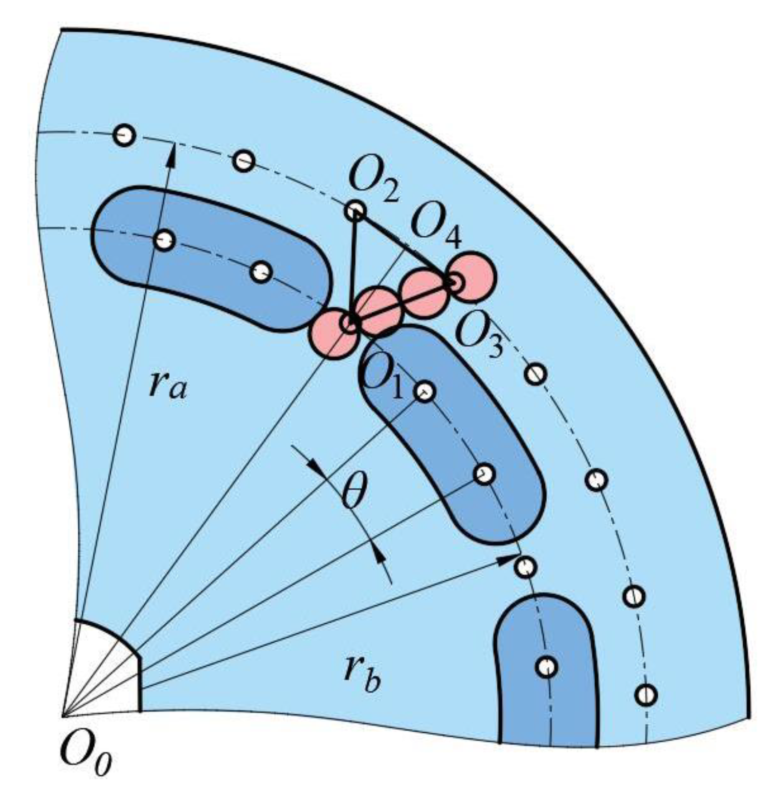
According to the agronomic requirements of rapeseed sowing under the full amount of returning straw and the structural characteristics of the pneumatic hill-drop seed measuring device for rapeseed, the suction hole arrangement is designed as depicted in Figure 4. The center spacing of inner and outer suction holes had a significant impact on the filling and transporting of seeds. Excessive center spacing caused the inner suction hole’s position to deviate from the population center, and the community was unable to better cover the suction hole during the seed filling process, resulting in a decline in the inner suction hole’s seed filling performance. If the space in the middle is not big enough, the seeds on both sides of the suction hole will bump into each other while the seeds are being carried.

Figure 4.
A schematic diagram of the suction hole arrangement.
According to the above geometric relations, ΔO1O2O3 is an isosceles triangle, point O4 is the midpoint of segment O2O3. Formula (3) can be deduced.
where θ is the Angle between two adjacent suction holes.
The distance between two double rows of holes must satisfy the following conditions, according to Formula (3).
From (3) and (4), it can be concluded that lO1O4 must meet the Formula (5) [26]:
According to the suction hole diameter formula [27], d = (0.64–0.66) × b, where d is the average seed diameter (mm); rb = 50 mm; θ = 12°.
It can be seen from the equation that the spacing between two rows of holes depends on the average seed particle size b, and there is a positive correlation between them. Taking Huayouza 62 as an example, the average particle size of particles measured was 1.989 mm. After calculation, lO1O4 > 9.65 mm. The spacing between two rows of holes was selected as 10 mm and r = 60 mm based on the preliminary test and actual situation.
3.1.3. Suction Hole Number Design
When the unit’s operation speed and seed spacing are held constant, the greater the number of holes on the planter plate, the lower the required rotation speed of the planter plate, and the lower the linear velocity of the seed on the suction hole. Therefore, the number of suction holes on the planter plate should be as large as possible when conditions permit. The operation speed of the seeder unit, va ≤ 10.8 km/h, and the rotational speed of the planter plate, n ≤ 80 r/min, were designed based on the agronomic requirements of mechanical sowing in rapeseed fields. According to the “Agricultural Machinery Design Manual” [28], the linear speed of the suction holes is generally less than 0.2 m/s, and the reasonable seed spacing is 0.06–0.08 m. The number of suction holes on the planter plate must satisfy the Formula (6):
where n is the rotational speed (r/min) of the planter plate; vm is operation speed (km/h) of seeder unit; vw is the linear speed (m/s) of the suction holes; S is the seed spacing (m).
From the formula, 27.08 ≤ Z ≤ 38.89. To increase the number of suction holes in a reasonable manner and to simplify processing, the center angle of adjacent holes is set to an integer. This planter plate contains a total of 60 suction holes, with 30 inner suction holes and 30 outer suction holes. There is a 12-degree angle between adjacent holes.
3.1.4. The Suction Hole Shape Design
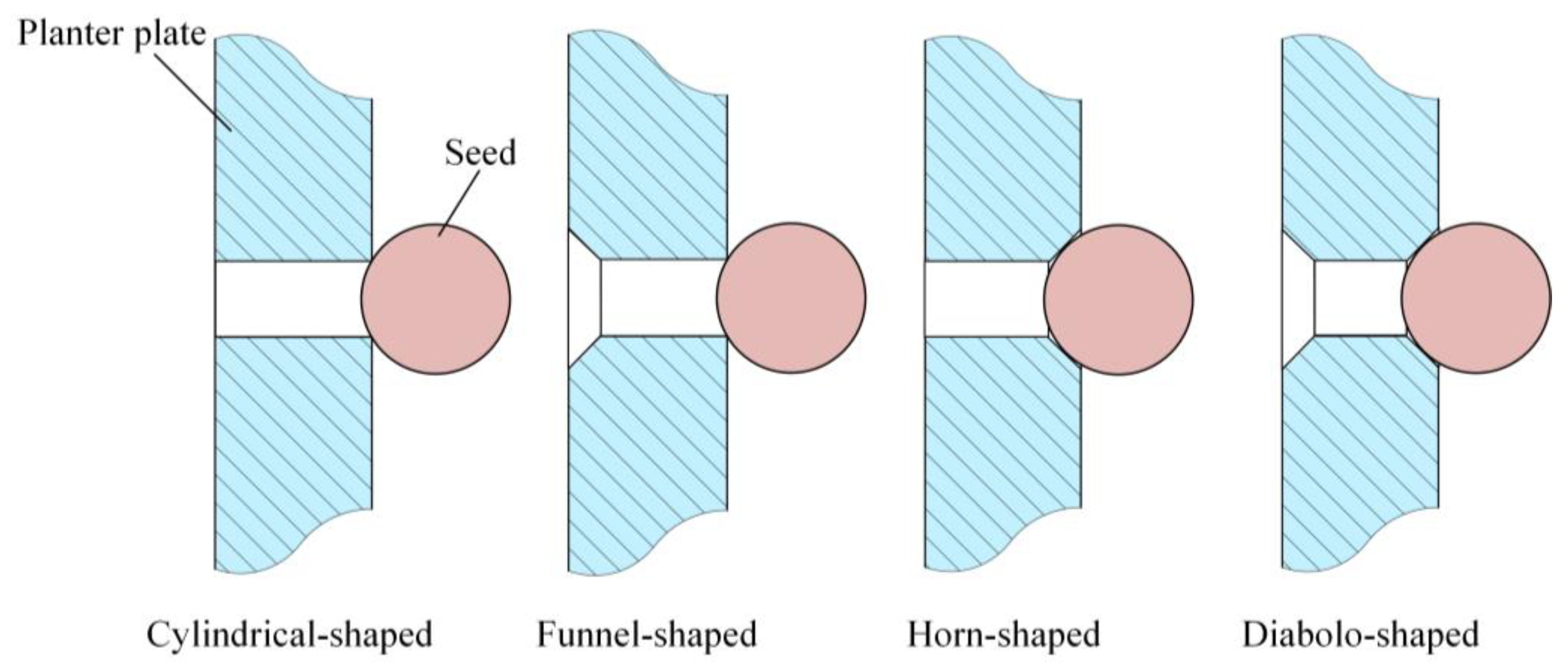
Seed filling is the fundamental part of seed arrangement, and the structure of the suction hole is the most influential factor in determining the seed filling effect [29]. When conditions are the same, the greater the negative pressure on the end face of the suction hole, the better the suction hole is at catching seeds and the more stable its adsorption. According to the theory of fluid local resistance loss [30], a change in the structure of a suction hole can affect the magnitude and direction of air velocity, resulting in an eddy current and swirl that cause local energy loss. Combining actual production and processing simultaneously, this paper presents four distinct designs for suction holes: cylindrical-shaped, funnel-shaped, horn-shaped, and diabolo-shaped, as shown in Figure 5. A suction hole comparison experiment was conducted.
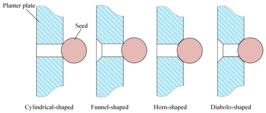
Figure 5.
Different shapes of the suction hole structure drawings.
3.2. Analysis of the Processes of Seed Filling and Seed Unloading
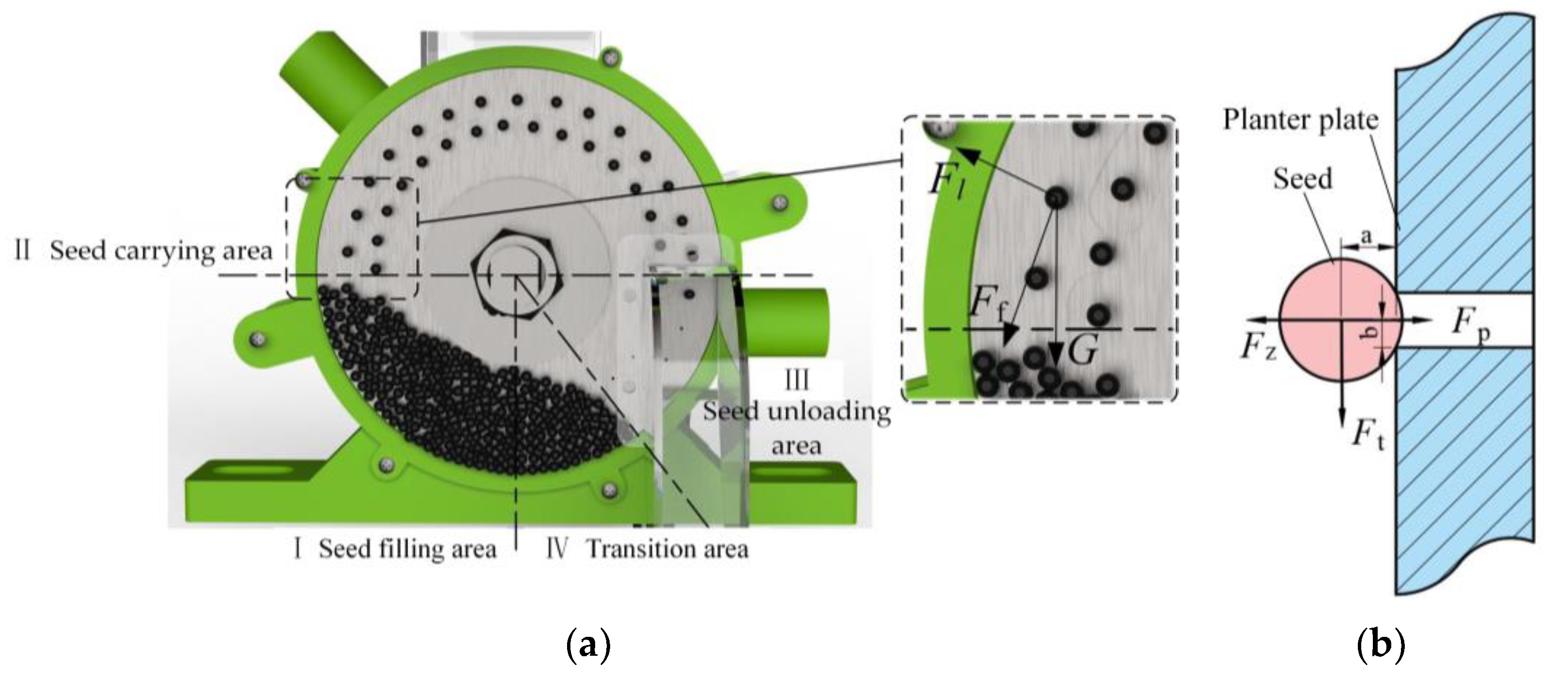
3.2.1. Analysis of the Seed Filling Process’s Kinetics
The seeds entered the filling area from the seed box under the influence of gravity and were dispersed by the planter plate’s groove tooth structure. Under the influence of negative pressure on the suction hole, the seeds were accurately adsorbed on the suction hole of the planter plate, thereby completing the seed arrangement process with the planter plate. Consequently, the suction hole played a crucial role in the precise capture of seeds. Using a single seed adsorbed by a suction hole as the research object, the seed is assumed to be a rigid body made of a uniform material, and the force analysis is depicted in Figure 6. Vibration and seed collisions are not considered. Formula (7) illustrates the following force equation that applies to seeds based on the theory of rigid body dynamics [31]:
where G is gravity (N) of seed, Fl is Centrifugal force (N) on the seed, Ff is frictional resistance (N) between seeds, Fp is the suction force (N) of the suction hole on the seed, Fz is the sum of Z-axis forces (N), Ft is the sum of the forces (N) on the xy plane, a is The distance (m) between the seed’s center of gravity and the suction hole’s end face, b is half the diameter (m) of the suction hole.

Figure 6.
Force analysis diagram of an adsorbed seed. (a) Force analysis in the xy plane; (b) Force analysis in the yz plane.
Formula (8) can be deduced from Formula (7):
The actual operation of the seed metering device will be affected by its own conditions and objective conditions such as vibration, so two parameters are introduced: the reliability coefficient of seed absorption k1 and the external condition coefficient k2 [32], where the range of values for k1 is 1.8–2.0 and the range of values for k2 is 1.6–2.0. Formula (9) can be deduced from Formula (8):
In Equation (9), Fz ≥ 0 and a ≤ R, Po has a minimum value when Fz = 0; however, Fz must be greater than 0 for the seed to adhere to the suction hole. In conjunction with Formula (9), the Formula (10) can be deduced:
According to the formula, the pressure required for successful absorption of seeds by suction holes is dependent on the seed radius R, the seed rotation angle velocity, the seed mass m, and the suction hole diameter d. Therefore, the diameter of the suction holes must correspond to the diameter of the seeds. According to a review of the relevant literature, the formula d = (0.64–0.66) r, where r is the average grain size of rapeseed seeds, can be used to calculate the diameter of medium-sized holes in pneumatic seed metering devices.
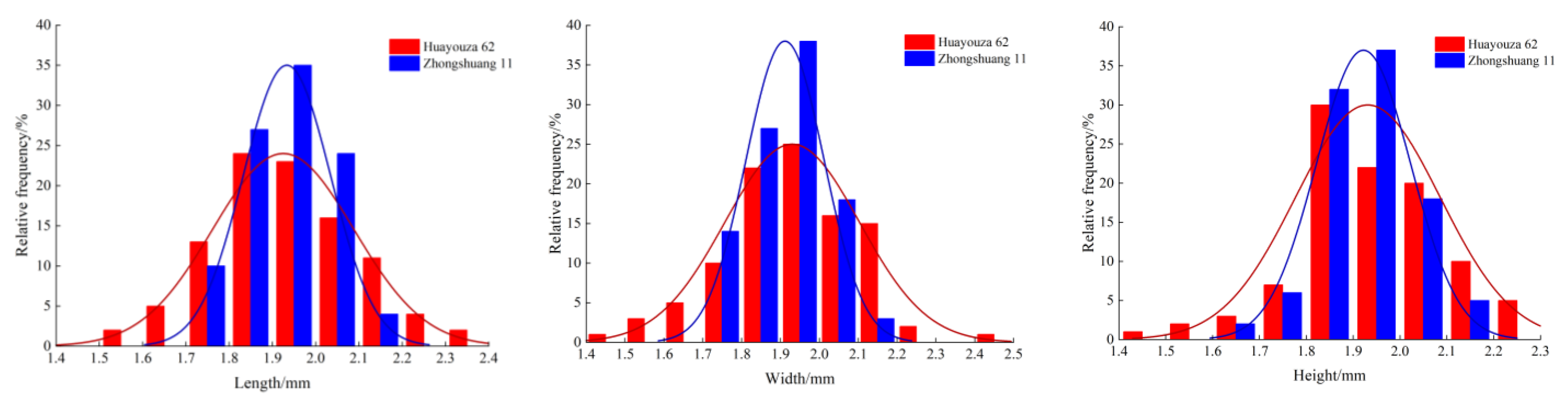
To determine the average particle size of rapeseed seeds, two representative varieties, Huayouza 62 and Zhongshuang 11, were chosen, their triaxial sizes were measured, and the frequency distribution histogram is depicted in Figure 7. Combined with existing studies, the average particle size of rapeseed seeds was determined to be (1.8–2.0) × 10−3 m. Using the formula for suction hole size, the suction hole size range is (1.15–1.32) × 10−3 m. In this study, the sizes of the suction holes were 1.1, 1.2, and 1.3 × 10⁻³ m. In practice, when the suction hole structure is determined and the interaction between seeds is disregarded, the minimum theoretical negative pressure value required for the successful adsorption of seeds by the suction hole in the process of filling seeds can be calculated using Formula 10, which yields a value of −362.53 Pa. Therefore, the pressure value during the test must be greater than −362.53 Pa.
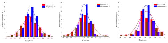
Figure 7.
Triaxial size frequency distribution histogram of rapeseed seeds.
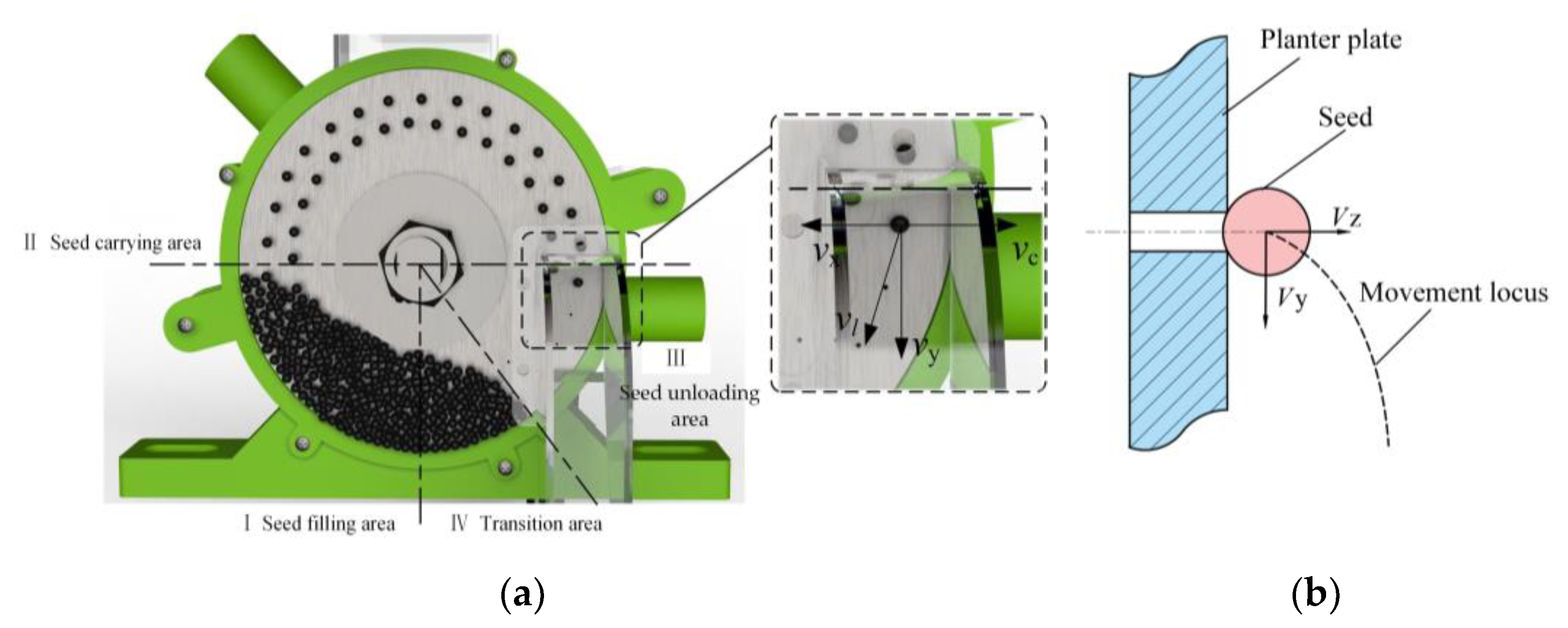
3.2.2. Analysis of the Seed Unloading Process’ Kinematics
The suction hole absorbs the seeds and transports them to the unloading area. Under the action of positive pressure, the seeds get out of the suction hole and obtain an initial velocity vz perpendicular to the planter plate surface. Prior to leaving the suction hole, the seed moves with the planter plate. After leaving the planter plate, the seed has a velocity of vl in the tangential direction along the circumference of the suction hole in a plane parallel to the planter plate. Under the influence of gravity, the vertical direction is subject to gravity’s acceleration, and the influence of air resistance on seeds is ignored. As shown in Figure 8, seed kinematic analysis is conducted in the unloading area, and the following Formula (11) was obtained:
where vx is the horizontal speed (m/s) of the seed as it leaves the planter plate, vy the is speed (m/s) of the seed as it leaves the planter plate, v′x is 2032 the fractional speed (m/s) in the X direction when the seed touches the seedbed, v′y is the fractional speed (m/s) in the Y direction when the seed touches the seedbed, v′z is the fractional speed (m/s) in the Z direction when the seed touches the seedbed, vl is the circumferential speed (m/s) of the suction hole, vc is operation speed (km/h) of seeder unit, t0 is the seeds’ departure time (s) from the planter plate, t is the time at which the seed falls, α is the angle(°) between vl and vx.

Figure 8.
Analysis of the processes seed arrangement. (a) Kinematics analysis in the xy plane; (b) Kinematics analysis in the yz plane.
Formula (12) can be deduced from Formula (11):
In the formula, the falling time t can be calculated, and the circumferential speed of the suction hole and operating speed of the seeder unit can be obtained as follows from the “Agricultural Machinery Design Manual”. In conclusion, Equation (13) is obtained as follows:
Formula (14) can be obtained by combining Formulas (11)–(13) as follows:
The fractional velocity in the vertical direction causes the seeds to rebound when they strike the seedbed. This alters the spacing between seeds. According to Equation (14), the vertical dividing speed is proportional to the speed of the planter plate, the circumference radius of the suction hole, and the height of seeding when the seeds hit the seed bed. The greater the vertical dividing speed when the seeds contact the seedbed, the more severe the impact rebound phenomenon, and the greater the variation coefficient of seed spacing. Reducing the rotation speed of the planter plate can effectively reduce the coefficient of variation of seed spacing and enhance the performance of the seed metering device while still meeting the requirements of seeding. According to the agronomic requirements of rapeseed sowing, when the actual operating speed was 1.5–2.0 m/s and the seed spacing was 0.05–0.08 m, the speed range of the planter plate was 31.25–66.7 r/min.
3.3. Simulation Model and Parameter Setting
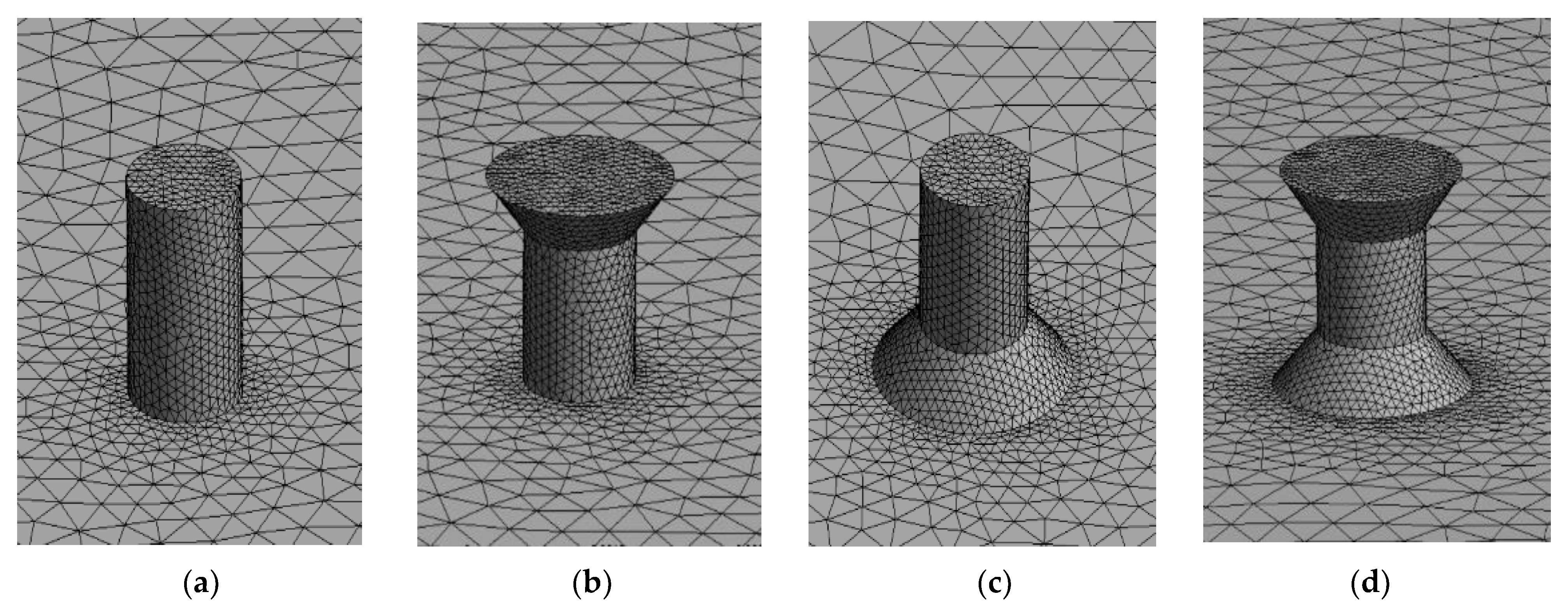
The suction surface is set to inlet, the outer end of the chamber conduit is set to outlet, the tetrahedral method was used to divide the mesh, the independence test was conducted in conjunction with the unstructured grid, and the other surfaces are set to wall with a minimum grid size of 0.001 m. To effectively capture the flow characteristics of the fluid boundary accessory, assuming that there is no slip between the fluid and solid boundaries, a boundary layer is added to the wall’s surface group. Five is the maximum number of boundary layer layers, 1.5 is the growth rate, and 0.272 is the default transition ratio. Figure 9 illustrates the subdivision of the mesh [33].
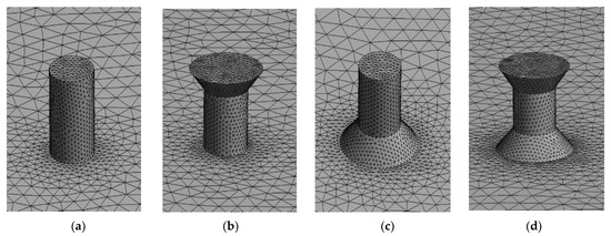
Figure 9.
Mesh division of different suction hole shapes. (a) Cylindrical-shaped suction hole; (b) Funnel-shaped suction hole; (c) Horn-shaped suction hole; (d) Diabolo-shaped suction hole.
In the Fluent setting, the K-stand turbulence model and pressure-inlet, pressure-outlet, and wall boundary conditions were selected. The inlet pressure was set to 0 p, and the outlet pressure was set to −1500 p. To comprehend the characteristics of the overall air flow field in the air chamber, an output surface is positioned 5 mm above the suction hole’s bottom surface. The simple default calculation method was adopted. The second-order scheme was used to solve the pressure equation, the second-order upwind scheme was used to solve the momentum equation, and the second-order upwind scheme was used to solve the turbulent kinetic energy and turbulent dissipation rate.
3.4. Test Materials and Equipment
3.4.1. Equipment for Testing the Performance of Seed Filling
In this experiment, the rapeseed variety Huayouza 62 with a thousand grain weight of 4.38 g and an average particle size of 1.989 mm was chosen as the test material. Figure 10 shows that the testing equipment is made up of a single row of seed filling performance test stand for small particles.
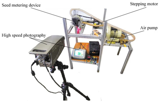
Figure 10.
Seed filling performance test stand.
3.4.2. Equipment for Testing the Performance of Seed Arrangement
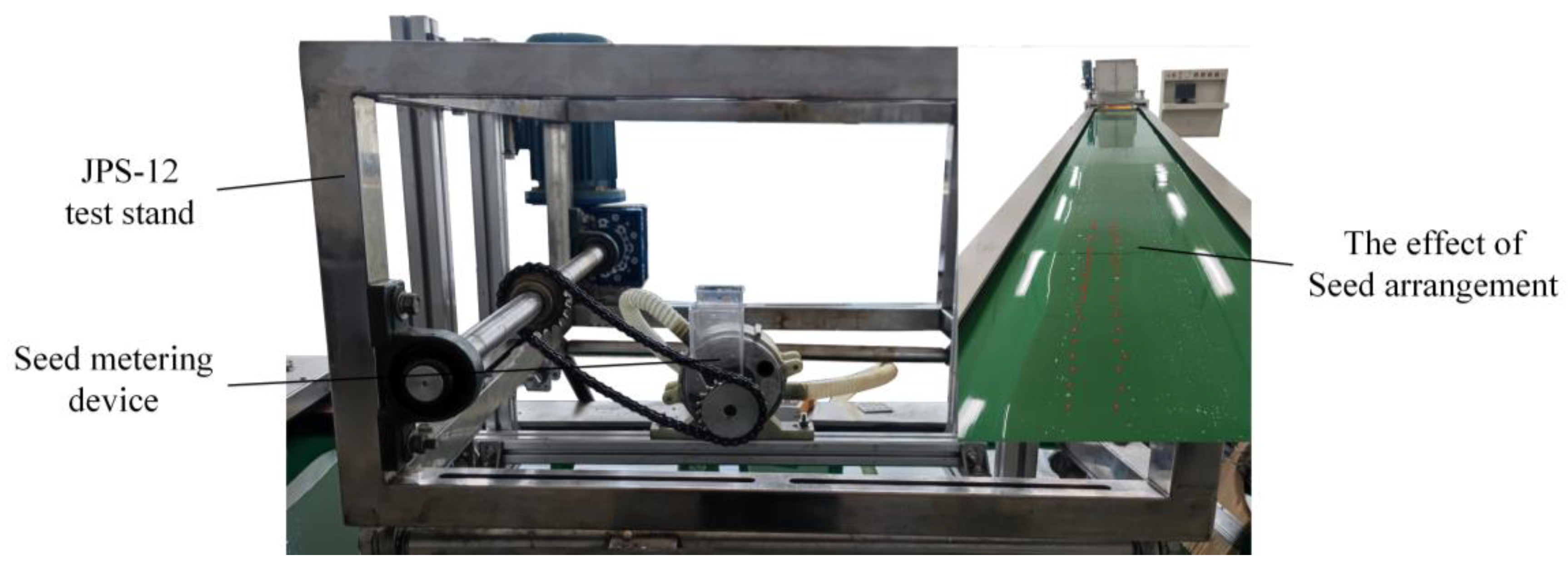
The seed arrangement performance test stand utilizes the JPS-12 seed arrangement performance test stand as its base; additionally, it includes a vortex air pump and a pneumatic hill-drop seed metering device for rapeseed, etc., as illustrated in Figure 11.
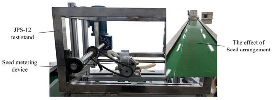
Figure 11.
Seed arrangement performance test stand.
3.5. Index for Evaluating the Performance of the Seed Metering Device
3.5.1. Index for Evaluation of Seed Filling Effectiveness
According to the national standard GB/T 6973-2005, “Single seed (precision) planter test method” [34], 260 seeds were selected as a group of tests, and each group of tests was conducted three times. The average value was used as the final test result for analysis, and the qualified rate and leakage rate of absorption were used as the performance evaluation indicators for the seed arrangement. Using the Formula (15), the following performance indicators are determined:
where W is qualified rate, Q is leakage rate of absorption, n1 is the number of suction holes that absorb 1–2 seeds at a time, n2 is the number of suction holes without adsorbed seeds, and N’ is the total number of suction holes within the statistical range.
3.5.2. Index for Evaluation of Seed Arrangement Effectiveness
Using the industry standard NY/T 1143-2006, “Technical Specification for Seed Planter Quality Evaluation” [35], the two indices used to evaluate the performance of seed planters are identified as hole number qualified rate and empty broadcast rate, and their respective calculation formulas are shown in Formula (16).
where Xk is the empty broadcast rate, Xh is the hole number qualified rate, x1 is the number of holes in which no seeds are present, and x2 is the qualified rate of the hole in which the number of seeds is 1 or 2; xn is the total number of holes within the statistical range.
3.6. Single-Factor Experimental Design
In order to see how the diameter and shape of the suction holes affect how well the seeds are filled, and to choose the best diameter and shape parameters for the suction holes, the diameter of the suction hole and the shape of the suction hole were taken as test factors. The performance evaluation indices for the single-factor optimization test of suction hole diameter and suction hole shape were the leakage absorption rates and the qualified rate of seed filling. According to the theoretical analysis, the working speed range of the planter plate is selected as 10–90 r/min, and the working negative pressure range is selected as −0.5 to −2.5 kPa. The values of test factors and their corresponding level codes are displayed in the Table 1 below.

Table 1.
Experimental factors and level codes of single-factor experiments.
3.7. Seed Arrangement Performance Experimental Design
In order to determine the optimal combination of working parameters for the seed metering device, the rotation orthogonal test was conducted based on the seed filling performance test. As test factors, the speed of the planter plate and negative pressure were chosen, while the hole number qualified rate and empty broadcast rate were chosen as performance evaluation indices. The factor values and level codes for the orthogonal test are shown in the Table 2 below.
Table 2.
Experimental factors and level codes of seed arrangement performance experiments.
4. Results
4.1. Analysis of Fluent Simulation Results
4.1.1. Influence of Suction Hole Shape on Velocity Flow Field
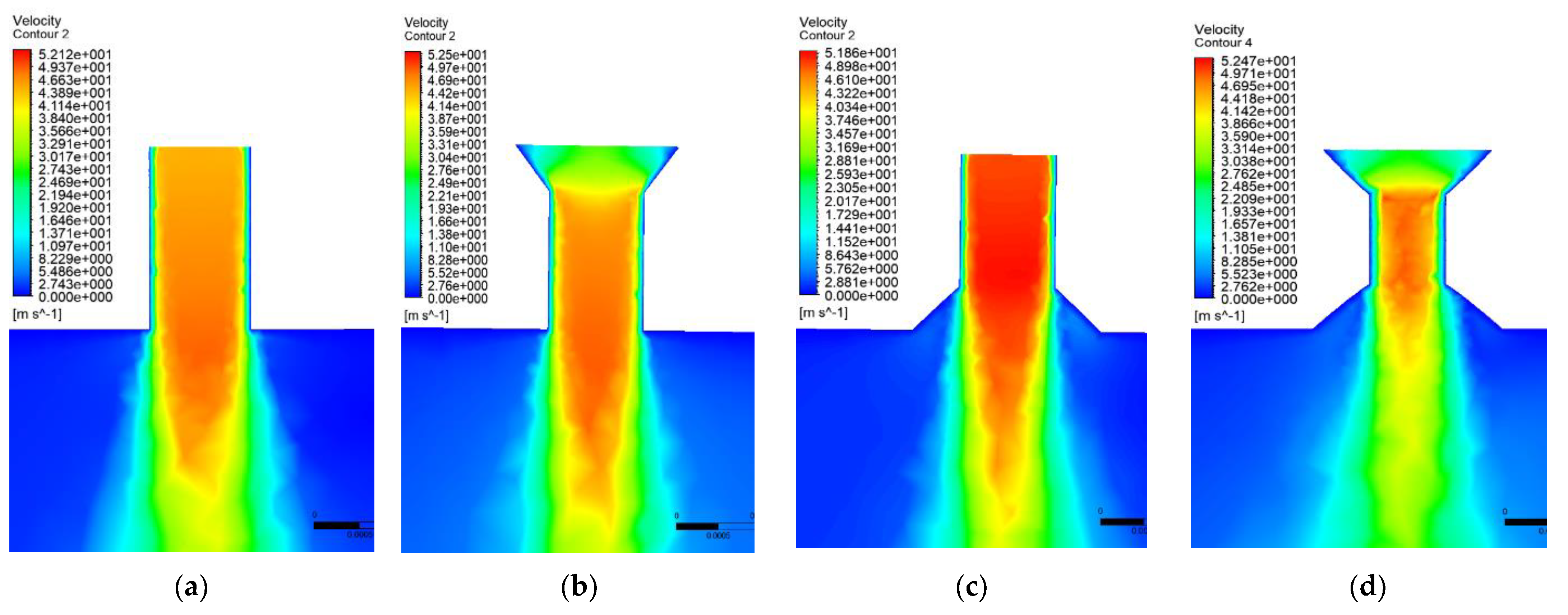
As shown in Figure 12 and Figure 13, the simulation results indicate that the greatest velocity of the negative pressure chamber occurs at the suction hole. According to the velocity cloud diagram, the overall velocities of the cylindrical-shaped suction hole and the horn-shaped suction hole are relatively uniform, and the maximum velocities are 49.49 m/s and 52.10 m/s, respectively. The velocity difference between a funnel-shaped hole and a diabolo-shaped hole is obvious, and the maximum velocity occurs at the smallest end aperture, which is 50.22 m/s and 50.13 m/s, respectively.
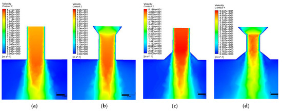
Figure 12.
Velocity cloud image of the suction hole section. (a) Cylindrical-shaped suction hole; (b) Funnel-shaped suction hole; (c) Horn-shaped suction hole; (d) Diabolo-shaped suction hole.
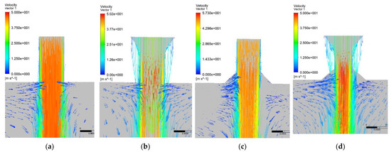
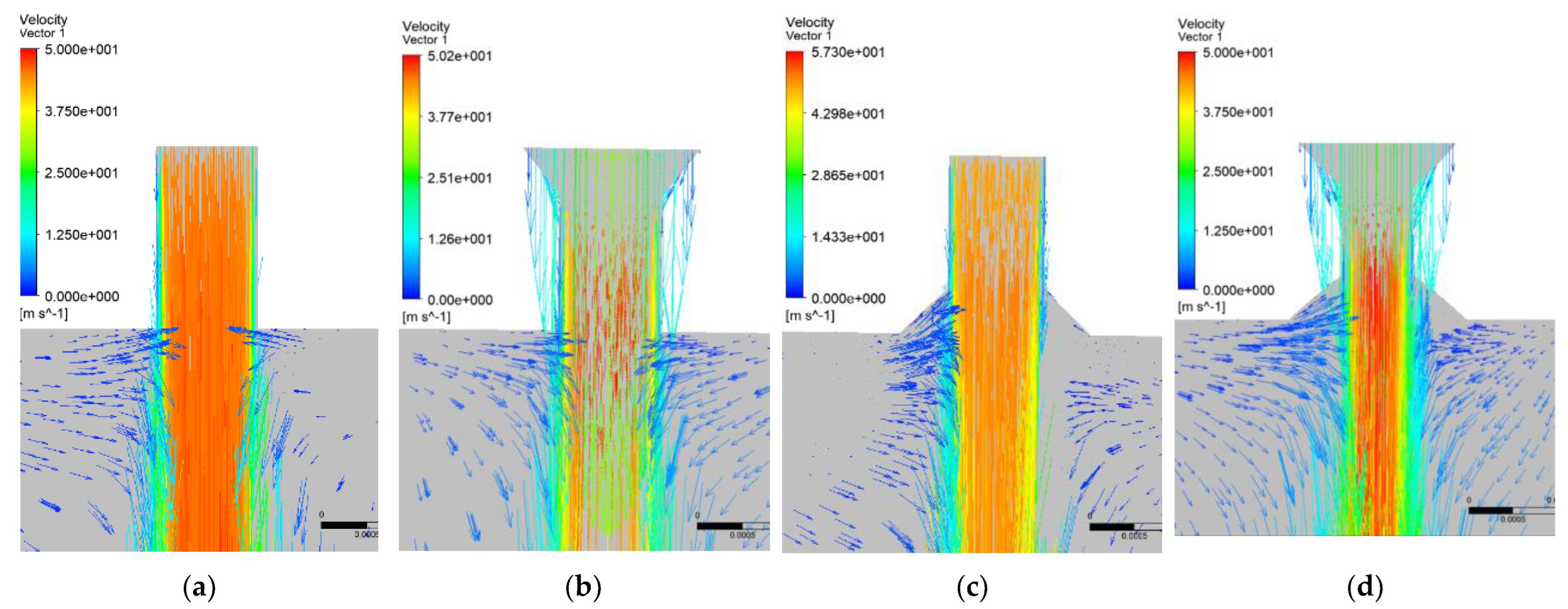
Figure 13.
Velocity vector diagram of the suction hole section. (a) Cylindrical-shaped suction hole; (b) Funnel-shaped suction hole; (c) Horn-shaped suction hole; (d) Diabolo-shaped suction hole.
4.1.2. Influence of Suction Hole Shape on Pressure Flow Field
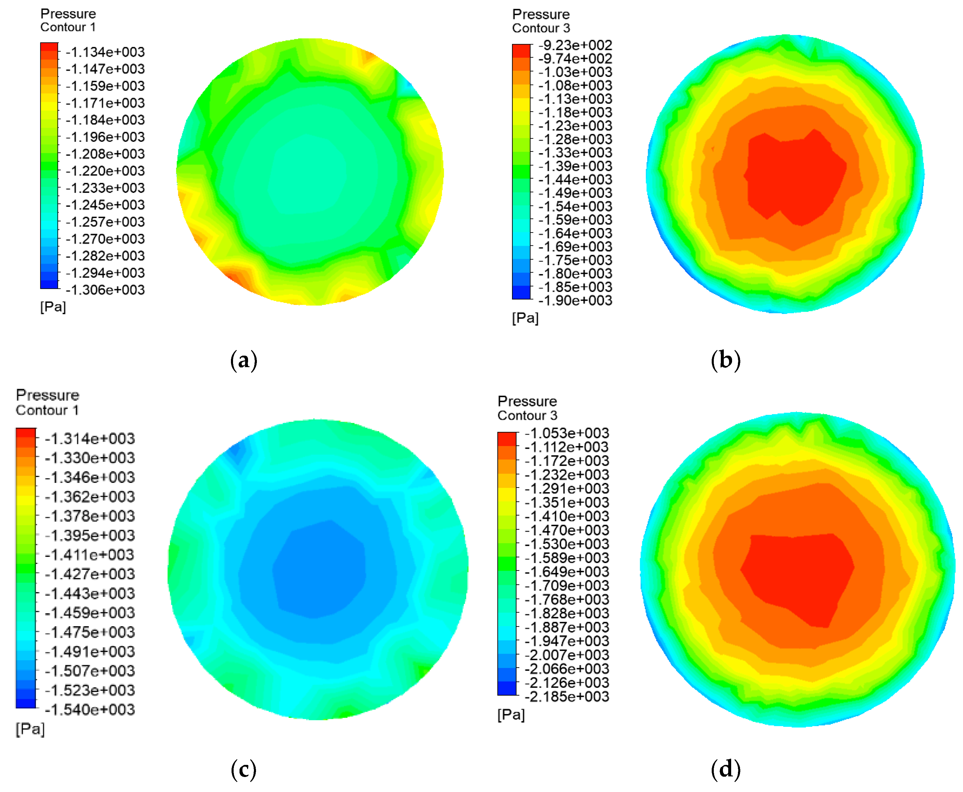
Figure 14 depicts the pressure nephogram of the end section face with different-shaped suction holes. The pressure nephogram of the funnel and diabolo-shaped suction holes displayed a concentric circular stratified distribution; the pressure decreased from the circle’s periphery to its center, and the change in pressure was evident. Cylindrical and horn-shaped suction holes are distributed radially, pressure increases from the perimeter to the center of the circle, and pressure changes slowly. On the suction end face of each suction hole, the average negative pressure is −1216.2 p, −1186.9 p, −1445.1 p, and −1379.8 p, respectively. The average pressure value of the funnel-shaped suction hole and the diabolo-shaped suction hole suction section is low, the maximum pressure is concentrated in a small range in the center of the circle, the internal and external pressure difference is high, and the adsorption stability of seeds is poor. The difference in pressure between the cylindrical-shaped suction hole and the horn-shaped suction hole is small, and suction stability is improved, whereas the average pressure value of the horn-shaped suction hole is greater than that of the cylindrical-shaped suction hole. According to the analysis of the pressure nephogram of the suction end face, under the same conditions, the horn-shaped suction end face is able to achieve a greater negative pressure of suction seed and has greater suction stability. Taking into account how the horn shape affects the flow fields of speed and pressure, the best horn-shaped suction hole is chosen for further design testing.

Figure 14.
Suction end face pressure cloud. (a) Cylindrical-shaped suction hole; (b) Funnel-shaped suction hole; (c) Horn-shaped suction hole; (d) Diabolo-shaped suction hole.
4.2. The Results of the Single Factor Test
4.2.1. Influence of Suction Hole Diameter on the Performance of Seed Filling
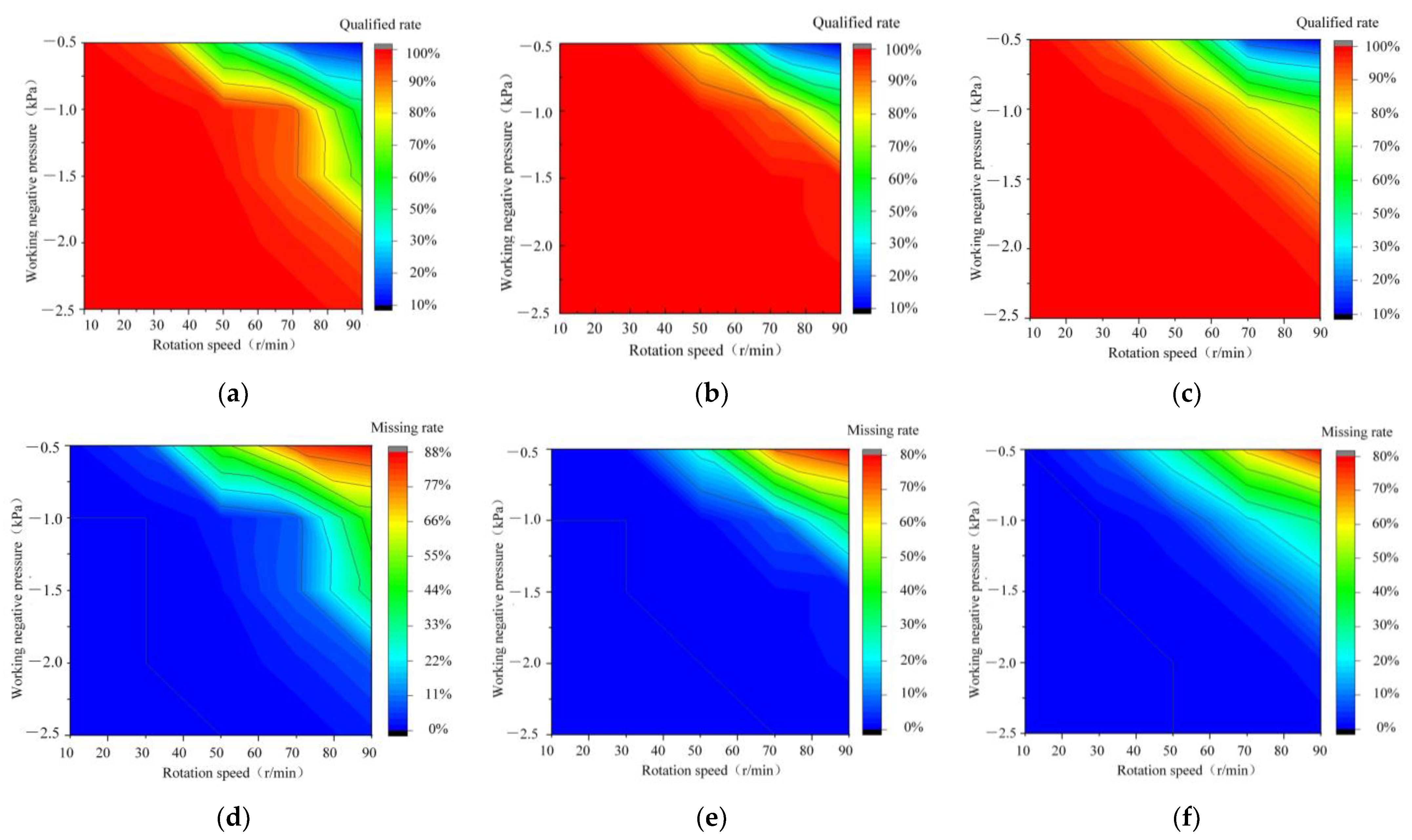
It can be seen from Figure 15 that the seed filling performance of different suction hole diameters changes similarly under the influence of the rotating speed of the planter plate and negative pressure. When the rotating speed is held constant, the qualified rate of seed filling decreases and the leakage rate rises as the rotating speed increases. When work speed is fixed within a certain range with an increase in negative pressure, the qualified rate of seed filling shows a trend of increasing gradually and leveling off after the first, while the leakage rate of absorption steadily shows a trend of decreasing gradually and leveling off after the first. The optimal working negative pressure range of a planter plate with different hole diameters is found to be approximately −2.5–−1.5 kPa, and the optimal working rotating speed is approximately 30–70 r/min. However, there are obvious differences between the rotation speed of planter plates with different hole diameters and the stable negative pressure range. As shown in the illustration, the stable working range of the planter plate with a 1.2 mm diameter hole is relatively large, as are the applicable working conditions.
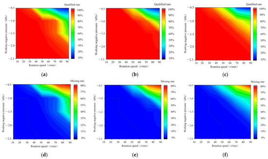
Figure 15.
Various diameters of suction hole performance contour map. (a) 1.1 mm diameter of suction hole filling qualified rate contour map; (b) 1.2 mm diameter of suction hole filling qualified rate contour map; (c) 1.3 mm diameter of suction hole filling qualified rate contour map; (d) 1.1 mm diameter of suction hole leakage rate contour map; (e) 1.2 mm diameter of suction hole leakage rate contour; (f) 1.3 mm diameter of suction hole leakage rate contour.
4.2.2. Influence of Suction Hole Shape on Seed Filling Performance
Figure 16 and Figure 17 demonstrate that, In the optimal working interval, the filling qualified rate and leakage rate of seed filling with various suction hole shapes differ significantly. Compared to cylindrical-shaped suction holes, funnel-shaped suction holes perform the worst at filling seeds. The performance of the horn-shaped suction hole filler is superior to that of the diabolo-shaped suction hole filler. The experimental results are consistent with the simulation results, indicating that CFD can be used to investigate the impact of suction hole shapes on seed filling performance.
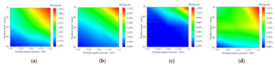
Figure 16.
Contour map of the leakage rate of seed filling in different-shaped suction holes. (a) Cylindrical-shaped suction hole; (b) Funnel-shaped suction hole; (c) Horn-shaped suction hole; (d) Diabolo-shaped suction hole.
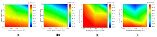
Figure 17.
Contour map of the quality rate of seed filling in different-shaped suction holes. (a) Cylindrical-shaped suction hole; (b) Funnel-shaped suction hole; (c) Horn-shaped suction hole; (d) Diabolo-shaped suction hole.
4.2.3. Comparison of Optimized and Original Planter Plates
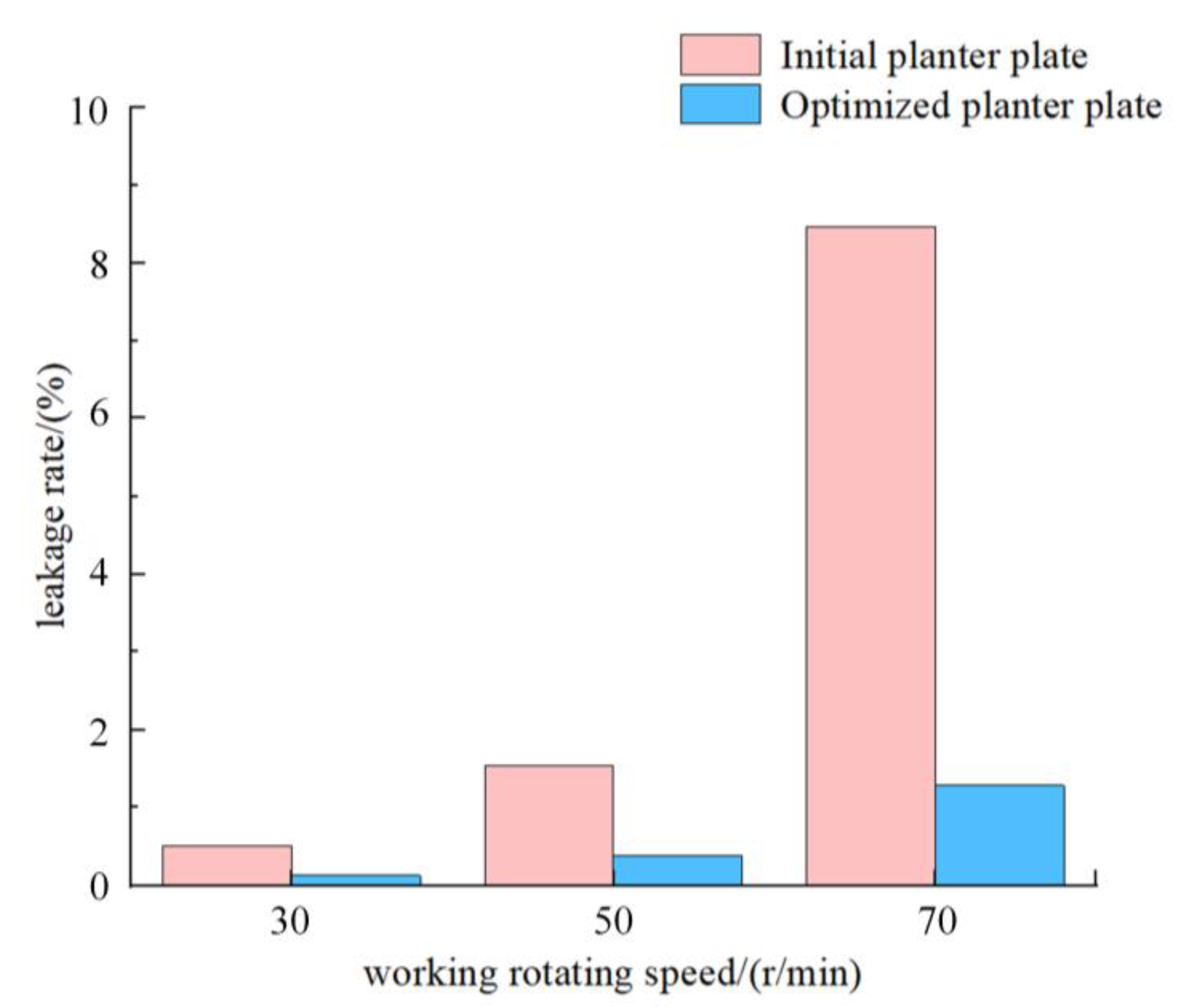
Compared to the initial planter plate, which has a suction hole with a diameter of 1.1 mm and a cylindrical shape, the optimized planter plate has a suction hole with a diameter of 1.2 mm and a horn shape. To evaluate the seed filling performance of the optimized and initial planter plate under low negative pressure, the planter plate speed is set to 20 r/min intervals, 30, 50, and 70 r/min for the seed filling test, with the leakage rate serving as the evaluation index. Figure 18 demonstrates the results. Clearly, the optimized planter plate has a lower leakage rate than the original planter plate. The gap between the optimized planter plate’s leakage rate and its speed widens as the rotation speed increases. When the speed of the planter plate is 30 r/min, the optimized planter plate has a leakage rate that is 0.385 percentage points less than the original planter plate. When the rotational speed of the planter plate increases to 70 r/min, the optimized planter plate’s leakage rate is 7.18 percentage points lower than that of the original planter plate.

Figure 18.
Comparison of seed filling performance between an initial planter plate and an optimized planter plate.
4.3. The Results of the Seed Arrangement Performance Test
The test results for the seed arrangement performance are shown in Table 3.
Table 3.
The test results for the seed arrangement performance.
4.3.1. ANOVA Results of the Hole Number Qualified Rate
Design-expert 13 was used to conduct variance analysis on the seed arrangement performance test results, and the outcomes are displayed in the Table 4. A, B, and AB have a significant impact on the qualified rate, whereas A2 and B2 have no impact on the qualified rate index. According to the results of variance analysis, the following regression equation can be derived to describe the impact of A, B, and AB on the qualified rate:
Table 4.
Variance analysis of hole number qualified rate.
According to the results of the loss of fit test of the regression equation presented previously, the p value of the loss of fit term is greater than 0.05, which is not statistically significant. The regression equation is in good agreement with the experimental values of the hole number qualified rate index, and there is a significant quadratic correlation between the hole number qualified rate index and the experimental factors listed above.
4.3.2. ANOVA Results of the Empty Broadcast Rate
Design-expert 13 was used to conduct variance analysis on the seed arrangement performance test results, and the outcomes are displayed in the Table 5. A, B, and B2 have a highly significant effect on the index of empty broadcast rate, whereas AB and A2 have no significant effect. According to the results of ANOVA, the following regression equation can be derived to describe the influence of A, B, and B2 on the empty broadcast rate:
Table 5.
Variance analysis of the empty broadcast rate.
According to the results of the loss of fit test of the regression equation presented previously, the p value of the loss of fit term is greater than 0.05, which is not statistically significant. The regression equation is in good agreement with the experimental values of the empty broadcast rate index, and there is a significant quadratic correlation between the empty broadcast rate index and the experimental factors listed above.
4.3.3. Results of Response Surface Methodology (RSM) for Experimental Evaluation Indicators
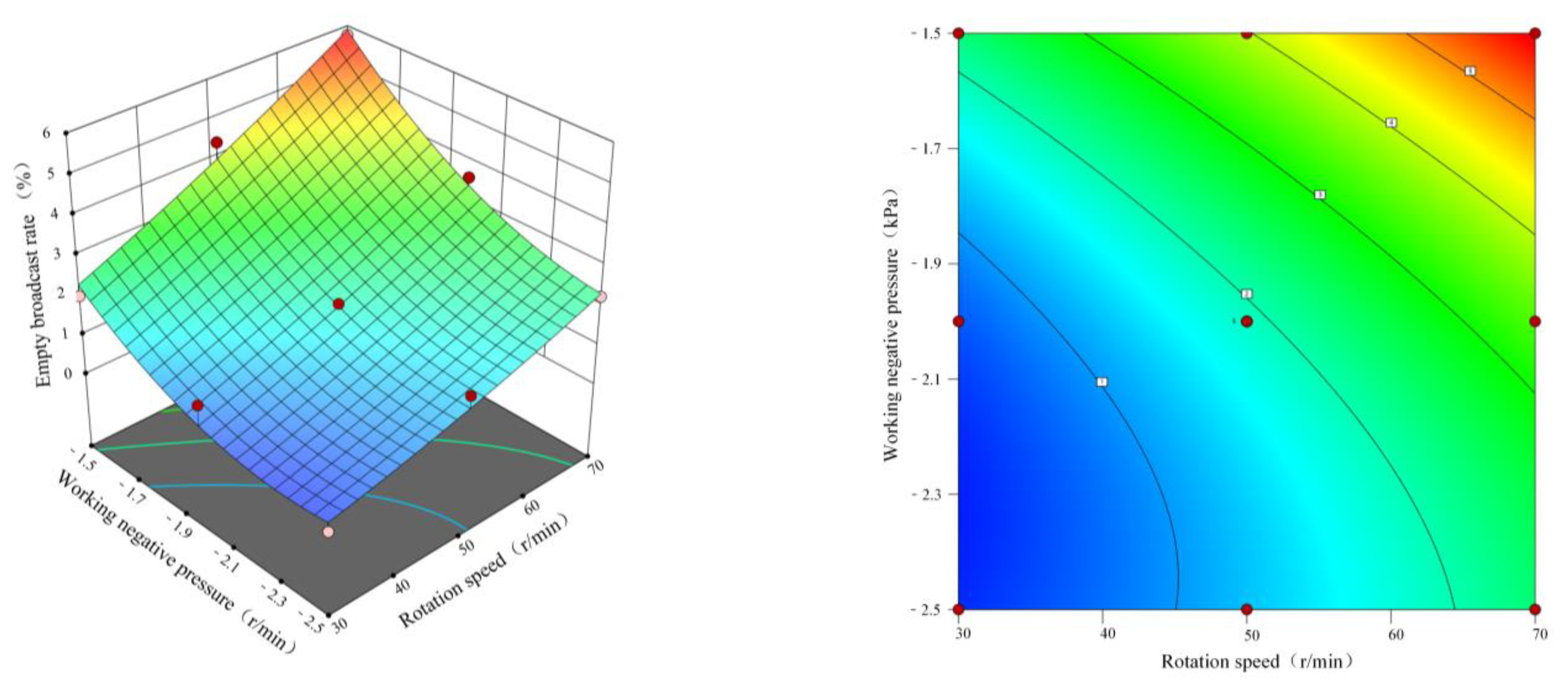
To gain a clearer and more intuitive understanding of the influence rule of each experimental factor on the evaluation index of seed arrangement performance, the response surface was utilized in Design Expert 13 to study the impact of experimental factors on the evaluation index of seeding performance. Figure 19 depicts the response surface and corresponding projection contour of the influence of experimental factors on the empty broadcast rate.
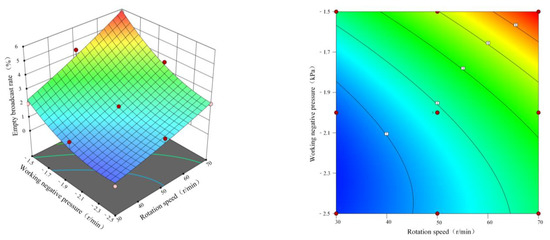
Figure 19.
Response surface diagram of the empty broadcast rate.
When the diameter of the suction hole is 1.2 mm, Figure 19 depicts the response sur-face of the interaction between negative pressure and rotational speed on the empty broadcast rate. When the negative pressure remains constant, the empty broadcast rate rises as the rotational speed increases. When the negative pressure is −2.0 to −1.5 kPa, the range of the empty broadcast rate change is greater. When the negative pressure is −2.5 to −2.0 kPa, the empty broadcast rate change range is small.
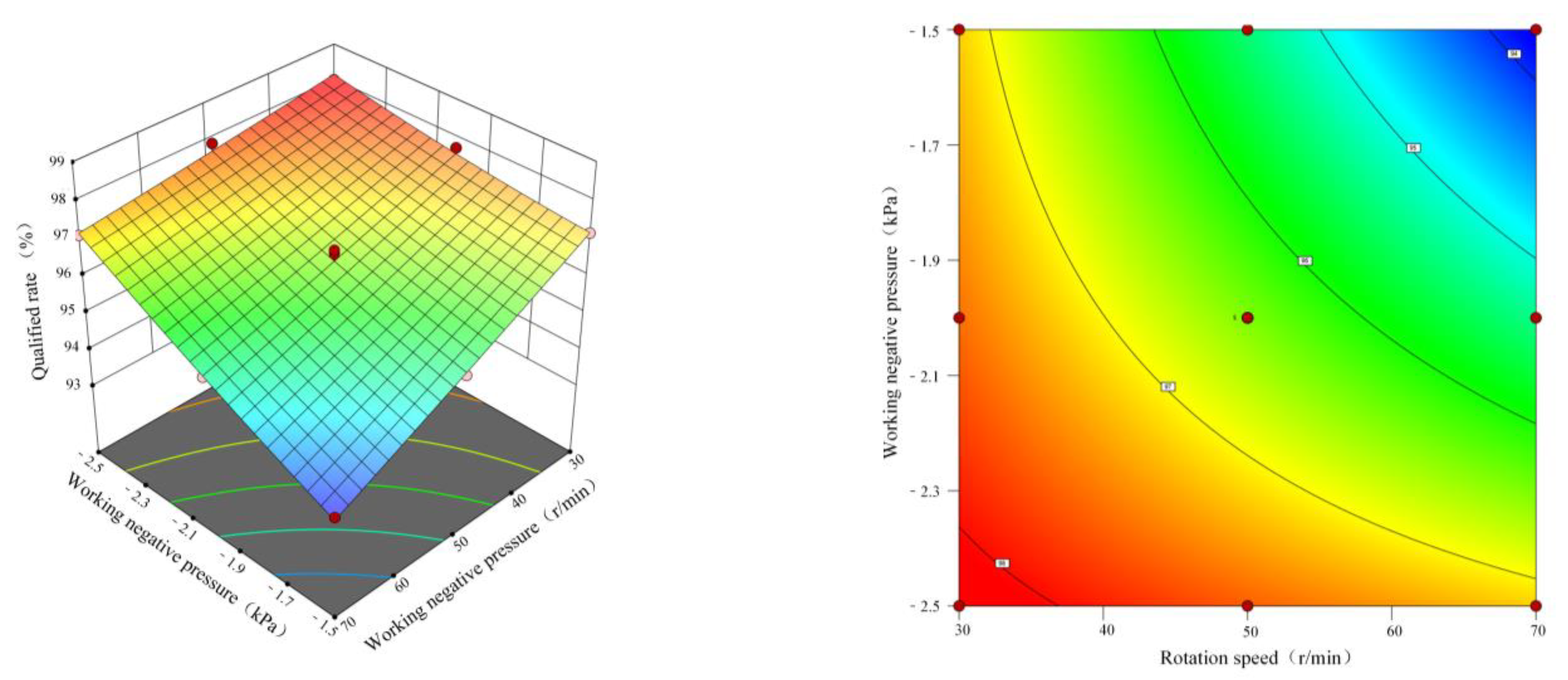
When the diameter of the suction hole is 1.2 mm, Figure 20 depicts the response sur-face of the interaction between negative pressure and rotational speed on the hole number qualified rate. With constant negative pressure, the hole number qualified rate decreases as the rotational speed increases. When the negative pressure is between −2.0 and −1.5 kPa, the hole number qualified rate variation is greater. When the negative pressure is between −2.5 and −2.0 kPa, the change range of the hole number qualified rate is small because the negative pressure provides a large adsorption force. When the range of rotational speed is between 50 and 70 r/min, the change range of the hole number qualified rate is substantial. When the rotational speed is between 30 and 50 r/min, the hole number qualified rate has a small range of variation.
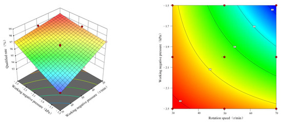
Figure 20.
Response surface diagram of the hole number qualified rate.
4.3.4. The Optimal Parameter Combination of Experimental Factors
The lower the empty broadcast rate, the higher the hole number qualified rate, and the better the performance of the seed metering device. Design-Expert software was used to optimize the aforementioned two evaluation indicators, with the following optimization objective Formula (17):
The objective function was solved using Design-Expert software, and the optimization results were evaluated three times, as shown in Table 6. According to the table, under the conditions of a planter plate rotation speed of 30–70 r/min, the empty broadcast rate is less than 3%, the hole number qualified rate is greater than 96%, and the error between the theoretical optimization results is less than 5.5%, indicating that the fitting model has a high degree of dependability.
Table 6.
Optimization results and test verification.
5. Discussion
Through CFD simulation, the horn-shaped suction hole is optimized in this study. As depicted in Figure 12, Figure 13 and Figure 14, when there is a chamfer on the outer end face of the suction hole, the air flow enters along the cone and intersects with the vertical air flow at the end of the cone, resulting in a force interaction that causes local pressure loss and thus affects the flow field’s stability. When there is a chamfer on the inner end face of the suction hole, the air flow along the inner end of the shaped hole is diffused, which is conducive to the rapid passage of the air flow, resulting in a higher flow rate and making seed filling more feasible.
According to the test results of the effect of suction hole diameter on seed filling performance, when negative pressure remains constant, the filling qualified rate of seed filling is negatively correlated with speed, whereas the leakage absorption rate is positively correlated with speed. The reason for this is that the adsorption time of seeds from the population for the suction hole decreases when the negative pressure remains constant and the rotating speed increases. Failure of the suction hole to absorb seeds in a timely manner results in an increase in leakage rates and a decrease in the qualified rate of seed filling. As negative pressure increases, both the growth rate of filling qualified rate and the decrease rate of leakage filling rate decrease gradually. The reason for this is that the working speed remains constant and the negative pressure increases, the adsorption capacity of the suction hole on the seeds increases, and the suction hole can absorb and transport the seeds from the population steadily. However, when the negative pressure reaches a certain threshold, the phenomenon of seed re-suction will influence the effect of seeding. The experimental results are in agreement with those of previous studies [36].
It can be seen from the test results of the influence of the shape of the suction hole on seed filling that when the end face of the suction hole is chamfered, it can better conform to the shape of the seed. The presence of chamfer can effectively reduce the blocking effect of the population on the seed and the leakage rate during the transport of seeds. Due to the chamfering, however, the seed suction end face of the shaped hole could not make direct contact with the population, which increased the difficulty of adsorption and separation of seeds from the population and decreased the filling qualified rate. When there is chamfering on the inner end face of the suction hole, the gas flow through the suction hole increases within a unit of time, and the suction hole end face obtains a greater seed suction negative pressure, which has a greater capacity for adsorbing seeds. When chamfering is present on both the inner and outer end faces of the suction hole, the chamfering on the inner end faces can improve the suction end faces’ negative pressure. However, as the length of the shaped hole channel decreases, the stability of the airflow field decreases, resulting in an increase in the filling qualified rate but a decrease in regularity. In conjunction with the results of the CFD simulation, it is demonstrated that the CFD simulation can be utilized to optimize the structural parameters of the pneumatic seed metering device [37].
It can be seen from the test results of seeding performance that when the negative pressure is between −2.0 and −1.5 kPa, as the rotating speed increases, the seed filling time decreases, and the low negative pressure cannot provide sufficient suction, leading to an increase in the empty broadcast rate. When the negative pressure is between −2.5 and −2.0 kPa, as the rotational speed increases, the seed filling time decreases. Sufficient suction can be provided under conditions of high negative pressure, so the change in empty broadcast rate is slow. When the negative pressure is between −2.0 and −1.5 kPa, under conditions of low negative pressure, as the rotational speed in-creases, the seed filling time decreases, and the adsorption force provided by negative pressure decreases, leading to an increase in the empty broadcast rate and a decrease in the hole number qualified rate. When the negative pressure is between −2.5 and −2.0 kPa, because the negative pressure provides a large adsorption force, with the increase in rotating speed, the seed filling time decreases and the empty broadcast rate increases slightly, so the hole number qualified rate decreases less. When the range of rotational speed is between 50 and 70 r/min, with the same aperture and a higher rotational speed, the filling time is reduced. Negative pressure has a significant effect on the stability of seed suction. With an increase in negative pressure, the adsorption capacity of the seeds increases, as does the stability of seed adsorption, resulting in a decrease in the empty broadcast rate and a wide range of variation for the hole number qualified rate. When the rotational speed is between 30 and 50 r/min, under identical aperture and rotational speed conditions, the seed filling time is lengthy, and negative pressure has a negligible effect on the stability of seed suction. As a result, as the negative pressure increases, there is little variation in the adsorption pass rate.
6. Conclusions
The key structural parameters influencing the performance of the planter plate were analyzed and determined. The planter plate’s structure was optimized to improve the performance of the precision seed metering device. Using high-speed photography, the effects of different hole diameters on the filling performance of the seed metering device were analyzed. According to the results, the optimal working negative pressure range was −2.5–−1.5 kPa, and the optimal seed plate speed range was 30–70 r/min. The difference in the seed filling performance of the three types of hole diameter plates was small within the optimal working parameter range. While outside the optimal working parameter range, the seed filling performance of the plate with a suction hole diameter of 1.2 mm was superior to that of the plates with suction hole diameters of 1.1 and 1.3 mm. Fluent simulation and bench testing were used to assess the effect of different hole shapes on seed filling performance. The simulation results indicate that, under identical conditions, the flow field inside the funnel-shaped suction hole is stable and the average pressure on the end face of the funnel-shaped suction hole is maximal. The bench test results demonstrate that the Fluent simulation results are consistent with the test results, and Fluent can be used to investigate the effect of the flow field parameters of the hole shape on the filling performance. Within the range of optimal working parameters, a test of the seed arrangement performance was conducted, and the effects of negative pressure and rotation speed were analyzed. Within the range of optimal working parameters, the hole number qualified rate was no less than 93%, the empty broadcast rate was no more than 6%, and the performance of the pneumatic hill-drop seed metering device for rapeseed was significantly improved. However, the mechanism by which the structure of the suction hole affects the seed filling performance and the minimum negative pressure required by the seed metering device under different rotating speed conditions is still unclear and will require further investigation.
Author Contributions
Conceptualization, Z.L.; methodology, J.W.; software, J.W.; validation, D.D.; formal analysis, J.D.; investigation, J.W.; resources, D.D.; data curation, J.D.; writing—original draft preparation, J.W.; writing—review and editing, Z.L.; supervision, T.Z.; project administration, Y.C.; funding acquisition, Z.L. All authors have read and agreed to the published version of the manuscript.
Funding
This study came from the National Natural Science Foundation of China: adsorption mechanism and mechanism of rapeseed high-speed precision sowing with grooved teeth directional disturbance (51805004); Rice-wheat (oil) mechanization and intelligent production management technology and equipment research and development (2022YFD2301402).
Data Availability Statement
The data presented in this study are available on request from the corresponding author.
Acknowledgments
We thank the engineering training center of AnHui Agricultural University for providing the test site.
Conflicts of Interest
The authors declare no conflict of interest.
References
- Liao, Q.X.; Lei, X.L.; Liao, Y.T.; Ding, Y.C.; Zhang, Q.S.; Wang, L. Research Progress of Precision Seeding for Rapeseed. Trans. Chin. Soc. Agric. Mach. 2017, 48, 9. [Google Scholar]
- Xing, H.; Zang, Y.; Wang, Z.M.; Luo, X.W.; Pei, J.; He, S.Y.; Xu, P.; Liu, S.C. Design and parameter optimization of rice pneumatic seeding metering device with adjustable seeding rate. Trans. Chin. Soc. Agric. Eng. 2019, 35, 20–28. [Google Scholar]
- Li, Z.D.; Lei, X.L.; Cao, X.Y.; Liao, Y.T.; Liao, Q.X.; Li, S.S. Design and experiment of pneumatic-typed precision centralized metering device for rapeseed. Trans. Chin. Soc. Agric. Eng. 2015, 31, 9–17. [Google Scholar]
- Hu, M.J.; Xia, J.F.; Zheng, K.; Du, J.; Liu, Z.Y.; Zhou, M.K. Design and Experiment of Inside-filling Pneumatic High Speed Precision Seed-metering Device for Cotton. Trans. Chin. Soc. Agric. Mach. 2021, 52, 73–85. [Google Scholar]
- Zhang, Q.S.; Liao, Q.X.; Xiao, W.L.; Liu, X.P.; Wei, G.L.; Liu, L.C. Research process of tillage technology and equipment for rapeseed growing. Chin. J. Oil Crop Sci. 2018, 40, 702–711. [Google Scholar]
- Kuai, J.; Wang, J.J.; Zuo, Q.S.; Chen, H.L.; Gao, J.Q.; Wang, B.; Zhou, G.S.; Fu, T.D. Effects and Mechanism of Higher Plant Density on Directly-Sown Rapeseed in the Yangtze River Basin of China. Sci. Agric. Sin. 2018, 51, 4625–4632. [Google Scholar]
- Yin, W.Q.; Zhao, L.; Li, H.; Hu, F.; Yu, H.M. Design and Experiment on Suction Nozzle Type Hole of Pneumatic-sheave Combined Vegetable Precision Metering Device. Trans. Chin. Soc. Agric. Mach. 2019, 50, 68–76, 136. [Google Scholar]
- Liao, Q.X.; Zhang, M.; Yu, J.J.; Liu, X.H. Pneumatic Centralized Metering Device for Rapeseed. Trans. Chin. Soc. Agric. Mach. 2011, 42, 30–34. [Google Scholar]
- Li, J.H.; Lai, Q.H.; Zhang, H.; Zhang, Z.G.; Zhao, J.W.; Wang, T.T. Suction force on high-sphericity seeds in an air-suction seed-metering device. Biosyst. Eng. 2021, 211, 125–140. [Google Scholar] [CrossRef]
- Li, Z.D.; He, S.; Zhong, J.Y.; Han, J.F.; Chen, Y.X.; Song, Y. Parameter optimization and experiment of the disturbance pneumatic plate hole metering device for rapeseed. Trans. Chin. Soc. Agric. Eng. 2021, 37, 1–11. [Google Scholar]
- Jin, X.; Li, Q.W.; Zhao, K.X.; Zhao, B.; He, Z.T.; Qiu, Z.M. Development and test of an electric precision seeder for small-size vegetable seeds. Int. J. Agric. Biol. Eng. 2019, 12, 75–81. [Google Scholar] [CrossRef]
- Cheng, X.P.; Lu, C.Y.; Meng, Z.J.; Yu, J.Y. Design and parameter optimization on wheat precision seed meter with combination of pneumatic and type hole. Trans. Chin. Soc. Agric. Eng. 2018, 34, 1–9. [Google Scholar]
- Li, Z.H.; Wang, D.C.; Liu, G.L.; Yang, M.S.; Wang, Z.H. CFD simulation and improvement of air-stream distributive metering device. Trans. Chin. Soc. Agric. Mach. 2009, 40, 64–68. [Google Scholar]
- Lei, X.L.; Liao, Y.T.; Zhang, Q.S.; Wang, L.; Liao, Q.X. Numerical simulation of seed motion characteristics of distribution head for rapeseed and wheat. Comput. Electron. Agric. 2018, 150, 98–109. [Google Scholar] [CrossRef]
- Lei, X.L.; Hu, H.J.; Yang, W.H.; Liu, L.Y.; Liao, Q.X.; Ren, W.J. Seeding performance of air-assisted centralized seed-metering device for rapeseed. Int. J. Agric. Biol. Eng. 2021, 14, 79–87. [Google Scholar] [CrossRef]
- Ibrahim, E.J.; Liao, Q.X.; Wang, L.; Liao, Y.T.; Yao, L. Design and experiment of multi-row pneumatic precision metering device for rapeseed. Int. J. Agric. Biol. Eng. 2018, 11, 116–123. [Google Scholar]
- Gaikwad, B.B.; Sirohi, N.P.S. Design of a low-cost pneumatic seeder for nursery plug trays. Biosyst. Eng. 2008, 99, 322–329. [Google Scholar] [CrossRef]
- Yazgi, A.; Degirmencioglu, A. Optimisation of the seed spacing uniformity performance of a vacuum-type precision seeder using response surface methodology. Biosyst. Eng. 2007, 97, 347–356. [Google Scholar] [CrossRef]
- Karayel, D.; Barut, Z.B.; Özmerzi, A. Mathematical Modelling of Vacuum Pressure on a Precision Seeder. Biosyst. Eng. 2004, 87, 437–444. [Google Scholar] [CrossRef]
- Yatskul, A.; Lemiere, J.; Cointault, F. Influence of the divider head functioning conditions and geometry on the seed’s distribution accuracy of the air-seeder. Biosyst. Eng. 2017, 161, 120–134. [Google Scholar] [CrossRef]
- Dai, Y.Z.; Luo, X.W.; Zhang, M.H.; Lan, F.; Zhou, Y.J.; Wang, Z.M. Design and experiments of the key components for centralized pneumatic rice dry direct seeding machine. Trans. Chin. Soc. Agric. Eng. 2020, 36, 1–8. [Google Scholar]
- Li, Y.H.; Yang, L.; Zhang, D.X.; Cui, T.; Zhang, K.L.; Xie, C.J.; Yang, R.M. Analysis and test of linear seeding process of maize high speed precision metering device with air suction. Trans. Chin. Soc. Agric. Eng. 2020, 36, 26–35. [Google Scholar]
- Liao, Y.T.; Liao, Q.X.; Wang, L.; Zheng, J.; Gao, L.P. Investigation on vacuum singulating effect influencing factors of pneumatic precision seed metering device for small particle size of seeds. Trans. Chin. Soc. Agric. Eng. 2018, 34, 10–17. [Google Scholar]
- Li, Z.D.; Yang, W.C.; Zhang, T.; Wang, W.W.; Zhang, S.; Chen, L.Q. Design and suction performance test of sucking-seed plate combined with groove-tooth structure on high speed precision metering device of rapeseed. Trans. Chin. Soc. Agric. Eng. 2019, 35, 12–22. [Google Scholar]
- Zhang, G.Z.; Luo, X.W.; Zang, Y.; Wang, Z.M.; Zeng, S.; Zhou, Z.Y. Experiment of sucking precision of sucking plate with group holes on rice pneumatic metering device. Trans. Chin. Soc. Agric. Eng. 2013, 29, 13–20. [Google Scholar]
- Li, Y.H.; Yang, L.; Zhang, D.X.; Cui, T.; Ding, L.; Wei, Y.N. Design and Experiment of Pneumatic Precision Seed-metering Device with Single Seed-metering Plate for Double-row. Trans. Chin. Soc. Agric. Mach. 2019, 50, 61–73. [Google Scholar]
- Liu, H.; Liao, Y.T.; Wang, L.; Wang, B.S.; Du, Z.; Liao, Q.X. Design and Experiment of Positive and Negative Pressure Combination Precision Metering Device for Pakchoi. Trans. Chin. Soc. Agric. Mach. 2022, 53, 54–65. [Google Scholar]
- Chinese Academy of Agricultural Machinery. Agricultural Machinery Design Manual; Agricultural Science and Technology Press: Beijing, China, 2007; Volume 1, p. 358. [Google Scholar]
- Xu, J.; Hou, J.; Wu, W.; Han, C.; Wang, X.; Tang, T.; Sun, S. Key Structure Design and Experiment of Air-Suction Vegetable Seed-Metering Device. Agronomy 2022, 12, 675. [Google Scholar] [CrossRef]
- Zhao, X.B. Engineering Fluid Mechanics, 3rd ed.; Southeast University Press: Nanjing, China, 2012. [Google Scholar]
- Department of Theoretical Mechanics, Harbin Institute of Technology. Theoretical Mechanics (I); Higher Education Press: Beijing, China, 2016; p. 317. [Google Scholar]
- Yan, B.X.; Zhang, D.X.; Yang, L.; Cui, T.; Zhong, X.J.; Li, Y.H. Performance Analysis of Gravity Assist Filling Precision Seed-metering Device with Synchronously Rotating Seed Plate and Vacuum Chamber. Trans. Chin. Soc. Agric. Mach. 2018, 49, 117–124. [Google Scholar]
- Zhang, K.X.; Li, J.F.; Song, Z.H.; Liu, X.X.; Liu, L. Optimum Design and Test of Variable Diameter Double Disc Air Suction Precision Seeder. Trans. Chin. Soc. Agric. Mach. 2019, 50, 52–63. [Google Scholar]
- GB/T 6973-2005; Single Seed (Precision) Planter Test Method. General Administration of Quality Supervision. Inspection and Quarantine of the People’s Republic of China: Beijing, China, 2006.
- NY/T 1143-2006; Technical Specification for Quality Evaluation of Planter. Ministry of Agriculture of the People’s Republic of China: Beijing, China, 2006.
- He, S. Analysis and Experiment on the Adsorption Mechanism of the Perturbation Pneumatic Precision Seed Metering Device for Rapeseed; Anhui Agricultural University: Hefei, China, 2021. [Google Scholar]
- Li, Z.; Zhang, H.; Xie, R.; Gu, X.; Du, J.; Chen, Y. Evaluation on the Performance of Airflow Distribution Device of Pneumatic Seeder for Rapeseed through CFD Simulations. Agriculture 2022, 12, 1781. [Google Scholar] [CrossRef]


Disclaimer/Publisher’s Note: The statements, opinions and data contained in all publications are solely those of the individual author(s) and contributor(s) and not of MDPI and/or the editor(s). MDPI and/or the editor(s) disclaim responsibility for any injury to people or property resulting from any ideas, methods, instructions or products referred to in the content. |
© 2023 by the authors. Licensee MDPI, Basel, Switzerland. This article is an open access article distributed under the terms and conditions of the Creative Commons Attribution (CC BY) license (https://creativecommons.org/licenses/by/4.0/).