Article

Fluid Movement Law and Influencing Factors of Shredding on Rice Straw Briquetting Machines

1
Key Laboratory of Modern Agricultural Equipment and Technology of Ministry of Education, Jiangsu University, Zhenjiang 212013, China
2
Key Laboratory of Crop Harvesting Equipment Technology of Zhejiang Province, Jinhua 321017, China
*
Author to whom correspondence should be addressed.
Agronomy 2022, 12(6), 1439; https://doi.org/10.3390/agronomy12061439
Submission received: 26 April 2022 / Revised: 3 June 2022 / Accepted: 14 June 2022 / Published: 16 June 2022

Abstract

:
The briquetting technology of rice straw could increase the bulk density of the straw, reduce transportation and storage costs, and improve resource utilization. This paper analyzed the working principle of the air-conveying integrated device in briquetting machines. High-speed photography technology was used to track and record the movement process of crushed straw material in the air-conveying cylinder area. It was compared with the simulation results of the average velocity of crushed straw material to verify the reliability of the simulation. The results showed that the flow of straw scraps in the straw-shredding and air-conveying integrated device was relatively stable when the impeller speed was 630 r/min, the number of blades was three, the blades were tilted back 15°, and the radius of curvature of the air-conveying tube elbow was 700 mm. At the same time, the speed distribution was uniform, and the highest throwing speed reached 4.5 m/s to 4.8 m/s. After optimization, the average increase rate of briquette density was 2.61% and the average increase rate of briquette productivity was 2.52%. The fluid movement law of the straw-shredding and air-conveying integrated device studied in this paper could be used to optimize the air-conveying device, improve the efficiency of straw briquetting and the utilization rate of straw resources.

1. Introduction

As the world’s abundant renewable lignocellulosic biomass, rice straw has great application potential due to its rapid growth and high yield, making it an important raw material for bioenergy production [1,2,3,4]. Every kilogram of rice grain harvested would produce 1–1.5 kg of excess rice straw, creating massive agricultural residues. Therefore, rice straw is one of the most abundant agricultural residues. Chinese annual output of rice straw reaches 270 million tons, making it the largest producer of rice straw globally [5,6]. The random accumulation of rice straw after the rice harvest severely restricts the further production and utilization of the straw. The messy accumulation of straw increases collection, transportation, and storage costs, and causes unnecessary energy loss at the same time. The utilization rate of straw resources in China is low, a large amount of straw is burned in the open on the spot. Although this treatment method has brought convenience to farmers, it discharges a large number of pollutants into the atmosphere, seriously polluting the environment and causing a waste of resources [7,8,9]. Using this straw to produce value-added products could not only reduce environmental pollution but is also of great significance to sustainable development [10,11]. The briquetting technology of rice straw could increase the bulk density of straw, reduce transportation and storage costs, and improve resource utilization [12,13,14]. Through the research on the straw-shredding and air-conveying integrated device of straw briquetting machines, the influence of material feeding on briquetting productivity could be revealed.
Since the interior of the straw-shredding and air-conveying integrated device includes airflow and straw scraps, the space is a flow space where gas and solids are mixed. CFD methodology has been pursued by some researchers to study the integrated device in recent years [15]. With the huge improvement of computer hardware and the development of numerical algorithms, the use of CFD numerical simulation to analyze the complex flow conditions of airflow and particulate materials in an integrated device has become an indispensable tool for studying multiphase reactions [16,17,18]. This technique is particularly useful in the simulation of gas–solid two-phase flows in process engineering. Among the different CFD methods, Euler–Euler (two-fluid model, TFM) and Euler–Lagrange (computational fluid dynamics–discrete element method, CFD–DEM) are the most widely used [19,20]. Coupled computational fluid dynamics–discrete element method (CFD–DEM) is a multiscale Euler–Lagrangian technique for modeling systems involving fluid and solid interactions [21,22]. Among CFD software, FLUENT software is one of the most used and popular commercial software. FLUENT software uses a finite volume method based on a completely unstructured grid, and has a gradient algorithm based on grid nodes and grid elements. Flexible unstructured grid and solution-based adaptive grid technology and mature physical models could simulate flow problems with complex mechanisms, such as hypersonic flow field, heat transfer and phase transition, chemical reaction and combustion, and multiphase flow [23,24]. The standard meshing software that cooperates with FLUENT is ICEM. As a professional pre-processing software, it has powerful meshing functions and is suitable for fast and efficient meshing of geometric models with complex structures.
The movement of the crushed straw material inside the straw-shredding and air-conveying integrated device is a high-speed ascent process, which is difficult to observe by ordinary means. High-speed photography is a fast and accurate non-contact experimental method that has been used to monitor many dynamic events in various disciplines [25]. Using high-speed photography technology, the topography of the plasma plume can be collected and analyzed the formation mechanism of surface defects, which avoids the problem that the processing speed is not fast enough because the image information generated by the vision sensor is too large [26]. By combining a high-speed camera system with other techniques, the effect of plasma drag forces on droplets detached from the electrode tip can be studied [27]. In agricultural engineering applications, the process of grain separation can be observed through high-speed photography [28]. The movement of the crushed straw material inside the air-conveying device of the briquetting machine moved upward in the half U-shaped channel to the ring molding briquetting device. Some scholars have used high-speed photography technology to study the bubble leaving characteristics in the upward subcooled flow boiling of distilled water in a vertical U-shaped channel [29]. These studies confirmed the feasibility of high-speed photography technology to analyze the air-conveying integrated device of the briquetting machine.
The main purpose of this paper was to explore the fluid movement law of the crushed straw material in the air-conveying integrated device of the briquetting machine, so as to solve the problems of low delivery efficiency in the straw-shredding and air-conveying integrated device. In order to achieve the purpose of improving the working performance of the whole straw briquetting machine and improving the utilization rate of straw resources, this paper established the overall flow channel model of the crushed material air-conveying integrated device and analyzed the distribution law of the pressure field and velocity field of the crushed straw material in the device; and compared and analyzed the influence of various parameter changes on the flow of crushed straw material in the device. Through the field high-speed photography test of the suspension speed of the rice straw, and the optimization of the whole machine briquetting test, the reliability of the fluid movement law obtained by the numerical simulation was verified.

2. Materials and Methods

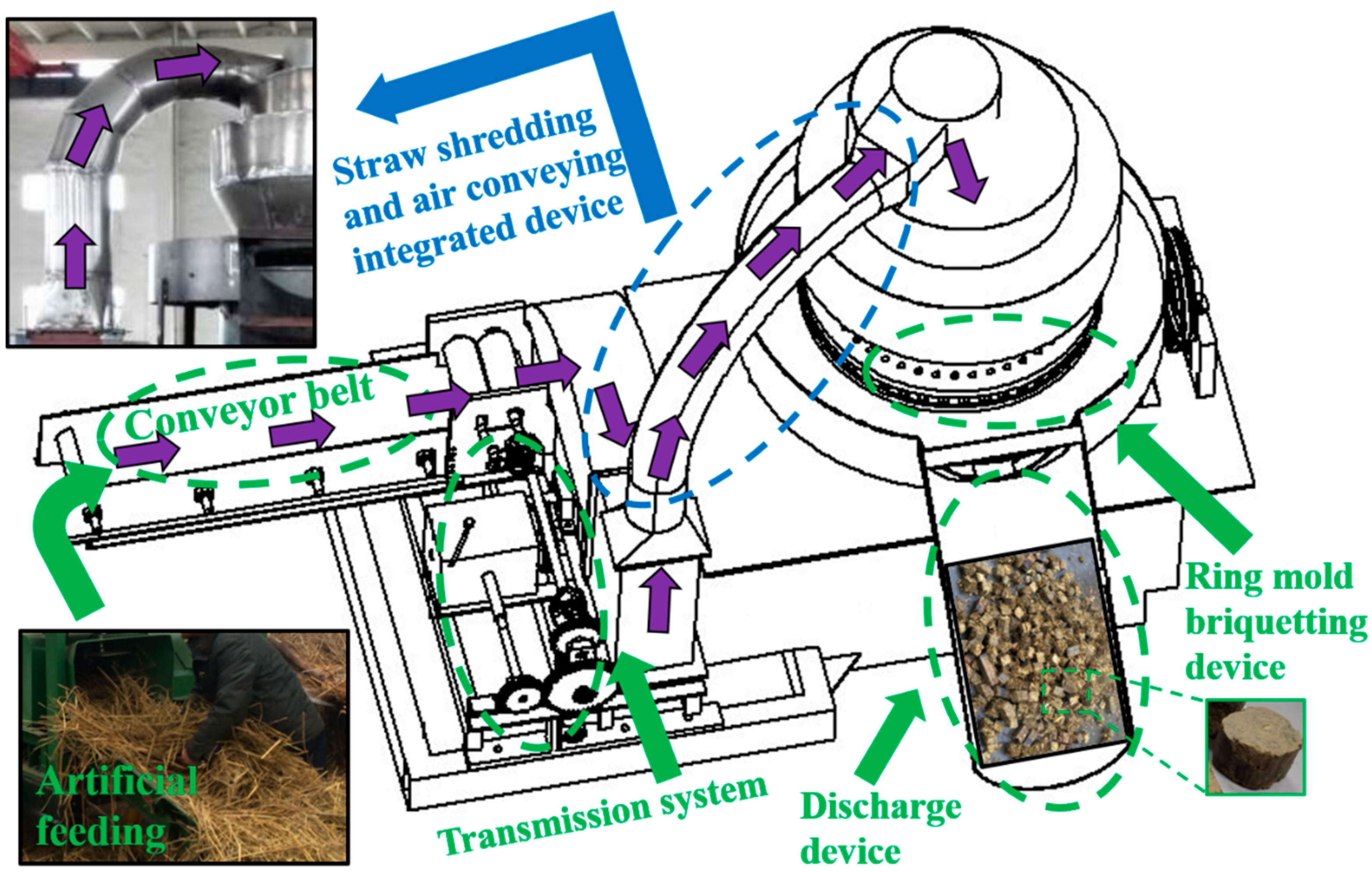
2.1. Structure Description of Straw Briquetting Machine

The movable straw briquetting machine is mainly composed of a straw-shredding and air-conveying integrated device, a ring mold briquetting device, a discharging device and a transmission system, which is shown in Figure 1. The field briquette forming operation is carried out by the tractor pulling the briquetting machine. When the straw briquetting machine is working, the straw is fed from the left side of the figure and placed on the conveyor belt of the straw-shredding and air-conveying integrated device, which is the yellow area in the figure. The straw material is transported to the feeding roller by the conveyor belt, then the straw is compressed and fed into the impeller area by the feeding roller. The rotating cutter and fixed cutter in the impeller area cuts the straw into granules. At the same time, the wind field is generated by the rotation of the impeller blades, and the straw scraps are sent to the upper hopper along the air-conveying cylinder. The straw distribution work is realized by the upper hopper, and the straw moving path is shown by the purple arrow in the figure. After falling from the upper hopper, the straw scraps are compressed into the briquette by the ring mold briquetting device, then extruded from the ring mold hole, and fall onto the rotating disk of the discharging device. The briquettes rotate with the rotating disk to the feeding plate, blocked by the feeding plate, then slide down the hopper and collected, as shown in the orange area in the figure. Through this process, the cluttered and piled straws are briquetted into a form that is convenient for further utilization.

2.2. Experiment on the Air Blowing Speed of Straw

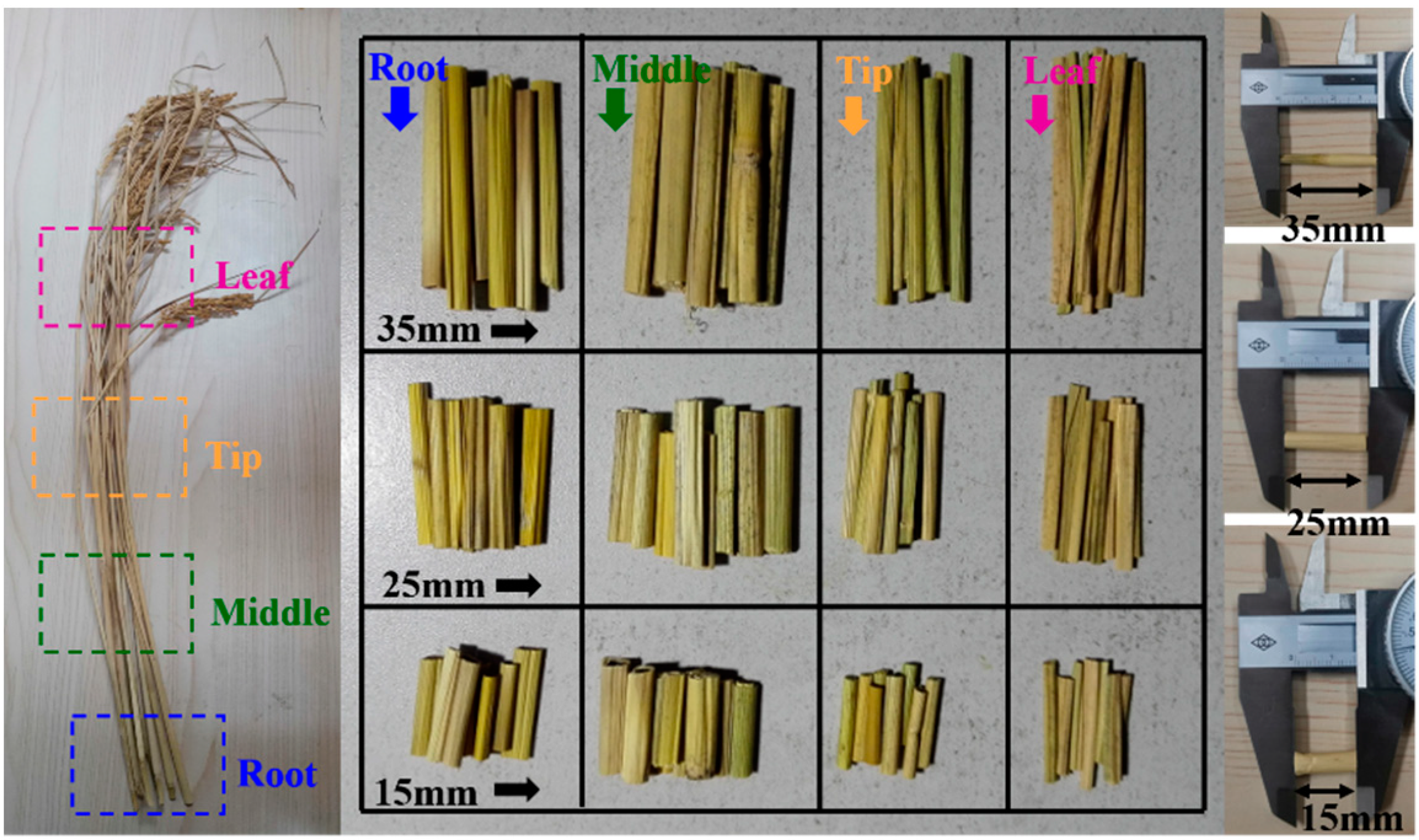
2.2.1. Straw Suspension Experiment Material

Through the straw material suspension speed test, the suspension speed of different parts and different particle sizes of rice straw can be measured, and the minimum air blowing speed of the rice straw can be determined, which provides a basis for the design of the straw-shredding and air-conveying integrated device. The instruments used in the test mainly include: DFPF-25 suspension speed test device (DFPF-25, Jiangsu, China), intelligent pressure anemometer (WindMaster, GILL, Lymington, UK), precision electronic balance (MS32000L, METTLER TOLEDO, Shanghai, China), and a vernier caliper (MNT-150, Shanghai, China). The straw material used in the experiment is Huai Rice No. 5 ear-picking rice straw planted in Huai’an, Jiangsu, China. The suspension speeds of the straw root, middle, tip, and leaf lengths of 15, 25, and 35 mm were measured, respectively. When measuring, the moisture content of the straw was 25~35%, the weight of the straw scrap was 1.5 g. The material is shown in Figure 2.

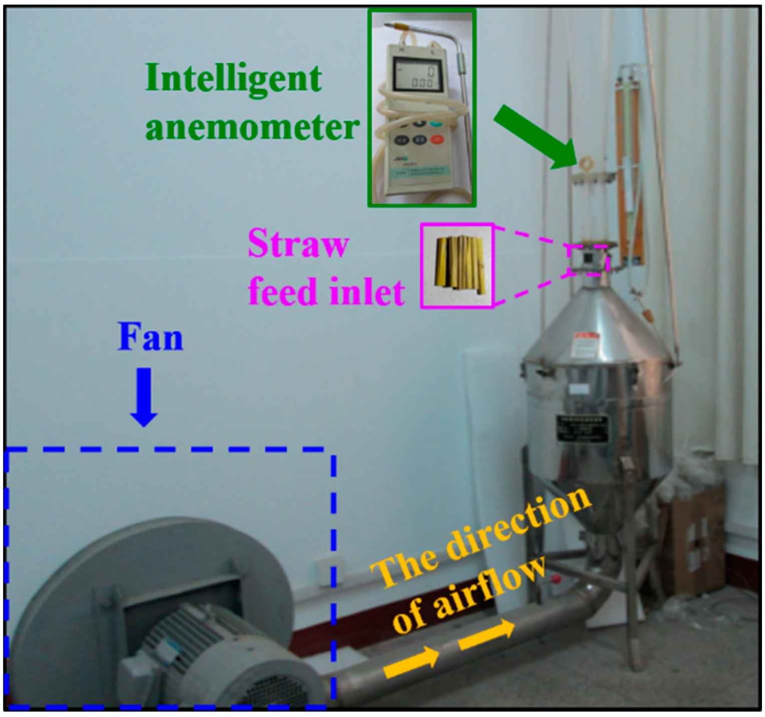
2.2.2. Straw Suspension Experiment Methods

Rice straws of different parts and particle sizes were placed into the DFPF-25 suspension speed test device, the fan was turned on and the speed of the fan was adjusted. When the straw material was in a relatively ideal suspension state, the air velocity V0 of the small end section of the conical tube in the device was measured at the speed measurement point with an intelligent anemometer. V0 is the average value of 4 measuring points in the circumferential direction of the small end section. The structure of the DFPF-25 suspension speed test device is shown in Figure 3.
Since the crushed straw materials are not spherical, a fixed suspension position cannot be obtained in the conical tube. By reading the minimum L value and the maximum L value of the straw material in the conical tube (L is the distance between the suspension position of the straw and the small end section of the tapered tube), according to the Equation (1), the suspension speed range of the straw material was obtained, and then the minimum air blowing speed of the straw material was obtained from the Equation (2).
v i = [ D 0 / ( D 0 + 2 L sin α ) ] 2 v 0
v a = v i × 2 ( 1 + 30 % )
In the above formula, vi is the suspension speed of the straw material; va is the minimum air blowing speed of the straw material; D0 is the minimum end diameter of the tapered tube, which is 81 mm; α is the taper of the tapered tube.

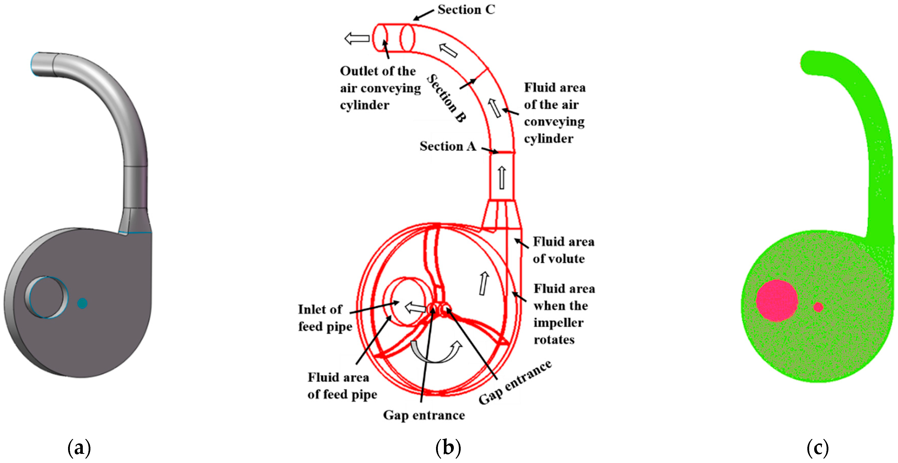
2.3. Establishing Method of the Overall Flow Channel Model

In order to deeply understand the crushed straw material flowing process in the straw-shredding and air-conveying integrated device, the distribution law of the speed field of material in the device was studied [30]. The numerical simulation calculation area of the integrated device were the air flow and the flow space of crushed straw material, which mainly included the volute, the impeller blades, the feed pipe and the air-conveying cylinder. The main parameters of the device calculation area are shown in Table 1.
The corresponding three-dimensional model of the integrated device in Solidworks software was established, then the built three-dimensional model was imported into ICEM software (V15.0, ANSYS Co., Ltd., Pittsburgh, PA, USA) to create the runner model and mesh, as shown in Figure 4c. There were four inlets in the flow path model of the integrated device. The four inlets could be divided into three types. The first type was a feeding pipe inlet, through which air and materials are mixed. Another was two gap inlets that only allow air to enter. The last type was a blower outlet. There were four fluid areas in the flow channel model of the integraited device: the fluid area of the feed pipe, the rotating fluid area of the impeller, the fluid area of the volute, and the fluid area of the air-conveying cylinder. Figure 4 shows the process of establishing the flow channel model of the integrated device. The white arrow in Figure 4b indicates the direction of air flow.
Considering the complexity and actual fluidity of the model, the mesh quality of the model should be improved as much as possible. Therefore, the area with relatively regular structure was divided by a structured grid, the area with more complex structure was divided by an unstructured grid, and the sensitive area was divided by grid refinement. The fluid area of the feeding pipe and the fluid area of the air-conveying cylinder is cylindrical, relatively regular, and was divided by structured mesh, which was a hexahedral mesh. The fluid area of the volute is irregular in structure and was divided by unstructured meshes, which was a tetrahedral mesh. The connection structure of the volute fluid area with the air-conveying cylinder was a sensitive fluid area, and mesh refinement processing was performed. The overall flow channel grid of the integrated device was divided into 2,007,505, the number of nodes was 348,621, and the quality of the grid was greater than 0.4.
Before the simulation analysis, it is necessary to set the boundary of the flow channel model of the straw-shredding and air-conveying integrated device in FLUENT software (V20.0, ANSYS Ltd., Pittsburgh, PA, USA). All the surfaces of the feed pipe, volute, impeller, and air-conveying cylinder were defined as walls. Defined the contact surfaces between the inlet of the feed pipe and the volute. The outlet of the volute and the inlet of the straight feed pipe of the air-conveying cylinder, the impeller and the volute as the interface surface, which was used to connect four fluid areas.
The multiple reference frame method was used to simulate the quasi-steady flow field in the integrated device. The rotating speed of the impeller rotation area was 630 r/min, which was the rotation area, set as the rotating reference coordinate system. Other areas in the integrated device were static domains, which were set as a static reference coordinate system. The flow fields in the dynamic and static domains were calculated in their respective coordinate systems, and the flow fields were coupled through coordinate system conversion to obtain the quasi-steady simulation results of the flow field. The inlet of the feed pipe and the two gap inlets were set as velocity inlet boundary conditions. The air velocity at the inlet of the feed pipe is 2 m/s, the crushed straw material velocity is 0.8 m/s, and the material volume fraction is 0.18. Only air enters through the openings of the two gaps, the air velocity was 1 m/s. The material speed and volume fraction were set to 0. The outlet of the air delivery cylinder was set as a pressure outlet.
The Eulerian model was selected for the numerical calculation of the gas–solid two-phase flow in the integrated device, and the finite volume method was used to discrete the control equation. The turbulence model selected the standard k-ε model and used the standard wall function. The speed and pressure coupling mode selected the Phase Coupled SIMPLE format, and the discrete format of each control equation was set to the second-order upwind style. Due to the irregular structure of the integrated device, and the speed of crushed straw material in the impeller volute area and the air-conveying cylinder area was very different. In order to facilitate observation and research, the impeller volute area and the air-conveying cylinder were separated and analyzed.

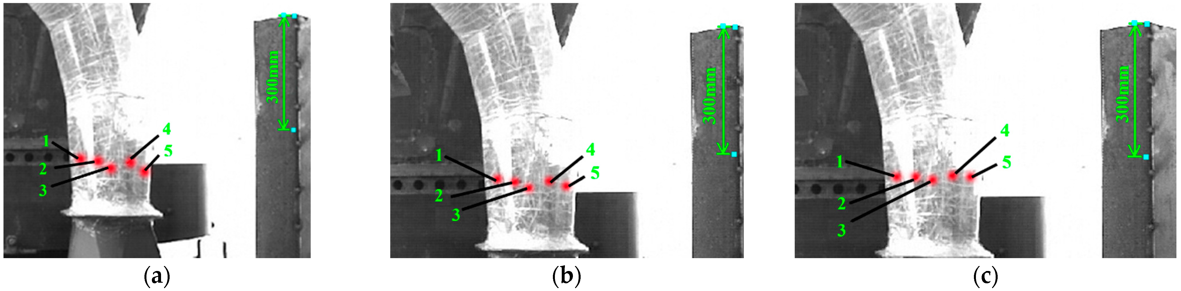
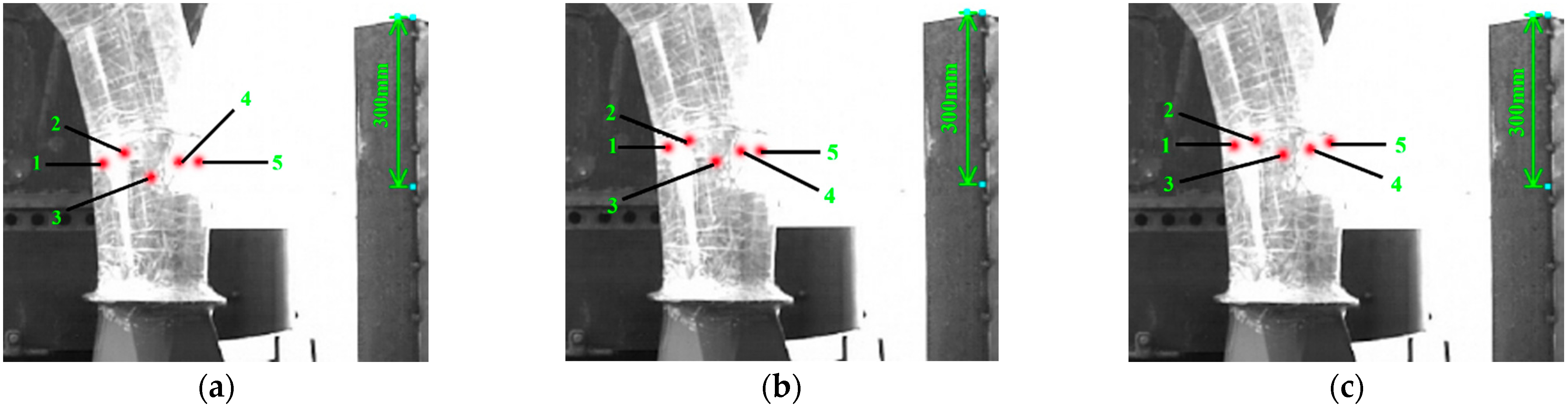
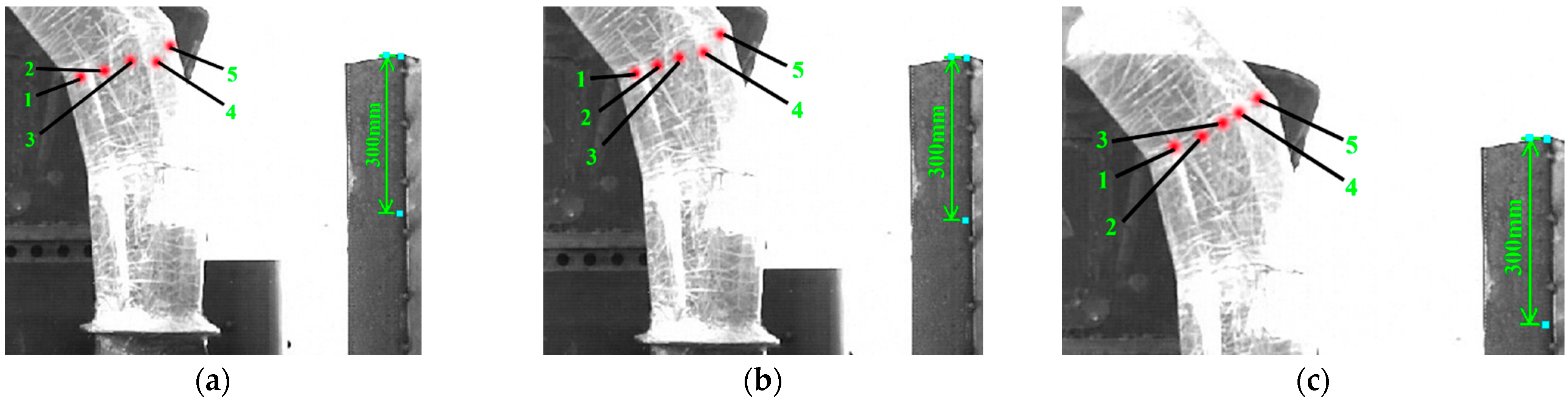
2.4. High-Speed Photography Experiment of Rice Straw Suspension Speed

In order to verify the reliability of the motion law obtained by simulation, the field high-speed photography experiment of rice straw suspension speed was carried out. The rice stalks were fully air-dried during the experiment; the moisture content was about 30%. The test equipment mainly included the mobile straw briquetting machine (9SM-YJ-2000, HAIAN SHIMING MACHINERY MANUFACTURING Co., Ltd., Jiangsu, China), high-speed camera (i-SPEED 3, OLYMPUS Co., Ltd., Miyazaki Prefecture, Japan), transparent air-conveying cylinder. The maximum shooting speed of the high-speed camera was 10,000 frames per second, and the maximum capacity of the 2.5 G images could be collected. This experiment used a shooting speed of 2000 frames per second. In order to facilitate the photographing and observation, the air blow cylinder was made transparent, according to the actual size using PET material. The high-speed camera test site layout is shown in Figure 5. The high-speed camera was facing the air-conveying cylinder, and the shooting distance was 2 m. Since the high-speed camera shoots a two-dimensional plane picture, each section was regarded as a projected line.
During the test, the high-speed camera was used to track and record the movement process of the crushed straw material in the air-conveying cylinder area. After the test, the pictures were repeatedly compared, observed, and analyzed by the i-SPEED software (i-SPEED 3, OLYMPUS Co., Tokyo, Japan). In order to facilitate observation, calculation, and analysis, only two-dimensional plane changes were considered, and a part of the straw was dyed in different colors before the experiment. During each observation and analysis, the position of the centroid of the crushed straw material at each moment was recorded. The change of the overall displacement with the displacement in the x and y directions was characterized to determine the dynamic change process and movement trajectory of the crushed straw material. The moving speed of crushed straw material at each radial section of the air-conveying cylinder was calculated through Δ v = Δ L / Δ t .
In order to simplify the difficulty of picture analysis, when observing and analyzing the taken pictures, the picture time interval was selected to be 0.002 s. The movement process of the five sections of crushed straw material near the A section was captured as well as in the B section of the feed straight pipe and the C section of the elbow pipe in the figure. The moving distance ΔL of each segment of crushed straw material in two adjacent frames was measured. The moving speed Vn of each segment of crushed straw material was calculated by Vn = ΔL/0.002. By calculating the average value, the average moving speed of each section of crushed straw material in each section was obtained.

2.5. Test Verification of the Improved Whole Straw Briquetting Machine

On the basis of the improvement of straw-shredding and air-conveying integrated device, the whole machine performance research was carried out. The straw briquetting productivity and briquetting density were used as evaluation indicators to test the whole machine’s performance. The briquet was produced on the 9SM-YJ-2000 mobile straw briquetting machine. The feed roller speed was 125.84 r/min, the impeller speed was 776.05 r/min, the ring die spindle speed was 169.16 r/min, the straw moisture content was about 30%, and the mold roll gap was 3 mm. Each experiment was completed in groups. In order to facilitate the control of the spindle speed of the ring die, it was driven by a motor and pulled by a tractor to the outdoors for testing. The transmission ratio could be changed by changing the size of the sprocket on the feeding roller shaft to achieve the feeding roller speed required for each group of tests. The pulley transmission ratio could be adjusted by changing the size of the pulley on the impeller shaft to achieve the impeller speed required for each group of tests. The speed of the motor was adjusted by controlling the frequency converter to obtain the spindle speed of the ring die required for each group of tests. The briquetting test is shown in Figure 6.

3. Results and Discussion

3.1. Analysis of the Experiment Results of the Straw Materials’ Suspension Speed

Through the straw material suspension speed test, the suspension speed of different parts and different particle sizes of rice straw can be measured, and the minimum air blowing speed of the rice straw can be determined. The results of the suspension speed test of straw materials are shown in Table 2 below.
As shown in Table 1, when the particle size of straw leaf is 15 mm, the minimum air blowing speed required is the smallest, which is 9.39 m/s; when the particle size of straw tip is 35 mm, the minimum air blowing speed required is the largest, which is 16.28 m/s. Because the straw leaf is light in weight and has a large windward area, when the particle length is 15 mm, the weight is the lightest and the required air blowing speed is the smallest. The windward area of the straw tip is similar to the root and middle part of the straw at the same size particles, but the quality of the straw is larger, therefore the minimum air blowing speed required is larger.

3.2. Analysis of the Simulation Results of the Overall Flow Channel Model

The influencing factors of the straw-shredding and air-conveying integrated device are impeller speed, the number of blades, and blade pitch. The setup of these factors was varied in the simulation to investigate how these factors affect the flow of straw inside the device.

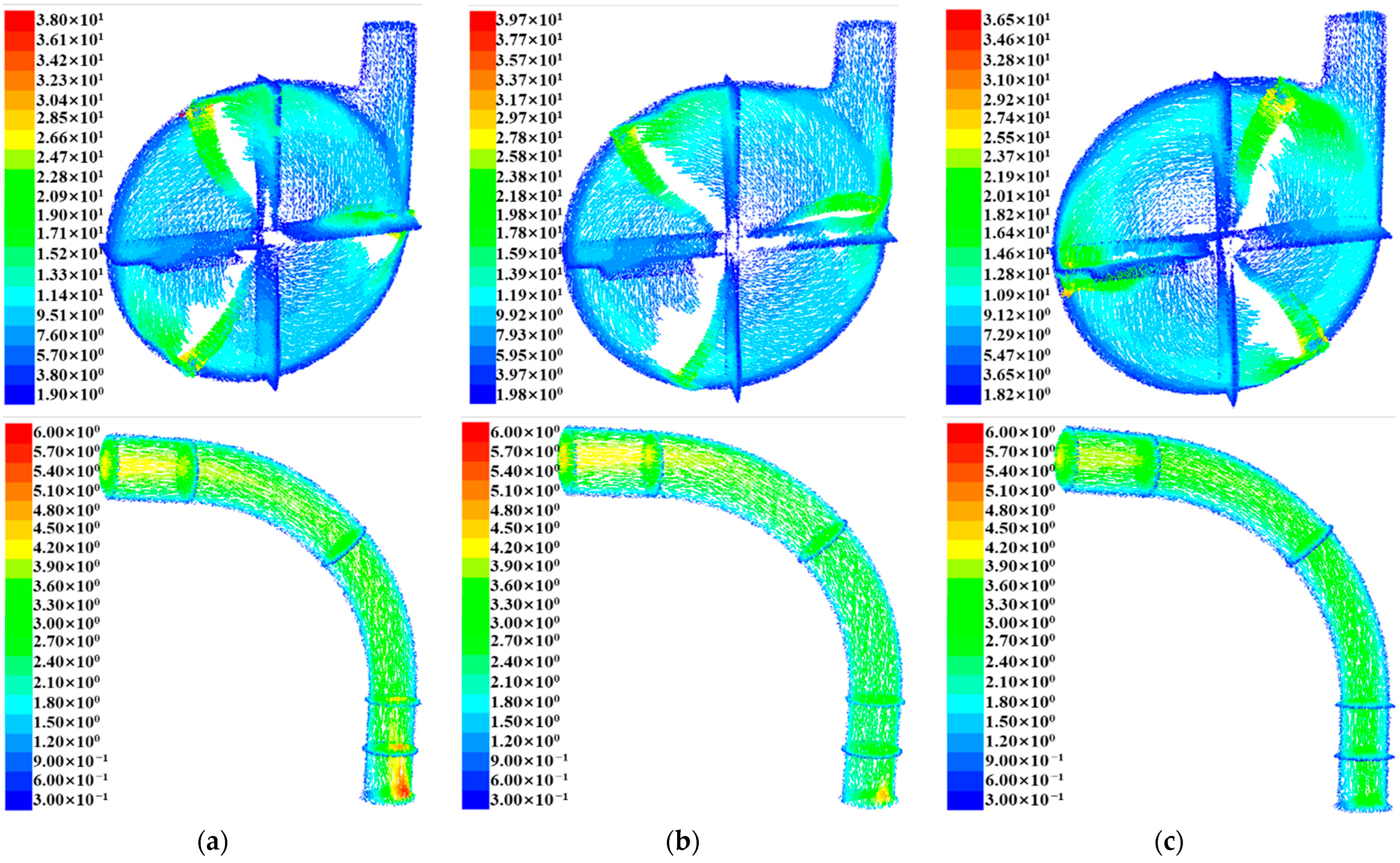
3.2.1. Influence of Impeller Speed

The parameters were kept unchanged: the number of blades was three, the blade inclination angle was 0°, and the curvature radius of the air duct elbow was 700 mm. When the impeller speed was 450 r/min, 630 r/min, and 810 r/min, the gas–solid two-phase flow field in the integrated device was calculated, respectively. By comparing and analyzing the vector diagrams of the crushed straw material speed in the device at three rotation speeds, the influence of the impeller speed on the material flow in the device was determined. The velocity vector diagram of the crushed straw material in the integrated device under three different impeller rotations is shown in Figure 7.
It can be seen from Figure 7 that when the impeller speed was 450 r/min, because the impeller speed was low, the energy obtained by the crushed straw material was smaller when it left the blades. The speed of the crushed straw material in the impeller volute area and the air-conveying cylinder area were both low, and the speed dropped quickly, which was not conducive to the throwing of crushed straw material. When the impeller speed was 810 r/min, because the impeller speed was too fast, the crushed straw material and the leaves was separated greatly, so that the moving direction of the crushed straw material changed near the volute outlet and the air feed tube inlet. The materials collided with the pipe wall many times, and the energy was rapidly lost. The speed at the volute outlet and the straight pipe of the air-conveying tube was reduced sharply, so that the maximum speed at which the materials were thrown out of the air-conveying cylinder was reduced to 4.0~4.5 m/s. Compared with the other two working conditions, the movement of the crushed straw material in the impeller volute area was more regular when the impeller speed was 630 r/min. The scrap material had a uniform speed in the air-conveying cylinder, and the high-speed area was large. The maximum speed at which the materials were thrown out of the air-conveying cylinder was 4.2~4.5 m/s. It was able to effectively throw out the crushed straw material.

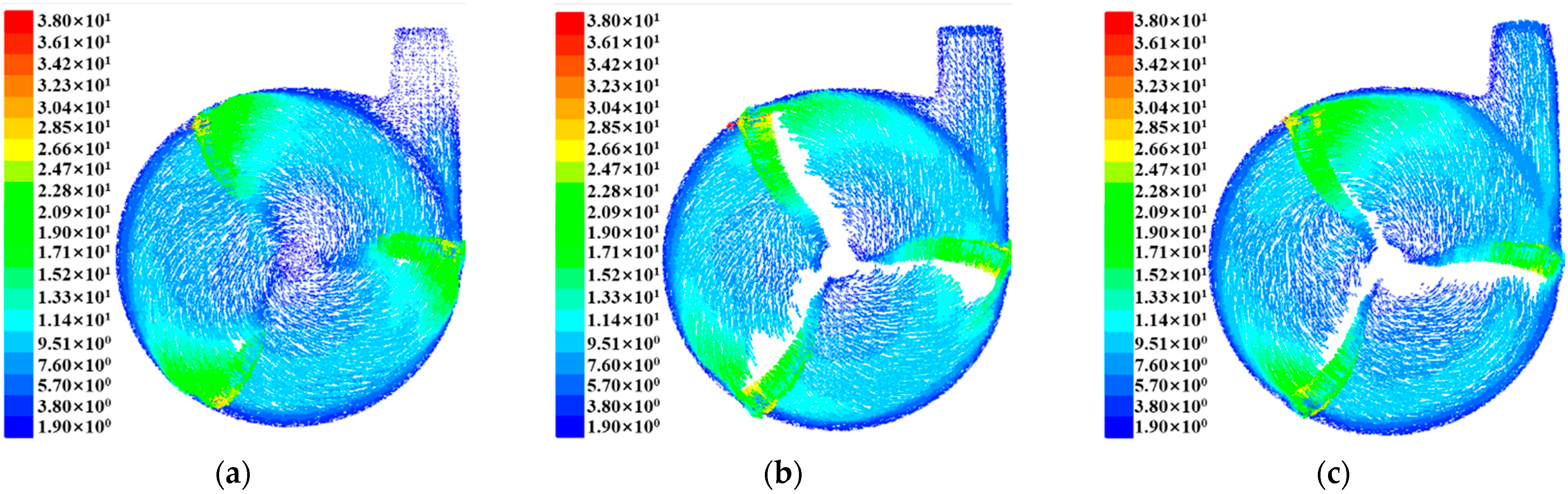
3.2.2. Effect of the Number of Blades

The parameters were kept unchanged, the impeller speed was 630 r/min, the blade inclination angle was 0°, and the curvature radius of the air duct elbow was 700 mm. When the number of blades was three, four, and five, the gas–solid two-phase flow field in the integrated device was calculated, respectively. By comparing and analyzing the vector diagrams of the crushed straw material speed in the device at three kinds of blades, the influence of the blades’ number on the material flow in the device was determined. The velocity vector diagram of the crushed straw material in the integrated device under three different blades’ number is shown in Figure 8.
As shown in Figure 8, when the number of blades were four and five, because of the large number of blades, the blades frequently beat the material, making the flow field flow more unstable, the material collided with the wall of the volute frequently, and the energy loss was greater. In the impeller volute area, the blades and the crushed straw material were severely separated, and a lot of turbulence, backflow and secondary flow occurred. In the air-conveying cylinder area, the material speed was lower, and the high-speed area was smaller. The maximum speed at which the materials were thrown out of the air-conveying cylinder was 3.9~4.2 m/s. Compared with the other two working conditions, the flow field flow was more stable and regular, and the high-speed area was larger when the number of blades was three. The maximum speed at which the materials were thrown out of the air-conveying cylinder was 4.2~4.5 m/s. At this time, the ability to throw crushed straw material was stronger, and the efficiency was higher.

3.2.3. Effect of Blade Pitch

The parameters were kept unchanged: the impeller speed was 630 r/min, the number of blades was 3, and the radius of the curvature of the air duct elbow was 700 mm. When the blade angle was 0°, 15° backward, 15° forward, the gas–solid two-phase flow field in the integrated device was calculated, respectively. By comparing and analyzing the vector diagrams of the crushed straw material speed in the device at three blade angles, the influence of the blade angle on the material flow in the device was determined. The velocity vector diagram of the crushed straw material in the integrated device under three different blade inclination angles is shown in Figure 9.
It can be seen from Figure 9, when the blade tilted 15° backward and 15° forward, the speed gradient of the crushed straw material was smaller, and the distribution was more uniform compared with the blade inclination angle of 0° in the impeller volute area. Because of the backward tilt of the blades, the rotation diameter of the blades became relatively larger, and the linear velocity at the end of the blade became larger, which made the speed of the crushed straw material larger. When the blade was tilted backward by 15°, the maximum rotation speed was 39.7 m/s, and there was a higher speed zone at the volute discharge port. When the blade inclination angle was 0°, the rotation speed was next to 38 m/s. The minimum rotation speed was 36.5 m/s when the blade was tilted forward by 15°. The backward or forward tilt of the blades concentrated the crushed straw material at the volute discharge port, which was more uniform and efficient.
In the air-conveying cylinder area, when the blades were tilted forward by 15°, the speed of the crushed straw material was low, which was not conducive to throwing. When the blade inclination angle was 0°, the speed of material at the inlet and outlet of the air-conveying cylinder was higher, but the speed distribution was uneven, and the high-speed area was small. Compared with the other two working conditions, the material flowed more evenly, and the high-speed area was larger when the blades were tilted back by 15°. The maximum speed of the material at the discharge port was 4.5~4.8 m/s with higher efficiency.

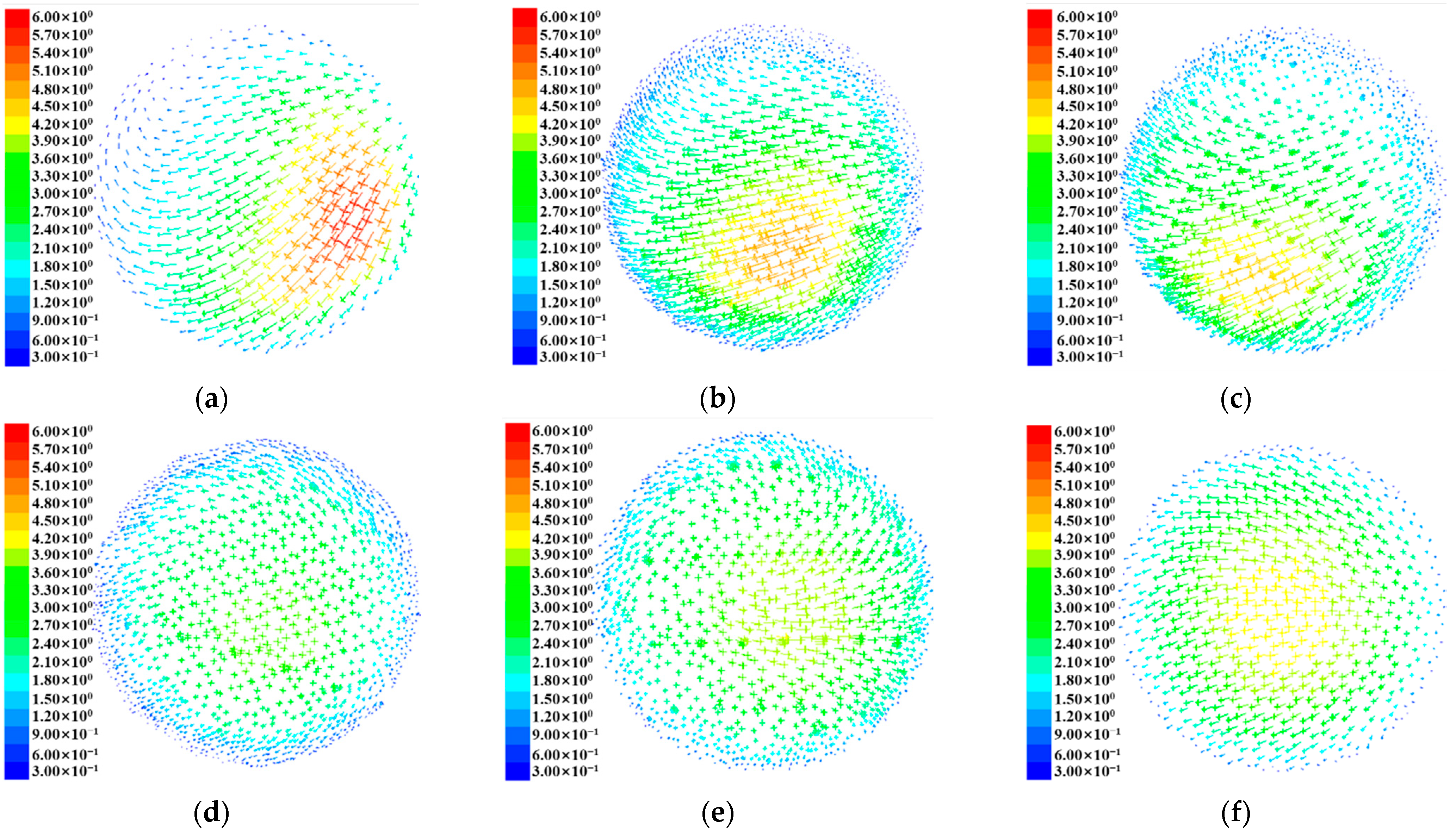
3.3. Simulation Results and Discussion of the Flow Field in the Integrated Device

The fluid movement law in the device was studied by analyzing the flow field pressure distribution and flow field velocity distribution inside the device.

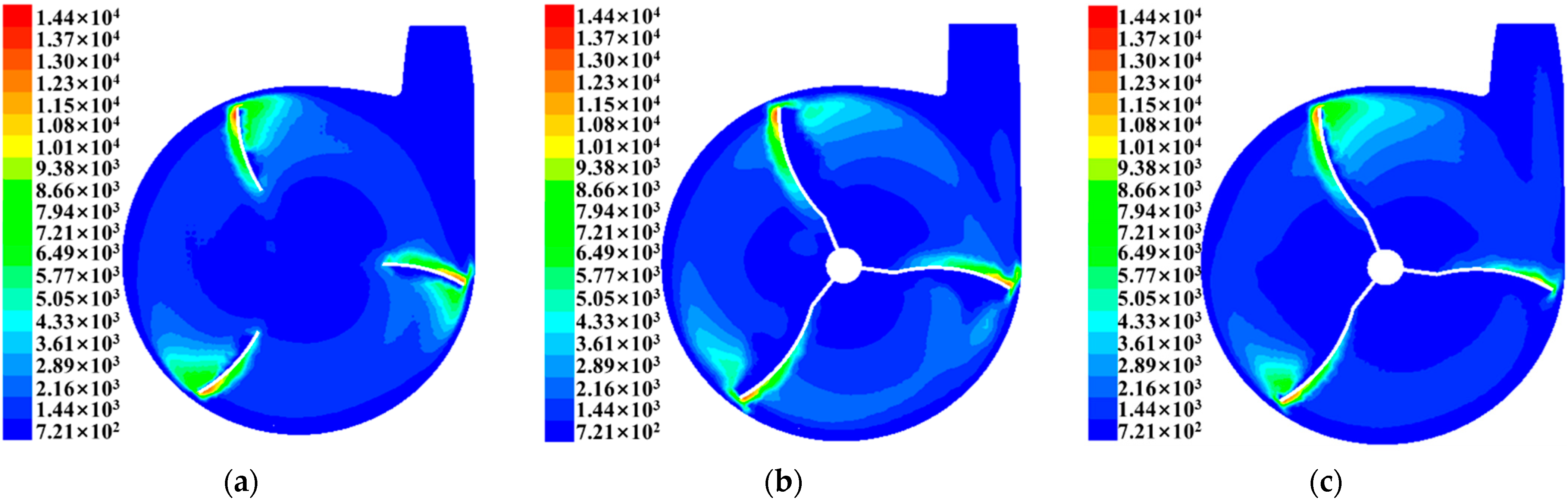
3.3.1. Flow Field Pressure Distribution

When the flow field pressure distribution was investigated, the mixed static pressure of the gas–solid two-phase, the dynamic pressure of crushed straw material phase, and the total pressure cloud diagram of the crushed straw material phase were simulated and studied, respectively. The pressure cloud diagram in the device is shown in Figure 10.
It can be seen from Figure 10: (1) The distribution trend of the mixed static pressure cloud diagram of the gas–solid two-phase was roughly the same as the dynamic pressure and total pressure cloud diagram of the crushed straw material phase. In the impeller rotation area, the static pressure, dynamic pressure, and total pressure gradually increased along the radial direction, and the pressure value reached the maximum at the end of the impeller blade. When the impeller rotated at high speed, it collided with the nearby crushed straw material, driving it to move at a high speed, which produced a large centrifugal force and Coriolis force [31]. As the radial distance increased, the linear velocity of the blade increased, the centrifugal force and Coriolis force gradually increased and reached the maximum at the end of the impeller blade.
(2) In the cloud diagram of the phase dynamic pressure and total pressure of the crushed straw material, there was an obvious high-pressure area on the convex surface of each blade and an obvious low-pressure area on the concave surface of each blade. Because the impeller rotated in a counterclockwise direction and the convex surface of the blade collided with the crushed straw material, this resulted in greater pressure. Due to the high-speed rotation of the impeller, the speed of the impeller was faster than that of the straw material, which separated the concave surface of the blade from the material, resulting in a lower concave surface pressure. In addition, there was an obvious higher-pressure area near the low-pressure area at the end of the concave surface of the blade. Because the centrifugal force and Coriolis force near the low-pressure area at the end of the blade were larger, the pressure generated was greater.
(3) Because the linear velocity at the end of the impeller blade was faster, the centrifugal force generated was greater, which made the crushed straw material faster, and the dynamic pressure and total pressure were also higher [32]. The pressure on the right side of the discharge port of the volute was obviously higher than that on the left side.
(4) Because there was obvious backflow and secondary flow near the impeller rotation center, some crushed straw materials were concentrated in this area and moved at a low speed, resulting in lower pressure. There was a large area of low pressure in the rotation center of the impeller volute.
The thickness direction of the impeller was set to the Y-axis. In order to further study the characteristics of the change in the pressure distribution of the crushed straw material phase in the impeller volute region along the Y-axis, a dynamic pressure cloud diagram of the crushed straw material of different sections along the direction of the Y-axis was created, as shown in Figure 11.
Since the middle section of the front wall of the volute was greatly affected by the feed inlet, the phase movement of the crushed straw material was uneven. It can be seen from Figure 11 that the dynamic pressure of the crushed straw material from the middle section to the rear wall of the volute was more even than the dynamic pressure distribution from the middle section to the front wall of the volute. Compared with Figure 11b and Figure 11c, there was an obvious high dynamic pressure area near the concave surface of the blade at the end of the blade near the discharge port of the volute in Figure 11a. Because the impeller blade structure was in the shape of a knife when viewed from the top, the crushed straw material on the side close to the rear wall of the volute was able to flow fully, and a higher dynamic pressure was obtained, which was beneficial to the throwing of the straw material.

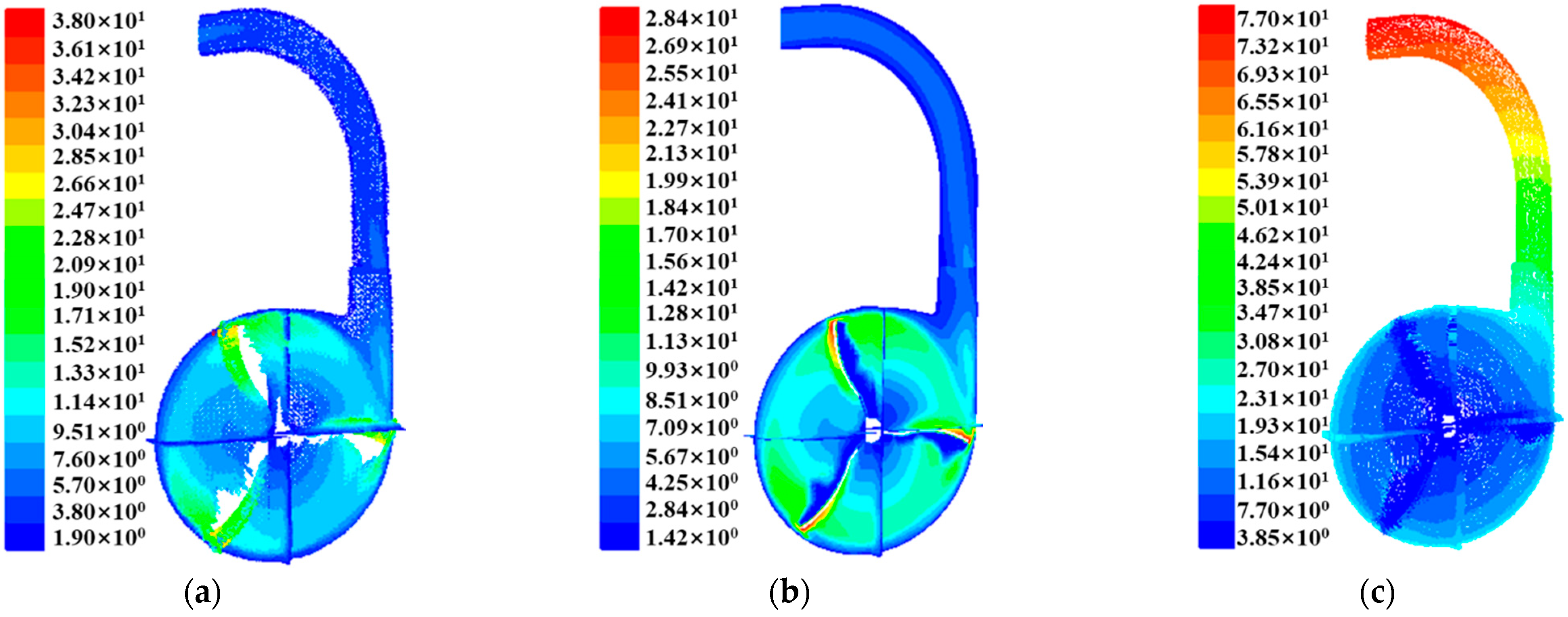
3.3.2. Flow Field Velocity Distribution

Velocity field is another important feature of fluid flow. In order to further understand the complex flow process of the crushed straw material in the device, this paper analyzed the velocity distribution law in the straw-shredding and air-conveying integrated device. Figure 12 is a diagram of the velocity distribution in the integrated device.
It can be seen from Figure 12: (1) The velocity distribution of the crushed straw material phase in the impeller volute area was uneven, and there were a large number of eddies, backflows, secondary flows and irregular flows. The vortex was mainly caused by backflow and secondary flow. The backflow and secondary flow were mainly affected by the impeller blade structure, the size of the volute discharge port, and the impeller speed. The irregular flow was mainly caused by the flapping of the impeller blades and the collision with the wall of the volute.
(2) It can be seen from Figure 12a that there were obvious blank areas near the concave surface of each impeller blade. Because the impeller rotated at a high speed, and the speed of the impeller was faster than that of the crushed straw material, which caused the concave surface of the blade to separate from the crushed straw material.
(3) The speed was relatively fast at the right side of the feed straight pipe on the air-conveying cylinder and the discharge port. The end of the impeller blade threw the straw material upward with a high speed at the volute discharge port, which made the speed at the right side of the inlet straight pipe on the air-conveying tube higher. Since the outlet section of the air-conveying cylinder was a straight pipe, the outlet of the air-conveying cylinder had a faster speed area. When the crushed straw materials moved to the discharge port, there was no centrifugal force. Under the action of wind and its own gravity, the speed of material increased. However, this also caused a small amount of eddy currents at the junction of the elbow pipe of the air-conveying cylinder and the straight discharge pipe.
(4) It can be seen from Figure 12c that the relative speed between the crushed straw material phase and the air phase was slower in the impeller volute area. However, in the area of the air-conveying cylinder, the relative velocity of the crushed straw material phase and the air phase gradually increased from the straight pipe of the air-conveying cylinder to the discharge port. Because the crushed straw material had slowed down sharply after the crushed straw material was thrown into the air-conveying cylinder area because of the weight of the crushed straw material, the collision with each other, and the collision and friction between the straw material and the wall of the air-conveying cylinder. When the materials enter the elbow area, they were separated from the air under the action of centrifugal force.
The thickness direction of the impeller was set to the Y-axis in order to further study the characteristics of the change in the velocity distribution of the crushed straw material phase in the impeller volute region along the Y-axis. A velocity vector diagram of the crushed straw material phase in the impeller volute region along the Y-axis was created, as shown in Figure 13.
It can be seen from Figure 13: The flow of the crushed straw material in the volute area of the impeller was more complicated. The velocity vector distribution on each cross-section was quite different. The velocity of the crushed straw material changed rapidly, and there were serious vortices. Figure 13a was a cross-section close to the back wall of the volute. Compared with Figure 13b and Figure 13c, there was no obvious blank area at the concave surface of each impeller blade in Figure 13a because the impeller blade structure looks like a knife from a top view. When the impeller rotated at a high speed, the speed of the impeller was faster than that of the crushed straw material, so that the concave surface of the blade near the front wall of the volute separated from the straw material. However, the crushed straw material on the side close to the rear wall of the volute was not blocked by the blades and could obtain sufficient flow, which was beneficial to the throwing of the straw material.
Figure 14 compared the velocity vectors on the front and back walls of the volute. The crushed straw material on the front wall and the rear wall of the volute were slow. The straw materials on the front wall were not flowing smoothly, there were a lot of eddy currents and irregular flows. For that reason, the straw material at the front and rear walls of the volute were not subjected to the forward flapping force and wind force of the impeller blades, so the crushed straw material speed was relatively low. The straw materials on the front wall were mainly affected by the material inlet and flowed non-smoothly.
In order to further study the change characteristics of the velocity distribution of crushed straw material phase in the air-conveying cylinder area, a radial section of each key position in the air-conveying cylinder area was created along the center line of the air-conveying drum. The velocity distribution characteristics of the crushed straw material phase in the middle section and the radial section of the air-conveying cylinder were analyzed.
Figure 15 is the velocity vector diagram of each key radial section of the air-conveying cylinder. The direction from left to right of each section was the direction from the inner wall of the air-conveying cylinder to the outer wall of the cylinder. It can be seen from Figure 15 that: (1) From the inlet of the straight feeding pipe to the outlet of the straight feeding pipe, the area with a faster crushed straw material speed gradually moved from the right to the left. At the same time, the maximum speed dropped from 5.7~6.0 m/s to 4.5~4.8 m/s. The reason for the large decrease in speed was that the materials collided with the inner tube wall of the air-conveying cylinder when the straw material moved from the right to the left, resulting in a greater loss of energy.
(2) From the outlet of the straight feeding pipe to the middle section of the elbow, the area with a faster crushed straw material velocity gradually moved from the left side to the middle part. At the same time, the maximum speed dropped from 4.5~4.8 m/s to 3.6~3.9 m/s. The reason for the large decrease in speed was that the material collided with the outer wall of the elbow when the straw material moved upward, resulting in a greater loss of energy. Because the materials slid along the outer wall of the elbow under the combined action of wind and centrifugal force, the resistance was relatively large, so that the velocity near the wall of the air duct was relatively low. Therefore, the area where the crushed straw material was faster had gradually moved from the left to the middle.
(3) From the middle section of the elbow pipe to the outlet of the straight pipe, the position of the area where the speed of the straw material in the middle part became faster and faster. At the same time, the maximum speed increased from 3.6~3.9 m/s to 4.5~4.8 m/s. After the straw material moved to this position, there was no centrifugal force and the speed increased under the action of wind and gravity.

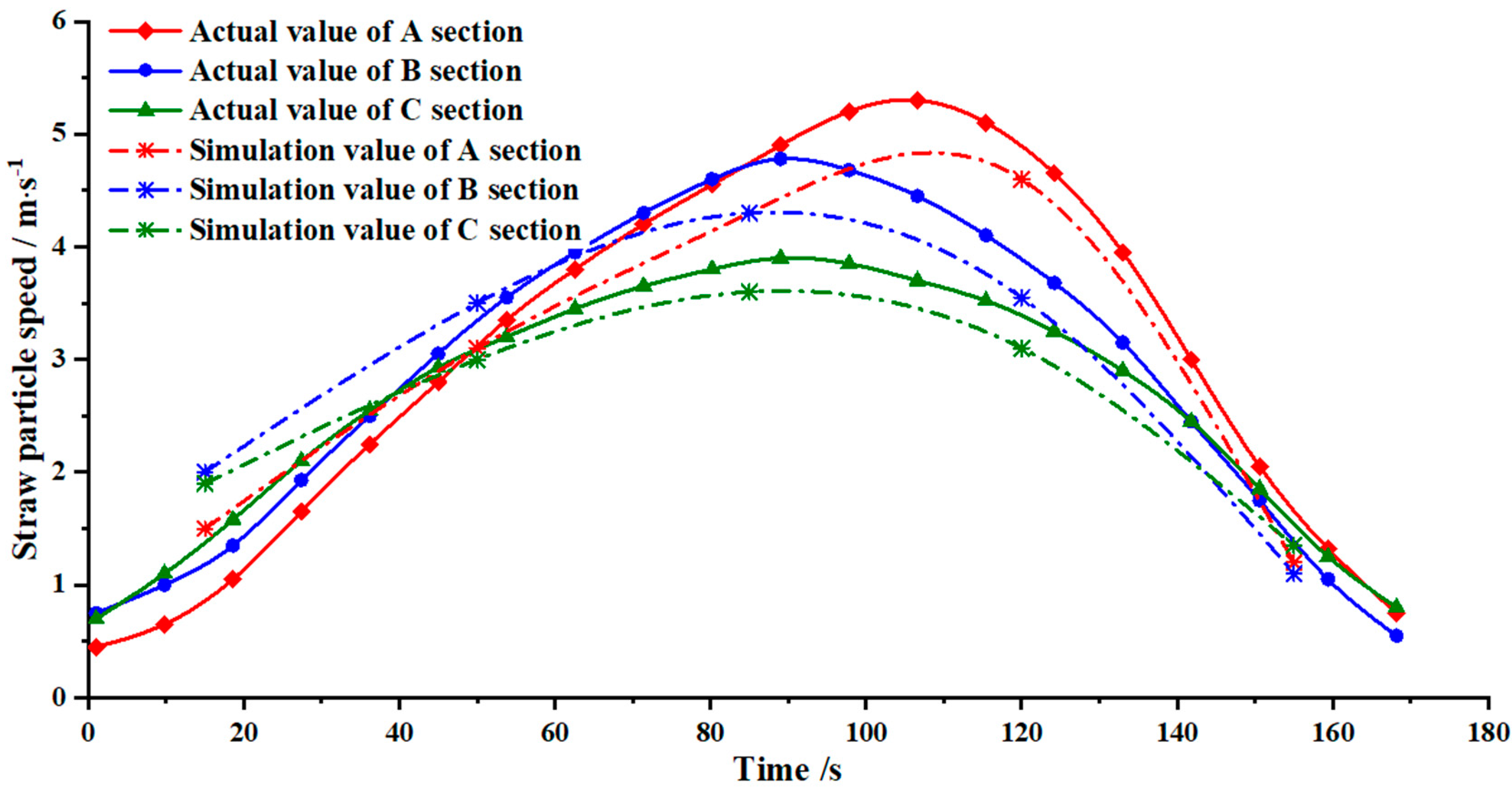
3.4. High-Speed Photography Experiment Results and Discussion

The speed simulation results of the crushed straw material phase in each radial section of the air-conveying cylinder area were comparatively verified by high-speed photography test of the rice straw suspension speed. In order to facilitate the calculation and drawing of the change curve of the crushed straw material speed with the movement time and displacement, it was necessary to calibrate the size of the taken pictures. Because the vision of each picture taken by high-speed camera was determined, the coordinates of each picture were also consistent. Therefore, the green line D with the actual size of 300 mm in the upper right corner of the baffle in the picture was taken as the reference object.
Figure 16, Figure 17 and Figure 18, respectively, show the movement process of the crushed straw material of the A section, B section, and C section taken by high-speed camera. Five obvious points where crushed straw scraps appeared were selected and numbered as 1, 2, 3, 4, and 5. Through the high-speed camera test, it can be seen that the crushed straw materials moved upwards in a changing posture under the action of airflow and centrifugal force after entering the air-conveying cylinder. Some of the straw materials entered the upper section of the straight feed pipe and collided with the inner wall of the straight pipe to be bounced away and continued to move upward under the action of the airflow. In addition, some straw materials entered the elbow and collided with the outer wall of the elbow and slid upwards along the outer wall under the action of airflow and centrifugal force. When they moved to the middle section of the elbow, most of the straw materials slid upward along the outer wall of the elbow against the frictional force. After the straw materials entered the straight discharge pipe from the discharge port of the elbow, due to the absence of centrifugal force, the materials were thrown obliquely downwards from the air duct under the action of its own gravity and wind. Through Figure 16, Figure 17 and Figure 18, the movement speed of the crushed straw material at the A section, B section, and C section can be obtained. Compared with the simulation data of the straw material average velocity at each section extracted from the post-processing of the FLUENT software to verify the reliability of the CFD numerical simulation. The result is shown in Figure 19.
As shown in Figure 19, it can be seen that the peak crushed straw material velocity at section A was 4.35~5.30 m/s, which appeared between 0.105~0.125 m in the transverse position of the section. The peak stalk material velocity at section B was 4.30~4.80 m/s, which appeared between 0.08~0.105 m in the transverse position of the section. The peak stalk material velocity at section C was 3.60~3.90 m/s, which appeared between 0.085~0.10 m in the transverse position of the section. From the A section to the B section and then to the C section, the speed of the straw materials decreased greatly. The reason of this is that the straw materials collided with the inner wall of the straight pipe when they moved to the B section and collided with the outer wall of the elbow when they moved to the C section. This caused more the energy loss of the straw materials, resulting in a greater reduction in speed. The change trend of the straw scrap speed measured by a high-speed camera was basically the same as the simulation value. The A section straw material velocity measured by high-speed camera was 1.20~4.60 m/s, and the simulation value was 0.45~5.30 m/s. The B section straw material velocity measured by high-speed camera was 1.10~4.30 m/s, and the simulation value was 0.55~4.80 m/s. The C section straw materials velocity measured by high-speed camera was 1.35~3.60 m/s, and the simulation value was 0.70~3.90 m/s. The data in the left figure, which were measured by high-speed camera, were too large because the high-speed camera only observed one side of the air-conveying cylinder, and it measured the maximum speed of the straw materials. The data obtained by the simulation on the right were too large because the device was simplified during the simulation, and the air leakage and friction between the material and the air duct wall were not considered.

3.5. Results of Briquetting Production on the Whole Machine

The production test of the whole machine was carried out on the basis of the improved straw-shredding and air-conveying integrated device. The density of the briquettes and straw briquetting productivity were measured. The results were compared with the density of the briquettes and straw briquetting productivity before optimization. The production test was repeated three times.
The cylindrical straw briquettes produced were obtained under different conditions, cut into lengths of 20 mm with a knife, and stored in sealed bags. One of the sections was taken for density measurement. A certain amount of water was placed in a 250 mL measuring cup and the parameter V1 of the existing water amount was recorded. The pressure block was placed into the zero-adjusted electronic balance to measure the mass M, then it was taken out and put into the measuring cup. The water volume parameter, V2, when the briquette is completely immersed in water was recorded. Thus, the density of the briquettes can be obtained by Equation (3):
ρ = M V 2 V 1
The calculation of the increase rate of production is shown in Equation (4):
f = E e E × 100 %
The results are shown in Table 3.
As shown in Table 3, the measured values of briquette density before optimization were 1.085 g·cm−3, 1.151 g·cm−3, and 1.127 g·cm−3, respectively, with an average value of 1.121 g·cm−3. After optimization, the actual measured values of the three tests were 1.119 g·cm−3, 1.195 g·cm−3, and 1.140 g·cm−3, with an average value of 1.151 g·cm−3. The increase rate of briquette density was 3.04%, 3.64%, and 1.14%, respectively, with an average value of 2.61%. The measured values of briquette production before optimization were 1061, 1136, and 1077, respectively, with an average value of 1091. After optimization, the actual measured values of the three tests were 1098, 1154, and 1106, with an average value of 1119. The increase rate of briquette productivity was 3.37%, 1.56%, and 2.62%, respectively, with an average value of 2.52%.

4. Conclusions

There is a lack of scientific research on the structural and operating parameters of the straw-shredding and air-conveying integrated device, which leads to low efficiency in throwing straw scraps into the ring mold briquetting device. The CFD simulation of the gas–solid two-phase flow in the integrated device under different working conditions of the main parameters was carried out. The influence of each parameter change on the flow of straw scraps in the device was compared and analyzed. When the impeller speed was 630 r/min, the number of blades was three, the blades were tilted back 15°, and the radius of curvature of the elbow of the air-conveying tube was 700 mm, the flow of straw material in the integrated device was relatively stable. The velocity distribution in the wind field was relatively uniform, and the throwing effect was better, which was beneficial to the improvement of the throwing efficiency.
Compared the movement data of straw materials in the air conveyor collected by high-speed photography experiment with the CFD simulation results, the reliability of the simulation data was verified. From the comparison, it can be seen that the CFD simulation value range covers the actual value of high-speed photography. The trend of data changes is basically the same. The difference between the two results is small at low speed, and the difference between the two results is slightly larger at high speed, which might be due to external disturbances and measurement errors in the actual situation. Straw materials moved upwards in a changing posture under the action of airflow and centrifugal force after entering the air-conveying cylinder.
In order to solve the problem of low production efficiency of straw briquetting machine, the operation performance of the whole machine needed to be improved. The improved straw-shredding and air-conveying integrated device was applied to the briquetting machine for a production test. The average density of briquette produced by the briquetting machine after optimizing the air delivery integrated device was g·cm−3. The average increased rate of briquette density was 2.61%. After optimization, the productivity of the briquetting machine reached an average of 1119. The average increased rate of briquette productivity was 2.52%. The optimization of the integrated device is beneficial to the production of the briquetting machine, and the effects influencing other devices for the forming of straw briquetting need further investigation.

Author Contributions

Conceptualization, S.C.; Methodology, S.C. and Z.T.; Validation, H.D. and Y.Z.; Formal Analysis, H.D. and Y.Z.; Data Curation, H.D. and Y.Z.; Investigation, Z.S. and Z.D.; Writing—Original Draft Preparation, S.C. and Y.Z.; Writing—Review and Editing, Z.T.; Supervision, S.C. All authors have read and agreed to the published version of the manuscript.

Funding

This research work was supported by Open Fund of Jiangsu Key Laboratory of Agricultural Equipment and Intelligent High Technology (MAET202118), Jiangsu Province “Six Talents Peak” High-level Talent Project (GDZB-085), and Laboratory of Crop Harvesting Equipment Technology of Zhejiang Province (2021E10018).

Institutional Review Board Statement

Not applicable.

Informed Consent Statement

Not applicable.

Data Availability Statement

The data used to support the findings of this study are available from the corresponding author upon request.

Conflicts of Interest

The authors declare no conflict of interest.

References

  1. Beňová, D.; Mareš, K.; Hutla, P.; Ivanova, T.; Banout, J.; Kolaříková, M. Energy Potential of Agri Residual Biomass in Southeast Asia with the Focus on Vietnam. Agronomy 2021, 11, 169. [Google Scholar] [CrossRef]
  2. Zhao, X.; Yuan, G.; Wang, H.; Lu, D.; Chen, X.; Zhou, J. Effects of Full Straw Incorporation on Soil Fertility and Crop Yield in Rice-Wheat Rotation for Silty Clay Loamy Cropland. Agronomy 2019, 9, 133. [Google Scholar] [CrossRef] [Green Version]
  3. Tsapekos, P.; Kougias, P.G.; Vasileiou, S.A.; Treu, L.; Campanaro, S.; Lyberatos, G.; Angelidaki, I. Bioaugmentation with hydrolytic microbes to improve the anaerobic biodegradability of lignocellulosic agricultural residues. Bioresour. Technol. 2017, 234, 350–359. [Google Scholar] [CrossRef] [PubMed]
  4. Tang, Z.; Li, Y.; Li, X.; Xu, T. Structural damage modes for rice stalks undergoing threshing. Biosyst. Eng. 2019, 186, 323–336. [Google Scholar] [CrossRef]
  5. Luo, Z.; Song, H.; Huang, M.; Zhang, Z.; Peng, Z.; Zi, T.; Tian, C.; Eissa, M.A. Nitrogen-Reduction in Intensive Cultivation Improved Nitrogen Fertilizer Utilization Efficiency and Soil Nitrogen Mineralization of Double-Cropped Rice. Agronomy 2022, 12, 1103. [Google Scholar] [CrossRef]
  6. Ai, P.; Zhang, X.; Ran, Y.; Meng, L.; Elsayed, M.; Fan, Q.; Abomohra, A.E. Biomass briquetting reduces the energy loss during long-term ensiling and enhances anaerobic digestion: A case study on rice straw. Bioresour. Technol. 2019, 292, 121912. [Google Scholar] [CrossRef]
  7. Okot, D.K.; Bilsborrow, P.E.; Phan, A.N. Briquetting characteristics of bean straw-maize cob blend. Biomass Bioenergy 2019, 126, 150–158. [Google Scholar] [CrossRef]
  8. Xie, M.; Shen, G.; Holder, A.L.; Hays, M.D.; Jetter, J.J. Light absorption of organic carbon emitted from burning wood, charcoal, and kerosene in household cookstoves. Environ. Pollut. 2018, 240, 60–67. [Google Scholar] [CrossRef]
  9. Wang, T.; Li, Y.; Zhi, D.; Lin, Y.; He, K.; Liu, B.; Mao, H. Assessment of combustion and emission behavior of corn straw biochar briquette fuels under different temperatures. J. Environ. Manag. 2019, 250, 109399. [Google Scholar] [CrossRef]
  10. Guo, R.; Zhang, X.; Tang, Z.; Zhang, Y.; Huang, K. Effects of Rice Stra-w Combined with Inorganic Fertilizer on Grain Filling and Yield of Comm-on Buckwheat. Agronomy 2022, 12, 1287. [Google Scholar] [CrossRef]
  11. Díaz, M.J.; Moya, M.; Castro, E. Bioethanol Production from Steam-Exploded Barley Straw by Co-Fermentation with Escherichia coli SL100. Agronomy 2022, 12, 874. [Google Scholar] [CrossRef]
  12. Bedő, S.; Fehér, A.; Khunnonkwao, P.; Jantama, K.; Fehér, C. Optimized Bioconversion of Xylose Derived from Pre-Treated Crop Residues into Xyli-tol by Using Candida boidinii. Agronomy 2021, 11, 79. [Google Scholar] [CrossRef]
  13. Feng, C.; Yu, X.; Tan, H.; Liu, T.; Hu, T.; Zhang, Z.; Qiu, S.; Chen, L. The economic feasibility of a crop-residue densification plant: A case study for the city of Jinzhou in China. Renew. Sustain. Energy Rev. 2013, 24, 172–180. [Google Scholar] [CrossRef]
  14. Rahaman, S.A.; Salam, P.A. Characterization of cold densified rice straw briquettes and the potential use of sawdust as binder. Fuel Process. Technol. 2017, 158, 9–19. [Google Scholar] [CrossRef]
  15. Gu, F.; Zhao, Y.; Wu, F.; Hu, Z.; Shi, L. Simulation analysis and experimental validation of conveying device in uniform rushed straw throwing and seed-sowing Machines usi-ng CFD-DEM coupled approach. Comput. Electron. Agric. 2022, 193, 106720. [Google Scholar] [CrossRef]
  16. Li, K.; Li, H.; Li, S.; Chen, Z. Fully Convolutional Neural Network Prediction Method for Aerostatic Performance of Bluff Bodies Based on Consistent Shape Description. Appl. Sci. 2022, 12, 3147. [Google Scholar] [CrossRef]
  17. Mannini, C.; Sbragi, G.; Schewe, G. Analysis of self-excited forces for a box-girder bridge deck through unsteady RANS simulations. J. Fluids Struct. 2016, 63, 57–76. [Google Scholar] [CrossRef]
  18. Xu, F.Y.; Wu, T.; Ying, X.Y.; Kareem, A. Higher-order self-excited drag forces on bridge decks. J. Eng. Mech. 2016, 142, 06015007. [Google Scholar] [CrossRef]
  19. Zaripov, T.S.; Rybdylova, O.; Sazhin, S.S. A model for heating and evaporation of a droplet cloud and its implementation into ANSYS Fluent. Int. Commun. Heat Mass 2018, 97, 85–91. [Google Scholar] [CrossRef]
  20. Golshan, S.; Sotudeh-Gharebagh, R.; Zarghami, R.; Mostoufi, N.; Blais, B.; Kuipers, J.A.M. Review and implementation of CFD-DEM applied to che-mical process systems. Chem. Eng. Sci. 2020, 221, 115646. [Google Scholar] [CrossRef]
  21. Norouzi, H.R.; Mostoufi, N.; Mansourpour, Z.; Sotudeh-Gharebagh, R.; Cha-ouki, J. Characterization of solids mixing patterns in bubbling fluidized be-ds. Chem. Eng. Res. Des. 2011, 89, 817–826. [Google Scholar] [CrossRef]
  22. Yao, L.; Liu, Y.; Liu, J.; Xiao, Z.; Xie, K.; Cao, H.; Zhang, H. An optim-ized CFD-DEM method for particle collision and retention analysis of two-phase flow in a reduced-diameter pipe. Powder Technol. 2022, 405, 117547. [Google Scholar] [CrossRef]
  23. Gautam, A.; Agrawal, Y.; Phaldessai, G.; Guha, M.; Warudkar, V.; Bhagoria, J.L. Computational investigation of blast furnace internal phenomenon having different zones using fluent. Mater. Today Proc. 2022, 60, 2124–2131. [Google Scholar] [CrossRef]
  24. Hiroyasu, M. Verification of neutronics and thermal-hydraulics coupling method for FLUENT code using the MSRE pump startup, trip data. Nucl. Eng. Des. 2021, 378, 111191. [Google Scholar] [CrossRef]
  25. Ozbek, A.S.; Weerheijm, J.; Breugel, K. High speed photography technique for measuring impact strength of porous concrete. Constr. Build. Mater. 2018, 186, 1092–1104. [Google Scholar] [CrossRef]
  26. Huang, Y.; Xu, S.; Yang, L.; Zhao, S.; Liu, Y.; Shi, Y. Defect detection during laser welding using electrical signals and high-speed photography. J. Mater. Process. Technol. 2019, 271, 394–403. [Google Scholar] [CrossRef]
  27. Liu, J.N.; Gao, M.; Zhang, L.S.; Zhang, L.X. A laser interference/high-speed photography method for the study of triple phase contact-line movements and lateral rewetting flow during single bubble growth on a small hydrophilic heated surface. Int. Commun. Heat. Mass 2019, 100, 111–117. [Google Scholar] [CrossRef]
  28. Du, X.; Ji, J.; Jin, X.; Li, C.; Yang, X. Research on divider losses with high-speed photography for foxtail millet harvesting. Future Gener. Comput. Syst. 2018, 88, 55–60. [Google Scholar] [CrossRef]
  29. Ghazanfari, H.S.; Ali, A.M.; Roy, P.; Shamsaiee, M.; Shafiee, M.; Saffari, H.; Valiño, L.; Andersson, R. An experimental investigation on bubbles departure characteristics during sub-cooled flow boiling in a vertical U-shaped channel utilizing high-speed photography. Therm. Sci. Eng. Prog. 2021, 22, 2451–9049. [Google Scholar] [CrossRef]
  30. Zhang, R.; Zhang, Y.; Lam, K.P.; Archer, D.H. A prototype mesh generation tool for CFD simulations in architecture domain. Build. Environ. 2010, 45, 2253–2262. [Google Scholar] [CrossRef]
  31. Arastoopour, H. Numerical simulation and experimental analysis of gas/solid flow systems: 1999 fluor-daniel plenary lecture. Powder Technol. 2001, 119, 59–67. [Google Scholar] [CrossRef]
  32. Lisowski, A.; Świątek, K.; Klonowski, J.; Sypuła, M.; Chlebowski, J.; Nowakowski, T.; Kostyra, K.; Strużyk, A. Movement of chopped material in the discharge spout of forage harvester with a flywheel chopping unit: Measurements using maize and numerical simulation. Biosyst. Eng. 2012, 111, 381–391. [Google Scholar] [CrossRef]
Figure 1. Schematic diagram of the structure of the movable straw briquetting machine.
Agronomy 12 01439 g001
Figure 2. Suspension speed test material.
Agronomy 12 01439 g002
Figure 3. DFPF-25 suspension speed test device.
Agronomy 12 01439 g003
Figure 4. Process of establishing flow channel model of the integrated device. (a) Three-dimensional model of integrated device. (b) Flow channel model of integrated device. (c) Grid map of the flow channel of the integrated device.
Agronomy 12 01439 g004
Figure 5. High-speed photography test process.
Agronomy 12 01439 g005
Figure 6. Briquetting test process.
Agronomy 12 01439 g006
Figure 7. The velocity vector diagram of the material phase in the device with different impeller speeds. (a) Impeller speed was 450 r/min. (b) Impeller speed was 630 r/min. (c) Impeller speed was 810 r/min.
Agronomy 12 01439 g007
Figure 8. The velocity vector diagram of the material phase in the device with different number of blades. (a) The number of blades was three. (b) The number of blades was four. (c) The number of blades was five.
Agronomy 12 01439 g008
Figure 9. The velocity vector diagram of the material phase in the device with different blade inclination angles. (a) Blade inclination angle was 0°. (b) Blade was tilted back 15°. (c) Blade was tilted forward 15°.
Agronomy 12 01439 g009
Figure 10. Pressure cloud diagram in the device. (a) The mixed static pressure cloud of the gas–solid two-phase. (b) The dynamic pressure cloud of crushed straw material phase. (c) The total pressure cloud of the crushed straw material phase.
Agronomy 12 01439 g010
Figure 11. The dynamic pressure cloud diagram of crushed straw material phase with different cross-sections along the Y-axis in the impeller volute area. (a) Y = −46 mm. (b) Y = 0 mm. (c) Y = 46 mm.
Agronomy 12 01439 g011
Figure 12. Speed distribution diagram in the device. (a) The velocity vector diagram of the crushed straw material phase. (b) The velocity cloud diagram of crushed straw material phase. (c) The relative velocity vector diagram between the crushed straw material phase and the air phase.
Agronomy 12 01439 g012
Figure 13. The velocity vector diagram of the crushed straw material phase of different cross-sections along the Y-axis in the impeller volute area. (a) Y = −46 mm. (b) Y = 0 mm. (c) Y = 46 mm.
Agronomy 12 01439 g013
Figure 14. The velocity vector diagram of the crushed straw material phase of different cross-sections along the Y-axis in the impeller volute area. (a) Y = −92 mm (Back wall of volute). (b) Y = 92 mm (Front wall of volute).
Agronomy 12 01439 g014
Figure 15. The velocity vector diagram of the crushed straw material phase in each radial section of the air-conveying cylinder area. (a) The inlet section of the straight feed pipe. (b) The middle section of the straight feed pipe. (c) The outlet section of the straight feed pipe. (d) The middle section of the elbow. (e) The outlet section of the elbow. (f) The cross section of the outlet of the straight pipe.
Agronomy 12 01439 g015
Figure 16. Movement process of crushed straw material near section A. (a) t = 1.540 s. (b) t = 1.542 s. (c) t = 1.544 s.
Agronomy 12 01439 g016
Figure 17. Movement process of crushed straw material near section B. (a) t = 1.553 s. (b) t = 1.555 s. (c) t = 1.557 s.
Agronomy 12 01439 g017
Figure 18. Movement process of crushed straw material near section C. (a) t = 1.620 s. (b) t = 1.622 s. (c) t = 1.624 s.
Agronomy 12 01439 g018
Figure 19. Comparison of the simulation value of the straw scrap speed in the A section, the B section, and the C section with the measured value of the high-speed camera.
Agronomy 12 01439 g019
Table 1. The main parameters of the calculation area of the scrap air-conveying integrated device.
NumberVariablesParametersNumberVariablesParameters
1Outer diameter of impeller850 mm8Feeding pipe diameter260 mm
2Blade width150 mm9Feeding straight pipe height400 mm
3Number of blades310Curvature radius of elbow700 mm
4Blade angle11Length of straight pipe200 mm
5Impeller speed630 r/min12Diameter of air-conveying cylinder160 mm
6Volute width184 mm13Average straw size5 mm
7Distance between blade and the front wall15 mm14Average density of straw35 kg/m3
Table 2. Suspension speed test results of straw materials.
NumberStraw PartStraw Size/mmSingle Grain Quality/gSuspension Speed
/m·s−1
Minimum Air Blowing Speed/m·s−1
1Root150.0182.26~4.1610.82
2250.0252.45~4.5311.78
3350.0412.67~4.8912.71
4Middle150.0372.85~4.7812.43
5250.0513.12~5.0913.23
6350.0913.46~5.9815.55
7Tip150.0163.11~5.2213.57
8250.0303.53~5.9415.44
9350.0443.76~6.2616.28
10Leaf150.0082.14~3.619.39
11250.0132.53~4.0610.56
12350.0162.81~4.7212.27
Table 3. Verification of test results.
NumberBriquette Density/(g·cm−3)Increase Rate/f (%)NumberBriquetting Productivity/(Pieces·h−1)Increase Rate/f (%)
Before Optimization/eAfter Optimization/eBefore Optimization/e After Optimization/e
11.0851.1193.041106110983.37
21.1511.1953.642113611541.56
31.1271.1401.143107711062.62
Mean1.1211.1512.61Mean109111192.52
Publisher’s Note: MDPI stays neutral with regard to jurisdictional claims in published maps and institutional affiliations.

