1. Introduction
Farming is one of the primary activities in agricultural sectors that demand freshwater use worldwide [
1]. Presently, the farming community uses more than 70% of the freshwater that is withdrawn from water resources (e.g., well, boreholes, lakes, rivers, etc.) to produce goods for the fast-growing food demand [
2]. On the other side, freshwater scarcity is increasing from the water resources mentioned above due to weather patterns changes and uneven rainfall. At the same time, water demands are growing mostly driven by industrial activity. The increasing water demand is emerging as a more immediate threat to society and other interdependent sectors, such as food and agriculture [
3,
4,
5]. Global estimates and projections are quite uncertain in water use, especially the relationship between water use and crop productions. However, the predictions on food use suggest that the demand for food would rise by 60% by 2050 [
6], and this increase will require more arable land with sufficient water resources. The population, urbanization, clean energy, and climate change are the primary concerns concerning food security in the modern world. Globally, food security is becoming a prime concern for government agencies and health organizers. Hence, significant attention is essential in the agricultural product supply to stay afloat with a large population to be fed. Many countries use more than 90% of water withdrawals for agriculture, especially in South Asia, Africa, and Latin America. The freshwater withdrawals in Sudan record highest, i.e., 96%, whereas Germany and the Netherlands record less than 1% [
6]. Hence, it is clear that there exists an uneven distribution of water withdrawals for the agricultural sector across the globe, which results in food security and water supply issues. In parallel with this, various techniques are being used to solve food security and water supply issues for multiple uses and ensure an environmental balance [
7,
8,
9]. Some studies in the literature suggested creating water demand management measures [
10,
11].
Smart irrigation could be one feasible solution in the context of efficient water management. Assessing the overall water availability, preparing coping mechanisms for drought times, improving irrigation scheduling tools, and combining the technology and management techniques should be considered when upgrading the irrigation systems [
11]. Smart irrigation management helps to detect when to irrigate, the amount of water required, and the irrigation frequency, based on the monitoring of crop evapotranspiration and soil moisture situations [
12]. The cheapest way to irrigate large farmland is to lay down water pipes connected to sprinklers and pump water from a nearby water source. In the case of rugged and uneven terrain, setting up irrigation pipes may be difficult, and a more efficient pump could be required if there are significant elevation changes. In situations like this, there are apparent disadvantages involved with the use of power and maintenance.
Apart from the irrigation system, pest control is another major issue. There are massive developments in the pest control field, but capital cost, size, and complex nature made it less popular. More advanced machinery can perform the pest controlling task with excellent efficiency, but it often comes with a high price. Overall, in combatting the pest, chemicals are often sprayed over the farm area, assuming they reach each plant on the farm. Different types of plants have different lifespans at some stages; a certain amount of fertilizers or chemicals are required for maximized production. To achieve this, the chemical used must reach the plant correctly and efficiently.
Hence, there is a great potential for mobile robotic systems that can spray the chemicals and other types of fertilizers directly to the plant to satisfy the current challenges. Massive research is currently undertaken on individual systems that serve water sprinkling and pest spraying functions separately [
13,
14,
15,
16,
17]. Based on the research survey, it is understood that the agricultural sector is heavily involved in employing IoT sensors to collect data, which later helps in data mining and predicting using various artificial intelligence (AI) techniques. However, in recent times, low-cost data gathering electronic devices are becoming popular which include Arduino [
18,
19,
20,
21,
22], Raspberry Pi [
23,
24,
25], Zigbee [
19,
25,
26,
27], LoRa [
24], WiFi [
28], Bluetooth [
22], Global System for Mobile (GSM) Communications [
20], and General Packet Radio Service (GPRS) [
29]. As well, there has been a rapid influx of commercial water sprinkling and pest spraying farming solutions embedded with above mentioned electronic devices into the market. These commercial systems demand an efficient energy storage system for their operation; with this, the use of rechargeable and portable batteries like nickel-cadmium (NiCd), and lithium-ion (Li-ion), etc., have become popular. More recently, the on-board solar powered-battery systems also emerged, making these commercial farming solutions energy efficient [
19,
20]. Besides energy management, water management is crucial; hence the on-board water and chemical storage tanks should be optimally designed considering the energy requirements. This suggests the need for effective control algorithms [
12]. In ref [
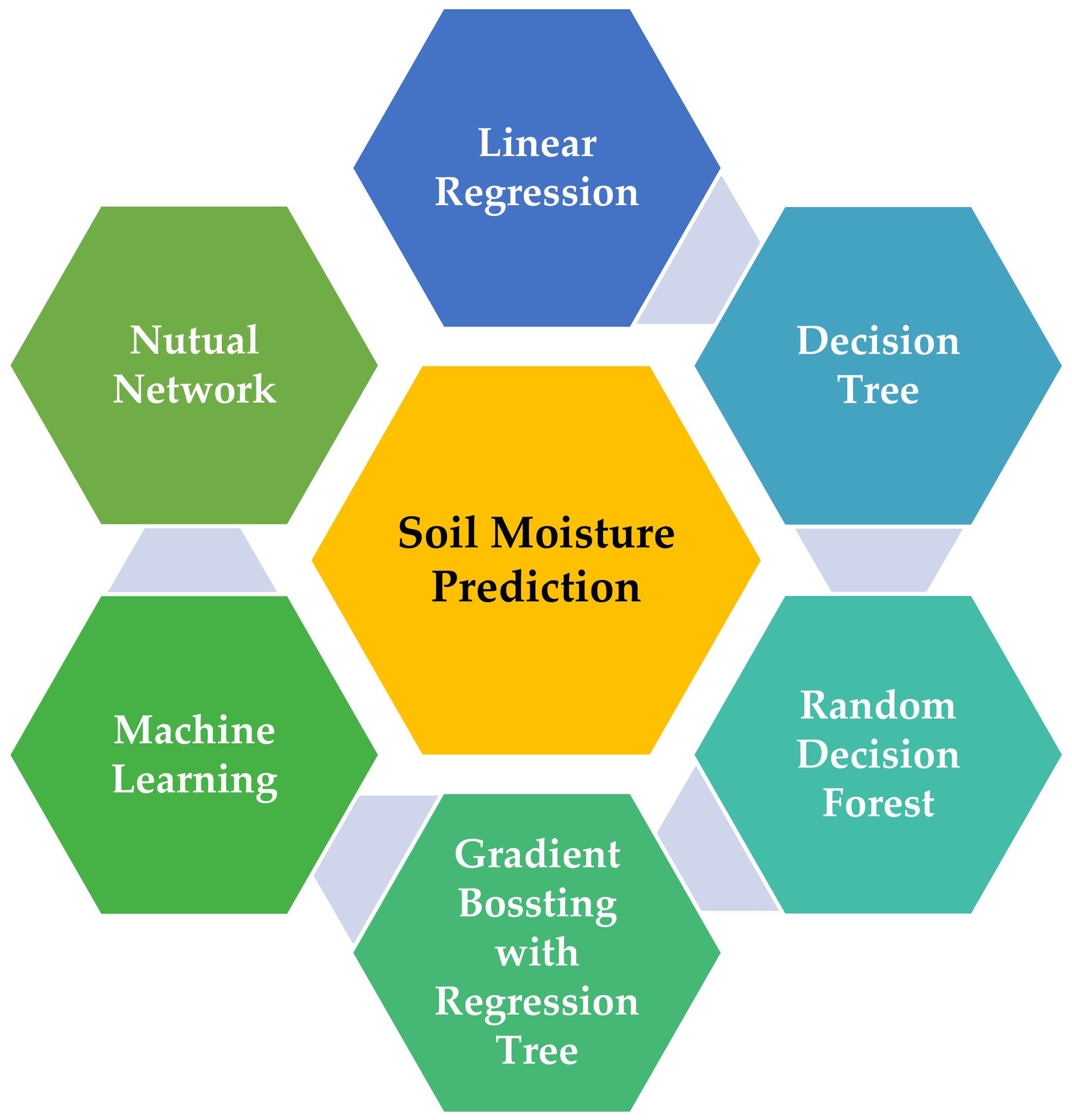
30], a decision tree approach was used to decide the seasonal irrigation frequency and water requirements for the farm based on forecasted soil moisture. Like this, there exist numerous prediction methods for soil moisture, see
Figure 1.
A fuzzy inference that uses IF-THEN (knows as Crisp rules) was also applied to equivalate the soil moisture compared with threshold values collected by sensors to decide whether to switch on an irrigation sprinkler system [
31,
32]. Like this, there are numerous approaches for controlling the sprinkler system see
Table 1.
Table 1.
Summary of the Literature with different control method in Smart Irrigation.
Table 1.
Summary of the Literature with different control method in Smart Irrigation.
| The Method Used to Control the Sprinklers of an Irrigation System | Reference |
|---|
| Supervisory Control and Data Acquisition (SCDA) system-uses the soil sensor to control and monitor the irrigation. The advantage of such an algorithm is it automatically carries out the data collection, preparation, and execution of the water balance management. | [33] |
| Wireless sensor nodes gather fully web-based system (online)—visualization of weather data and soil moisture, and spraying is done where is necessary. The system can send and receive messages and activates the irrigation system automatically. | [34] |
| Internet of Things (IoT) devices–farmers, can receive the data such as soil moisture, humidity, and whether forcing from different IoT sensors and manually or automatically spraying value is opened. | [35] |
Studies also revealed that automation and path navigation are also the other two essential features for designing mobile robotic systems. In ref. [
36], a farm machinery control system was developed to operate multiple tractors on a single large-scale farm by a remote Wireless Local Area Network (WLAN) monitoring system that automates navigation path control simultaneously. The control architecture for path tracking tasks for a mobile robot is usually based on rolling without slipping. However, this is not realistic for an off-road vehicle, such as a tractor or any other agricultural vehicle, as the study in [
37] points out since farming vehicles face problems with sliding wheels and actuator delays. On the same note, this was also demonstrated many strategies that focus on predictive observer-based and adaptive control that can automatically direct farm machinery without an external sensor while dramatically reducing the precision loss for route monitoring.
From the above literature survey, it is clear that smart irrigation provides reliable operations for agricultural activities and efficiently delivers water. At the same time, systems related to pesticide spraying also offer greater efficiency. However, the studies on machinery that offer both functions (water sprinkling and pesticide spraying) are limited as per our knowledge. Hence, this study aims to build a multi-purpose smart farming robot (MpSFR) based on vehicular technology in irrigating the farm. The MpSFR functions with farm monitoring, preprocessing the data for decisions, control, and other irrigation management activities enhanced by soil moisture and plant health prediction. Besides, an experimental investigation is carried out in the test farm to verify the functions of the proposed MpSFR.
The novel contributions of this study are as follows:
Photovoltaic powered battery-operated vehicular technology-based systems for smart irrigation;
Sensor-based autonomous control is used to avoid collisions and obstacles during water sprinkling and pest spraying;
Soil moisture-driven decisions for sprinkling water in the farm area and image-processing for pest detection to decide pest spraying.
The paper is organized as follows. In
Section 2, the multi-purpose smart farming robot’s system design is presented.
Section 3 provides results and discussion based on the test farm investigation.
Section 4 provides the challenges, future research suggestions, and conclusions.
2. Proposed Multi-Purpose Robot for Smart Farming
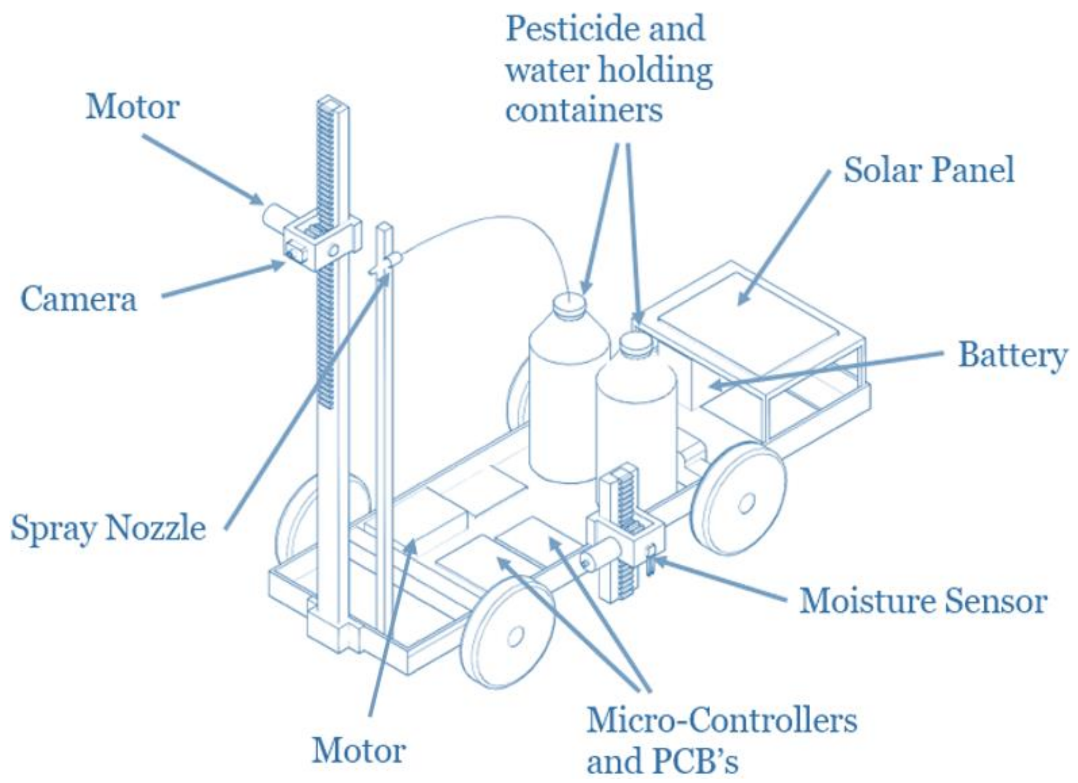
The proposed smart farming robot is inspired based on the vehicular design concepts, and with this, watering and pesticide spraying can be done remotely. The design consists of different components briefly discussed in
Section 2.1. The layout of the proposed MpSFR is shown in
Figure 2.
2.1. Major Components
2.1.1. Soil Moisture Detection
Soil moisture is an integral part of the irrigation system, so data collection requires a sensor inserted near the plant. An on-board HL-69 soil hygrometer moisture sensor manufactured in China is integrated with the MpSFR, and this allows us to measure the soil moisture up to a depth of 0.2 m. The measured Soil Moisture Differences (SMD) are then used to predict whether irrigation is needed or not. The few prominent features of the HL-69 Soil Hygrometer are mentioned in
Table 2.
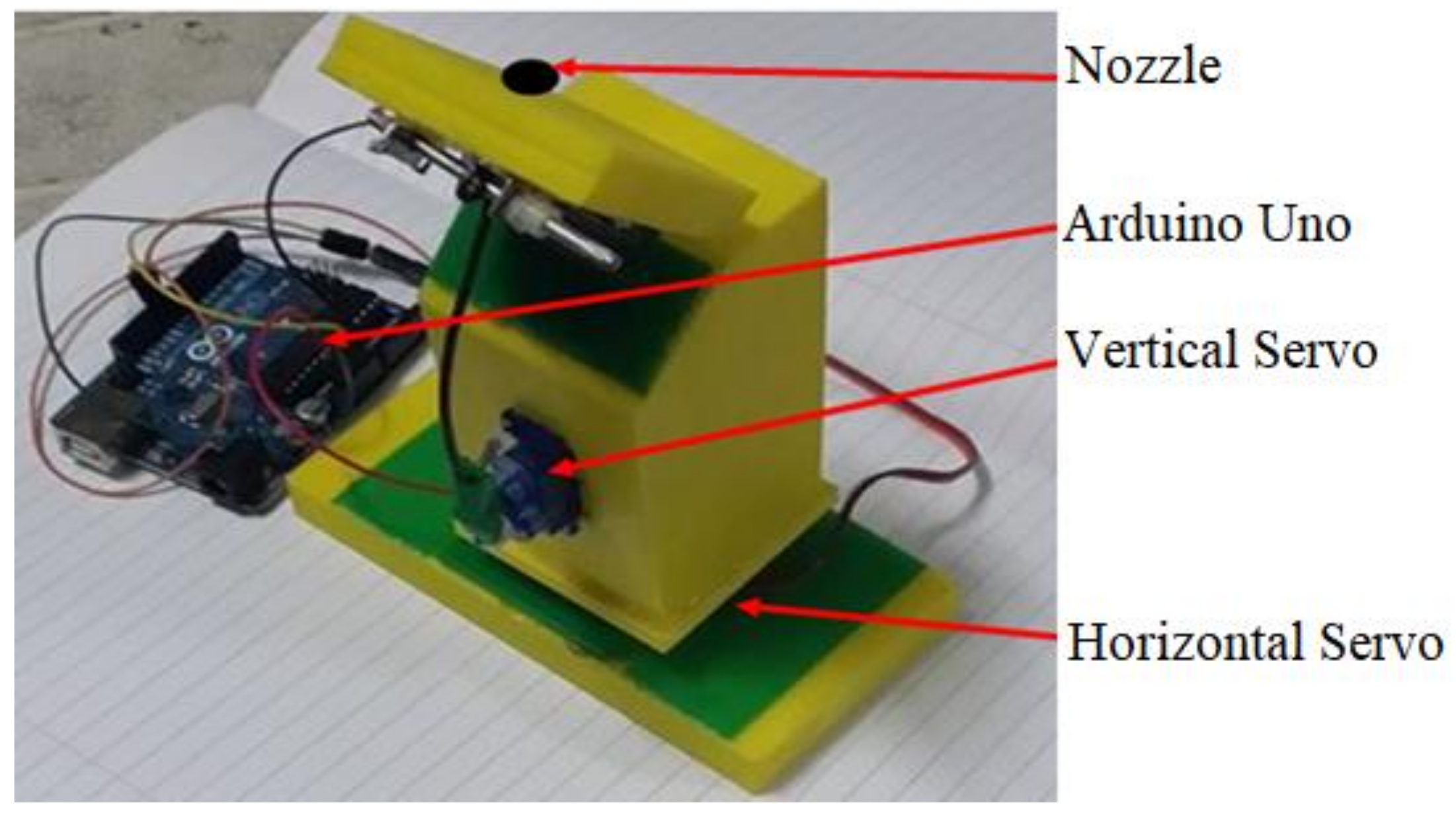
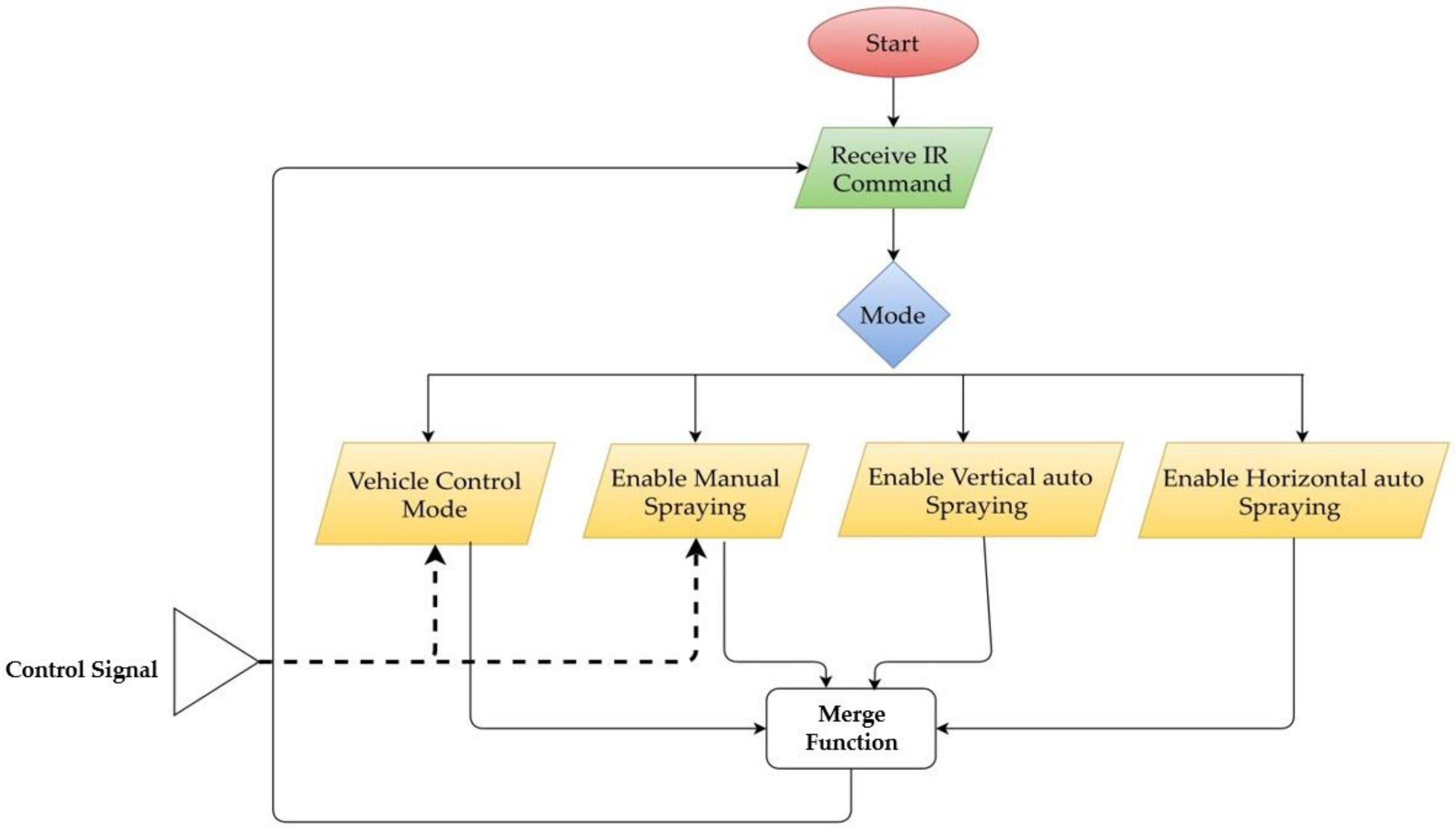
2.1.2. Spraying Mechanism
A spraying mechanism is being designed and developed using two servo motors. It can operate both in a vertical and horizontal motion. At the tip of the spraying nozzle, this spraying system is still kept intact. For this, we selected a full-cone even distribution spray type nozzle, and it can be easily mounted on a spray planter. The pounds per square inch (PSI) range is 20 to 60. The servo mechanism allowed the sprayer to have 180° horizontal freedom and 90° vertical freedom. Arduino Uno R3 microcontroller is used to control the two servo motors. The system is fabricated in a 3D printer using the polylactic acid (PLA) material can be seen in
Figure 3.
In the system, we have three spraying modes, and accordingly, the servo motors have been initialized to operate. An infrared (IR) remote control is provided for the input control. The sprayer used can cover 156 m
2 with a given mode of operation, as in
Table 3.
2.1.3. Mobile Control and Power Circuit Design
As mentioned earlier, the proposed MpSFR is based on vehicular design, and the chassis selection is crucial. For this, we used off-the-shelf “Toyabi” mobile chassis from China. The design consists of a pair of motors to control direction and motions. The user’s movement input with the aid of remote control and movement is taken by manual mode. It is designed to test for an auto mode movement in the test farm, which follows a predefined pattern and is discussed further in
Section 3.
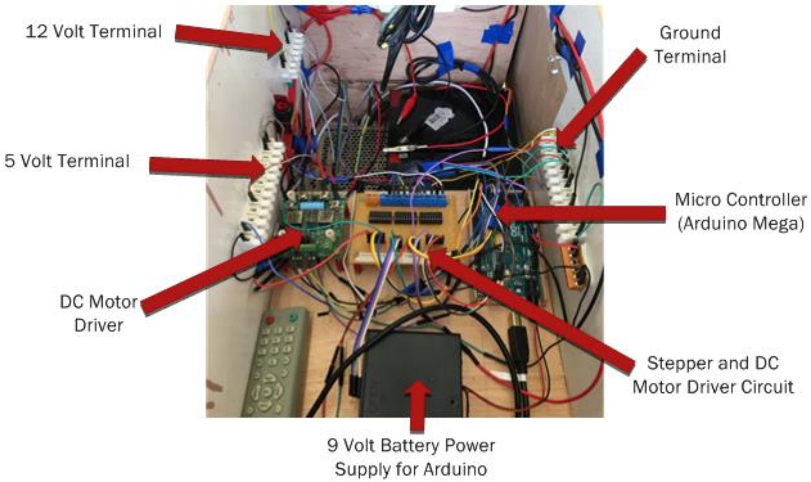
A consistent power supply is essential for any system, especially for battery-operated systems. A power circuit is designed using the H-bridge circuit and shown in
Figure 4. Note that this may not provide the mechanism with adequate current whenever a full load requires from the motors. The direct power switch using bipolar junction transistor (BJT) is operated eventually to supply sufficient current. The power parameters and operating details are given in
Table 4.
To operate the MpSER, the power transistors require a direct current (DC), which is about 200 mA DC at their base. This could not be possible with the microcontroller as it triggers and allows 20 mA output of DC at each output pin. Therefore, a BJT was placed between the pin of the microcontroller and the power transistor to draw current from the 5 V voltage common collector (VCC) supply of the microcontroller, which permitted the source to be up to 200 mA. When the pin is not high in the microcontroller, a 1 k Ohm resistor is placed to control the base’s power transistor.
To make it easier for the user to access the receiver, the IR sensor is conveniently located at the rear side of the MpSFR. The two common heavy objects in the proposed design are the spraying tank and the battery, which are mounted in the center of the vehicle to increase stability by having the center of gravity in the center of the vehicle.
The servo motor which drives the vehicles has been mounted at the height at the very front so that water jets can cover vast distances of about 5 m. Under the top panel, the microcontroller and control circuitry are shielded to prevent any water spillage.
Another reason was that the top panel has a coating of water protecting material that avoided any spillage onto the electrical and electronics components. For MpSFR, the wheel diameter is around 20 cm and is wide enough to navigate over rugged terrain. The process flow of the system is given in
Figure 5.
2.1.4. Working of Water Pump
As the MpSFR is designed with the dual feature: (a) Water sprinkling for irrigation and (b) pesticide spraying. The MpSFR contains a water storage tank driven by a pump connected to the control board and battery. The pump is operated through a driver circuit and signals from the microcontroller. In this operation, the pump receives the command from the remote control.
Here, we used a 12 V DC motor pump and is sufficient to drive the spraying mechanism. The selected motor up can also lift the water to a maximum height of 5 m with a flow rate of 600 L/h. The MpSFR is designed to carry an on-board storage tank of 2.5 L capacity, and this is sufficient to cover at least 50 m2 farm area.
2.1.5. User Interface through IR Remote Controller
The user interface application is developed, taking the compatibility measures suitable for a smartphone. An 1838T IR sensor can provide inputs to the controller on the board. For MpSFR operation, nozzle placement, pump control, and spraying mode option, a series of commands are given.
The Samsung WatchON program has been used for the propagation of IR signals as a remote control. The user interface consists of an option to drive the vehicle forward and backward. As well, pause and enter options for farming functions. The directional buttons are used to mount the servo motor system manually, and the middle button is used to turn the pump on the spray. To enter the mode that the user needs, the numbers on the bottom right are used.
2.1.6. Image Processing
Image processing is an essential feature that is used in pest detection in smart farming applications. With an MpSFR based irrigation system controlling and protecting the plants from various types of insects is the added advantage. Therefore, an IR FLIR A65 Thermal Camera is used, mounted in the designed vehicle as it is a light-weight design, so there was no major issue in implementing it. The FLIR A65 camera gives a good quality image of 320 × 256 pixels. An added benefit is that it can also produce a thermal image of 640 × 512 pixels.
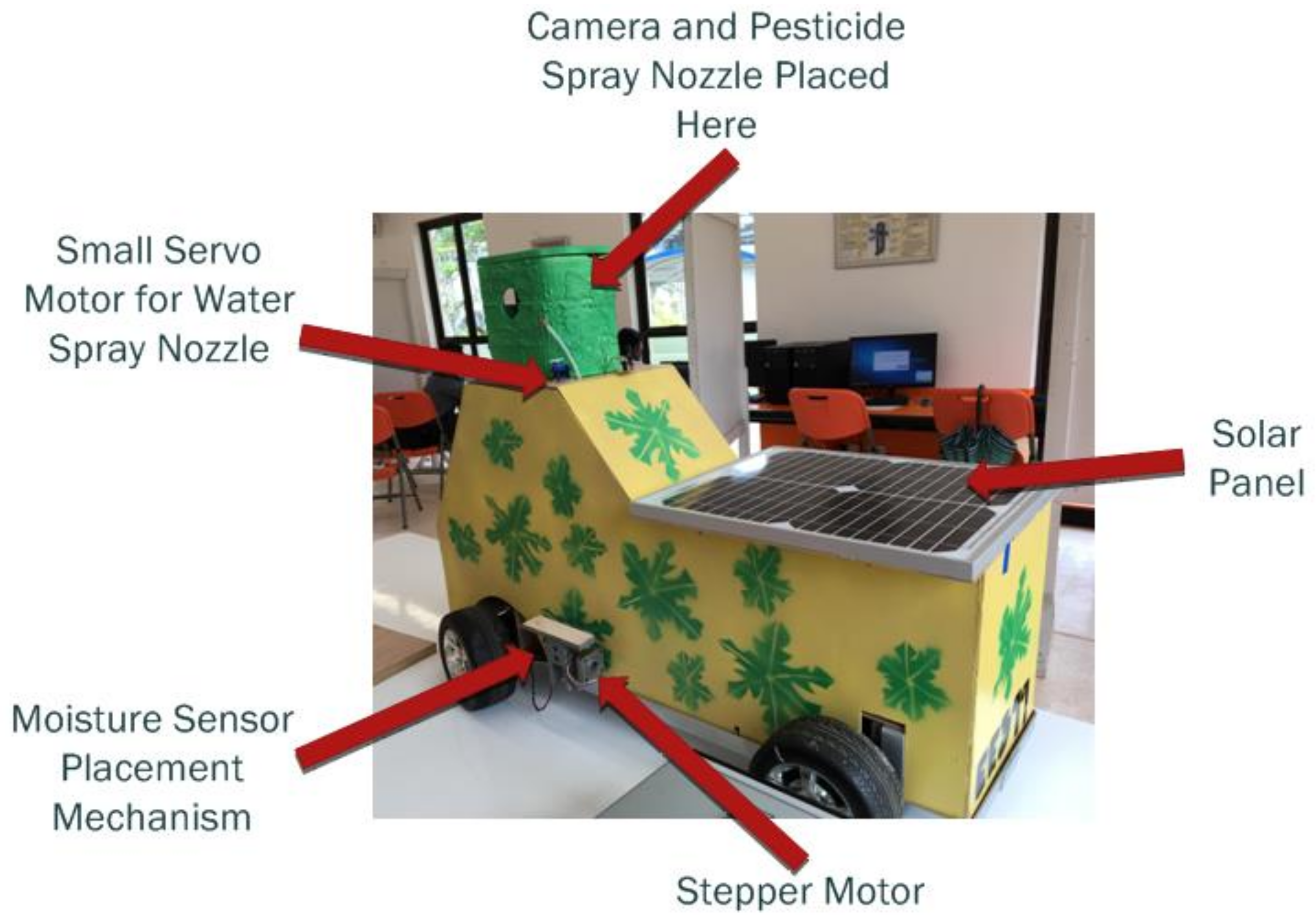
2.2. Design of the Multi-Purpose Smart Farming Robot
Based on the schematic representation and the components discussed in
Section 2.1. the MpSFR system is designed. Initially, a conceptual model was developed for testing purposes, and later it was developed with the correct sizes considering the weights and functions of the onboard components. In the conceptual model, the solar photovoltaic module is not used, but the final design of the MpSFR has an on-board solar photovoltaic array connected to the battery through a power converter, which helps in charging the battery and reduces dependency on grid power.
Figure 6 shows the final prototype of the designed MpSFR. The designed MpSFR has some safety features such as obstacle detection and safe operation following the farm line path. Not only the safe operation in the MpSFR movement but also the controlled operation of sensor and camera. Here, the motors implant the soil moisture sensor into the ground and move the camera up and down to understand the soil moisture and pests better.
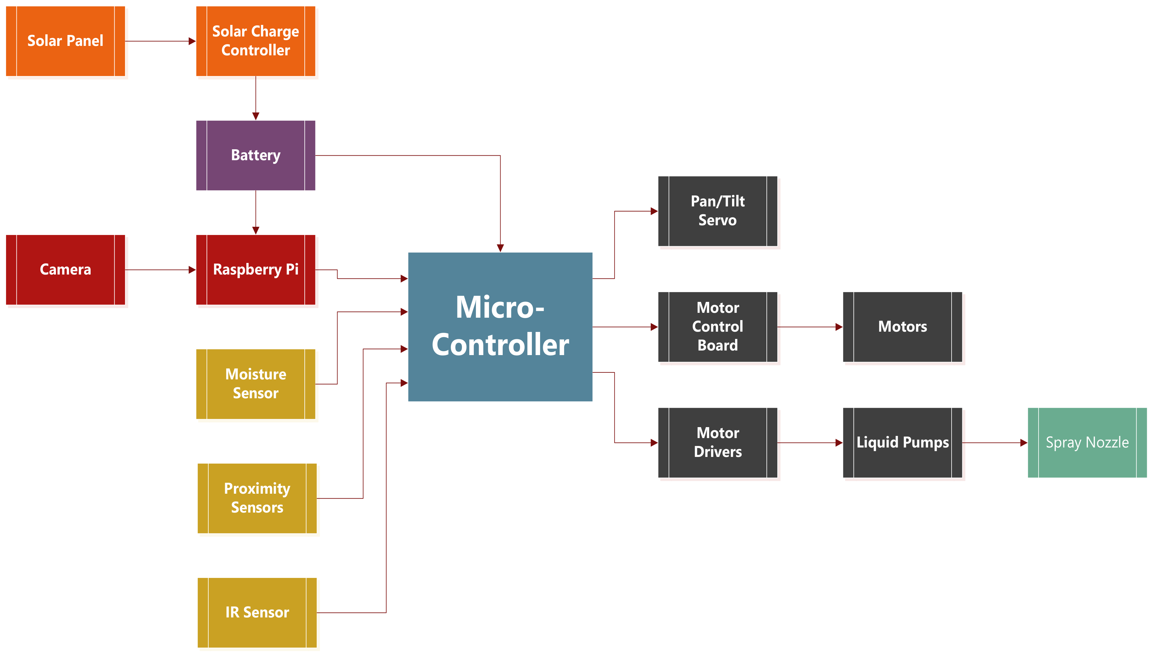
2.3. Methodology
This section provides the methodology that we used for verifying the operations of the designed MpSFR. In
Figure 7, the methodological operational flow and system components integration is shown. We use the microcontroller during the operation backflow and at this point the electromotive force (EMF) need to be monitored. So, three diodes were inserted along with the motor’s terminals in the control circuit configuration, which stops the back EMF from flowing. The BJT transistors in between also provided a type of separation between the low and high-power circuits.
From
Figure 7, it can be seen that the power circuit, sensing elements, motoring operations, and function delivery controls are mainly based on the microcontroller decisions. In
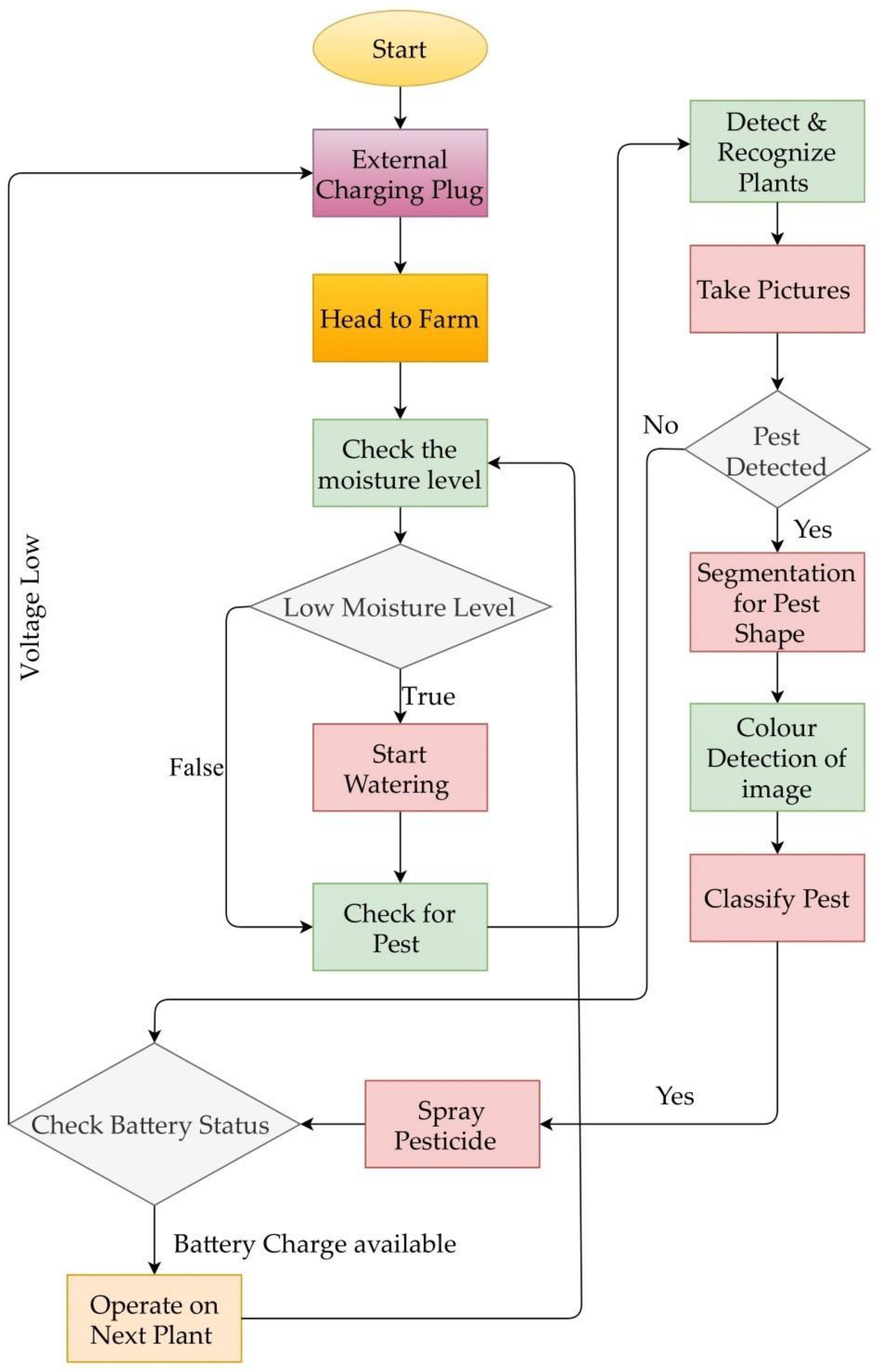
Figure 8, we have presented the detailed methodology about the water sprinkling and pesticide spraying decisions initiated by the MpSFR based on its intelligent sensing capabilities.
Step by step operation is given below:
Step-1: The MpSFR starts heading towards the farm area, and at this step, it is made sure that the batteries are fully charged, also the storage tanks with water and required pesticides;
Step-2: Once the MpSFR reaches the first plant, the probes of the sensor placed in a water-sealed PCB package will be sticking out to measure the soil moisture at a depth of 0.2 m from the surface;
Step-3: The measured soil moisture data is compared with the standard values, and here if the observed soil moistures are lesser, then the watering decision is made where the pump motor starts operating to deliver the water to the plant through the sprinkler nozzle;
Step-4: Once the plant’s watering is done or higher soil moistures are measured, the MpSFR starts operating its camera to check for the pests possible by applying image processing for the captured plant image. The pest detection, segmentation for the pest shape, and pest classification features allow the MpSFR to choose the required pesticide, and accordingly, the MpSFR sprays the pesticide;
Step-5: If no pest is identified, then the MpSFR will check for its available energy in the battery and the weather conditions (for example, favorable for solar charging or not). Here, if it is found that the battery energy level is lower and the solar charging conditions are not favorable, the MpSFR takes the help of an external charging plug;
Step-6: If the battery energy is available, then the MpSFR moves to the next plant. As well, in the favorable solar energy condition, the MpSFR continuous to move forward by checking the plants one by one.
3. Results and Discussion
The designed MpSFR is experimentally verified by operating it in the test farm in the Papaya farm in Fiji, a Pacific Island nation. The main reason for selecting this location is that water availability in the dry season for Papaya production is one of the significant issues. As well, it is regarded as the agro-ecological constraints faced by the farmers around the Pacific Islands. However, many techniques and tools are developed and proposed to plan irrigation in the Pacific Islands. Still, due to various other reasons, their implementation has not seen a full potential. Here are some of the drawbacks and challenges: conditions of limited water resources in the wells, boreholes, etc., variability of rainfall, water stress indicators, irrigation efficiency, costs, incentives, and knowledge transfer issues. We believe the proposed concept of MpSFR could solve a few of the challenges and allow the farmers in Pacific Islands to schedule irrigation remotely. As mentioned earlier, in the Papaya farm, a scale-down test field (10 m × 8 m) whose area is approximately 80 m
2 is selected. The selected test field of the Papaya farm has 99 plants where each plant is separated by 1 m apart. In
Figure 9, the pattern of mobile irrigation as per the considered Papaya test field is shown, which allowed us to run the experiment smoothly. The designed MpSFR followed the test field pattern considering the methodological process discussed in
Section 2.3. The results of this experimental investigation were analyzed and discussed below.
As shown in
Figure 9; 11 × 2 = 22, radio-frequency identification (RFID) tags are placed on the test field along the two far end horizontal rows of the Papaya plant’s location and marked as (T
S1–T
S11) & (T
E1–T
E11) for the irrigation starting/ending point for each column of the plants. Due to the no-contact and non-line-of-sight nature of this technology, RFID is very promising and economical. An MpSFR fitted with a single working RFID reader [
8] can easily detect an RF tag. RFID automatically recognizes and monitors an entity using radio waves and consists of two main elements: a data-carrying unit (tag/transponder) and a reader (transceiver).
Usually, the RFID tag holds a serial number on an electronic microchip that recognizes an attached entity and attaches this microchip to an antenna that allows it to relay the identifying information to the reader that decodes the signals and transmits the information to a middleware (computer, robot control system, etc.). Middleware may be connected to other systems or networks that need more analytical information.
The MpSFR is placed close to the test field using a manual mode of operation near the RFID tag T
S1, as shown in
Figure 9. Once the automatic irrigation mode is active, then the RFID reader will scan for the tag T
S1 if the scan confirms the availability of the tag T
S1, which confirms the starting point of the irrigation. After that, the controller scans the soil parameters (i.e., moisture and temperature) for node N
1 (see
Figure 10 for the MpSFR measured soil moisture in the test farm). Obtained values are crossed-checked with the required crop parameters from the predefined database and check the weather forecast for the day. If the MpSFR decision is to water the plants for that particular zone (surrounding area; approximately 2 × 2 = 4 m
2), then the spray nozzle is oriented toward the plants and starts irrigation, keeping the flow distance at 2 m. Once the watering is finished for that particular zone (a shaded quarter circular areas as per
Figure 9), the MpSFR starts following the imaginary line further (approximately 0.5 m keeping a distance from the 1st column of the plants, shown in
Figure 9 as a dotted line on the left). Then the MpSFR reaches close to the N
2. Following the same procedure (having the information from N
2), MpSFR irrigates the next zone (i.e., 4 × 2 = 8 m
2; with a half-circular shaded area); if required, else skip the zone and reaches close to the N
3 and repeats the process. By this time, the MpSFR already arrived at the last row (end position for that particular column), confirmed by the scan data from tag T
E1. Then the MpSFR turns left and crosses a distance of 2 m; again, turn left to follow the next imaginary line. Tags T
E2 and T
E3 confirm the right path for the MpSFR. Based on the data provided by node N
4 the MpSFR either starts or skips irrigation for that particular zone and reached the end position for that respective column followed by the next column repeating the same procedure until it reaches the finish position, which confirms by the RFID tag. During this operation, the MpSFR uses an ultrasonic sensor to avoid collisions and obstacles and abort the mission once any obstacle is detected, followed by an alert message to the farm owner.
The water sprinkling distance range and the area are presented in
Figure 11a,b. The range (Dx = 10.2 m) is the maximum horizontal distance reached by the MpSFR, given in
Figure 11a. We used Equation (1) to estimate the MpSFR’s water sprinkling distance. We obtained a maximum vertical angle of 45° with an initial velocity
Vi of:
The maximum area that MpSFR covers is given in
Figure 11b. The field is accessible by a sprinkler with a horizontal reach of 180°, a vertical height of ±45°, a minimum horizontal reach of 0.5 m, and a maximum reach of 10 m. From
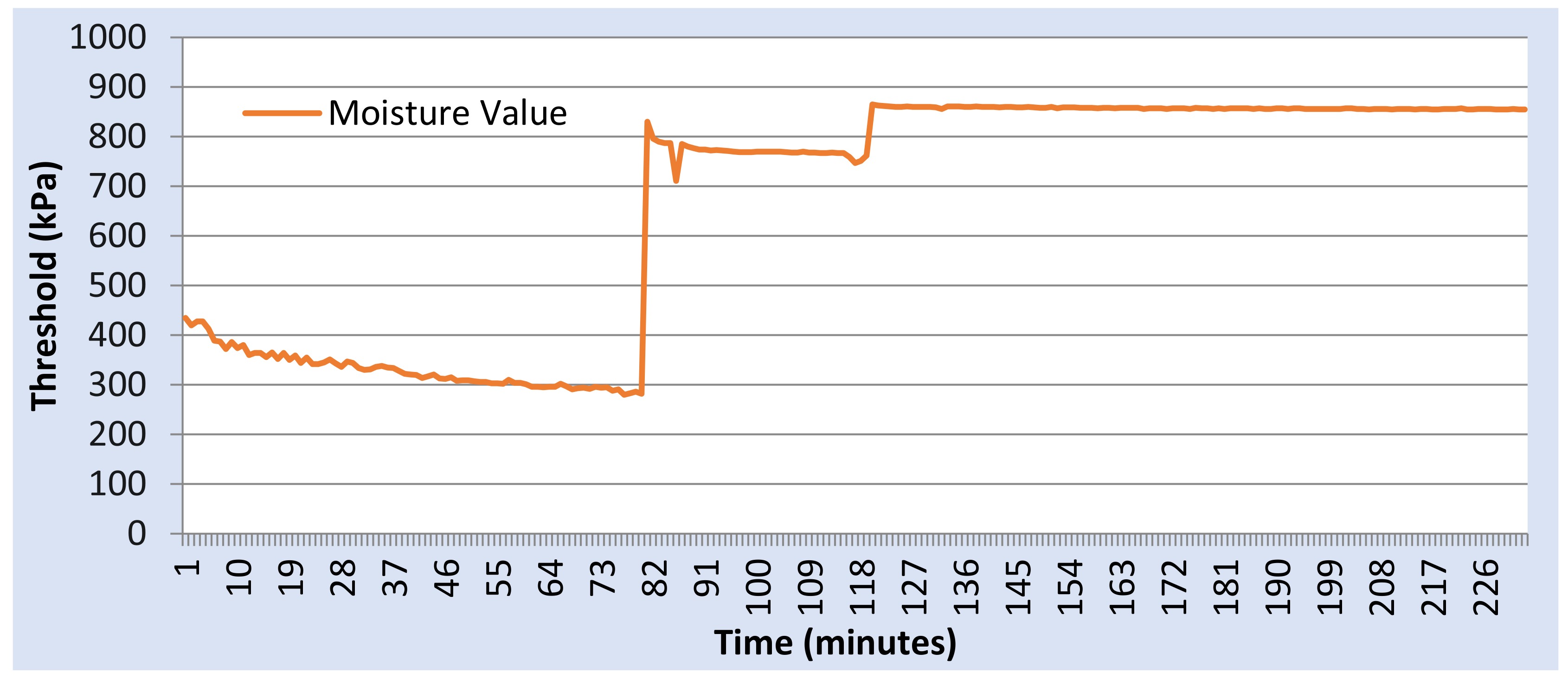
Figure 10 and
Figure 11, it was observed that the proposed MpSFR has a favorable sprinkling range as well as the area covered. Based on the field testing, the soil moisture measurement results shown in
Figure 10 reveal that the sensor trigger after 81 min requires water, and once the MpSFR does the watering, the soil gets wet, and irrigation stops after 800 thresholds.
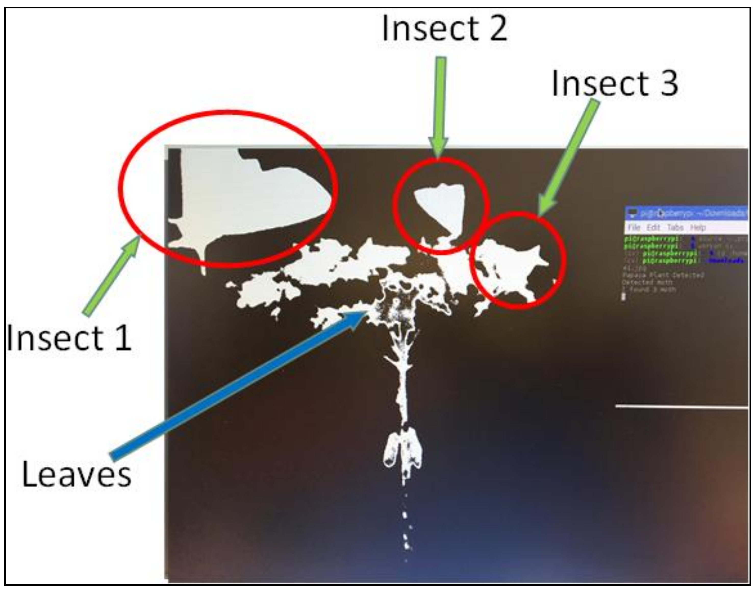
Apart from the watering, the pesticide spraying results are also presented. As mentioned earlier, the MpSER was designed with a dual feature. Detecting insects by applying image processing is the smart feature that enabled this MpSFR suitable for modern farming. The pest detection experiments were conducted twice a month using the designed MpSFR, mainly due to Fiji’s climate conditions. The analysis that is obtained from the image processing technique is shown in
Figure 12.
Based on the observations from
Figure 12, the leaf and the detected insects are labeled.
Figure 13 provided the information on detecting 1 insect, which is done to have a detailed understanding of how the insect is detected in the field testing of the MpSFR.
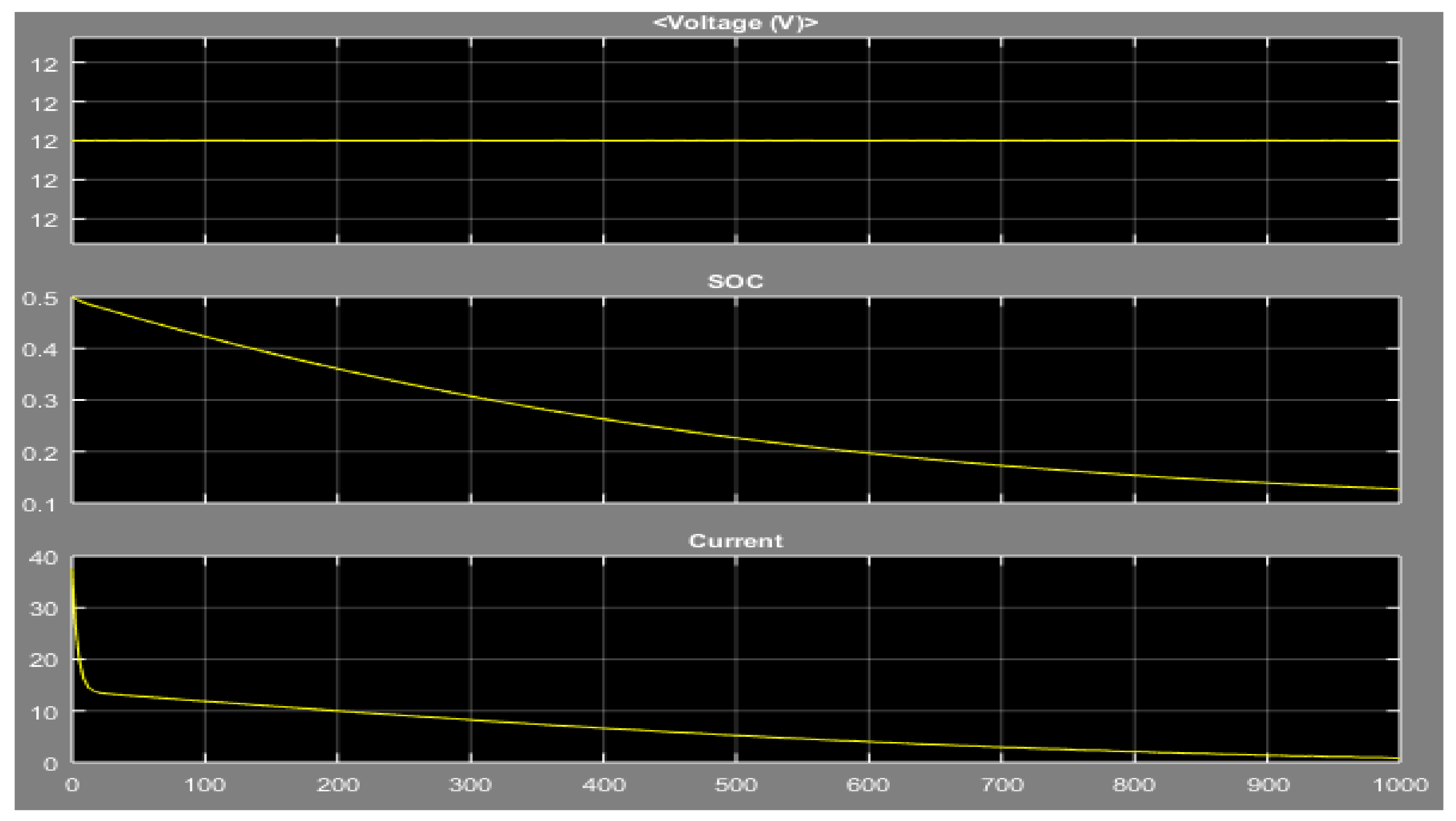
From the experimental investigation in the Papaya field, it is understood that the MpSFR operates effectively by sprinkling water and spraying pesticide wherever it is needed. As well, as mentioned earlier, the MpSFR starts it working with a fully charged battery. The test run process in the Papaya fields was conducted, and the MpSFR was entirely operated on battery mode where solar panels charge the battery. Hence, this suggests looking into the battery characteristics, as shown in
Figure 14.
The analyzed results show that the proposed MpSFR based on IoT and computer vision technologies can be considered a smart farming tool. The controller mounted on the MpSFR helps change the irrigation schedule based on the plant’s watering needs rather than on a defined, predetermined schedule. The MpSFR controller automatically decreases the watering time, usually during the cooler months (these months generally need less water). On the other side, when outdoor temperatures rise or precipitation declines, the SMIS controller of the MpSFR varies the operating times or irrigation systems schedule to compensate for the fluctuation. With all the features mentioned earlier, the MpSFR automatically alters the irrigation schedules depending on site-specific factors, such as adjustments in soil type and local conditions, and irrigates/skips the corresponding plant according to the received signal.
4. Conclusions and Future Scope
A prototype of the automatic water sprinkling and pesticide spraying autonomous vehicle called multi-purpose smart farming robot (MpSFR) was designed and tested successfully for agricultural application. A robust power circuit is provided, which supplies voltages to all the components of the MpSFR without any interference, and this mainly due to the photovoltaic powered onboard battery system. The experimental investigation suggested that the MpSFR was able to sense the soil moisture and detect the pests from the Papaya test field. Based on the sensing and detection capabilities, the decisions on irrigation and pest spraying were made effectively. Overall, it is understood that the proposed MpSFR is smart, self-protective, and reliable in performing farming activities. Thus, developing farming robots like the MpSFR presented in this study would enable farmers to plan irrigation by reducing water and energy costs.
However, there exist a few research challenges that need further investigation. In the current stage, in Pacific Islands, farming is at an early stage to apply to automated decision-making and predictive solutions. The situation is similar in many developing nations. Hence there is a massive possibility for other digital technologies like information management systems and blockchain. We also expect that these digital technologies’ applications need to be more robust when it comes to real-time operation. On the other side, the involvement of AI, IoT, Blockchain, etc., might not be cost-effective. Hence, understanding the techno-economic feasibility would be an important research area. Another research direction is on the system operation that should user-friendly; as well, as these systems operate in a remote environment, their operation and maintenance should be affordable.


 ,
, 


